EP2105083B1 - Endoskop - Google Patents
Endoskop Download PDFInfo
- Publication number
- EP2105083B1 EP2105083B1 EP09165193.5A EP09165193A EP2105083B1 EP 2105083 B1 EP2105083 B1 EP 2105083B1 EP 09165193 A EP09165193 A EP 09165193A EP 2105083 B1 EP2105083 B1 EP 2105083B1
- Authority
- EP
- European Patent Office
- Prior art keywords
- lens
- image
- ocular
- relay
- lenses
- Prior art date
- Legal status (The legal status is an assumption and is not a legal conclusion. Google has not performed a legal analysis and makes no representation as to the accuracy of the status listed.)
- Expired - Lifetime
Links
- 230000003287 optical effect Effects 0.000 claims description 76
- 238000000034 method Methods 0.000 claims description 30
- 230000004075 alteration Effects 0.000 claims description 22
- 238000003384 imaging method Methods 0.000 claims description 12
- 230000033001 locomotion Effects 0.000 claims description 6
- 238000005452 bending Methods 0.000 claims 1
- 239000011521 glass Substances 0.000 description 13
- 230000001965 increasing effect Effects 0.000 description 7
- 238000001356 surgical procedure Methods 0.000 description 7
- 238000012546 transfer Methods 0.000 description 5
- 230000005540 biological transmission Effects 0.000 description 4
- 238000013461 design Methods 0.000 description 4
- 230000005284 excitation Effects 0.000 description 4
- 230000000712 assembly Effects 0.000 description 3
- 238000000429 assembly Methods 0.000 description 3
- 150000001875 compounds Chemical class 0.000 description 3
- 239000000428 dust Substances 0.000 description 3
- 230000000694 effects Effects 0.000 description 3
- 210000001015 abdomen Anatomy 0.000 description 2
- 230000008901 benefit Effects 0.000 description 2
- 230000008859 change Effects 0.000 description 2
- 238000001839 endoscopy Methods 0.000 description 2
- 238000002357 laparoscopic surgery Methods 0.000 description 2
- 238000002324 minimally invasive surgery Methods 0.000 description 2
- 238000011084 recovery Methods 0.000 description 2
- 230000035945 sensitivity Effects 0.000 description 2
- 210000000683 abdominal cavity Anatomy 0.000 description 1
- 230000006978 adaptation Effects 0.000 description 1
- 208000003464 asthenopia Diseases 0.000 description 1
- 238000001444 catalytic combustion detection Methods 0.000 description 1
- 238000002574 cystoscopy Methods 0.000 description 1
- 230000003247 decreasing effect Effects 0.000 description 1
- 230000000593 degrading effect Effects 0.000 description 1
- 230000002939 deleterious effect Effects 0.000 description 1
- 230000001419 dependent effect Effects 0.000 description 1
- 238000001514 detection method Methods 0.000 description 1
- 238000003745 diagnosis Methods 0.000 description 1
- 238000002405 diagnostic procedure Methods 0.000 description 1
- 230000003292 diminished effect Effects 0.000 description 1
- 239000012636 effector Substances 0.000 description 1
- 238000011846 endoscopic investigation Methods 0.000 description 1
- 230000002708 enhancing effect Effects 0.000 description 1
- 238000003780 insertion Methods 0.000 description 1
- 230000037431 insertion Effects 0.000 description 1
- 238000007689 inspection Methods 0.000 description 1
- 230000003993 interaction Effects 0.000 description 1
- 230000001678 irradiating effect Effects 0.000 description 1
- 238000004519 manufacturing process Methods 0.000 description 1
- 239000000463 material Substances 0.000 description 1
- 238000005259 measurement Methods 0.000 description 1
- 230000007246 mechanism Effects 0.000 description 1
- 238000012978 minimally invasive surgical procedure Methods 0.000 description 1
- 238000012986 modification Methods 0.000 description 1
- 230000004048 modification Effects 0.000 description 1
- 239000005304 optical glass Substances 0.000 description 1
- 238000012634 optical imaging Methods 0.000 description 1
- 239000002245 particle Substances 0.000 description 1
- 238000012545 processing Methods 0.000 description 1
- 238000000926 separation method Methods 0.000 description 1
- 210000001835 viscera Anatomy 0.000 description 1
Images


Classifications
-
- A—HUMAN NECESSITIES
- A61—MEDICAL OR VETERINARY SCIENCE; HYGIENE
- A61B—DIAGNOSIS; SURGERY; IDENTIFICATION
- A61B1/00—Instruments for performing medical examinations of the interior of cavities or tubes of the body by visual or photographical inspection, e.g. endoscopes; Illuminating arrangements therefor
- A61B1/04—Instruments for performing medical examinations of the interior of cavities or tubes of the body by visual or photographical inspection, e.g. endoscopes; Illuminating arrangements therefor combined with photographic or television appliances
- A61B1/055—Instruments for performing medical examinations of the interior of cavities or tubes of the body by visual or photographical inspection, e.g. endoscopes; Illuminating arrangements therefor combined with photographic or television appliances having rod-lens arrangements
-
- G—PHYSICS
- G02—OPTICS
- G02B—OPTICAL ELEMENTS, SYSTEMS OR APPARATUS
- G02B23/00—Telescopes, e.g. binoculars; Periscopes; Instruments for viewing the inside of hollow bodies; Viewfinders; Optical aiming or sighting devices
- G02B23/24—Instruments or systems for viewing the inside of hollow bodies, e.g. fibrescopes
- G02B23/2407—Optical details
- G02B23/2446—Optical details of the image relay
-
- G—PHYSICS
- G02—OPTICS
- G02B—OPTICAL ELEMENTS, SYSTEMS OR APPARATUS
- G02B25/00—Eyepieces; Magnifying glasses
- G02B25/001—Eyepieces
-
- A—HUMAN NECESSITIES
- A61—MEDICAL OR VETERINARY SCIENCE; HYGIENE
- A61B—DIAGNOSIS; SURGERY; IDENTIFICATION
- A61B1/00—Instruments for performing medical examinations of the interior of cavities or tubes of the body by visual or photographical inspection, e.g. endoscopes; Illuminating arrangements therefor
- A61B1/00163—Optical arrangements
- A61B1/00188—Optical arrangements with focusing or zooming features
-
- A—HUMAN NECESSITIES
- A61—MEDICAL OR VETERINARY SCIENCE; HYGIENE
- A61B—DIAGNOSIS; SURGERY; IDENTIFICATION
- A61B1/00—Instruments for performing medical examinations of the interior of cavities or tubes of the body by visual or photographical inspection, e.g. endoscopes; Illuminating arrangements therefor
- A61B1/00163—Optical arrangements
- A61B1/00193—Optical arrangements adapted for stereoscopic vision
-
- A—HUMAN NECESSITIES
- A61—MEDICAL OR VETERINARY SCIENCE; HYGIENE
- A61B—DIAGNOSIS; SURGERY; IDENTIFICATION
- A61B1/00—Instruments for performing medical examinations of the interior of cavities or tubes of the body by visual or photographical inspection, e.g. endoscopes; Illuminating arrangements therefor
- A61B1/04—Instruments for performing medical examinations of the interior of cavities or tubes of the body by visual or photographical inspection, e.g. endoscopes; Illuminating arrangements therefor combined with photographic or television appliances
- A61B1/042—Instruments for performing medical examinations of the interior of cavities or tubes of the body by visual or photographical inspection, e.g. endoscopes; Illuminating arrangements therefor combined with photographic or television appliances characterised by a proximal camera, e.g. a CCD camera
Definitions
- the present invention is generally related to optical devices and methods such as those used for surgery.
- the present invention relates to techniques for enhancing the throughput and manipulation of optical information through a limited cross-section endoscopic relay.
- the invention provides an endoscope having an optical relay, objective, or ocular using at least one intermediate image formed within an optical component such as a glass element or lens.
- the invention provides an ocular system that permits independent adjustment of the diopters, magnification, X-Y positioning and rotational orientation of an image, while introducing minimal aberrations.
- Minimally invasive medical techniques are aimed at reducing the amount of extraneous tissue which is damaged during diagnostic or surgical procedures, thereby reducing patient recovery time, discomfort, and deleterious side effects.
- the average length of a hospital stay for a standard surgery is significantly longer than the average length for the equivalent surgery performed in a minimally invasive surgical manner.
- Patient recovery times, patient discomfort, surgical side effects, and time away from work are also reduced with minimally invasive surgery.
- the most common form of minimally invasive surgery may be endoscopy.
- endoscopy Probably the most common form of endoscopy is laparoscopy, which is minimally invasive inspection and surgery inside the abdominal cavity.
- laparoscopy In standard laparoscopic surgery, a patient's abdomen is insufflated with gas, and cannula sleeves are passed through small (approximately 1/2 inch) incisions to provide entry ports for laparoscopic surgical instruments.
- the laparoscopic surgical instruments generally include a laparoscope for viewing the surgical field, and working tools defining end effectors.
- the surgeon passes these working tools or instruments through cannula sleeves to a desired internal surgical site and manipulates the tools from outside the abdomen.
- the surgeon often monitors the procedure by means of a television monitor which displays an image of the surgical site via the laparoscopic camera.
- Similar endoscopic techniques are employed in, e.g., arthroscopy, retroperitoneoscopy, pelviscopy, nephroscopy, cystoscopy, cisternoscopy, sinoscopy, hysteroscopy, urethroscopy, and the like.
- Minimally invasive telesurgical systems are now being developed to increase a surgeon's dexterity, so that the surgeon performs the surgical procedures on the patient by manipulating master control devices to control the motion of servomechanically operated instruments.
- the surgeon is again provided with an image of the surgical site via an endoscope.
- the endoscope may optionally provide the surgeon with a stereoscopic image to increase the surgeon's ability to sense three-dimensional information regarding the tissue and procedure.
- Endoscopes typically include three optical sub-systems: an objective lens system, an ocular lens system, and a relay lens system.
- the objective lens system is located at the distal portion of the endoscope to capture the desired image.
- the ocular lens system or eyepiece is located at the proximal portion of the endoscope and generally remains outside the patient body to transmit the desired image to the eye, camera, or the like.
- the relay lens system is generally disposed between the objective and ocular to transfer the image proximally out of the patient along a relatively small diameter endoscope shaft.
- the objective lens system is typically separated from the relay system by an objective-relay air gap, while the relay system is separated from the ocular lens system by a relay-ocular air gap.
- the relay will typically be separated into a series of relay lens units, with the relay units again being separated by gaps.
- the objective lens system generally forms a first intermediate image in the objective-relay gap.
- the relay lens system then transfers this intermediate image from the distal portion of the scope toward the proximal portion by generating as many intermediate relay images as appropriate to travel the length of the shaft. A last intermediate image is produced by the relay system in the relay-ocular gap.
- the ocular collimates or nearly collimates this final intermediate image for detection by a surgeon's eye via viewing lenses such as an eyepiece, or for transmission to the imaging optics of a camera, the camera optics typically forming a final image on a charge couple device (CCD) of the camera.
- CCD charge couple device
- the ocular lens system of known monoscopic endoscopes typically has a plurality of lenses that can manipulate the captured image.
- the optical properties of the captured image can be modified to ensure proper viewing of the desired object within the body. While such adjustments may be adequate for monoscopic endoscopes, when imaging a target site with a stereo imaging optics, it is of particular importance to have very accurate adjustments between the stereo channels to provide accurate three dimensional information that can be matched between the two channels. If accurate matching is not accomplished, the stereo viewer will provide an inaccurate image and may cause eye strain for the user.
- Robotic surgical systems which might make use of the improved imaging capabilities of the present invention are described in the following U.S. Patent Application Numbers: 09/378,173; filed August 20, 1999 ; 09/433,120, filed November 3, 1999 ; and 09/418,726, filed October 15, 1999 .
- WO 94/13189 discloses an endoscope having a first end for insertion into a body with an optical image-forming lens device in the first end for forming two, side-by-side images of an object on opposite sides of the central axis of the endoscope.
- the images are transmitted to the opposite end of the endoscope, where they are received by a viewing device for three-dimensional viewing of the images by an operator.
- An image converging mechanism is provided in the image paths to provide a suitable convergence angle between the images at the viewing device.
- EP 0 066 374 discloses an endoscope comprising an objective system for forming an image of an object and relay lens systems acting as image transmitting means, wherein the objective lens system, or the relay lens system or part of one or both systems is made movable to vary the magnification or adjust the focus.
- the movable part of the lens system(s) is connected to the tip of a movable pipe-shaped member which is movable forward and rearward from the rear end by a driving means having a fine movement adjusting function in an operating part to facilitate magnification variation of focus adjustment in the observing optical system.
- GB 2 068 581 discloses a wide angle objective located at the entrance face of a flexible image guide tube of an endoscope and a variable focal length eyepiece lens system located at the exit face of the tube.
- the variable focal length eyepiece lens system includes at least one axially movable lens group which may increase the magnification of the endoscope from the normal 20 times to about 40 times.
- US 5 749 830 discloses a fluorescent endoscope apparatus having: an endoscope that irradiates a subject portion to be observed with light transmitted through a light transmission device to obtain an object image of the subject portion to be observed; a normal observation light generating device for emitting normal light for performing normal light endoscope observation; a fluorescent observation light generating device for emitting excitation light for performing fluorescent light observation; an introduced-light switching device for selectively introducing, to the light transmission device of the endoscope, normal light emitted by the normal observation light generating device or excitation light emitted by the fluorescent observation light generating device; and an image sensing device for capturing a normal light image of the subject portion to be observed that can be obtained by irradiating the subject portion to be observed with normal light or excitation light or a fluorescent image that can be obtained due to irradiation with excitation light, the image sensing device being included or connected to the endoscope.
- the present invention provides a method of manipulating an image captured by a stereoscopic endoscope imaging device and a stereoscopic endoscope as set out in the appended claims.
- the present invention provides a method of manipulating an image captured by a stereoscopic endoscope imaging device, the method comprising: setting a diopters of the captured image by axially moving a plurality of lenses contained in an ocular system within said stereoscopic imaging device; independently altering magnification of an image, using at least one of said plurality of lenses, without significantly affecting the diopters; adjusting the X-Y positioning of the image, using at least one of said plurality of lenses, wherein at least one of the lenses is moved off an optical axis of the ocular system, without introducing aberrations or affecting the diopters and the magnification; and rotating an orientation of the captured image by the ocular system, wherein the rotating does not affect the diopters, the magnification, and the X-Y positioning of the captured image
- a method of manipulating an image within a stereoscopic imaging device comprising at least a first lens, a second lens, a third lens and the ocular system further comprising a prism, the plurality of lenses and the prism being positioned in an optical path of the ocular system, the independently altering the magnification further comprising maintaining the position of the first lens and moving the second and third lens to adjust the magnification of the image; the adjusting the X-Y positioning of the image further comprising adjusting an orthogonal positioning of the second lens to adjust the X-Y position of the image; and the rotating the orientation of the captured image further comprising rotating the prism to adjust the rotational orientation of the image.
- the invention has applications for any lens systems that transfer optical information through a relay (a series of small diameter lenses) such as, for example, monoscopes, stereoscopes, horoscopes, periscopes, arthroscopes, and the like.
- a relay a series of small diameter lenses
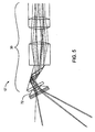
- an endoscope 10 extends through a body wall W to an internal viewing site within a patient body.
- Endoscope 10 includes a shaft or body 8 containing an optical train 12.
- Endoscope 10 generally has a proximal portion 14 adjacent a proximal end 16, a distal portion 18 adjacent a distal end 20, and an intermediate portion 22 between the proximal and distal portions.
- an object O is within a field of view of endoscope 10, which transmits an image of the object O' proximally to a camera 24 optically coupled to proximal end 16 of the endoscope.
- Camera 24 will typically have a charge-couple device (CCD) or the like, so that the camera can transmit image signals to allow a display D to reproduce the image O'.
- CCD charge-couple device
- the field of view may optionally be angled relative to shaft 8, and the endoscope 10, camera 24, and display D may be arranged to provide a stereoscopic view to a system operator, as more fully explained in co-pending U.S. Patent Application Serial No. 09/378,173 , which was previously incorporated herein by reference.
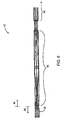
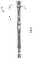
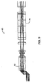
- Optical train 12 of endoscope 10 will generally include three lens systems: an objective lens system 30 in distal portion 18 (seen most clearly in Fig. 2 ), a relay lens system 40 in intermediate portion 22 (which will typically comprise a number of relay units 50, and which is seen most clearly in Figs. 3 and 4 ), and an ocular lens system 60 (shown in Figs. 4 and 10 ).
- the objective, relay, and ocular lens systems are typically designed independently and modularly, in the sense that the objective is designed to produce a first discrete image at a specific image point, the relay is designed to form a second at a second image point, and the ocular is designed to take the second image and manipulate it for viewing by a user.
- the invention merges the design of the objective-relay-ocular lens system, objective and ocular designs, the objective and relay lens systems, and/or the design of the relay and ocular lens systems.
- the product (h)(NA) a constant, dictated by the particular geometry (length, diameter, number of relays) of the endoscope/relay. This equation represents the limited ability of the endoscope/relay to collect and transfer image information.
- This product of h and NA remains constant for any location in an endoscope, where
- the effective NA of the endoscope shrinks, to keep the (h)(NA) endoscope throughput constant.
- the NA value is limited so as to avoid vignetting of the off-center axis portions of the image.
- the NA of an endoscope typically is not determined by the extent of the first relay lens aperture but rather by the aperture size inside the relay.
- This (h)(NA) product - which may also be referred to as the endoscope's "image information throughput" - provides a measure of the quality of image achievable with a particular endoscope. Aberrations in the image can limit the effective (h)(NA) product.
- the present invention enhances the product of (h)(NA) - either increasing the possible NA for a fixed h, or increasing the image size h capable of being throughputted for a fixed NA - and so increases the clarity of a given size image (of the object) produced at the proximal end of the endoscope. In short, the present invention results in the product (h)(NA) higher than previous endoscopes.
- endoscope 10 has an objective 30 constructed in such a way that a first intermediate image 32 falls not within an air space 34 between the objective and the relay 50.
- this first intermediate image 32 falls within the glass of the most proximal objective lens 36 which is extended proximal of the position of the first intermediate image 32 and into close proximity to the distal most surface 42 of relay 40.
- Causing the first intermediate image to coincide with glass instead of air, by, e.g., extending the most proximal objective lens portion, increases the ability of the endoscope to image a particular object and causes the endoscope to behave as if it had a much larger Numerical Aperture.
- the invention also permits the image to be less affected by dust or scratches on lens surfaces that would normally harm the image's quality and so affect the viewer's ability to detect small details in the image.
- the first intermediate image 32 is formed before the light rays have ceased expanding to their most extreme off-axis location (typically the endoscope's diameter). Because the light rays in the objective are still expanding when the image is formed, a larger image than that of a known endoscope is formed. However, because the light rays of the image are still expanding, it is desirable to cause the rays to converge (i) as if emanating from a larger object, and (ii) sufficiently so that all the light remains within the relay and no image information is lost.
- the most proximal objective lens surface 38 preferably serves this purpose.
- the most proximal surface 38 of the objective system 30 can be positioned very closely to the most distal surface 42 of the relay 40.
- the dimensions of the gap may be a function only of the desired curvature of the proximal most objective surface 38, which is curved sufficiently to preferably cause all of the light rays from the object and intermediate image to remain in the endoscope and not be lost. Due to the difference in index of refraction between glass and air and because of the curvature of that particular lens, the most proximal objective lens bends the light back into the endoscope.
- the endoscope's ability to carry an increased image size (formed form the still-diverging light rays in the objective) is improved.
- the curvature of the proximal most portion 38 of the objective and the particular index of refraction of the glass are chosen to balance the aberrations of the entire optical system and so enable successful transmission of the image through the relay 40 to the eyepiece.
- the extreme off axis rays of the image will preferably converge at points distal of the element capable of converging the still-diverging rays into relay 40.
- This task preferably is achieved with a combination of the curvature of the proximal-most face of the objective lens 38 in combination with the difference in refractive index between the glass of the objective lens and the air between the objective lens and relay lens.
- This converging function can also be performed by other optical elements, as would be obvious to one of skill in the art upon reading this disclosure, such as other glass or materials with a different refractive index.
- the exemplary endoscope 10 has a shaft diameter of about 5 mm, a length of about 400 mm, and 4 sets of relay rod lens units 50.
- the (NA)(h) product that can pass through the relay is also dependent on the length of the relay.
- the relay length gets longer, however, with the increase in relay lenses, there is a greater chance of introducing aberrations.
- the objective system of the present invention can have a larger (NA)(h) product so as to pass more of the image through the same length endoscope.
- NA NA
- the present invention permits an intermediate image having a larger size (and thus a larger information throughput through a certain length of relay) than is otherwise possible with known designs, perhaps by greater than 33%.
- the practical effect of increasing the throughput of information through an endoscope by increasing the value of the product (h)(NA) is to increase the amount of information about the object provided to the observer, thereby providing better image resolution and improved image brightness.
- a last intermediate image 62 is formed within glass of a lens 80 (shown in Fig. 10 ) of ocular system 60, thereby providing an alternative manner of correcting for distortions and field curvature and increasing the size of the image carried by the ocular portion of the endoscope.
- Ocular system 60 effectively corrects for different image aberrations such as distortion and field curvature without the use of optical components that would otherwise impair the performance or manufacturability of the endoscope.
- the last intermediate image 62 of the relay 50 is caused to coincide with the most distal, extended ocular lens 80 instead of in an air gap, as in image 52 between adjacent relay units 50.
- the most distal surface 66 of the ocular system 60 placed in close proximity to the most proximal surface of the relay optics, causes the image-forming rays to diverge.
- the image rays are then converged with other ocular surfaces to form the minimally or undistorted final image. Distortion and aberrations are removed with the latter ocular lens surfaces so the observer has a clear image to view.
- the distortions and aberrations are balanced and corrected in the objective lens system, the relay lens system, and the ocular lens system as an integral optical train combination.
- the image transmitted by the ocular lens system to the relay system will typically will contain distortions and aberrations which are ultimately balanced and corrected by the interaction with the optical components of the remainder of the optical train.
- the objective lens system of the invention is optimized to provide the maximum throughput of optical information through the endoscope. This permits better image resolution and improved image brightness, relative to a conventional endoscope in which the objective and ocular systems are independently balanced.
- the objective lens system 30 will capture an image and deliver an "unbalanced" image 32 (e.g., curved, enlarging image) through the relay lens system 40, 50 to the ocular lens system 60.
- an "unbalanced" image 32 e.g., curved, enlarging image
- the ocular lens system 60 the aberrations in the image 62 will be compensated for by the integral ocular lens system 60 ( Fig. 4 ) to produce the balanced final image.
- Embodying the invention in the ocular lens portion of the endoscope may be independent of, or in addition to, the objective-relay embodiment, shown in Fig. 2 .
- the image 62 can be manipulated in whatever manner is desired.
- the observer can view the image directly, or can cause the image to impinge - with appropriate magnification as desired - onto on or more CCDs for further image processing.
- relay 40 along intermediate portion 22 of endoscope 10 will typically comprise one or more relay lens units 50.
- Relay 40 generally forms an intermediate image 52 in gaps 54 between each pair of adjacent relay lens units 50.
- Typical endoscopes may include from 1 to about 20 relay units 50, and preferably from about 2 to about 6 relay units.
- Each unit 50 will preferably comprise a plurality of lenses, preferably including one or more rod lenses to reduce the number of relay units included to transfer the image the desired endoscope shaft length.
- Table 1 specifies the "recipe" or specific individual lenses of an exemplary monoscopic endoscope optical train. This radius, thickness, and diameter (which may be considered arbitrary) measurements in the table are in mm, while the indices of refraction of the lenses are determined by the glasses identified in the associated column.
- the specified glasses are available from a variety of sources including Schott Optical Glass Inc., of Duryea, Pennsylvania, and the listed glass identifiers will be recognized by such suppliers (and others of skill in the art).
- TABLE 1 Surf Type Radius Thickness Glass Diameter Conic Obj. Standard Infinity 38 47.38083 0 1. Standard Infinity 0.5 BK7 4 0 2. Standard Infinity 0.2 4 0 3. Standard Infinity 0.5 SK5 4 0 4.
- the objective lens system 30 will generally include the lens surfaces up to and including the twelfth numbered surface of Table 1, while the relay 40 will extend from there to the fiftieth numbered surface, as indicated.
- the proximal group of surfaces includes the ocular lens system 60, as described above.
- the aperture value is set to twice the first or marginal ray height throughout the chart.
- an alternative stereoscopic endoscope optical train 12' generally includes objective 30, relay 40, and ocular 60 lens systems similar to those described above.
- the stereoscopic optical system comprises two independent but identical optical trains.
- the enhanced image throughput of the present invention is a particular advantage with these two-channel systems.
- One or more of the distal-most lenses 72 of the objective 30, and one or more lenses of ocular 60 proximal of a splitter system 74 may be dedicated to a specific channel of such a stereoscopic system. Nonetheless, a first intermediate image 32 will preferably be contained within a lens of the objective system 30, and a last intermediate image 62 will preferably be contained within a lens 80 of the ocular system 60 as described above. In the exemplary embodiment of the stereoscopic endoscope optical train 12', a novel prism 88 helps to orient one or both of the images.
- ocular 60 will typically pass the image on to a camera for display on a monitor (typically using a stereoscopic camera and display system), or binocular eyepieces might be used for direct viewing.
- the present invention provides endoscopes having an ocular lens system with independently adjustable lens components.
- a user can independently calibrate each channel of a stereoscopic endoscope so as to manipulate the size, location, and orientation of an image of the object while reducing the amount of aberrations introduced into the final image.
- Both monoscopic and stereoscopic endoscopes need adjustments in diopters and magnification.
- the images relayed through the left channel and right channel must be stereomatched (e.g., centering images in the X-Y plane) as well as size matched and rotationally matched.
- known endoscopes do not allow for independent manipulation of these optical properties of the image.
- one of the optical properties of the image is interrelated with the other optical properties. Consequently, manipulation of one optical property (e.g., magnification) may detrimentally affect the other optical properties (e.g., diopters) and a large amount of aberrations may be introduced into the final displayed image.
- one optical property e.g., magnification
- other optical properties e.g., diopters
- the present invention provides monoscopic and stereoscopic endoscopes having an ocular lens system that allows for independent adjustments of the optical properties of the image which also reduces the amount of aberrations introduced into the relayed image.
- an adjustment is made to one optical property
- subsequent adjustments of the other optical properties of the image do not introduce appreciable changes into the previous adjustments.
- all adjustments to the endoscope are done only in the ocular lens system so that the user can focus on the target site without having to adjust the objective lens that is located at a distal end of the endoscope shaft.
- each of the lenses of the ocular lens system are disposed within a movable cell that allows a user to rotate and/or axially move the lenses to adjust the properties of the captured image. Some adjustments to the ocular can move the entire ocular lens system, while other adjustments move only selected cells and lenses relative to the rest of the lenses.
- the cell and lens components are designed to have a sensitivity that allows users to make fine adjustments to the rotational and axial position of the lenses needed for stereo imaging.
- some lenses and cells of the ocular system can be moved off of (e.g., orthogonal to) the optical axis.
- the endoscope comprises an elongate shaft 72 having a distal portion (not shown), an intermediate portion 74, and a proximal portion 76 that houses the ocular system.
- the distal portion of the endoscope is inserted into a body cavity to position an objective lens system ( Figs. 1 and 2 ) into close proximity of the target object O.
- the objective lens system, relay system 78, and ocular lens system 60 are positioned within an optical path within the endoscope such that an image of the object can be transmitted to a camera 24 that is optically coupled to the proximal end 16 of the endoscope ( Fig. 1 ).
- Camera 24 will typically have a charge-couple device (CCD) or the like, so that the camera can transmit image signals to allow a display D to reproduce the image O'.
- CCD charge-couple device
- Each side of the stereoscopic ocular lens system 60 includes a first lens 80, a second lens 82, a third lens 84, a fourth lens 86, and a prism 88 aligned with an optical axis 89 of that side of the endoscope.
- the lenses can be single or compound lenses.
- the lenses are disposed within moveable cells 90, 92, 94, 96 which can be rotatable, moveable along the optical axis 89 and/or moveable off of (orthogonal to) the optical axis.
- most embodiments of the endoscope comprise a fixed objective lens system and a fixed relay system so that all manipulation of the image is done in the proximal ocular lens system 60.
- the first lens 80 is a positive rod lens where the last relay unit forms the image 62 inside this rod lens 80. Similar to above, by forming the image within the lens, dust and other particles are prevented from degrading the image quality.
- Lens 82 is a negative lens, and as will be described below, can be moved off the optical axis 89 to adjust the X-Y positioning of the image.
- Lens 84 and lens 86 are positive singlet or compound lenses.
- Prism 88 is typically a dove prism or Abbe Konig prism. It should be appreciated, however, that other lens combinations are within the scope of the present invention.
- the ocular lens system 60 can be adjusted to manipulate the displayed image.
- the image 62 is formed within lens 80 and all of the lenses and cells are moved axially, relative to the image position to adjust the diopters (Step 100). Once the diopters has been set, the cell containing all the lenses 80, 82, 84, 86 is locked into position.
- Magnification of the image is adjusted by moving lenses 82, 84, 86 relative to the now stationary lens 80 (Step 102). Consequently, the diopters of the ocular system is maintained while lenses 82, 84, 86 are moved axially until the desired magnification has been achieved. Thereafter, the lenses 82, 84, 86 are locked in their axial position. If it is later desired to adjust magnification, the lenses 82, 84, 86 can be unlocked and moved axially to increase or decrease the magnification.
- lens 82 can be moved off the optical axis 89.
- moving the negative lens introduces the least amount of aberrations into the image.
- positive lens - negative lens - positive lens configuration is the preferred lens structure, it will be appreciated that other lens configurations are possible.
- negative lens 82 and positive lenses 84, 86 can be coupled together and the entire combination of lenses can be moved off of the optical axis to change X-Y positioning.
- such a combination does not provide the same image quality of the ocular system in which only lens 82 is moved orthogonally.
- the prism 88 can be rotated until the desired image orientation is achieved (Step 106).
- the prism is typically a dove prism, an Abbe Konig prism, or the like.
- one degree of rotation of the prism 88 can rotate the image by two degrees.
- the position and orientation of the lenses disposed within the left and right channels should be independently adjustable to allow the user to calibrate and "stereo match" the channels.
- the present invention provides a device for adjusting the stereo line of convergence between the two optical channels.
- the present invention sets the stereo line of convergence that is 50 mm from the distal tip of the stereoscopic endoscope. While the following discussion focuses on the exemplary embodiment, it should be appreciated that the concepts of the present invention can be modified to work with endoscopes having other working distances.
- a wedge 110 is used to offset the light rays 112 through the proximal end of prism 88.
- Wedge 110 can be added onto the proximal end of the dove prism or Abbe Konig prism to refract the light 112 to create the stereo line convergence ( Fig. 14A ).
- the proximal end of the prism 88 can be shaped to form the proximal, angled, wedge surface ( Fig. 14B ). While not shown, the wedges 110 in the two channels will mirror each other across the longitudinal axis of the stereo endoscope.
- lenses 84 and 86 move together, it may be possible to combine lenses 84, 86 into one integral compound lens 87 ( Fig. 15 ).
- lenses 82, 84, 86 can all be moved orthogonal to the optical axis ( Fig. 16 ).
- lens 82, 84, and 86 into a single lens 89 that is axially moveable and orthogonally moveable so that the single lens can be moved to control magnification and X-Y positioning ( Fig. 17 ).
- lens 82, 84, and 86 may even be possible to leave lens 82 within the optical path and move lens 84 and/or 86 orthogonally to adjust the X-Y positioning of the image ( Fig. 18 ).
- the above described alternatives while viable, introduce additional aberrations into the image.
Landscapes
- Physics & Mathematics (AREA)
- Health & Medical Sciences (AREA)
- Life Sciences & Earth Sciences (AREA)
- Optics & Photonics (AREA)
- Surgery (AREA)
- General Physics & Mathematics (AREA)
- Biomedical Technology (AREA)
- General Health & Medical Sciences (AREA)
- Pathology (AREA)
- Engineering & Computer Science (AREA)
- Nuclear Medicine, Radiotherapy & Molecular Imaging (AREA)
- Heart & Thoracic Surgery (AREA)
- Medical Informatics (AREA)
- Molecular Biology (AREA)
- Animal Behavior & Ethology (AREA)
- Radiology & Medical Imaging (AREA)
- Public Health (AREA)
- Veterinary Medicine (AREA)
- Biophysics (AREA)
- Astronomy & Astrophysics (AREA)
- Instruments For Viewing The Inside Of Hollow Bodies (AREA)
- Endoscopes (AREA)
- Lenses (AREA)
Claims (14)
- Verfahren zum Manipulieren eines Bildes, das von einer stereoskopischen Endoskopabbildungsvorrichtung erfasst wurde, wobei das Verfahren Folgendes umfasst:Einstellen (100) eine Dioptrie des erfassten Bildes durch axiales Bewegen einer Vielzahl von Linsen (80, 82, 84, 86), die in einem Okularsystem (60) innerhalb der genannten stereoskopischen Endoskopabbildungsvorrichtung enthalten sind; unabhängiges Verändern (102) der Vergrößerung eines Bildes unter Verwendung von mindestens einer der genannten Vielzahl von Linsen (80, 82, 84, 86), ohne die Dioptrien signifikant zu beeinflussen;Einstellen (104) der X-Y-Positionierung des Bildes unter Verwendung von mindestens einer der genannten Vielzahl von Linsen (80, 82, 84, 86), wobei mindestens eine der Linsen (82, 84, 86) von einer optischen Achse (89) des Okularsystems (60) weg bewegt wird, ohne Abweichungen einzuführen oder die Dioptrien und die Vergrößerung zu beeinträchtigen; undDrehen (106) einer Orientierung des erfassten Bildes durch das Okularsystem (60), wobei das Drehen die Dioptrien, die Vergrößerung und die X-Y-Positionierung des erfassten Bildes nicht beeinflusst.
- Verfahren nach Anspruch 1, wobei die Vielzahl von Linsen (80, 82, 84, 86) eine erste Linse, eine zweite Linse und eine dritte Linse umfasst, wobei das unabhängige Verändern (102) der Vergrößerung umfasst, dass die erste Linse stationär gehalten wird und die zweite und dritte Linse des Okularsystems (60) axial bewegt wird.
- Verfahren nach Anspruch 1, wobei das Einstellen (104) der X-Y-Positionierung das Bewegen einer Linse des Okularsystems (60) orthogonal zur optischen Achse (89) des Okularsystems (60) umfasst.
- Verfahren nach Anspruch 1, wobei das Drehen (106) des Bildes das Drehen eines Prismas (88) des Okularsystems (60) umfasst.
- Verfahren nach Anspruch 1, wobei die Vielzahl von Linsen (80, 82, 84, 86) mindestens eine erste Linse, eine zweite Linse und eine dritte Linse umfasst und das Okularsystem (60) ferner ein Prisma (88) umfasst, wobei die Vielzahl von Linsen (80, 82, 84, 86) und das Prisma (88) in einem optischen Pfad des Okularsystems (60) angeordnet sind,
wobei das unabhängige Verändern der Vergrößerung ferner Folgendes umfasst: Aufrechterhalten der Position der ersten Linse und Bewegen der zweiten und dritten Linse, um die Vergrößerung des Bildes einzustellen (102);
wobei das Einstellen (104) der X-Y-Positionierung des Bildes ferner Folgendes umfasst: Einstellen (104) einer orthogonalen Anordnung der zweiten Linse, um die X-Y-Position des Bildes einzustellen; und
wobei das Drehen (106) der Orientierung des erfassten Bildes ferner das Drehen (106) des Prismas (88) umfasst, um die gedrehte Orientierung des Bildes einzustellen. - Verfahren nach Anspruch 5, wobei das Okularsystem (60) ferner eine vierte Linse umfasst und das Verfahren ferner das Bewegen der vierten Linse mit der dritten Linse umfasst.
- Verfahren nach Anspruch 5, das ferner das Beugen von Lichtstrahlen mit einem Keil umfasst, um eine Stereo-Konvergenzlinie zu bilden.
- Verfahren nach Anspruch 5, wobei die zweite Linse eine negative Linse (82) ist.
- Verfahren nach Anspruch 8, wobei die erste Linse und die dritte Linse positive Linsen (84, 86) sind.
- Stereoskopisches Endoskop, das Folgendes umfasst:einen ersten Kanal, der Folgendes umfasst: ein erstes Objektivlinsensystem, ein erstes Übertragungssystem, ein erstes Okularlinsensystem und einen ersten optischen Pfad, wobei das erste Objektivlinsensystem durch das erste Übertragungssystem mit dem ersten Okularlinsensystem optisch gekoppelt ist und sich der erste optische Pfad durch das erste Objektivlinsensystem, das erste Übertragungssystem und das erste Okularlinsensystem erstreckt;einen zweiten Kanal, der Folgendes umfasst: ein zweites Objektivlinsensystem, ein zweites Übertragungssystem, ein zweites Okularlinsensystem und einen zweiten optischen Pfad, wobei das zweite Objektivlinsensystem durch das zweite Übertragungssystem mit dem zweiten Okularlinsensystem optisch gekoppelt ist und sich der zweite optische Pfad durch das zweite Objektivlinsensystem, das zweite Übertragungssystem und das zweite Okularlinsensystem erstreckt;wobei das erste Okularlinsensystem und das zweite Okularlinsensystem jeweils Folgendes umfasst: eine erste positive Linse, eine zweite positive Linse und eine negative Linse (82), wobei die erste und zweite positive Linse (84, 86) und die negative Linse (82) des ersten Okularsystems in dem ersten optischen Pfad angeordnet sind, wobei die erste und zweite positive Linse (84, 86) und die negative Linse (82) der zweiten Okularsysteme in dem zweiten optischen Pfad angeordnet sind, und
wobei die negative Linse (82) in dem ersten optischen Pfad dafür konfiguriert ist, dass sie von dem ersten optischen Pfad weg bewegt werden kann, und die negative Linse (82) in dem zweiten optischen Pfad dafür konfiguriert ist, dass sie von dem zweiten optischen Pfad weg bewegt werden kann, um eine Stereo-Übereinstimmung zwischen dem ersten Kanal und dem zweiten Kanal zu erreichen. - Stereoskopisches Endoskop nach Anspruch 10, wobei die Bewegung der negativen Linse (82) Abweichungen von nicht mehr als 1 % einführt.
- Stereoskopisches Endoskop nach Anspruch 10, wobei die negative Linse (82) in dem ersten optischen Pfad dafür konfiguriert ist, dass sie in einer Richtung orthogonal zu dem ersten optischen Pfad bewegt werden kann, und die negative Linse (82) in dem zweiten optischen Pfad dafür konfiguriert ist, dass sie in einer Richtung orthogonal zu dem zweiten optischen Pfad bewegt werden kann.
- Stereoskopisches Endoskop nach Anspruch 10, wobei das erste Okularlinsensystem und das zweite Okularlinsensystem jeweils einen Keil umfasst, der Lichtstrahlen beugt, um eine Stereo-Konvergenzlinie zu bilden.
- Stereoskopisches Endoskop nach Anspruch 10, wobei das erste und zweite Übertragunglinsensystem jeweils eine Vielzahl von axial getrennten Übertragungeinheiten umfasst, wobei jede der Vielzahl von axial getrennten Übertragungeinheiten einen axial symmetrischen Satz von Übertragunglinsen umfasst, wobei ein optisches Element zwischen jedem Paar von benachbarten Übertragungeinheiten der Vielzahl von axial getrennten Übertragungeinheiten angeordnet ist, so dass ein Zwischenbild in dem optischen Element gebildet wird.
Applications Claiming Priority (4)
| Application Number | Priority Date | Filing Date | Title |
|---|---|---|---|
| US17610100P | 2000-01-14 | 2000-01-14 | |
| US68092200A | 2000-10-06 | 2000-10-06 | |
| US09/689,444 US6817975B1 (en) | 2000-01-14 | 2000-10-12 | Endoscope |
| EP20010906541 EP1250081B1 (de) | 2000-01-14 | 2001-01-12 | Endoskop |
Related Parent Applications (2)
| Application Number | Title | Priority Date | Filing Date |
|---|---|---|---|
| EP20010906541 Division EP1250081B1 (de) | 2000-01-14 | 2001-01-12 | Endoskop |
| EP20010906541 Division-Into EP1250081B1 (de) | 2000-01-14 | 2001-01-12 | Endoskop |
Publications (2)
| Publication Number | Publication Date |
|---|---|
| EP2105083A1 EP2105083A1 (de) | 2009-09-30 |
| EP2105083B1 true EP2105083B1 (de) | 2016-08-10 |
Family
ID=33422527
Family Applications (1)
| Application Number | Title | Priority Date | Filing Date |
|---|---|---|---|
| EP09165193.5A Expired - Lifetime EP2105083B1 (de) | 2000-01-14 | 2001-01-12 | Endoskop |
Country Status (2)
| Country | Link |
|---|---|
| US (1) | US6817975B1 (de) |
| EP (1) | EP2105083B1 (de) |
Families Citing this family (57)
| Publication number | Priority date | Publication date | Assignee | Title |
|---|---|---|---|---|
| EP1250081B1 (de) * | 2000-01-14 | 2015-04-29 | Intuitive Surgical Operations, Inc. | Endoskop |
| US9155544B2 (en) * | 2002-03-20 | 2015-10-13 | P Tech, Llc | Robotic systems and methods |
| US7960935B2 (en) | 2003-07-08 | 2011-06-14 | The Board Of Regents Of The University Of Nebraska | Robotic devices with agent delivery components and related methods |
| US7042184B2 (en) | 2003-07-08 | 2006-05-09 | Board Of Regents Of The University Of Nebraska | Microrobot for surgical applications |
| JP5227312B2 (ja) * | 2006-05-17 | 2013-07-03 | ムーア,ケント | 患者の上気道の測定値を得るためのシステム及び立体ビデオ内視鏡の作動方法 |
| US8679096B2 (en) | 2007-06-21 | 2014-03-25 | Board Of Regents Of The University Of Nebraska | Multifunctional operational component for robotic devices |
| US9579088B2 (en) | 2007-02-20 | 2017-02-28 | Board Of Regents Of The University Of Nebraska | Methods, systems, and devices for surgical visualization and device manipulation |
| CA2655964C (en) | 2006-06-22 | 2014-10-28 | Board Of Regents Of The University Of Nebraska | Magnetically coupleable robotic devices and related methods |
| IL188169A (en) | 2006-12-18 | 2011-06-30 | Visionsense Ltd | High resolution endoscope |
| US8556807B2 (en) * | 2006-12-21 | 2013-10-15 | Intuitive Surgical Operations, Inc. | Hermetically sealed distal sensor endoscope |
| US8814779B2 (en) | 2006-12-21 | 2014-08-26 | Intuitive Surgical Operations, Inc. | Stereoscopic endoscope |
| EP3078344B1 (de) | 2007-07-12 | 2020-02-26 | Board of Regents of the University of Nebraska | Betätigung in robotischen vorrichtungen |
| EP2178431A4 (de) | 2007-08-15 | 2017-01-18 | Board of Regents of the University of Nebraska | Medizinische inflations-, aufbringungs- und verabreichungsvorrichtungen sowie entsprechende verfahren |
| JP5475662B2 (ja) | 2007-08-15 | 2014-04-16 | ボード オブ リージェンツ オブ ザ ユニバーシティ オブ ネブラスカ | モジュール式およびセグメント化医療装置ならびに関連するシステム |
| EP2512754A4 (de) | 2009-12-17 | 2016-11-30 | Univ Nebraska | Modulare und kooperative medizinische vorrichtungen sowie entsprechende systeme und verfahren |
| JP2014529414A (ja) | 2010-08-06 | 2014-11-13 | ボード オブ リージェンツ オブ ザ ユニバーシティ オブ ネブラスカ | 自然開口部手術用材料の取扱または送達のための方法およびシステム |
| US9486189B2 (en) | 2010-12-02 | 2016-11-08 | Hitachi Aloka Medical, Ltd. | Assembly for use with surgery system |
| EP3714821A1 (de) | 2011-06-10 | 2020-09-30 | Board of Regents of the University of Nebraska | Chirurgisches greifinstrument |
| US9089353B2 (en) | 2011-07-11 | 2015-07-28 | Board Of Regents Of The University Of Nebraska | Robotic surgical devices, systems, and related methods |
| EP2882330B1 (de) | 2011-10-03 | 2020-05-13 | Board of Regents of the University of Nebraska | Robotische chirurgische vorrichtungen und systeme |
| CA3098065C (en) | 2012-01-10 | 2023-10-31 | Board Of Regents Of The University Of Nebraska | Methods, systems, and devices for surgical access and insertion |
| CA2871149C (en) | 2012-05-01 | 2020-08-25 | Board Of Regents Of The University Of Nebraska | Single site robotic device and related systems and methods |
| WO2013191773A1 (en) | 2012-06-22 | 2013-12-27 | Board Of Regents Of The University Of Nebraska | Local Control Robotic Surgical Devices and Related Methods |
| US9642606B2 (en) | 2012-06-27 | 2017-05-09 | Camplex, Inc. | Surgical visualization system |
| US8882662B2 (en) | 2012-06-27 | 2014-11-11 | Camplex, Inc. | Interface for viewing video from cameras on a surgical visualization system |
| CA2880622C (en) | 2012-08-08 | 2021-01-12 | Board Of Regents Of The University Of Nebraska | Robotic surgical devices, systems and related methods |
| US12295680B2 (en) | 2012-08-08 | 2025-05-13 | Board Of Regents Of The University Of Nebraska | Robotic surgical devices, systems and related methods |
| US9770305B2 (en) | 2012-08-08 | 2017-09-26 | Board Of Regents Of The University Of Nebraska | Robotic surgical devices, systems, and related methods |
| WO2014160086A2 (en) | 2013-03-14 | 2014-10-02 | Board Of Regents Of The University Of Nebraska | Methods, systems, and devices relating to robotic surgical devices, end effectors, and controllers |
| CA2906672C (en) | 2013-03-14 | 2022-03-15 | Board Of Regents Of The University Of Nebraska | Methods, systems, and devices relating to force control surgical systems |
| JP2016513556A (ja) | 2013-03-15 | 2016-05-16 | ボード オブ リージェンツ オブ ザ ユニバーシティ オブ ネブラスカ | ロボット外科的デバイス、システム、および関連する方法 |
| EP2999414B1 (de) | 2013-05-21 | 2018-08-08 | Camplex, Inc. | Chirurgische visualisierungssysteme |
| US10966700B2 (en) | 2013-07-17 | 2021-04-06 | Virtual Incision Corporation | Robotic surgical devices, systems and related methods |
| EP3046458B1 (de) | 2013-09-20 | 2020-10-21 | Camplex, Inc. | Chirurgische visualisierungssysteme |
| JP2017509019A (ja) * | 2014-03-04 | 2017-03-30 | ノバダック テクノロジーズ インコーポレイテッド | 広域撮像のためのリレーレンズシステム |
| KR102054483B1 (ko) | 2014-03-04 | 2019-12-10 | 노바다크 테크놀러지즈 유엘씨 | 공간 및 스펙트럼 필터 어퍼처 및 그를 포함한 광학 이미징 시스템 |
| JP6710199B2 (ja) | 2014-09-12 | 2020-06-17 | ボード オブ リージェンツ オブ ザ ユニバーシティ オブ ネブラスカ | クイックリリースエンドエフェクターおよび関連するシステムおよび方法 |
| US10376322B2 (en) | 2014-11-11 | 2019-08-13 | Board Of Regents Of The University Of Nebraska | Robotic device with compact joint design and related systems and methods |
| US10702353B2 (en) | 2014-12-05 | 2020-07-07 | Camplex, Inc. | Surgical visualizations systems and displays |
| IL236418A (en) | 2014-12-23 | 2016-07-31 | Visionsense Ltd | Stereo endoscope with tiltable, rotatable view |
| WO2016154589A1 (en) | 2015-03-25 | 2016-09-29 | Camplex, Inc. | Surgical visualization systems and displays |
| CN114027986B (zh) | 2015-08-03 | 2024-06-14 | 内布拉斯加大学董事会 | 机器人手术装置系统及相关方法 |
| BR112018003903A2 (pt) | 2015-08-31 | 2018-09-25 | Novadaq Tech Ulc | sistema, método para filtrar luz polarizada e kit para usar com um sistema que tem lente birrefringente |
| DE102015118250B4 (de) * | 2015-10-26 | 2019-02-28 | Leica Camera Ag | Foto-Adapter |
| WO2017091704A1 (en) | 2015-11-25 | 2017-06-01 | Camplex, Inc. | Surgical visualization systems and displays |
| CN114098975A (zh) | 2016-05-18 | 2022-03-01 | 虚拟切割有限公司 | 机器人外科装置、系统及相关方法 |
| CA3034671A1 (en) | 2016-08-25 | 2018-03-01 | Shane Farritor | Quick-release tool coupler and related systems and methods |
| CN114872081B (zh) | 2016-08-30 | 2025-01-17 | 内布拉斯加大学董事会 | 具有紧凑型关节设计和附加自由度的机器人装置及相关系统和方法 |
| US11357595B2 (en) | 2016-11-22 | 2022-06-14 | Board Of Regents Of The University Of Nebraska | Gross positioning device and related systems and methods |
| JP7099728B2 (ja) | 2016-11-29 | 2022-07-12 | バーチャル インシジョン コーポレイション | ユーザの存在検出機能を備えたユーザコントローラ、関連システムおよび方法 |
| US10722319B2 (en) | 2016-12-14 | 2020-07-28 | Virtual Incision Corporation | Releasable attachment device for coupling to medical devices and related systems and methods |
| US10918455B2 (en) | 2017-05-08 | 2021-02-16 | Camplex, Inc. | Variable light source |
| US11051894B2 (en) | 2017-09-27 | 2021-07-06 | Virtual Incision Corporation | Robotic surgical devices with tracking camera technology and related systems and methods |
| EP4461479A3 (de) | 2018-01-05 | 2025-01-22 | Board of Regents of the University of Nebraska | Einarmige robotische vorrichtung mit kompaktem gelenkentwurf sowie zugehörige systeme |
| EP3908171A4 (de) | 2019-01-07 | 2022-09-14 | Virtual Incision Corporation | Robotisiertes assistiertes chirurgisches system und zugehörige vorrichtungen und verfahren |
| EP4175576A4 (de) | 2020-07-06 | 2024-08-07 | Virtual Incision Corporation | Positionierungssystem für chirurgischen roboter sowie zugehörige vorrichtungen und verfahren |
| DE102022102804A1 (de) | 2022-02-07 | 2023-08-10 | avateramedical GmBH | Endoskop für die laparoskopische Chirurgie |
Citations (5)
| Publication number | Priority date | Publication date | Assignee | Title |
|---|---|---|---|---|
| GB2068581A (en) * | 1979-12-26 | 1981-08-12 | Fuji Photo Optical Co Ltd | Optical system for endoscopes |
| EP0066374A1 (de) * | 1981-05-29 | 1982-12-08 | Olympus Optical Co., Ltd. | Endoskope |
| WO1994013189A1 (en) * | 1992-12-17 | 1994-06-23 | Paul Stuart Kempf And Pilar Moreno Kempf Family Trust | 3-d endoscope apparatus |
| US5749830A (en) * | 1993-12-03 | 1998-05-12 | Olympus Optical Co., Ltd. | Fluorescent endoscope apparatus |
| US5852511A (en) * | 1993-10-20 | 1998-12-22 | Olympus Optical Co. Ltd | Optical system for non-flexible endoscopes |
Family Cites Families (16)
| Publication number | Priority date | Publication date | Assignee | Title |
|---|---|---|---|---|
| DE3527393A1 (de) | 1985-07-31 | 1987-02-05 | Wolf Gmbh Richard | Endoskopoptik |
| DE3734917A1 (de) | 1987-10-15 | 1989-04-27 | Wolf Gmbh Richard | Okularaufsatz fuer ein endoskop |
| JP2761726B2 (ja) | 1988-03-11 | 1998-06-04 | 旭光学工業株式会社 | 内視鏡の接眼装置 |
| US4969708A (en) | 1989-07-27 | 1990-11-13 | Leiner Dennis C | Fiberoptic endoscope |
| JP3078085B2 (ja) | 1991-03-26 | 2000-08-21 | オリンパス光学工業株式会社 | 画像処理装置および画像処理方法 |
| US5341240A (en) * | 1992-02-06 | 1994-08-23 | Linvatec Corporation | Disposable endoscope |
| DE4243127A1 (de) | 1992-12-19 | 1994-06-23 | Gautschi Electro Fours Sa | Verfahren und Vorrichtung zur Wärmebehandlung von Wärmgut in einem Industrieofen |
| JP3220538B2 (ja) | 1992-12-24 | 2001-10-22 | オリンパス光学工業株式会社 | 立体視内視鏡及び立体視内視鏡装置 |
| US5588948A (en) | 1993-02-17 | 1996-12-31 | Olympus Optical Co. Ltd. | Stereoscopic endoscope |
| DE9402336U1 (de) | 1994-02-12 | 1994-03-31 | Richard Wolf Gmbh, 75438 Knittlingen | Stereo-Endoskop |
| US5743846A (en) | 1994-03-17 | 1998-04-28 | Olympus Optical Co., Ltd. | Stereoscopic endoscope objective lens system having a plurality of front lens groups and one common rear lens group |
| JPH0829701A (ja) | 1994-07-18 | 1996-02-02 | Olympus Optical Co Ltd | 立体視内視鏡システム |
| US5833596A (en) * | 1995-04-14 | 1998-11-10 | Vipera Systems, Inc. | Endoscope for imaging infrared emissions within the range of 2 to 14 microns |
| US5980453A (en) | 1996-02-22 | 1999-11-09 | Precision Optics Corporation | Endoscope with low distortion |
| DE19631840A1 (de) | 1996-08-07 | 1998-02-12 | Winter & Ibe Olympus | Endoskopoptik |
| JPH1090603A (ja) | 1996-09-18 | 1998-04-10 | Olympus Optical Co Ltd | 内視鏡光学系 |
-
2000
- 2000-10-12 US US09/689,444 patent/US6817975B1/en not_active Expired - Lifetime
-
2001
- 2001-01-12 EP EP09165193.5A patent/EP2105083B1/de not_active Expired - Lifetime
Patent Citations (5)
| Publication number | Priority date | Publication date | Assignee | Title |
|---|---|---|---|---|
| GB2068581A (en) * | 1979-12-26 | 1981-08-12 | Fuji Photo Optical Co Ltd | Optical system for endoscopes |
| EP0066374A1 (de) * | 1981-05-29 | 1982-12-08 | Olympus Optical Co., Ltd. | Endoskope |
| WO1994013189A1 (en) * | 1992-12-17 | 1994-06-23 | Paul Stuart Kempf And Pilar Moreno Kempf Family Trust | 3-d endoscope apparatus |
| US5852511A (en) * | 1993-10-20 | 1998-12-22 | Olympus Optical Co. Ltd | Optical system for non-flexible endoscopes |
| US5749830A (en) * | 1993-12-03 | 1998-05-12 | Olympus Optical Co., Ltd. | Fluorescent endoscope apparatus |
Also Published As
| Publication number | Publication date |
|---|---|
| US6817975B1 (en) | 2004-11-16 |
| EP2105083A1 (de) | 2009-09-30 |
Similar Documents
| Publication | Publication Date | Title |
|---|---|---|
| EP2105083B1 (de) | Endoskop | |
| US9039609B2 (en) | Endoscope | |
| JP4093503B2 (ja) | 立体視内視鏡 | |
| US20050154256A1 (en) | Convergence optics for stereoscopic imaging systems | |
| US7768701B2 (en) | Three-dimensional medical imaging apparatus | |
| US5222477A (en) | Endoscope or borescope stereo viewing system | |
| US9192286B2 (en) | Stereoscopic visualization system | |
| JPH0882766A (ja) | 立体視内視鏡 | |
| RU2764081C2 (ru) | Объектив камеры для эндоскопа и эндоскоп | |
| US6155973A (en) | Universal endoscope video adaptor with zoom | |
| US6113533A (en) | Endoscope video adapter with zoom | |
| JPH0856891A (ja) | 立体視硬性内視鏡 | |
| EP0681809A1 (de) | Stereo-Abbildungsanordnung für Endoskopsonde | |
| WO1997027798A1 (en) | Stereoscopic endoscope | |
| US6898022B2 (en) | Stereo optical system pair for stereo endoscope system | |
| US20020085272A1 (en) | Rigid video-endoscope system | |
| JPH08122666A (ja) | 立体視内視鏡 | |
| JPH09248276A (ja) | 視野方向可変硬性鏡装置 | |
| JPH06167658A (ja) | 立体内視鏡 | |
| Xiang et al. | The optical design of stereo endoscope | |
| US20220346635A1 (en) | Endoscope | |
| JP3479123B2 (ja) | 複数画像立体視装置 | |
| Bonnet et al. | Microsurgery: Micro-and mini-instruments | |
| HK40001866B (zh) | 用於内窥镜的相机物镜和内窥镜 | |
| HK40001866A (en) | Camera objective lens for an endoscope and endoscope |
Legal Events
| Date | Code | Title | Description |
|---|---|---|---|
| PUAI | Public reference made under article 153(3) epc to a published international application that has entered the european phase |
Free format text: ORIGINAL CODE: 0009012 |
|
| AC | Divisional application: reference to earlier application |
Ref document number: 1250081 Country of ref document: EP Kind code of ref document: P |
|
| AK | Designated contracting states |
Kind code of ref document: A1 Designated state(s): AT BE CH CY DE DK ES FI FR GB GR IE IT LI LU MC NL PT SE TR |
|
| RAP1 | Party data changed (applicant data changed or rights of an application transferred) |
Owner name: INTUITIVE SURGICAL, INC. |
|
| 17P | Request for examination filed |
Effective date: 20100107 |
|
| 17Q | First examination report despatched |
Effective date: 20100212 |
|
| RAP1 | Party data changed (applicant data changed or rights of an application transferred) |
Owner name: INTUITIVE SURGICAL OPERATIONS, INC. |
|
| REG | Reference to a national code |
Ref country code: DE Ref legal event code: R079 Ref document number: 60150049 Country of ref document: DE Free format text: PREVIOUS MAIN CLASS: A61B0001002000 Ipc: A61B0001000000 |
|
| GRAP | Despatch of communication of intention to grant a patent |
Free format text: ORIGINAL CODE: EPIDOSNIGR1 |
|
| RIC1 | Information provided on ipc code assigned before grant |
Ipc: G02B 23/24 20060101ALI20150622BHEP Ipc: A61B 1/00 20060101AFI20150622BHEP Ipc: G02B 25/00 20060101ALI20150622BHEP Ipc: A61B 1/055 20060101ALI20150622BHEP Ipc: A61B 1/04 20060101ALI20150622BHEP |
|
| INTG | Intention to grant announced |
Effective date: 20150720 |
|
| RIN1 | Information on inventor provided before grant (corrected) |
Inventor name: BRAXMEIER, WOLFGANG Inventor name: FARR, MINA |
|
| RIN1 | Information on inventor provided before grant (corrected) |
Inventor name: BRAXMEIER, WOLFGANG Inventor name: FARR, MINA |
|
| INTG | Intention to grant announced |
Effective date: 20160226 |
|
| GRAS | Grant fee paid |
Free format text: ORIGINAL CODE: EPIDOSNIGR3 |
|
| GRAA | (expected) grant |
Free format text: ORIGINAL CODE: 0009210 |
|
| AC | Divisional application: reference to earlier application |
Ref document number: 1250081 Country of ref document: EP Kind code of ref document: P |
|
| AK | Designated contracting states |
Kind code of ref document: B1 Designated state(s): AT BE CH CY DE DK ES FI FR GB GR IE IT LI LU MC NL PT SE TR |
|
| REG | Reference to a national code |
Ref country code: GB Ref legal event code: FG4D |
|
| REG | Reference to a national code |
Ref country code: CH Ref legal event code: EP Ref country code: AT Ref legal event code: REF Ref document number: 818173 Country of ref document: AT Kind code of ref document: T Effective date: 20160815 |
|
| REG | Reference to a national code |
Ref country code: IE Ref legal event code: FG4D |
|
| REG | Reference to a national code |
Ref country code: DE Ref legal event code: R096 Ref document number: 60150049 Country of ref document: DE |
|
| REG | Reference to a national code |
Ref country code: NL Ref legal event code: MP Effective date: 20160810 |
|
| REG | Reference to a national code |
Ref country code: AT Ref legal event code: MK05 Ref document number: 818173 Country of ref document: AT Kind code of ref document: T Effective date: 20160810 |
|
| REG | Reference to a national code |
Ref country code: FR Ref legal event code: PLFP Year of fee payment: 17 |
|
| PG25 | Lapsed in a contracting state [announced via postgrant information from national office to epo] |
Ref country code: NL Free format text: LAPSE BECAUSE OF FAILURE TO SUBMIT A TRANSLATION OF THE DESCRIPTION OR TO PAY THE FEE WITHIN THE PRESCRIBED TIME-LIMIT Effective date: 20160810 Ref country code: IT Free format text: LAPSE BECAUSE OF FAILURE TO SUBMIT A TRANSLATION OF THE DESCRIPTION OR TO PAY THE FEE WITHIN THE PRESCRIBED TIME-LIMIT Effective date: 20160810 Ref country code: FI Free format text: LAPSE BECAUSE OF FAILURE TO SUBMIT A TRANSLATION OF THE DESCRIPTION OR TO PAY THE FEE WITHIN THE PRESCRIBED TIME-LIMIT Effective date: 20160810 |
|
| PG25 | Lapsed in a contracting state [announced via postgrant information from national office to epo] |
Ref country code: AT Free format text: LAPSE BECAUSE OF FAILURE TO SUBMIT A TRANSLATION OF THE DESCRIPTION OR TO PAY THE FEE WITHIN THE PRESCRIBED TIME-LIMIT Effective date: 20160810 Ref country code: SE Free format text: LAPSE BECAUSE OF FAILURE TO SUBMIT A TRANSLATION OF THE DESCRIPTION OR TO PAY THE FEE WITHIN THE PRESCRIBED TIME-LIMIT Effective date: 20160810 Ref country code: ES Free format text: LAPSE BECAUSE OF FAILURE TO SUBMIT A TRANSLATION OF THE DESCRIPTION OR TO PAY THE FEE WITHIN THE PRESCRIBED TIME-LIMIT Effective date: 20160810 Ref country code: PT Free format text: LAPSE BECAUSE OF FAILURE TO SUBMIT A TRANSLATION OF THE DESCRIPTION OR TO PAY THE FEE WITHIN THE PRESCRIBED TIME-LIMIT Effective date: 20161212 Ref country code: GR Free format text: LAPSE BECAUSE OF FAILURE TO SUBMIT A TRANSLATION OF THE DESCRIPTION OR TO PAY THE FEE WITHIN THE PRESCRIBED TIME-LIMIT Effective date: 20161111 |
|
| REG | Reference to a national code |
Ref country code: DE Ref legal event code: R097 Ref document number: 60150049 Country of ref document: DE |
|
| PG25 | Lapsed in a contracting state [announced via postgrant information from national office to epo] |
Ref country code: DK Free format text: LAPSE BECAUSE OF FAILURE TO SUBMIT A TRANSLATION OF THE DESCRIPTION OR TO PAY THE FEE WITHIN THE PRESCRIBED TIME-LIMIT Effective date: 20160810 Ref country code: BE Free format text: LAPSE BECAUSE OF FAILURE TO SUBMIT A TRANSLATION OF THE DESCRIPTION OR TO PAY THE FEE WITHIN THE PRESCRIBED TIME-LIMIT Effective date: 20160810 |
|
| PLBE | No opposition filed within time limit |
Free format text: ORIGINAL CODE: 0009261 |
|
| STAA | Information on the status of an ep patent application or granted ep patent |
Free format text: STATUS: NO OPPOSITION FILED WITHIN TIME LIMIT |
|
| 26N | No opposition filed |
Effective date: 20170511 |
|
| REG | Reference to a national code |
Ref country code: CH Ref legal event code: PL |
|
| PG25 | Lapsed in a contracting state [announced via postgrant information from national office to epo] |
Ref country code: MC Free format text: LAPSE BECAUSE OF FAILURE TO SUBMIT A TRANSLATION OF THE DESCRIPTION OR TO PAY THE FEE WITHIN THE PRESCRIBED TIME-LIMIT Effective date: 20160810 |
|
| PG25 | Lapsed in a contracting state [announced via postgrant information from national office to epo] |
Ref country code: CH Free format text: LAPSE BECAUSE OF NON-PAYMENT OF DUE FEES Effective date: 20170131 Ref country code: LI Free format text: LAPSE BECAUSE OF NON-PAYMENT OF DUE FEES Effective date: 20170131 |
|
| REG | Reference to a national code |
Ref country code: IE Ref legal event code: MM4A |
|
| PG25 | Lapsed in a contracting state [announced via postgrant information from national office to epo] |
Ref country code: LU Free format text: LAPSE BECAUSE OF NON-PAYMENT OF DUE FEES Effective date: 20170112 |
|
| REG | Reference to a national code |
Ref country code: FR Ref legal event code: PLFP Year of fee payment: 18 |
|
| PG25 | Lapsed in a contracting state [announced via postgrant information from national office to epo] |
Ref country code: IE Free format text: LAPSE BECAUSE OF NON-PAYMENT OF DUE FEES Effective date: 20170112 |
|
| PG25 | Lapsed in a contracting state [announced via postgrant information from national office to epo] |
Ref country code: CY Free format text: LAPSE BECAUSE OF NON-PAYMENT OF DUE FEES Effective date: 20160810 |
|
| PG25 | Lapsed in a contracting state [announced via postgrant information from national office to epo] |
Ref country code: TR Free format text: LAPSE BECAUSE OF FAILURE TO SUBMIT A TRANSLATION OF THE DESCRIPTION OR TO PAY THE FEE WITHIN THE PRESCRIBED TIME-LIMIT Effective date: 20160810 |
|
| PGFP | Annual fee paid to national office [announced via postgrant information from national office to epo] |
Ref country code: GB Payment date: 20200129 Year of fee payment: 20 Ref country code: DE Payment date: 20200131 Year of fee payment: 20 |
|
| PGFP | Annual fee paid to national office [announced via postgrant information from national office to epo] |
Ref country code: FR Payment date: 20200128 Year of fee payment: 20 |
|
| REG | Reference to a national code |
Ref country code: DE Ref legal event code: R071 Ref document number: 60150049 Country of ref document: DE |
|
| REG | Reference to a national code |
Ref country code: GB Ref legal event code: PE20 Expiry date: 20210111 |
|
| PG25 | Lapsed in a contracting state [announced via postgrant information from national office to epo] |
Ref country code: GB Free format text: LAPSE BECAUSE OF EXPIRATION OF PROTECTION Effective date: 20210111 |