EP2103357B1 - Vorhangbeschichtungsvorrichtung und Vorhangbeschichtungsverfahren - Google Patents
Vorhangbeschichtungsvorrichtung und Vorhangbeschichtungsverfahren Download PDFInfo
- Publication number
- EP2103357B1 EP2103357B1 EP20090155244 EP09155244A EP2103357B1 EP 2103357 B1 EP2103357 B1 EP 2103357B1 EP 20090155244 EP20090155244 EP 20090155244 EP 09155244 A EP09155244 A EP 09155244A EP 2103357 B1 EP2103357 B1 EP 2103357B1
- Authority
- EP
- European Patent Office
- Prior art keywords
- curtain
- support member
- edge guide
- coating liquid
- windshield plate
- Prior art date
- Legal status (The legal status is an assumption and is not a legal conclusion. Google has not performed a legal analysis and makes no representation as to the accuracy of the status listed.)
- Ceased
Links
- 238000007766 curtain coating Methods 0.000 title claims description 93
- 238000000034 method Methods 0.000 title claims description 47
- 238000000576 coating method Methods 0.000 claims description 144
- 239000011248 coating agent Substances 0.000 claims description 143
- 239000007788 liquid Substances 0.000 claims description 130
- 238000004519 manufacturing process Methods 0.000 claims description 16
- 239000010408 film Substances 0.000 description 76
- 238000011156 evaluation Methods 0.000 description 18
- 210000000078 claw Anatomy 0.000 description 17
- 238000000151 deposition Methods 0.000 description 17
- 239000003570 air Substances 0.000 description 14
- 230000008021 deposition Effects 0.000 description 14
- 238000011144 upstream manufacturing Methods 0.000 description 7
- 239000012080 ambient air Substances 0.000 description 6
- 230000000052 comparative effect Effects 0.000 description 6
- 239000000758 substrate Substances 0.000 description 6
- 230000004048 modification Effects 0.000 description 5
- 238000012986 modification Methods 0.000 description 5
- 239000000047 product Substances 0.000 description 4
- 230000000903 blocking effect Effects 0.000 description 3
- 239000008199 coating composition Substances 0.000 description 3
- 230000002950 deficient Effects 0.000 description 3
- 239000000463 material Substances 0.000 description 3
- 230000003068 static effect Effects 0.000 description 3
- XEEYBQQBJWHFJM-UHFFFAOYSA-N Iron Chemical compound [Fe] XEEYBQQBJWHFJM-UHFFFAOYSA-N 0.000 description 2
- 238000001035 drying Methods 0.000 description 2
- 229910052751 metal Inorganic materials 0.000 description 2
- 239000002184 metal Substances 0.000 description 2
- 239000000203 mixture Substances 0.000 description 2
- 239000007787 solid Substances 0.000 description 2
- XLYOFNOQVPJJNP-UHFFFAOYSA-N water Substances O XLYOFNOQVPJJNP-UHFFFAOYSA-N 0.000 description 2
- 238000004804 winding Methods 0.000 description 2
- 229920002799 BoPET Polymers 0.000 description 1
- 239000004372 Polyvinyl alcohol Substances 0.000 description 1
- 241000220317 Rosa Species 0.000 description 1
- 229920006362 Teflon® Polymers 0.000 description 1
- 229910052782 aluminium Inorganic materials 0.000 description 1
- XAGFODPZIPBFFR-UHFFFAOYSA-N aluminium Chemical compound [Al] XAGFODPZIPBFFR-UHFFFAOYSA-N 0.000 description 1
- 230000004888 barrier function Effects 0.000 description 1
- 230000008859 change Effects 0.000 description 1
- 238000010924 continuous production Methods 0.000 description 1
- 238000010586 diagram Methods 0.000 description 1
- 239000012467 final product Substances 0.000 description 1
- 239000005357 flat glass Substances 0.000 description 1
- 239000001056 green pigment Substances 0.000 description 1
- 229910052742 iron Inorganic materials 0.000 description 1
- 230000007246 mechanism Effects 0.000 description 1
- 230000005012 migration Effects 0.000 description 1
- 238000013508 migration Methods 0.000 description 1
- 239000000123 paper Substances 0.000 description 1
- 229920000139 polyethylene terephthalate Polymers 0.000 description 1
- 229920002451 polyvinyl alcohol Polymers 0.000 description 1
- 239000011148 porous material Substances 0.000 description 1
- 230000009467 reduction Effects 0.000 description 1
- 239000011347 resin Substances 0.000 description 1
- 229920005989 resin Polymers 0.000 description 1
- 230000000717 retained effect Effects 0.000 description 1
- 238000005096 rolling process Methods 0.000 description 1
- 230000007480 spreading Effects 0.000 description 1
- 238000003892 spreading Methods 0.000 description 1
- 230000000087 stabilizing effect Effects 0.000 description 1
- 229910001220 stainless steel Inorganic materials 0.000 description 1
- 239000010935 stainless steel Substances 0.000 description 1
- 239000010409 thin film Substances 0.000 description 1
- 238000012546 transfer Methods 0.000 description 1
Images


Classifications
-
- B—PERFORMING OPERATIONS; TRANSPORTING
- B05—SPRAYING OR ATOMISING IN GENERAL; APPLYING FLUENT MATERIALS TO SURFACES, IN GENERAL
- B05C—APPARATUS FOR APPLYING FLUENT MATERIALS TO SURFACES, IN GENERAL
- B05C5/00—Apparatus in which liquid or other fluent material is projected, poured or allowed to flow on to the surface of the work
- B05C5/005—Curtain coaters
-
- B—PERFORMING OPERATIONS; TRANSPORTING
- B05—SPRAYING OR ATOMISING IN GENERAL; APPLYING FLUENT MATERIALS TO SURFACES, IN GENERAL
- B05C—APPARATUS FOR APPLYING FLUENT MATERIALS TO SURFACES, IN GENERAL
- B05C5/00—Apparatus in which liquid or other fluent material is projected, poured or allowed to flow on to the surface of the work
- B05C5/007—Slide-hopper coaters, i.e. apparatus in which the liquid or other fluent material flows freely on an inclined surface before contacting the work
- B05C5/008—Slide-hopper curtain coaters
-
- G—PHYSICS
- G03—PHOTOGRAPHY; CINEMATOGRAPHY; ANALOGOUS TECHNIQUES USING WAVES OTHER THAN OPTICAL WAVES; ELECTROGRAPHY; HOLOGRAPHY
- G03C—PHOTOSENSITIVE MATERIALS FOR PHOTOGRAPHIC PURPOSES; PHOTOGRAPHIC PROCESSES, e.g. CINE, X-RAY, COLOUR, STEREO-PHOTOGRAPHIC PROCESSES; AUXILIARY PROCESSES IN PHOTOGRAPHY
- G03C1/00—Photosensitive materials
- G03C1/74—Applying photosensitive compositions to the base; Drying processes therefor
- G03C2001/747—Lateral edge guiding means for curtain coating
Definitions
- the present invention relates to a curtain coating apparatus and a curtain coating method and, more particularly, to a curtain coating apparatus and its method capable of preventing a curtain film from swinging, suppressing liquid from depositing on a claw of an edge guide, and suppressing inward deviation of a curtain film.
- a curtain coating method is widely used in production of a photographic sensitive material such as a photographic film.
- the curtain coating method the following methods are known.
- One is a method as shown in FIG. 1 , wherein coating liquid 3 ejected from a nozzle slit is allowed to freely fall in a curtain-like manner by a curtain edge guide 2 against a continuously running web 5 to thereby form a coating film.
- Another is a method as shown in FIG. 2 , wherein coating liquid 3 ejected from a nozzle slit is allowed to move on a slide surface 7 and then to freely fall in a curtain-like manner by a curtain edge guide 2' against a continuously running web 5 to thereby form a coating film.
- a multilayer coating method the following methods are known.
- the reference numerals 4 and 6 represent a vacuum unit, and backup roll, respectively.
- the vacuum unit 4 is arranged at a portion opposite to the conveyance direction of the curtain coating liquid 3 on the web 5.
- the vacuum unit 4 sucks in air entrained by the running web 5 in order to prevent occurrence of air entrainment phenomenon (phenomenon that air entrained by the conveyed web 5 is trapped in the coating liquid 3 coated on the web 5 at the transfer section of the coating liquid 3 on the web 5 to become air bubbles).
- ambient air is sucked (denoted by upward solid arrows in FIG.
- the reference numerals 3b, 4 and 6 represent a coating liquid (on the web), vacuum unit and backup roll, respectively.
- the curtain edge guide 101 for guiding the coating liquid in the form of a curtain allows, for the purpose of stabilizing the curtain film 102, an auxiliary liquid 103 to flow so that the flow rate of the edge of the curtain film becomes close to that of the center of the curtain film.
- the auxiliary liquid is sucked from the bottom edge of the curtain edge guide 101 so as to be collected.
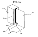
- the coating liquid is also collected at the time when the auxiliary liquid is collected, and as a result, the deposit of the liquid 107 is accumulated on the claw 104 and suction port 105 of the curtain edge guide, as shown in FIG. 4C .
- the curtain film 102 supported by the edge of the claw is sifted to the holding part because of the presence of the deposits of the liquid, and at this time, the position of the curtain film is moved away from the position of the auxiliary liquid 103, the curtain film touches the frame of the edge guide (the flow speed of the edge of the curtain film becomes slow), and inward deviation of the curtain film 102 occurs.
- the problem occurs such that the deposition amount of the edge part relative to the coating width direction becomes large. Therefore, product loss increases as the coating width is not uniformed at the time of the production.
- the deposition amount of the edge relative to the coating width direction is large, non-dry portions are generated due to inferior drying in the production.
- the coating liquid is adhered to the conveyance roll of the web 106 during the production, and thereafter the adhered coating liquid may contaminate the surface of the web coated film, or may cause blocking at the time when the final product is rolled up. Moreover, as the edge part is rose, the web may be cut or separated at the time of rolling up. Therefore, there has been a problem such that the production efficiency is lowered.
- FIG. 4A the arrow shows the conveyance direction of the web
- FIG. 4B the arrow shows the suction of the auxiliary liquid
- FIG. 4C the arrows show the suction of the air, unless otherwise indicated.
- JP-A Japanese Patent Application Laid-Open
- JP-A No. 11-188299 discloses a curtain coating method in which a porous material is used for a curtain edge guide, and auxiliary liquid is evenly poured into the contact surface between the curtain edge guide and curtain coating liquid.
- JP-A No. 2001-46939 discloses a curtain coating method in which a plate glass is arranged at the contact surface between the curtain edge guide and curtain coating liquid.
- JP-A No. 2003-71353 discloses a curtain coating method in which the pressure of a space in the upstream side in the conveyance direction of a support member intercepted by the curtain film is reduced.
- EP-A-0551237 relates to a curtain coating apparatus comprising means for continuously moving a substrate along a path through a coating zone, from an upstream direction to a downstream direction, a hopper means positioned above said path for forming a continuously flowing, liquid curtain in said coating zone, said curtain having an upstream and a downstream side and impinging on the moving web in a line transversely across the substrate to form a coated layer of said liquid thereon, an enclosure means which includes a pair of planar side walls positioned on opposite sides of the substrate parallel to the direction of movement thereof, said walls extending vertically from said hopper means to said substrate and an upstream wall extending from the hopper means to a position close to said substrate, said enclosure means, in combination with the hopper means, the substrate and the curtain, forming a pressure controlled zone in which a substantially static gas pressure can be maintained, and means for controlling the static gas pressure in said zone and for establishing a pressure differential between the upstream and downstream sides of the curtain.
- US-A-5105758 describes a catch pan for use in a curtain coating apparatus during start-up and shut-down.
- the catch pan includes flexible shims, which are in contact with edge guides and scrapes liquid in order to prevent excess liquid from depositing on the web.
- US-A-3867901 relates to an apparatus for coating the support of a photographic element by forming a free-falling vertical curtain of liquid photographic coating composition in such a manner that the free-failing curtain impinges on the support, including means for advancing a web as the support, a hopper for the coating composition provided with a lip spaced vertically above the moving support from which the coating composition flows as a free-falling curtain, and guide means defining edge guide surfaces.
- the apparatus comprises a strip attached below the edge guide for the purpose of spreading excess coating liquid on the web Further, an air shield is arranged near the web to reduce the air barrier.
- US-A-5906865 discloses a curtain coating apparatus wherein a liquid curtain falls freely between curtain holders, wherein the curtain center and the curtain edge are intercepted during freely falling.
- the curtain center falls on the web while curtain edge is vacuumed away from a vacuum aperture below a curtain holder.
- the present invention has been made in view of the above problems inherent in the related art, and an object thereof is to provide a curtain coating apparatus and curtain coating method capable of preventing unstable motion of the coating liquid curtain film caused due to influence of air surrounding the end portion of the curtain film, preventing deposition of the coating liquid on the claw of the edge guide, and preventing inward deviation of the curtain film.
- a curtain coating apparatus and curtain coating method capable of preventing unstable swing of the curtain film caused by ambient air surrounding the end portion of the coating liquid curtain film, preventing deposition of the coating liquid on the claw of the edge guide, and preventing the inward deviation of the curtain film.
- the curtain coating apparatus includes an ejection unit having a slit for ejecting coating liquid, a guide unit for guiding a coating liquid ejected from the slit in a curtain-like manner onto a support member , and a conveyance unit 6 for conveying the support member , and may further include other unit as necessary.
- the guide unit includes a curtain edge guide section provided at both edges of the coating liquid ejected in a curtain-like manner relative to the slit opening direction, and a windshield plate arranged so as to be in contact with the curtain edge guide section.
- the windshield plate is preferably (1) disposed so as to be parallel to the conveyance direction of the support member and vertical to the support member, or (2) disposed so as to be vertical to the conveyance direction of the support member and vertical to the support member.
- a length (width) of the windshield in the parallel direction to the support member is not particularly limited, and the windshield is disposed on the entire length (width) of the support member with respect to the horizontal direction.
- the length (width) of the windshield is preferably 10 mm or more, more preferably 10 mm to 30 mm.
- a length (height) of the windshield in the vertical direction to the support member is not particularly limited, and the windshield may be disposed entirely relative to the vertical direction to the support member.
- the length (height) of the windshield is preferably 10 mm or more, more preferably 10 mm to 60 mm.
- FIG. 5A is a schematic view showing a curtain coating apparatus according to a first embodiment
- FIG. 5B is a schematic view showing the curtain coating apparatus according to a first embodiment at the operation time.
- the coating liquid 3 is retained in a curtain coating head 1 which is the ejection unit having the slit.
- the coating liquid 3 is ejected from the curtain coating head 1 (allowed to freely fall) in the gravitational direction onto a web 5 which is the support member while being guided by a curtain edge guide 2 which is the curtain edge guide section provided at the both end portions of the coating liquid 3.
- the web 5 is conveyed in one direction at a constant speed by the conveyance unit including a backup roll 6 and other not-shown members.
- a vacuum unit 4 which is arranged on the upstream side in the conveyance direction of the web 5 relative to the curtain of the coating liquid 3, reduces the pressure of air in the space surrounded by the curtain edge guide 2, curtain of the coating liquid 3, web 5, and the like.
- the windshield plate 9 is arranged so as to be in contact with the curtain edge guide 2 and shields the end portion of the curtain of the coating liquid 3 from disturbed airflow.
- Reference numeral 3a denotes coating liquid (curtain film) and reference numeral 3b denotes coating liquid (on the web).
- the slit that the curtain coating head 1 has may have any shape as long as it can eject the coating liquid in a curtain-like manner.
- the slit has a rectangular cross-section with a sufficient length (in the slit opening direction) for the slit width.
- the slit width and slit length can arbitrarily be designed according to the viscosity or ejection amount of the coating liquid, the size of the web to be used, or the like.
- the curtain coating head 1 may have a plurality of slits. In this case, it is preferable that different coating liquids are ejected from the respective slits and coated onto the support member in a layered state.
- the curtain edge guide 2 may be of any kind as long as it can form the curtain film and may be a conventionally-known member.
- the coating liquid 3 may be of any kind as long as it can be formed into a curtain film and may be conventionally-known liquid.
- the vacuum unit 4 may be of any kind as long as it can suck air and reduce the pressure and may be a conventionally-known apparatus. Further, the conveyance unit including the backup roll 6 may be of any kind as long as it can convey the web 5 and may be a conventionally-known conveyance unit.
- the web 5 is a base material made of paper, film, or thin-film metal, whose surface is to be coated with coating liquid.
- the surface of the web 5 may be treated with a coating.
- FIG. 6A is a schematic perspective view of the curtain coating apparatus according to the first embodiment, showing a configuration of a portion around a curtain film end portion
- FIG. 6B is a schematic top view of the curtain coating apparatus according to the first embodiment, showing a configuration of a portion around a curtain film end portion.
- the windshield plate 9 is attached to the lower end of the curtain edge guide 2 on the opposite side in the conveyance direction of the web 5 relative to the coating liquid 3a flowing in a curtain-like manner.
- This configuration shields the end portion of the coating liquid curtain film 3a from disturbed airflow which is generated on the opposite side of the curtain edge guide 2 relative to the web conveyance direction to affect that portion, so that it is possible to prevent unstable swing of the curtain film 3a, thereby preventing inward deviation of the curtain film 3a at the curtain edge guide 2.
- the windshield plate 9 is arranged perpendicular both to the conveyance direction of the web 5 and web 5. This configuration is effective for shielding the end portion of the coating liquid curtain film 3a from disturbed airflow which is generated on the opposite side of the curtain edge guide 2 relative to the web conveyance direction to affect that portion, so that it is possible to prevent unstable swing of the curtain film 3a, thereby preventing inward deviation of the curtain film 3a at the curtain edge guide 2.
- metal such as iron, stainless steel, or aluminum and resin such as Teflon® or PET may be preferably used as a material of the windshield plate 9.
- the windshield plate 9 is preferably a plate-like member having a given width, height and thickness.
- the windshield plate 9 preferably has a length of 10 mm or more in the parallel direction (width direction of the windshield plate 9) to the web 5. This configuration is effective for shielding the end portion of the coating liquid curtain film 3a from disturbed airflow which is generated on the opposite side of the curtain edge guide 2 relative to the web conveyance direction to affect that portion, so that it is possible to prevent unstable swing of the curtain film 3a, thereby preventing inward deviation of the curtain film 3a at the curtain edge guide 2.
- the windshield plate 9 preferably has a length of 10 mm or more in the perpendicular direction (height direction of the windshield plate 9) to the web 5. This configuration is effective for shielding the end portion of the coating liquid curtain film 3a from disturbed airflow which is generated on the opposite side of the curtain edge guide 2 relative to the web conveyance direction to affect that portion, so that it is possible to prevent unstable swing of the curtain film 3a, thereby preventing inward deviation of the curtain film 3a at the curtain edge guide 2.
- the distance between the lower end (end portion at the web 5 side) of the curtain edge guide 2 and web 5 is preferably smaller than or equal to the distance between the lower end (end portion at the web 5 side) of the windshield plate 9 and web 5.
- the curtain edge guide 2 is preferably arranged closer to the web 5 than the windshield plate 9 by 0 mm to 10 mm. Namely, the distance between the curtain edge guide 2 and the web 5 is smaller than the distance between the windshield plate 9 and the web 5 by 0 mm to 10 mm.
- the curtain edge guide 2 cannot shield the end portion of the coating liquid curtain film 3a from disturbed airflow which is generated on the opposite side of the curtain edge guide 2 relative to the web conveyance direction to affect that portion, causing the curtain film 3a to swing and thereby inward deviation of the curtain film 3a at the curtain edge guide 2 occurs.
- FIG. 8 is a schematic top view of a configuration of a portion around a curtain film end portion of the windshield plate of the curtain coating apparatus according to the present invention.
- the lower end of the windshield plate 9' (end portion at the web 5 side) is inclined in a manner that a portion of the lower end is closer to the web 5 as the portion is close to the curtain edge guide 2.
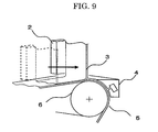
- This configuration is effective to prevent the following problem. That is, as shown in FIG. 9 , when the coating liquid curtain film 3a is moved to the web position on the backup roll 6 at production start time, if the curtain film 3a swings at this time, the coating liquid 3 is brought into contact with and caught by the windshield plate 9'. The coating liquid 3 caught by the windshield plate 9' drops to the lower end thereof. The coating liquid 3 then drops onto the web 5 to cause defective coating (blocking and the like due to excessive deposition of the coating liquid). While, the coating liquid 3 caught by the windshield plate 9' is moved to the curtain edge guide 2 side due to the inclination of the lower end of the windshield plate 9', thereby avoiding the coating liquid 3 caught by the windshield plate 9' from dropping onto the web 5.
- the inclination angle of the windshield plate 9' is preferably 0.1° to 40°.
- the curtain edge guide 2 cannot shield the end portion of the coating liquid curtain film 3a from disturbed airflow which is generated on the opposite side of the curtain edge guide relative to the web conveyance direction to affect that portion, causing the curtain film 3a to swing and thereby inward deviation of the curtain film 3a at the curtain edge guide 2 occurs.
- FIG. 7 is a schematic perspective view of a configuration of a portion around a curtain film end portion in a modification of the windshield plate of the curtain coating apparatus.
- the windshield plate 9 is arranged parallel to the conveyance direction of the web 5 and vertical to the web 5.
- This configuration shields the end portion of the coating liquid curtain film 3a from disturbed airflow which is generated on the opposite side of the curtain edge guide 2 relative to the web conveyance direction to affect that portion, so that it is possible to prevent unstable swing of the curtain film 3a, thereby preventing inward deviation of the curtain film 3a at the curtain edge guide 2.
- FIG. 10A is a schematic view showing a curtain coating apparatus according to a second embodiment
- FIG. 10B is a schematic view showing the curtain coating apparatus according to a second embodiment at the operation time.
- the guide unit has a slide surface 7 and, more preferably, a slide surface curtain edge guide section (slide portion edge guide) 8 is arranged at both end portions of the slide surface 7 relative to the slit opening direction.
- FIG. 2 The configuration shown in FIG. 2 can be applied without change to the slide surface 7 and slide surface curtain edge guide section 8.
- Configurations other than the slide surface 7 and slide surface curtain edge guide section 8 are the same as those of the curtain coating apparatus of the first embodiment, and the descriptions thereof are omitted here.
- a slide curtain coating head 1' which is an ejection unit having a slit, ejects coating liquid 3' on the slide surface 7, and the coating liquid 3' is layered on the slide surface 7.
- the ejected coating liquid 3' is slid on the slide surface 7 while being guided by the slide portion edge guide 8 which is the curtain edge guide section arranged at both end portions (slit longitudinal direction end portions in the drawings) of the layered coating liquid and then freely falls in the gravitational direction from the slide direction downstream end of the slide surface in a curtain-like manner.
- the coating liquid 3' is guided onto the web 5 which is the support member by the curtain edge guide 2 which is the curtain edge guide section arranged at both end portions of the curtain of the coating liquid 3'.
- the web 5 is conveyed in one direction at a constant speed by the conveyance unit including the backup roll 6 and other not-shown members.
- the vacuum unit 4 is arranged on the upstream side in the conveyance direction of the web 5 relative to the curtain of the coating liquid 3' and reduces the pressure of air in the space surrounded by the curtain edge guide 2, curtain of the coating liquid 3', web 5, and the like.
- the windshield plate 9 is arranged so as to be in contact with the curtain edge guide 2 and shields the end portion of the curtain of the coating liquid 3 from disturbed airflow caused at the time of conveyance of the web 5 or at the time of operation of the vacuum unit 4.
- the windshield plate 9 was attached to the lower end of the curtain edge guide 2 of the curtain coating apparatus as shown in FIG. 1 so as to be arranged parallel to the conveyance direction of the web 5 (vertical to the conveyance direction of the web) and vertical to the web 5 on the opposite side in the web conveyance direction relative to the coating liquid flowing in a curtain-like manner as shown in FIG. 6 .
- the coating liquid was coated on the web 5 (paper) at a coating speed of 400 m/min, with a coating width of 250 mm, and at a flow rate of coating liquid ejected from nozzle slit of 3,000 g/min.
- the dimension of the windshield plate 9 (PET film) was set to 30 mm width x 60 mm height x 175 ⁇ m thickness, the distance between the windshield plate 9 and web 5 was set equal to that between the curtain edge guide 2 and web 5, the vacuum pressure of the vacuum unit 4 was set to -3 kpa, and the volume of water flowing along the curtain edge guide 2 was set to 30 cc/min.
- the coating liquid had a viscosity of 300 mPa ⁇ s and a static surface tension of 35 mN/m.
- the composition of the coating liquid was as follows. (Coating liquid composition) Polyvinyl alcohol 85 parts Green pigment 5 parts Water 915 parts
- the windshield plate 9 of the Reference Example 2 was attached to the lower end of the curtain edge guide 2 so as to be arranged perpendicular (parallel to the conveyance direction of the web 5) both to the conveyance direction of the web 5 and web 5 on the opposite side in the conveyance direction of the web 5 relative to the coating liquid 3 flowing in a curtain-like manner, as shown in FIG. 7 , and the same coating procedure and evaluation as Reference Example 2 were carried out.
- the result is shown in Table 1.
Landscapes
- Coating Apparatus (AREA)
- Application Of Or Painting With Fluid Materials (AREA)
Claims (13)
- Vorhangbeschichtungsvorrichtung, umfassend:eine Ausstoßeinheit (1) mit einem Schlitz zum Ausstoßen von Beschichtungsflüssigkeit (3);eine Führungseinheit, die konfiguriert ist, um die Beschichtungsflüssigkeit (3), die von dem Schlitz ausgestoßen wird, auf ein Trägerelement (5) vorhangartig zu führen; undeine Fördereinheit (6), die konfiguriert ist, um das Trägerelement (5) zu transportieren, wobei die Führungseinheit einen Vorhangrand-Führungsabschnitt (2), der an beiden Endabschnitten der Beschichtungsflüssigkeit (3), die vorhangartig ausgestoßen wird, relativ zu einer Öffnungsrichtung des Schlitzes vorgesehen ist, und eine Windschutzplatte (9), die angeordnet ist, um in Kontakt mit dem Vorhangrand-Führungsabschnitt (2) zu sein, umfasst,dadurch gekennzeichnet, dassein unteres Ende der Windschutzplatte (9) an der Seite des Trägerelements geneigt ist, so dass ein Abschnitt des unteren Endes näher an dem Vorhangrand-Führungsabschnitt (2) näher an dem Trägerelement (5) ist, so dass beim Produktionsstartzeitpunkt, wenn Beschichtungsflüssigkeit (3) durch die Windschutzplatte (9) gefangen wird, diese Beschichtungsflüssigkeit (3) zur Seite der Vorhangrandführung (2) transportiert wird.
- Vorhangbeschichtungsvorrichtung nach Anspruch 1, wobei die Führungseinheit eine Gleitoberfläche (7) umfasst und die Ausstoßeinheit (1) die Beschichtungsflüssigkeit (3) auf die Gleitoberfläche (7) ausstößt.
- Vorhangbeschichtungsvorrichtung nach Anspruch 2, wobei die Führungseinheit einen Gleitoberflächen-Vorhangrand-Führungsabschnitt (8) an beiden Endabschnitten der Gleitoberfläche (7) relativ zu einer Öffnungsrichtung des Schlitzes aufweist.
- Vorhangbeschichtungsvorrichtung nach irgendeinem der Ansprüche 1 bis 3, wobei die Ausstoßeinheit (1) eine Mehrzahl von Schlitzen umfasst.
- Vorhangbeschichtungsvorrichtung nach irgendeinem der Ansprüche 1 bis 4, wobei die Windschutzplatte (9) auf der entgegengesetzten Seite des Vorhangrand-Führungsabschnitts (2) relativ zu einer Förderrichtung des Trägerelements (5) angeordnet ist.
- Vorhangbeschichtungsvorrichtung nach Anspruch 5, wobei die Windschutzplatte (9) parallel zu der Förderrichtung des Trägerelements (5) und senkrecht zu dem Trägerelement (5) angeordnet ist.
- Vorhangbeschichtungsvorrichtung nach Anspruch 5, wobei die Windschutzplatte (9) senkrecht sowohl zur Förderrichtung des Trägerelements (5) als auch zu dem Trägerelement (5) angeordnet ist.
- Vorhangbeschichtungsvorrichtung nach irgendeinem der Ansprüche 1 bis 7, wobei die Windschutzplatte (9) eine Länge von 10 mm oder mehr in paralleler Richtung zu dem Trägerelement (5) aufweist.
- Vorhangbeschichtungsvorrichtung nach irgendeinem der Ansprüche 1 bis 8, wobei die Windschutzplatte (9) eine Länge von 10 mm oder mehr in senkrechter Richtung zu dem Trägerelement (5) aufweist.
- Vorhangbeschichtungsvorrichtung nach irgendeinem der Ansprüche 1 bis 9, wobei der Abstand zwischen dem Vorhangrand-Führungsabschnitt (2) und dem Trägerelement (5) kleiner als der oder gleich dem Abstand zwischen der Windschutzplatte (9) und dem Trägerelement (5) ist.
- Vorhangbeschichtungsvorrichtung nach Anspruch 10, wobei der Abstand zwischen dem Vorhangrand-Führungsabschnitt (2) und dem Trägerelement (5) um 0 mm bis 10 mm kleiner als der Abstand zwischen der Windschutzplatte (9) und dem Trägerelement (5) ist.
- Vorhangbeschichtungsvorrichtung nach irgendeinem der Ansprüche 1 bis 11, wobei der Neigungswinkel des unteren Endes der Windschutzplatte (9) 0,1° bis 40° beträgt.
- Vorhangbeschichtungsverfahren, umfassend:das Ausstoßen von Beschichtungsflüssigkeit (3) aus einem Schlitz;das Führen der Beschichtungsflüssigkeit (3), die aus dem Schlitz ausgestoßen ist, auf ein Trägerelement (5) in vorhangartiger Weise mittels einer Führungseinheit; unddas Transportieren des Trägerelements (5),wobei die Führungseinheit einen Vorhangrand-Führungsabschnitt (2), der an beiden Endabschnitten der Beschichtungsflüssigkeit (3), die vorhangartig ausgestoßen wird, relativ zu einer Öffnungsrichtung des Schlitzes vorgesehen ist, und eine Windschutzplatte (9), die angeordnet ist, um in Kontakt mit dem Vorhangrand-Führungsabschnitt (2) zu sein, umfasst,dadurch gekennzeichnet, dassein unteres Ende der Windschutzplatte (9) an der Seite des Trägerelements geneigt ist, so dass ein Abschnitt des unteren Endes näher an dem Vorhangrand-Führungsabschnitt (2) näher an dem Trägerelement (5) ist, so dass beim Produktionsstartzeitpunkt, wenn Beschichtungsflüssigkeit (3) durch die Windschutzplatte (9) gefangen wird, diese Beschichtungsflüssigkeit (3) zur Seite der Vorhangrandführung (2) transportiert wird.
Applications Claiming Priority (1)
| Application Number | Priority Date | Filing Date | Title |
|---|---|---|---|
| JP2008068544 | 2008-03-17 |
Publications (2)
| Publication Number | Publication Date |
|---|---|
| EP2103357A1 EP2103357A1 (de) | 2009-09-23 |
| EP2103357B1 true EP2103357B1 (de) | 2013-02-20 |
Family
ID=40602145
Family Applications (1)
| Application Number | Title | Priority Date | Filing Date |
|---|---|---|---|
| EP20090155244 Ceased EP2103357B1 (de) | 2008-03-17 | 2009-03-16 | Vorhangbeschichtungsvorrichtung und Vorhangbeschichtungsverfahren |
Country Status (3)
| Country | Link |
|---|---|
| EP (1) | EP2103357B1 (de) |
| JP (1) | JP5439880B2 (de) |
| CN (1) | CN101537402B (de) |
Families Citing this family (6)
| Publication number | Priority date | Publication date | Assignee | Title |
|---|---|---|---|---|
| DE102009054737A1 (de) * | 2009-12-16 | 2011-06-22 | Voith Patent GmbH, 89522 | Vorhang-Auftragswerk |
| CN102337705B (zh) * | 2010-07-20 | 2013-07-31 | 中国制浆造纸研究院 | 一种用于提高帘式涂布幕帘稳定性的方法 |
| JP5938980B2 (ja) * | 2011-03-31 | 2016-06-22 | 株式会社リコー | カーテン塗布方法及びカーテン塗布装置 |
| PL2766129T3 (pl) * | 2011-10-13 | 2016-07-29 | Xylo Tech Ag | Instalacja oraz sposób powlekania kurtynowego płytowych elementów konstrukcyjnych |
| CN103657911A (zh) * | 2013-11-29 | 2014-03-26 | 陈棋伟 | 静电植绒机 |
| DE102017101373B4 (de) * | 2017-01-25 | 2022-02-03 | Voith Patent Gmbh | Vorhang-Auftragswerk und Verfahren zum Auftragen eines Auftragsmediums |
Family Cites Families (13)
| Publication number | Priority date | Publication date | Assignee | Title |
|---|---|---|---|---|
| US3632374A (en) * | 1968-06-03 | 1972-01-04 | Eastman Kodak Co | Method of making photographic elements |
| US3867901A (en) * | 1968-06-03 | 1975-02-25 | Eastman Kodak Co | Apparatus for production of photographic elements |
| EP0176632B1 (de) * | 1984-10-05 | 1988-01-07 | Agfa-Gevaert N.V. | Verfahren und Apparat zur Vorhangbeschichtung |
| US4830887A (en) * | 1988-04-22 | 1989-05-16 | Eastman Kodak Company | Curtain coating method and apparatus |
| US5105758A (en) * | 1990-08-08 | 1992-04-21 | Eastman Kodak Company | Catch pan for use in curtain coating apparatus |
| US5206057A (en) * | 1992-01-10 | 1993-04-27 | Eastman Kodak Company | Method and apparatus for adjusting the curtain impingement line in a curtain coating apparatus |
| DE19513531A1 (de) * | 1995-04-10 | 1996-10-17 | Du Pont Deutschland | Verfahren und Vorrichtung zur Verminderung von Störungen beim Vorhanggießen |
| JP3549075B2 (ja) * | 1995-06-02 | 2004-08-04 | 三菱製紙株式会社 | カーテン塗布装置及び塗布方法 |
| EP0907103B1 (de) | 1997-10-03 | 2000-08-09 | Troller Schweizer Engineering AG | Verfahren und Apparatur zur Vorhangbeschichtung eines bewegten Trägers |
| JP2000225366A (ja) * | 1999-02-03 | 2000-08-15 | Konica Corp | カーテン塗布方法及びカーテン塗布装置 |
| JP2001046939A (ja) | 1999-08-11 | 2001-02-20 | Mitsubishi Paper Mills Ltd | 塗布装置および塗布方法 |
| JP2003071353A (ja) | 2001-08-31 | 2003-03-11 | Mitsubishi Paper Mills Ltd | 塗布方法および塗布装置 |
| AU2005285221B2 (en) * | 2004-09-09 | 2010-11-11 | Avery Dennison Corporation | Curtain coating method |
-
2009
- 2009-03-16 JP JP2009063455A patent/JP5439880B2/ja active Active
- 2009-03-16 EP EP20090155244 patent/EP2103357B1/de not_active Ceased
- 2009-03-17 CN CN 200910128839 patent/CN101537402B/zh not_active Expired - Fee Related
Also Published As
| Publication number | Publication date |
|---|---|
| CN101537402B (zh) | 2013-10-30 |
| EP2103357A1 (de) | 2009-09-23 |
| JP5439880B2 (ja) | 2014-03-12 |
| JP2009255061A (ja) | 2009-11-05 |
| CN101537402A (zh) | 2009-09-23 |
Similar Documents
| Publication | Publication Date | Title |
|---|---|---|
| EP2103357B1 (de) | Vorhangbeschichtungsvorrichtung und Vorhangbeschichtungsverfahren | |
| US7101592B2 (en) | Method and apparatus for curtain coating | |
| EP0414721B1 (de) | Vorhangbeschichtungsverfahren und -vorrichtung | |
| EP1970127B1 (de) | Vorrichtung und Verfahren zur Vorhangbeschichtung | |
| JP2527665B2 (ja) | カ―テンコ―タ― | |
| JPH0691979B2 (ja) | カーテンコーテイング方法および装置 | |
| US5105758A (en) | Catch pan for use in curtain coating apparatus | |
| EP1900441B1 (de) | Vorrichtung zur Beschichtung eines Gleitvorhangs und Verfahren zur Beschichtung eines Gleitvorhangs | |
| WO1990000939A1 (en) | Curtain coating edge control method and apparatus | |
| EP0774301A1 (de) | Vorrichtung zum Entfernen einer sich auf einer sich fortbewegenden Bahn befindlichen Beschichtung und Beschichtungsvorrichtung mit einer solchen Vorrichtung | |
| TWI519354B (zh) | 滾筒搬送式塗佈機 | |
| JP3625254B2 (ja) | 塗布装置 | |
| US6610148B2 (en) | Curtain coating startup apparatus | |
| JP2005262088A (ja) | 支持体表面の防塵方法及び装置 | |
| JP2009136752A (ja) | カーテンコータのエッジガイド | |
| JPH0365266A (ja) | 塗布方法及び装置 | |
| JP2005262703A (ja) | 塗布装置及び塗布方法 | |
| JPH0578395B2 (de) | ||
| JPH02298378A (ja) | 塗装装置 | |
| JP2017094301A (ja) | 塗布装置および塗布方法 | |
| JPH0248063A (ja) | 塗装装置 | |
| KR20160144143A (ko) | 기판 처리 장치 | |
| JPH01159072A (ja) | 塗布調整装置 |
Legal Events
| Date | Code | Title | Description |
|---|---|---|---|
| PUAI | Public reference made under article 153(3) epc to a published international application that has entered the european phase |
Free format text: ORIGINAL CODE: 0009012 |
|
| AK | Designated contracting states |
Kind code of ref document: A1 Designated state(s): AT BE BG CH CY CZ DE DK EE ES FI FR GB GR HR HU IE IS IT LI LT LU LV MC MK MT NL NO PL PT RO SE SI SK TR |
|
| AX | Request for extension of the european patent |
Extension state: AL BA RS |
|
| 17P | Request for examination filed |
Effective date: 20091217 |
|
| 17Q | First examination report despatched |
Effective date: 20100127 |
|
| AKX | Designation fees paid |
Designated state(s): DE FR GB |
|
| GRAP | Despatch of communication of intention to grant a patent |
Free format text: ORIGINAL CODE: EPIDOSNIGR1 |
|
| GRAS | Grant fee paid |
Free format text: ORIGINAL CODE: EPIDOSNIGR3 |
|
| GRAA | (expected) grant |
Free format text: ORIGINAL CODE: 0009210 |
|
| AK | Designated contracting states |
Kind code of ref document: B1 Designated state(s): DE FR GB |
|
| REG | Reference to a national code |
Ref country code: GB Ref legal event code: FG4D |
|
| REG | Reference to a national code |
Ref country code: DE Ref legal event code: R096 Ref document number: 602009013384 Country of ref document: DE Effective date: 20130418 |
|
| PLBE | No opposition filed within time limit |
Free format text: ORIGINAL CODE: 0009261 |
|
| STAA | Information on the status of an ep patent application or granted ep patent |
Free format text: STATUS: NO OPPOSITION FILED WITHIN TIME LIMIT |
|
| 26N | No opposition filed |
Effective date: 20131121 |
|
| REG | Reference to a national code |
Ref country code: DE Ref legal event code: R097 Ref document number: 602009013384 Country of ref document: DE Effective date: 20131121 |
|
| REG | Reference to a national code |
Ref country code: FR Ref legal event code: PLFP Year of fee payment: 8 |
|
| REG | Reference to a national code |
Ref country code: FR Ref legal event code: PLFP Year of fee payment: 9 |
|
| REG | Reference to a national code |
Ref country code: FR Ref legal event code: PLFP Year of fee payment: 10 |
|
| PGFP | Annual fee paid to national office [announced via postgrant information from national office to epo] |
Ref country code: DE Payment date: 20180322 Year of fee payment: 10 Ref country code: GB Payment date: 20180321 Year of fee payment: 10 |
|
| PGFP | Annual fee paid to national office [announced via postgrant information from national office to epo] |
Ref country code: FR Payment date: 20180330 Year of fee payment: 10 |
|
| REG | Reference to a national code |
Ref country code: DE Ref legal event code: R119 Ref document number: 602009013384 Country of ref document: DE |
|
| GBPC | Gb: european patent ceased through non-payment of renewal fee |
Effective date: 20190316 |
|
| PG25 | Lapsed in a contracting state [announced via postgrant information from national office to epo] |
Ref country code: DE Free format text: LAPSE BECAUSE OF NON-PAYMENT OF DUE FEES Effective date: 20191001 Ref country code: GB Free format text: LAPSE BECAUSE OF NON-PAYMENT OF DUE FEES Effective date: 20190316 |
|
| PG25 | Lapsed in a contracting state [announced via postgrant information from national office to epo] |
Ref country code: FR Free format text: LAPSE BECAUSE OF NON-PAYMENT OF DUE FEES Effective date: 20190331 |