EP2101051A1 - Stockage d'énergie électrique dans un accumulateur thermique et rétro-électrification à l'aide d'un cycle thermodynamique - Google Patents
Stockage d'énergie électrique dans un accumulateur thermique et rétro-électrification à l'aide d'un cycle thermodynamique Download PDFInfo
- Publication number
- EP2101051A1 EP2101051A1 EP08004589A EP08004589A EP2101051A1 EP 2101051 A1 EP2101051 A1 EP 2101051A1 EP 08004589 A EP08004589 A EP 08004589A EP 08004589 A EP08004589 A EP 08004589A EP 2101051 A1 EP2101051 A1 EP 2101051A1
- Authority
- EP
- European Patent Office
- Prior art keywords
- heat
- steam
- turbine
- secondary side
- heat exchanger
- Prior art date
- Legal status (The legal status is an assumption and is not a legal conclusion. Google has not performed a legal analysis and makes no representation as to the accuracy of the status listed.)
- Withdrawn
Links
Images

Classifications
-
- F—MECHANICAL ENGINEERING; LIGHTING; HEATING; WEAPONS; BLASTING
- F02—COMBUSTION ENGINES; HOT-GAS OR COMBUSTION-PRODUCT ENGINE PLANTS
- F02C—GAS-TURBINE PLANTS; AIR INTAKES FOR JET-PROPULSION PLANTS; CONTROLLING FUEL SUPPLY IN AIR-BREATHING JET-PROPULSION PLANTS
- F02C1/00—Gas-turbine plants characterised by the use of hot gases or unheated pressurised gases, as the working fluid
- F02C1/04—Gas-turbine plants characterised by the use of hot gases or unheated pressurised gases, as the working fluid the working fluid being heated indirectly
- F02C1/05—Gas-turbine plants characterised by the use of hot gases or unheated pressurised gases, as the working fluid the working fluid being heated indirectly characterised by the type or source of heat, e.g. using nuclear or solar energy
-
- F—MECHANICAL ENGINEERING; LIGHTING; HEATING; WEAPONS; BLASTING
- F01—MACHINES OR ENGINES IN GENERAL; ENGINE PLANTS IN GENERAL; STEAM ENGINES
- F01D—NON-POSITIVE DISPLACEMENT MACHINES OR ENGINES, e.g. STEAM TURBINES
- F01D15/00—Adaptations of machines or engines for special use; Combinations of engines with devices driven thereby
-
- F—MECHANICAL ENGINEERING; LIGHTING; HEATING; WEAPONS; BLASTING
- F01—MACHINES OR ENGINES IN GENERAL; ENGINE PLANTS IN GENERAL; STEAM ENGINES
- F01K—STEAM ENGINE PLANTS; STEAM ACCUMULATORS; ENGINE PLANTS NOT OTHERWISE PROVIDED FOR; ENGINES USING SPECIAL WORKING FLUIDS OR CYCLES
- F01K13/00—General layout or general methods of operation of complete plants
- F01K13/006—Auxiliaries or details not otherwise provided for
-
- F—MECHANICAL ENGINEERING; LIGHTING; HEATING; WEAPONS; BLASTING
- F01—MACHINES OR ENGINES IN GENERAL; ENGINE PLANTS IN GENERAL; STEAM ENGINES
- F01K—STEAM ENGINE PLANTS; STEAM ACCUMULATORS; ENGINE PLANTS NOT OTHERWISE PROVIDED FOR; ENGINES USING SPECIAL WORKING FLUIDS OR CYCLES
- F01K23/00—Plants characterised by more than one engine delivering power external to the plant, the engines being driven by different fluids
- F01K23/02—Plants characterised by more than one engine delivering power external to the plant, the engines being driven by different fluids the engine cycles being thermally coupled
- F01K23/06—Plants characterised by more than one engine delivering power external to the plant, the engines being driven by different fluids the engine cycles being thermally coupled combustion heat from one cycle heating the fluid in another cycle
- F01K23/10—Plants characterised by more than one engine delivering power external to the plant, the engines being driven by different fluids the engine cycles being thermally coupled combustion heat from one cycle heating the fluid in another cycle with exhaust fluid of one cycle heating the fluid in another cycle
-
- F—MECHANICAL ENGINEERING; LIGHTING; HEATING; WEAPONS; BLASTING
- F01—MACHINES OR ENGINES IN GENERAL; ENGINE PLANTS IN GENERAL; STEAM ENGINES
- F01K—STEAM ENGINE PLANTS; STEAM ACCUMULATORS; ENGINE PLANTS NOT OTHERWISE PROVIDED FOR; ENGINES USING SPECIAL WORKING FLUIDS OR CYCLES
- F01K3/00—Plants characterised by the use of steam or heat accumulators, or intermediate steam heaters, therein
- F01K3/18—Plants characterised by the use of steam or heat accumulators, or intermediate steam heaters, therein having heaters
- F01K3/186—Plants characterised by the use of steam or heat accumulators, or intermediate steam heaters, therein having heaters using electric heat
-
- F—MECHANICAL ENGINEERING; LIGHTING; HEATING; WEAPONS; BLASTING
- F02—COMBUSTION ENGINES; HOT-GAS OR COMBUSTION-PRODUCT ENGINE PLANTS
- F02C—GAS-TURBINE PLANTS; AIR INTAKES FOR JET-PROPULSION PLANTS; CONTROLLING FUEL SUPPLY IN AIR-BREATHING JET-PROPULSION PLANTS
- F02C6/00—Plural gas-turbine plants; Combinations of gas-turbine plants with other apparatus; Adaptations of gas- turbine plants for special use
- F02C6/14—Gas-turbine plants having means for storing energy, e.g. for meeting peak loads
-
- F—MECHANICAL ENGINEERING; LIGHTING; HEATING; WEAPONS; BLASTING
- F05—INDEXING SCHEMES RELATING TO ENGINES OR PUMPS IN VARIOUS SUBCLASSES OF CLASSES F01-F04
- F05D—INDEXING SCHEME FOR ASPECTS RELATING TO NON-POSITIVE-DISPLACEMENT MACHINES OR ENGINES, GAS-TURBINES OR JET-PROPULSION PLANTS
- F05D2220/00—Application
- F05D2220/60—Application making use of surplus or waste energy
- F05D2220/64—Application making use of surplus or waste energy for domestic central heating or production of electricity
-
- Y—GENERAL TAGGING OF NEW TECHNOLOGICAL DEVELOPMENTS; GENERAL TAGGING OF CROSS-SECTIONAL TECHNOLOGIES SPANNING OVER SEVERAL SECTIONS OF THE IPC; TECHNICAL SUBJECTS COVERED BY FORMER USPC CROSS-REFERENCE ART COLLECTIONS [XRACs] AND DIGESTS
- Y02—TECHNOLOGIES OR APPLICATIONS FOR MITIGATION OR ADAPTATION AGAINST CLIMATE CHANGE
- Y02E—REDUCTION OF GREENHOUSE GAS [GHG] EMISSIONS, RELATED TO ENERGY GENERATION, TRANSMISSION OR DISTRIBUTION
- Y02E20/00—Combustion technologies with mitigation potential
- Y02E20/16—Combined cycle power plant [CCPP], or combined cycle gas turbine [CCGT]
Definitions
- the invention relates to a device or a method for using excess capacity in the power grid.
- controllable renewable energies can be addressed in various ways: the fluctuating supply can be compensated for by increasing or decreasing the capacity of conventional power plants, and any renewable energy that can be generated can not be fed into the grid at all. that, for example, wind turbines are switched off, or the energy could be stored in an energy storage system, ie in pumped storage power plants, compressed air storage power plants or batteries with possibly high plant complexity and high costs.
- the EP 1 577 548 A1 and the EP 1 577 549 A1 describe a device and method for storing energy and power generation. With renewable energy such as wind or solar energy generated electrical energy heats a heat storage. If necessary, the heat is used in the heat storage to generate steam that is fed directly to a thermodynamic process in a steam turbine, the steam generation is optionally complemented conventionally.
- the object of the invention is to propose an improved device and an improved method for using excess capacity in the power grid.
- a disadvantage of the prior art apparatus and method is the quality and quantity of steam produced in the heat accumulator, which is not always sufficient for operating a steam turbine, which necessitates conventional post-firing.
- the prior art apparatus and methods are limited to one medium, namely steam.
- the inventive device wants to use the excess capacity in the power grid for a number of different heat consumers and therefore provides a heat storage and a heating element for storing energy from the mains in the heat storage and a heat exchanger with a primary side and a secondary side before, the primary side for the removal of heat is thermally coupled from the heat storage to the heat storage and wherein the secondary side is connected in a power plant.
- the heat storage is thus not only used to generate steam that is fed directly to a steam turbine.
- the power plant in which the heat exchanger is connected, comprises a gas turbine, wherein the heat exchanger for air preheating is connected on the secondary side in an air supply line of a burner.
- the heat exchanger is connected on the secondary side in a fuel supply line to preheat the fuel.
- the heat exchanger is connected on the secondary side in the flow of combustion gases to their reheat.
- the heat exchanger can also be connected in a power plant, which includes a steam turbine.
- the heat exchanger is connected as a preheater on the secondary side in the water / steam cycle.
- the feedwater in the heat recovery steam generator can be replaced or supplemented by a heat exchanger, the primary side in the heat storage is switched.
- thermodynamic cycle is an existing power plant process.
- fuel is preheated with heat from the heat storage. Both preheaters reduce fuel consumption. At almost constant output power of the gas turbine preheating thus leads to an increase in the overall efficiency of the gas turbine plant.
- a high energy yield can also be achieved by reheating the exhaust gas flow in a turbine of a gas turbine.
- a steam flow of a steam turbine is reheated with the heat from the heat storage.
- FIG. 1 describes the inventive method for using overcapacities in the power grid. If, at a time t1, the generated power 1 in the network exceeds the consumption 3, the excess supply 2 of electrical energy is stored directly via a heating element in a heat storage, for example a salt storage or concrete heat storage 4.
- a heat storage for example a salt storage or concrete heat storage 4.
- the heat is removed from the heat storage again and a heat exchanger whose primary side is thermally coupled to the heat storage and the secondary side is connected to a power plant, fed to a power plant 5, so that the Power 6 generated at time t2 covers demand 7 at time t2.
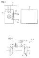
- FIG. 2 shows the essential components of the inventive device for the use of excess capacity in the power grid.
- a heating element 8 9 electrical energy can be stored directly in the heat storage 10 from the power grid.
- the primary side of the heat exchanger 11 is thermally coupled to the heat accumulator 10.
- the secondary side of the heat exchanger 11 is connected in a power plant 12.
- FIG. 3 shows a special case of FIG. 2 in which water is supplied to the heat accumulator 10 via a water line 52.
- the water is vaporized in heat exchange with the heat storage 10 and fed via the steam line 53 of the power plant 12.
- the power plant 12 shows a gas turbine 13 and includes a compressor 14 for compressing the air, which is then fed to a combustion chamber 15 and is burned with fuel.
- the hot combustion gases drive the turbine 16, which is coupled via a shaft 17 to the compressor 14.
- Heat from the heat accumulator 10 can be used via heat exchanger 11 both for preheating 18 of the compressed air, as well as for fuel preheating 19.
- the combustion chamber 15 is completely switched off and the turbine 16 is driven only by the heated air via a heat exchanger 11 compressed air.
- a reheating 20 takes place in the region of the turbine 16.
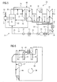
- the power plant according to FIG. 5 shows a steam power plant 21 and includes a combustion chamber 15, which are supplied via a supply system, a fuel and an oxidizing agent.
- the heat released from the combustion chamber 15 during the combustion of the fuel can be transferred to a steam generator 22.
- this is indicated by the fact that an exhaust pipe 23 is guided out of the combustion chamber 15 via a heat exchanger 24 arranged in the steam generator 22.
- any other type of suitable heat transfer from the combustion chamber 15 in the Steam generator 22, for example via a direct firing conceivable.
- the steam generator 22 is connected via a water-steam circuit 25, a steam turbine 26, which drives a generator 17, not shown, via a shaft 17.
- the steam turbine 26 is designed in three stages and comprises a high-pressure part 27, which is connected on the input side via a steam line 28 to the steam generator 22.
- the high-pressure part 27 is connected to the downstream medium-pressure part 30 of the steam turbine 26 via a superheater line 29 guided via the steam generator 22.
- the sub-turbines of the medium-pressure part 30 are in turn connected on the output side to the low-pressure parts 31 of the steam turbine 26.
- the low-pressure part 31 of the steam turbine 26 is connected downstream with a condenser 32, in which condenses the discharged from the steam turbine 26 relaxed steam.
- the capacitor 32 is in turn connected on the output side via a condensate line 33, in which a condensate pump 34 is connected to a feedwater tank 35, in which the condensed water is temporarily stored.
- a condensate pump 34 is connected to a feedwater tank 35, in which the condensed water is temporarily stored.
- This is the feedwater side via a feedwater line 36, in which a feedwater pump 37 is connected to the steam generator 22, so that the water is supplied to the boiler again and a closed water-steam circuit 25 is formed.
- a regenerative feedwater preheating in the feed water with bleed steam 54 from, for example, the low pressure part 31 of the steam turbine 26 is preheated before it is returned to the steam generator 22.
- this feedwater pre-heating is eliminated, so that the steam usually required for this purpose can be used to generate energy.
- the secondary side heat exchanger 11 are connected in the condensate line 33 and the feedwater line 36, which are connected on the primary side in the heat accumulator 10 and a coupling of the heat of the heat accumulator 10 in the water-steam cycle 25 of the steam generator 22 to ensure.
- the heat in the heat accumulator 10 can also be used to generate steam, which is then fed directly into the steam turbine 26.
- a possible feed point 48 is the leading to the high-pressure part 27 of the turbine 26 steam line 28.
- the generated steam can also be fed into the superheater line 29 49th.
- steam-heated dryers which are heated in part with high-temperature steam from the water-steam cycle of the power plant process.
- heat from the heat storage 10 can also be used for pre-drying the fuel 52.
- FIG. 6 schematically shows the steam cycle 38 of a gas and steam power plant with a heat recovery steam generator 39 and its essential components feedwater heater 40, evaporator 41 and superheater 42.
- the residual heat of the gas turbine exhaust gas is used to preheat the feedwater before it enters the boiler 43, thereby reducing the energy demand of the evaporator 41.
- the steam Via a manifold 44 in the ceiling of the boiler 43, the steam enters the superheater 42, where temperature and pressure continue to rise.
- the steam is sent to the high-pressure turbine 45, the first of a multi-stage turbine process.
- the feedwater preheater 40 may be supplemented or even replaced by either the supply of heat 46 from the heat storage 10.
- steam can also be generated directly with the heat of the heat accumulator 10 and admixed with the steam generated in the heat recovery steam generator.
Priority Applications (8)
| Application Number | Priority Date | Filing Date | Title |
|---|---|---|---|
| EP08004589A EP2101051A1 (fr) | 2008-03-12 | 2008-03-12 | Stockage d'énergie électrique dans un accumulateur thermique et rétro-électrification à l'aide d'un cycle thermodynamique |
| RU2010141759/06A RU2532635C2 (ru) | 2008-03-12 | 2009-03-05 | Аккумуляция электроэнергии тепловым аккумулятором и обратное получение электроэнергии посредством термодинамического кругового процесса |
| PCT/EP2009/052604 WO2009112421A1 (fr) | 2008-03-12 | 2009-03-05 | Stockage d'énergie électrique avec un accumulateur de chaleur et production d'énergie en retour grâce à un procédé de circuit thermodynamique |
| DK09718910.4T DK2250356T3 (da) | 2008-03-12 | 2009-03-05 | Lagring af elektrisk energi med varmeakkumulator og returomdannelse ved hjælp af en termodynamisk cyklus |
| EP09718910A EP2250356B1 (fr) | 2008-03-12 | 2009-03-05 | Stockage d'énergie électrique avec un accumulateur de chaleur et production d'énergie en retour grâce à un procédé de circuit thermodynamique |
| CN200980108788.5A CN101970832B (zh) | 2008-03-12 | 2009-03-05 | 使用热存储器的电能存储和通过热力学循环过程的回送 |
| ES09718910T ES2401849T3 (es) | 2008-03-12 | 2009-03-05 | Almacenamiento de energía eléctrica con acumulador de calor y producción de energía de retorno por medio de un proceso de circuito termodinámico |
| US12/921,415 US8938966B2 (en) | 2008-03-12 | 2009-03-05 | Storage of electrical energy with thermal storage and return through a thermodynamic cycle |
Applications Claiming Priority (1)
| Application Number | Priority Date | Filing Date | Title |
|---|---|---|---|
| EP08004589A EP2101051A1 (fr) | 2008-03-12 | 2008-03-12 | Stockage d'énergie électrique dans un accumulateur thermique et rétro-électrification à l'aide d'un cycle thermodynamique |
Publications (1)
| Publication Number | Publication Date |
|---|---|
| EP2101051A1 true EP2101051A1 (fr) | 2009-09-16 |
Family
ID=39645361
Family Applications (2)
| Application Number | Title | Priority Date | Filing Date |
|---|---|---|---|
| EP08004589A Withdrawn EP2101051A1 (fr) | 2008-03-12 | 2008-03-12 | Stockage d'énergie électrique dans un accumulateur thermique et rétro-électrification à l'aide d'un cycle thermodynamique |
| EP09718910A Active EP2250356B1 (fr) | 2008-03-12 | 2009-03-05 | Stockage d'énergie électrique avec un accumulateur de chaleur et production d'énergie en retour grâce à un procédé de circuit thermodynamique |
Family Applications After (1)
| Application Number | Title | Priority Date | Filing Date |
|---|---|---|---|
| EP09718910A Active EP2250356B1 (fr) | 2008-03-12 | 2009-03-05 | Stockage d'énergie électrique avec un accumulateur de chaleur et production d'énergie en retour grâce à un procédé de circuit thermodynamique |
Country Status (7)
| Country | Link |
|---|---|
| US (1) | US8938966B2 (fr) |
| EP (2) | EP2101051A1 (fr) |
| CN (1) | CN101970832B (fr) |
| DK (1) | DK2250356T3 (fr) |
| ES (1) | ES2401849T3 (fr) |
| RU (1) | RU2532635C2 (fr) |
| WO (1) | WO2009112421A1 (fr) |
Cited By (7)
| Publication number | Priority date | Publication date | Assignee | Title |
|---|---|---|---|---|
| WO2012047326A3 (fr) * | 2010-09-30 | 2012-10-11 | Battelle Memorial Institute | Appareil de stockage d'énergie thermique, dispositifs de commande et procédés de commande de stockage d'énergie thermique |
| DE102012204081A1 (de) * | 2012-03-15 | 2013-09-19 | Siemens Aktiengesellschaft | Energiespeicherkraftwerk |
| US8590802B2 (en) | 2009-12-17 | 2013-11-26 | Battelle Memorial Institute | Water heater control module |
| DE102013008445A1 (de) * | 2013-05-20 | 2014-11-20 | Witt Solar Ag | Wärmespeicherkraftwerk |
| EP3269948A1 (fr) * | 2016-07-15 | 2018-01-17 | Carbon-Clean Technologies GmbH | Procédé d'adaptation de la puissance d'une centrale à turbine à vapeur et centrale à turbine à vapeur |
| EP3379040A1 (fr) * | 2017-03-20 | 2018-09-26 | Lumenion GmbH | Centrale de production d'électricité et son procédé de fonctionnement |
| DE102021112050A1 (de) | 2021-05-07 | 2022-11-10 | Deutsches Zentrum für Luft- und Raumfahrt e.V. | Verfahren zum Betreiben einer Speicheranlage, Speicheranlage, Steuerungsprogramm und computerlesbares Medium |
Families Citing this family (19)
| Publication number | Priority date | Publication date | Assignee | Title |
|---|---|---|---|---|
| CN102865112B (zh) * | 2011-05-17 | 2016-02-17 | 成都奥能普科技有限公司 | 背热循环发电及多级背热循环发电及多联产系统 |
| EP2574740A1 (fr) * | 2011-09-29 | 2013-04-03 | Siemens Aktiengesellschaft | Installation de stockage d'énergie thermique |
| ES2525739B1 (es) * | 2011-11-08 | 2015-10-02 | Abengoa Solar Llc | Almacenamiento de energía térmica de alta temperatura vinculado a la red eléctrica y mejora de planta solar concentrada |
| CN103670942A (zh) * | 2012-09-07 | 2014-03-26 | 重庆大学 | 风电场汽液两相储能功率补偿系统 |
| EP2738458B2 (fr) | 2012-11-30 | 2023-05-24 | Lumenion AG | Centrale électrique et procédé de génération de courant électrique |
| DE102013004330A1 (de) | 2013-02-12 | 2014-08-14 | Carbon-Clean Technologies Gmbh | Wärmespeicher und Wärmespeicherkraftwerk |
| DE202013002455U1 (de) | 2013-02-12 | 2014-05-16 | Carbon-Clean Technologies Ag | Wärmespeicher und Wärmespeicherkraftwerk |
| DE102013210430B4 (de) * | 2013-06-05 | 2015-07-09 | Siemens Aktiengesellschaft | Energiespeichervorrichtung zur Vorwärmung von Speisewasser |
| EP2894303A1 (fr) * | 2014-01-10 | 2015-07-15 | Siemens Aktiengesellschaft | Procédé de stockage intermédiaire d'énergie électrique excédentaire |
| US10326276B2 (en) | 2015-04-06 | 2019-06-18 | Solarreserve Technology, Llc | Electrical power systems incorporating thermal energy storage |
| NL2015295B1 (nl) * | 2015-08-12 | 2017-02-28 | Johannes Maria Van Nimwegen Cornelis | Systeem voor het opslaan van elektrische energie. |
| KR102069734B1 (ko) * | 2016-02-12 | 2020-01-28 | 지멘스 악티엔게젤샤프트 | 시동 모터를 갖는 가스 터빈 트레인 |
| DE102017126959A1 (de) * | 2017-11-16 | 2019-05-16 | B+S Entwicklungsgesellschaft mbH | Heizmodul für einen fluiden Wärmeüberträger sowie Vorrichtung zur Energiespeicherung |
| CN110274218B (zh) * | 2018-03-13 | 2020-09-29 | 神华集团有限责任公司 | 从在变化的负荷条件下运行的发电站生产电力的方法和发电站 |
| CN113557617A (zh) | 2019-01-07 | 2021-10-26 | 密歇根州立大学董事会 | 热化学可再生能源储存系统和操作 |
| DE102019210737A1 (de) * | 2019-07-19 | 2021-01-21 | Siemens Aktiengesellschaft | Gasturbine mit thermischem Energiespeicher, Verfahren zum Betreiben und Verfahren zur Modifikation |
| DE102020201068A1 (de) | 2020-01-29 | 2021-07-29 | Siemens Aktiengesellschaft | Anlage mit thermischem Energiespeicher, Verfahren zum Betreiben und Verfahren zur Modifikation |
| WO2021257333A1 (fr) * | 2020-06-15 | 2021-12-23 | Bechtel Infrastructure and Power Corporation | Stockage d'énergie à air avec moteurs à combustion interne |
| DE102022000765A1 (de) | 2022-03-04 | 2023-09-07 | Alexander Lapin | Das Energiewärmespeicherkraftwerk |
Citations (7)
| Publication number | Priority date | Publication date | Assignee | Title |
|---|---|---|---|---|
| DE2757306A1 (de) * | 1977-12-22 | 1979-07-05 | Wilhelm Jakobi | Energiespeicher |
| US4262484A (en) * | 1977-10-18 | 1981-04-21 | Rolls-Royce Limited | Gas turbine engine power plant using solar energy as a heat source |
| US5384489A (en) * | 1994-02-07 | 1995-01-24 | Bellac; Alphonse H. | Wind-powered electricity generating system including wind energy storage |
| EP1577548A1 (fr) | 2004-03-16 | 2005-09-21 | Abb Research Ltd. | Dispositif et procédé de stockage d'énergie thermale et de génération d'électricité |
| EP1577549A1 (fr) | 2004-03-16 | 2005-09-21 | Abb Research Ltd. | Dispositif de stockage d'énergie thermale et de génération d'électricité |
| WO2006007733A1 (fr) * | 2004-07-23 | 2006-01-26 | New World Generation Inc. | Centrale electrique a milieu de stockage thermique |
| WO2007134466A1 (fr) * | 2006-05-24 | 2007-11-29 | Abb Research Ltd | Système de stockage d'énergie thermoélectrique et procédé pour stocker de l'énergie thermoélectrique |
Family Cites Families (17)
| Publication number | Priority date | Publication date | Assignee | Title |
|---|---|---|---|---|
| US3974642A (en) * | 1973-01-26 | 1976-08-17 | Fives-Cail Babcock Societe Anonyme | Hybrid cycle power plant with heat accumulator for storing heat exchange fluid transferring heat between cycles |
| US4229661A (en) * | 1979-02-21 | 1980-10-21 | Mead Claude F | Power plant for camping trailer |
| US4347706A (en) * | 1981-01-07 | 1982-09-07 | The United States Of America As Represented By The United States Department Of Energy | Electric power generating plant having direct coupled steam and compressed air cycles |
| SU1521284A3 (ru) * | 1985-02-02 | 1989-11-07 | Проф.Др.-Инж.Др.-Инж. Е.Х.Клаус Книциа (Фирма) | Энергетическа установка |
| DE3731627A1 (de) * | 1987-09-19 | 1989-03-30 | Klaus Prof Dr Ing Dr In Knizia | Verfahren zur leistungsregelung eines kohlekombiblocks mit integrierter kohlevergasung und nach dem verfahren betriebenes kohlekraftwerk |
| DE4103362C1 (fr) * | 1991-02-05 | 1992-04-23 | Voest Alpine Ind Anlagen | |
| US5284489A (en) * | 1992-08-19 | 1994-02-08 | United States Surgical Corporation | Filament fabricated from a blend of ionomer resin and nonionic thermoplastic resin |
| US5375410A (en) * | 1993-01-25 | 1994-12-27 | Westinghouse Electric Corp. | Combined combustion and steam turbine power plant |
| US5685155A (en) * | 1993-12-09 | 1997-11-11 | Brown; Charles V. | Method for energy conversion |
| US5634340A (en) * | 1994-10-14 | 1997-06-03 | Dresser Rand Company | Compressed gas energy storage system with cooling capability |
| US5778675A (en) * | 1997-06-20 | 1998-07-14 | Electric Power Research Institute, Inc. | Method of power generation and load management with hybrid mode of operation of a combustion turbine derivative power plant |
| DE19745272C2 (de) * | 1997-10-15 | 1999-08-12 | Siemens Ag | Gas- und Dampfturbinenanlage und Verfahren zum Betreiben einer derartigen Anlage |
| US6065280A (en) * | 1998-04-08 | 2000-05-23 | General Electric Co. | Method of heating gas turbine fuel in a combined cycle power plant using multi-component flow mixtures |
| DE10041413B4 (de) * | 1999-08-25 | 2011-05-05 | Alstom (Switzerland) Ltd. | Verfahren zum Betrieb einer Kraftwerksanlage |
| US7086231B2 (en) * | 2003-02-05 | 2006-08-08 | Active Power, Inc. | Thermal and compressed air storage system |
| US7274111B2 (en) * | 2005-12-09 | 2007-09-25 | General Electric Company | Methods and apparatus for electric power grid frequency stabilization |
| RU2325551C1 (ru) * | 2006-12-26 | 2008-05-27 | ФГОУ ВПО "Челябинский государственный агроинженерный университет" | Устройство для автономного энергоснабжения потребителей |
-
2008
- 2008-03-12 EP EP08004589A patent/EP2101051A1/fr not_active Withdrawn
-
2009
- 2009-03-05 CN CN200980108788.5A patent/CN101970832B/zh active Active
- 2009-03-05 US US12/921,415 patent/US8938966B2/en active Active
- 2009-03-05 ES ES09718910T patent/ES2401849T3/es active Active
- 2009-03-05 RU RU2010141759/06A patent/RU2532635C2/ru active
- 2009-03-05 WO PCT/EP2009/052604 patent/WO2009112421A1/fr active Application Filing
- 2009-03-05 EP EP09718910A patent/EP2250356B1/fr active Active
- 2009-03-05 DK DK09718910.4T patent/DK2250356T3/da active
Patent Citations (7)
| Publication number | Priority date | Publication date | Assignee | Title |
|---|---|---|---|---|
| US4262484A (en) * | 1977-10-18 | 1981-04-21 | Rolls-Royce Limited | Gas turbine engine power plant using solar energy as a heat source |
| DE2757306A1 (de) * | 1977-12-22 | 1979-07-05 | Wilhelm Jakobi | Energiespeicher |
| US5384489A (en) * | 1994-02-07 | 1995-01-24 | Bellac; Alphonse H. | Wind-powered electricity generating system including wind energy storage |
| EP1577548A1 (fr) | 2004-03-16 | 2005-09-21 | Abb Research Ltd. | Dispositif et procédé de stockage d'énergie thermale et de génération d'électricité |
| EP1577549A1 (fr) | 2004-03-16 | 2005-09-21 | Abb Research Ltd. | Dispositif de stockage d'énergie thermale et de génération d'électricité |
| WO2006007733A1 (fr) * | 2004-07-23 | 2006-01-26 | New World Generation Inc. | Centrale electrique a milieu de stockage thermique |
| WO2007134466A1 (fr) * | 2006-05-24 | 2007-11-29 | Abb Research Ltd | Système de stockage d'énergie thermoélectrique et procédé pour stocker de l'énergie thermoélectrique |
Cited By (19)
| Publication number | Priority date | Publication date | Assignee | Title |
|---|---|---|---|---|
| US8590802B2 (en) | 2009-12-17 | 2013-11-26 | Battelle Memorial Institute | Water heater control module |
| US9331483B2 (en) | 2009-12-17 | 2016-05-03 | Battelle Memorial Institute | Thermal energy storage apparatus, controllers and thermal energy storage control methods |
| WO2012047326A3 (fr) * | 2010-09-30 | 2012-10-11 | Battelle Memorial Institute | Appareil de stockage d'énergie thermique, dispositifs de commande et procédés de commande de stockage d'énergie thermique |
| DE102012204081A1 (de) * | 2012-03-15 | 2013-09-19 | Siemens Aktiengesellschaft | Energiespeicherkraftwerk |
| US9534508B2 (en) | 2012-03-15 | 2017-01-03 | Siemens Aktiengesellschaft | Energy storage power plant and method for operating such a power plant |
| DE102013008445A1 (de) * | 2013-05-20 | 2014-11-20 | Witt Solar Ag | Wärmespeicherkraftwerk |
| DE102013008445B4 (de) | 2013-05-20 | 2022-12-29 | Witt Solar Ag | Wärmespeicherkraftwerk |
| US10941676B2 (en) | 2016-07-15 | 2021-03-09 | Carbon-Clean Technologies Gmbh | Method for adapting the output of a steam-turbine power station, and steam-turbine power station |
| EP3269948A1 (fr) * | 2016-07-15 | 2018-01-17 | Carbon-Clean Technologies GmbH | Procédé d'adaptation de la puissance d'une centrale à turbine à vapeur et centrale à turbine à vapeur |
| WO2018010848A1 (fr) * | 2016-07-15 | 2018-01-18 | Carbon-Clean Technologies Gmbh | Procédé d'adaptation de la puissance d'une centrale à turbine à vapeur et centrale à turbine à vapeur |
| EP3379040A1 (fr) * | 2017-03-20 | 2018-09-26 | Lumenion GmbH | Centrale de production d'électricité et son procédé de fonctionnement |
| JP2020513081A (ja) * | 2017-03-20 | 2020-04-30 | ルメニオン ゲーエムベーハー | 電気エネルギーを発生させるための発電所および発電所を稼働させる方法 |
| US10858960B2 (en) | 2017-03-20 | 2020-12-08 | Lumenion Gmbh | Power plant for generating electrical energy and method for operating a power plant |
| CN110573699A (zh) * | 2017-03-20 | 2019-12-13 | 路蒙尼尔有限责任公司 | 生成电能的发电所和运行发电所的方法 |
| CN110573699B (zh) * | 2017-03-20 | 2021-10-22 | 路蒙尼尔有限责任公司 | 生成电能的发电所和运行发电所的方法 |
| WO2018172107A1 (fr) * | 2017-03-20 | 2018-09-27 | Lumenion Gmbh | Centrale électrique servant à produire une énergie électrique et procédé servant à faire fonctionner une centrale électrique |
| AU2018236959B2 (en) * | 2017-03-20 | 2023-01-05 | Lumenion Gmbh | Power plant for generating electrical energy and method for operating a power plant |
| DE102021112050A1 (de) | 2021-05-07 | 2022-11-10 | Deutsches Zentrum für Luft- und Raumfahrt e.V. | Verfahren zum Betreiben einer Speicheranlage, Speicheranlage, Steuerungsprogramm und computerlesbares Medium |
| WO2022233582A2 (fr) | 2021-05-07 | 2022-11-10 | Deutsches Zentrum für Luft- und Raumfahrt e.V. | Procédé pour faire fonctionner une installation de stockage, installation de stockage, programme de commande et support lisible par ordinateur |
Also Published As
| Publication number | Publication date |
|---|---|
| RU2010141759A (ru) | 2012-04-20 |
| US20110083443A1 (en) | 2011-04-14 |
| WO2009112421A1 (fr) | 2009-09-17 |
| DK2250356T3 (da) | 2013-05-27 |
| RU2532635C2 (ru) | 2014-11-10 |
| EP2250356A1 (fr) | 2010-11-17 |
| CN101970832B (zh) | 2014-09-03 |
| EP2250356B1 (fr) | 2013-02-27 |
| ES2401849T3 (es) | 2013-04-25 |
| CN101970832A (zh) | 2011-02-09 |
| US8938966B2 (en) | 2015-01-27 |
Similar Documents
| Publication | Publication Date | Title |
|---|---|---|
| EP2101051A1 (fr) | Stockage d'énergie électrique dans un accumulateur thermique et rétro-électrification à l'aide d'un cycle thermodynamique | |
| EP2454453B1 (fr) | Installation de centrale à vapeur dotée d'une unité de turbine à vapeur et récepteur de vapeur de traitement ainsi que procédé de fonctionnement d'une installation de centrale à vapeur dotée d'une unité de turbine à vapeur et récepteur de vapeur de traitement | |
| WO2008113482A2 (fr) | Procédé et dispositif de surchauffe intermédiaire par mise à feu lors de l'évaporation directe solaire dans une centrale thermique solaire | |
| DE10335143A1 (de) | Verfahren zur Erhöhung des Wirkungsgrades einer Gasturbinenanlage sowie dafür geeignete Gasturbinenanlage | |
| EP2447506A2 (fr) | Système destiné à la production d'énergie mécanique et/ou électrique | |
| EP2288791B1 (fr) | Utilisation d'un dispositif de turbine à gaz et à vapeur au moyen d'un convertisseur de fréquence | |
| EP2423465A2 (fr) | Procédé de fonctionnement d'une centrale à turbine à vapeur et dispositif de production de vapeur | |
| EP2100010A2 (fr) | Aube de turbine | |
| WO2008107406A2 (fr) | Installation à turbine à vapeur et procédé pour faire démarrer une installation à turbine à vapeur | |
| DE2201397A1 (de) | Verfahren und Vorrichtung zur regenerativen Vorwaermung bei Waermekraftwerken | |
| EP2811124A1 (fr) | Dispositif d'accumulation d'énergie destinée au préchauffage d'eau d'alimentation | |
| DE102012110579B4 (de) | Anlage und Verfahren zur Erzeugung von Prozessdampf | |
| DE19627425A1 (de) | Verfahren zum Betrieb einer Hybrid-Solar-Kombianlage sowie eine Hybrid-Solar-Kombianlage | |
| EP2496798A2 (fr) | Centrale électrique à combustible fossile comportant un dispositif de séparation de dioxyde de carbone et procédé pour faire fonctionner une centrale électrique à combustible fossile | |
| DE102016214447B4 (de) | Kraftwerk mit Phasenwechselmaterial-Wärmespeicher und Verfahren zum Betreiben eines Kraftwerks mit Phasenwechselmaterial-Wärmespeicher | |
| WO2015010870A2 (fr) | Procédé de fonctionnement d'une installation gaz et vapeur | |
| EP2305964A1 (fr) | Centrale à vapeur | |
| EP2138677B1 (fr) | Installation de turbines à gaz et à vapeur | |
| AT7761U1 (de) | Verfahren und einrichtung zur erzeugung von kraft und wärme | |
| DE102020131706A1 (de) | System und Verfahren zur Speicherung und Abgabe von elektrischer Energie mit deren Speicherung als Wärmeenergie | |
| EP2385223A1 (fr) | Procédé d'augmentation du degré d'efficacité d'installations de turbines à gaz et à vapeur | |
| WO2015067397A1 (fr) | Centrale thermique exploitant la chaleur perdue d'un générateur | |
| DE3042782A1 (de) | Dampfkraftanlage | |
| EP0379108A1 (fr) | Procédé de production d'énergie électrique dans un cycle combiné gaz-vapeur et installation de gazéification de combustible | |
| DE102013219166A1 (de) | Ansaugluftvorwärmsystem |
Legal Events
| Date | Code | Title | Description |
|---|---|---|---|
| PUAI | Public reference made under article 153(3) epc to a published international application that has entered the european phase |
Free format text: ORIGINAL CODE: 0009012 |
|
| AK | Designated contracting states |
Kind code of ref document: A1 Designated state(s): AT BE BG CH CY CZ DE DK EE ES FI FR GB GR HR HU IE IS IT LI LT LU LV MC MT NL NO PL PT RO SE SI SK TR |
|
| AX | Request for extension of the european patent |
Extension state: AL BA MK RS |
|
| AKX | Designation fees paid | ||
| STAA | Information on the status of an ep patent application or granted ep patent |
Free format text: STATUS: THE APPLICATION IS DEEMED TO BE WITHDRAWN |
|
| 18D | Application deemed to be withdrawn |
Effective date: 20100317 |
|
| REG | Reference to a national code |
Ref country code: DE Ref legal event code: 8566 |