EP2099658B1 - Gehäuse für eine gassackanordnung - Google Patents
Gehäuse für eine gassackanordnung Download PDFInfo
- Publication number
- EP2099658B1 EP2099658B1 EP07847508A EP07847508A EP2099658B1 EP 2099658 B1 EP2099658 B1 EP 2099658B1 EP 07847508 A EP07847508 A EP 07847508A EP 07847508 A EP07847508 A EP 07847508A EP 2099658 B1 EP2099658 B1 EP 2099658B1
- Authority
- EP
- European Patent Office
- Prior art keywords
- housing
- electrical connection
- access opening
- side wall
- passage opening
- Prior art date
- Legal status (The legal status is an assumption and is not a legal conclusion. Google has not performed a legal analysis and makes no representation as to the accuracy of the status listed.)
- Active
Links
Images


Classifications
-
- B—PERFORMING OPERATIONS; TRANSPORTING
- B60—VEHICLES IN GENERAL
- B60R—VEHICLES, VEHICLE FITTINGS, OR VEHICLE PARTS, NOT OTHERWISE PROVIDED FOR
- B60R21/00—Arrangements or fittings on vehicles for protecting or preventing injuries to occupants or pedestrians in case of accidents or other traffic risks
- B60R21/02—Occupant safety arrangements or fittings, e.g. crash pads
- B60R21/16—Inflatable occupant restraints or confinements designed to inflate upon impact or impending impact, e.g. air bags
- B60R21/20—Arrangements for storing inflatable members in their non-use or deflated condition; Arrangement or mounting of air bag modules or components
-
- B—PERFORMING OPERATIONS; TRANSPORTING
- B60—VEHICLES IN GENERAL
- B60R—VEHICLES, VEHICLE FITTINGS, OR VEHICLE PARTS, NOT OTHERWISE PROVIDED FOR
- B60R21/00—Arrangements or fittings on vehicles for protecting or preventing injuries to occupants or pedestrians in case of accidents or other traffic risks
- B60R21/01—Electrical circuits for triggering passive safety arrangements, e.g. airbags, safety belt tighteners, in case of vehicle accidents or impending vehicle accidents
- B60R21/017—Electrical circuits for triggering passive safety arrangements, e.g. airbags, safety belt tighteners, in case of vehicle accidents or impending vehicle accidents including arrangements for providing electric power to safety arrangements or their actuating means, e.g. to pyrotechnic fuses or electro-mechanic valves
Definitions
- the invention relates to a housing for an airbag arrangement of a vehicle occupant protection device.
- an airbag module for an occupant protection device with a housing for accommodating components of the protective device is known.
- an inflatable airbag and a gas generator for inflating the airbag are arranged in the housing.
- the ignition of the gas generator via a located outside the housing ignition electronics, with which the gas generator is connected via an ignition cable.
- the gas generator has an electrical connection for receiving a plug of the ignition cable.
- the housing In order to connect the ignition cable with the gas generator located in the housing, the housing has a passage opening for the ignition cable through which the ignition cable is guided into the housing interior.
- the aperture has a diameter which allows the ignition cable connector to be pulled through the passage opening. Nevertheless, the pulling through of the ignition cable through the through hole for mounting the ignition cable is cumbersome.
- Another known way to allow the installation of an ignition cable to a housing located in a gas generator is to let the gas generator with a portion in which the ignition cable is located, protrude from the housing, so that the terminal for inserting the Zündchtsteckers is accessible from the outside.
- This mounting variant has the disadvantage that in particular a by plugs connected to the gas generator ignition cable unintentionally (for example, during the installation of the airbag assembly) can be deducted from the gas generator.
- the problem to be solved by the present invention is to provide a housing for an airbag arrangement with which a secure connection of an electrical connection line to a component of the airbag arrangement can be produced in a simple manner.
- the invention makes it possible to insert an electrical connection line to be mounted simply through the formed in one of the housing parts of the housing access opening in the through hole, so that the cumbersome pulling through the electrical Connecting line through the passage opening is eliminated.
- the access opening in the side wall provides access to the passage opening from the connection edge, via which the housing parts (after inserting the electrical connection line) are to be connected to each other when closing the housing. In particular, too a prefabricated with a plug electrical connection line over the access opening are quickly and easily mounted.
- the electrical connection line is, in particular, an ignition cable which connects a gas generator provided for inflating a gas bag of the gas bag arrangement with ignition electronics.
- a further component of the airbag arrangement e.g also in addition to the ignition cable
- a device e.g a controller located outside the housing.
- the invention is not limited to a single passageway and a single access opening; Any number of these openings can be provided as required, even in both housing parts. However, only one of the housing parts preferably has a passage opening.
- passage opening is not approximately semicircular or circular segment-like adjacent to the connecting edge, but spaced therefrom and is connected via the access opening in the side wall with the connecting edge.
- passage opening is formed in a full circle.
- the access opening is formed in the form of a slot.
- the slot has a main extension direction and a narrow width in comparison with the length of the main extension direction. He can, but he must not be elongated trained.
- the slot may, for example, also have a curved or jagged course.
- the access opening between the connecting edge and the passage opening preferably runs approximately in a straight line.
- different courses of the access opening e.g. also a meandering course.
- the access opening is formed so that a moving out of an inserted into the passage opening electrical connection line is prevented from the housing part beyond the access opening therethrough or counteracts the access opening to move out.
- the access opening as mentioned z. B. at least partially curved or meandering.
- the access opening in this embodiment of the invention runs so that a tensile force on the electrical connection line in the direction of the connecting edge is at least partially counteracted by the access opening limiting portions of the side wall. This prevents the electrical connection line from being moved out of the passage opening or out of the access opening.
- many courses of the access opening are possible in principle, for. B. also a jagged course.
- the side wall is provided with a stabilizing structure in the region of the access opening (that is to say, in particular along the access opening, if it is slot-shaped or elongated).
- This stabilizing structure may, for. B. be formed by a thickening of the side wall in the region of the access opening.
- the stabilizing structure is designed such that upon insertion of an electrical connection line through the access opening or upon application of force an electrical connecting line inserted into the through opening, the side wall is hardly bent in order to ensure stable guidance of the electrical connection line in the passage opening or during insertion of the electrical connection line through the access opening.
- the stabilizing structure preferably cooperates with a strain relief to counteract bending of the sidewall by a force transmitted from the strain relief to the sidewall.
- the invention comprises an airbag module for a vehicle occupant restraint system having a housing as described above.
- a component is arranged, to which extends through the passage opening in the housing through an electrical connection line.
- the component is in particular a gas generator which serves for inflating an inflatable airbag arranged in the housing.
- the electrical connection line which extends through the passage opening in the housing to the gas generator, here is the ignition cable for igniting the gas generator.
- the housing parts of the housing are arranged so that they adjoin one another with their connecting edges, whereby a moving out of the electrical connection line from the housing part is prevented by the access opening formed in it.
- the housing is formed by the two housing parts (ie, the housing has exactly two half-shells), wherein the housing parts are connected to one another at their connection edges.
- various ways are known, such. As hooking, clipping, screwing, gluing or welding.
- a connection point eg a screw, an adhesive or welding point
- the housing parts can be connected to one another by means of a hinged hinge (eg also in one piece).
- the access opening formed in the form of a slot has a width to be measured transversely to its main extension direction, which width may be smaller or larger than the external diameter of the electrical connection line.
- a smaller diameter serves to prevent slipping into the access opening of an electrical connection line located in the passage opening or at least slipping out of the access opening.
- the width of the access opening is greater than the outer diameter of the electrical connection line, this allows a simple insertion of the connection line into the passage opening and thus a particularly simple installation.
- the slipping out of the electrical connection line from the passage opening through the access opening can be prevented in this case by other measures, in particular by the sufficiently strong connection of the two housing parts.
- the housing part with the through-passage for the electrical connection line is preferably a lower shell of a module housing (of a gas bag module), while the second (not provided with a through-opening, for example) housing part is an upper shell of the module housing.
- the upper shell covers the gas bag arrangement to the vehicle interior.
- the unfolding gas bag extends through the upper shell (more precisely, by a tear-open area arranged in the upper shell) into the vehicle interior.
- the lower shell points away from the vehicle interior in a vehicle-mounted airbag module.
- a continuous holding element is arranged above the access opening, which prevents the electrical connection line from moving out of the housing part through the access opening. This is particularly important during assembly of the electrical connection line in the housing part to prevent slipping out of the electrical connection line here.
- the holding member may be arranged to exert a pulling force on the access opening bounding portions of the side wall, so that the width of the access opening is reduced, whereby slipping out of the electrical connection line from the passage opening or through the access opening can be additionally prevented.
- the present invention allows - as mentioned above - in addition to the quick and easy installation of the electrical connection line and the arrangement of a strain relief structure, which prevents withdrawal of the electrical connection line from the housing in a direction parallel to the extension direction of the electrical connection line.
- the contour of the passage opening can be adapted to the strain relief mechanism.
- a strain relief structure covered by the invention is, in particular, an element arranged on the electrical connection line and resting against the edge of the passage opening.
- This can e.g. a thickening formed separately or integrally with, say, the sheath of the electrical connection line, e.g. in the form of a ball or a cone.
- strain relief is that it is designed as a radial recess in the electrical connection line, in which engages the edge of the passage opening.
- strain reliefs can be used together with the housing according to the invention, such. B. cable ties.
- the strain relief structure in the housing and outside of the housing, d. H. to arrange on both sides of the passage opening. This is z. B. in cable ties or clamps possible.
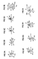
- the FIG. 1 shows a housing 1 for an airbag assembly in side view.
- the housing 1 has a first housing part designed as a lower shell 11, which is adjoined by a second housing part designed as an upper shell 12.
- the lower and the upper shell each have a side wall 111, 121, which are each closed with a connecting edge 112, 122.
- the edge of the side walls 111, 121 is formed as a connecting edge, wherein the two housing parts 11, 12 are connected to each other via the superposed connecting edges 112, 122.
- a through hole 113 is formed, through which an electrical connection line in the form of an ignition cable 2 from an outside of the housing 1 located ignition electronics (not shown) extends into the interior of the housing 1 and there with a gas generator (not shown ) connected is.
- the passage opening 113 is connected to the connection edge 112 via a access opening formed in the side wall 111 as a slot 114, so that the slot 114 in the connection edge 112 forms an access 115, through which the ignition cable 2 is inserted into the slot 114 during assembly and through the slot 114 could be inserted into the opening 113.
- the slot 114 has a bend 1141 which impedes inadvertent movement out of the ignition cable 2 located in the through-hole 113 through the slot 114 (e.g., during assembly of the housing). Moving out of the ignition cable 2 from the slot 114 through the passage 115 formed in the connecting edge 112 is additionally prevented in the assembled housing that the connecting edge 122 of the upper shell 12 in the region of the passage 115 fixed to the connecting edge 112 of the lower shell 11 connected thereto is.
- a connecting structure in the form of two clip connections 3 is provided in the region of the slot 114, which is attached to the outside of the housing 1 on both sides of the slot 114 are.
- the clip connections 3 each have a first, connected to the upper shell 12 structure 31 which partially overlaps a second, attached to the lower shell 11 structure 32 and is latched with a likewise arranged on the lower shell 11 latching structure 33.
- FIGS. 2a to 2g represent various embodiments of a slot-shaped access opening and a through hole.
- the slots 114 shown in these figures are analogous to FIG. 1 formed in a side wall 111 of a lower shell 11. It should be noted that, of course, a plurality of slots can be arranged together in a housing part or in all housing parts of the housing, even with different design. In addition, of course, all possible combinations of features in the FIGS. 2a to 2g shown slots and through holes possible.
- the slot 114 of the FIG. 2a connects a through-hole 113 to an access 115 formed in a connecting edge 112 of the side wall 111. Near the connecting edge 112, the slot 114 has a serrated structure 1142.
- the structure 1142 is intended to prevent slippage of a cable (not shown) located in the lower portion of the slot 114 or in the through-hole 113 when force is applied to the cable in a direction from the opening 113 to the connecting edge 112 to the cable ,
- the slot 114 has a curvature 1143, which is also intended to prevent a cable from slipping out of the slot 114, but at the same time makes it easier to insert a cable through the slot 114 as opposed to a serrated profile.
- the slot 114 of the Figure 2c corresponds to the slot 1114 of FIG. 2b , However, here the slot 114 does not open radially into the circular through-hole 113, but enters laterally offset into it, ie the center line of the passage opening 113 facing end portion 1145 of the slot 114 does not pass through the center 1131 of the through hole 113th
- the slot 114 has a meandering course with two curves 1143 and 1144 facing in opposite directions.
- FIGS. 2e and 2f show variants, according to which at one of the passage opening 113 facing end portion 1145 of the slot 114, a holding element 116 is arranged.
- the holding element 116 serves to prevent slippage of a cable inserted into the passage opening 113 through the slot 114 to the entrance 115 in the connection edge 112 and thus slipping out of the cable from the lower shell 11.
- the holding part can be designed and arranged above the slot such that the width d of the slot is reduced and thus additionally a cable in the passage opening 113 is secured against slipping out.
- the support member 116 spans the slot 114 and is connected at two portions 1161 and 1162 to the slot 114 at opposite side bounding portions of the side wall 111.
- different types of connections are possible, for. B. gluing, welding or screwing.
- a special variant of the attachment of the holding element 116 shows the FIG. 2f in which the holding element 116 is connected to the side wall 111 via a clip connection 1163.
- the in the Figure 2g shown side wall 111 has in the region of the passage opening 113 a stabilizing structure 1111.
- the stabilizing structure 1111 is formed in the form of a thickening of the side wall 111 extending in a star shape around the opening 113. Such a thickening may additionally be reinforced with radially extending webs with respect to the opening 113.
- such stabilizing structures are formed integrally with the side wall 111.
- FIGS. 3a to 3i show various ways to attach a strain relief in the region of the passage opening in order to secure a cable arranged in the passage opening against unintentional withdrawal (in the cable direction). Shown are each sections through the side wall 111. Through a through hole 113 in the side wall 111 each extending a cable. 2
- a cable tie 41 is arranged as a strain relief structure 4.
- the cable tie 41 is fixedly connected to the cable 2 and rests on the edge of the through hole, whereby a pulling out of the cable 2 is prevented from the housing in the direction of the cable.
- the cable 2 of the variant according to FIG. 3b has a jacket 21, which has a bead-like recess 22 in the region of the passage opening 113.
- the cable 2 in the region of the passage opening 113 has a diameter which corresponds approximately to the diameter of the passage opening 113 or is smaller, while the cable outside the passage opening has a larger diameter.
- the edge of the passage opening 113 engages in the indentation, whereby the cable 2 is fixed relative to its longitudinal direction in the passage opening 113.
- the Figures 3c and 3d show further variants of the strain relief, according to which a voltage applied to the edge of the passage opening 113 element in the form of a bead-like thickening 42 on the inside of the side wall 111 on the cable 2 is arranged.
- the thickening 42 may, for. B. applied by a resin or adhesive substance on the cable sheath or z. B. are pushed as a sleeve on the cable.
- the thickening 42 of the Figure 3c is spherical, which is the 3d figure formed in the shape of a truncated cone.
- FIG. 3e shows a side wall 111 which has in the region of the passage opening 113 on both sides (ie, the inside 1112 and the outside 1113) bead-like thickenings 1111, which act as stabilizing structures.
- Such thickening may also be formed only to one side, z. B. only to the inside 1112 ( FIG. 3f ) or only to the outside 1113 ( FIG. 3g ).
- z. B. only to the inside 1112 ( FIG. 3f ) or only to the outside 1113 ( FIG. 3g ).
- the Figures 3f and 3g can in the region of the passage opening 113 (ie in the region of the bead-like thickening 1111) additionally another strain relief mechanism z. B. be arranged in the form of a cable tie 41.
- a stabilizing structure may also be formed in the region of the passage opening 113 (and / or in the region of the slot 114) in that the side wall 111 has a particular profile, eg. B. in the form of an interior 117 of the Lower shell 11 oriented vaulting 1115 ( Fig. 3h ) which is strongest in the area of the passage opening 113 (ie, is most heavily indented at this point relative to the side wall 111).
- FIG. 3i Another variant of a curvature as a stabilizing structure shows the FIG. 3i whereafter two bulges 1116 and 1117 arranged on opposite sides of the passage opening 113 extend.
- strain reliefs 4 z. B. in the form of a thickening 42 ( FIG. 3h ) or in the form of a cable tie 41 (FIG. 3i).
Landscapes
- Engineering & Computer Science (AREA)
- Mechanical Engineering (AREA)
- Air Bags (AREA)
- Diaphragms For Electromechanical Transducers (AREA)
Description
- Die Erfindung betrifft ein Gehäuse für eine Gassackanordnung einer Fahrzeuginsassen-Schutzvorrichtung.
- Aus der
DE 197 50 945 A1 ist ein Gassackmodul für eine Insassen-Schutzvorrichtung mit einem Gehäuse zur Aufnahme von Komponenten der Schutzvorrichtung bekannt. Konkret sind in dem Gehäuse ein aufblasbarer Gassack sowie ein Gasgenerator zum Aufblasen des Gassacks angeordnet. Die Zündung des Gasgenerators erfolgt über eine außerhalb des Gehäuses befindliche Zündelektronik, mit der der Gasgenerator über ein Zündkabel verbunden ist. Der Gasgenerator weist zur Aufnahme eines Steckers des Zündkabels einen elektrischen Anschluss auf. - Um das Zündkabels mit dem im Gehäuse befindlichen Gasgenerator zu verbinden, weist das Gehäuse eine Durchgangsöffnung für das Zündkabel auf, durch die hindurch das Zündkabel in das Gehäuseinnere geführt ist. Die Öffnung hat einen Durchmesser, der es erlaubt, auch den Zündkabelstecker durch die Durchgangsöffnung hindurchzuziehen. Dennoch ist das Durchziehen des Zündkabels durch die Durchgangsöffnung zur Montage des Zündkabels umständlich.
- Eine weitere bekannte Möglichkeit, die Montage eines Zündkabels an einem in einem Gehäuse befindlichen Gasgenerator zu ermöglichen, besteht darin, den Gasgenerator mit einem Abschnitt, in dem sich der Zündkabelanschluss befindet, aus dem Gehäuse herausragen zu lassen, so dass der Anschluss zum Einstecken des Zündkabelsteckers von außen zugänglich ist. Diese Montagevariante hat den Nachteil, dass insbesondere ein per Stecker mit dem Gasgenerator verbundenes Zündkabel unbeabsichtigt (etwa bereits während der Montage der Gassackanordnung) vom Gasgenerator abgezogen werden kann.
- Darüber hinaus ist aus der gattungsgemässen
DE 202 07 400 U1 ein Gehäuseteil für ein Airbagmodul bekannt, das die Montage eines Zündkabels an einem innerhalb des Gehäuseteils angeordneten Gasgenerator erlaubt. - Das von der vorliegenden Erfindung zu lösende Problem besteht darin, ein Gehäuse für eine Gassackanordnung zu schaffen, mit dem in einfacher Weise eine sichere Verbindung einer elektrischen Verbindungsleitung mit einer Komponente der Gassackanordnung herstellbar ist.
- Dieses Problem wird durch das Gehäuse mit den Merkmalen des Anspruchs 1 gelöst. Bevorzugte und vorteilhafte Weiterbildungen der Erfindung sind in den abhängigen Ansprüchen angegeben.
- Danach wird ein Gehäuse für eine Gassackanordnung einer Fahrzeuginsassen-Schutzvorrichtung angegeben, das aufweist:
- mindestens zwei Gehäuseteile, die jeweils eine mit einer Verbindungskante abschließende Seitenwand aufweisen, wobei die Gehäuseteile bei geschlossenem Gehäuse mit den Verbindungskanten aufeinander liegen;
- eine beabstandet zur Verbindungskante in der Seitenwand eines der Gehäuseteile gebildete Durchgangsöffnung für eine mit einer Komponente der Gassackanordnung zu verbindende elektrische Verbindungsleitung; und
- eine in der Seitenwand dieser Gehäuseteil ausgebildete und von der Verbindungskante zur Durchgangsöffnung verlaufende Zugangsöffnung, durch die hindurch eine senkrecht zur Seitenwand ausgerichtete elektrische Verbindungsleitung in die Durchgangsöffnung eingelegt werden kann.
- Die Erfindung ermöglicht, eine zu montierende elektrische Verbindungsleitung einfach durch die in einem der Gehäuseteile des Gehäuses ausgebildete Zugangsöffnung in die Durchgangsöffnung einzulegen, so dass das umständliche Durchziehen der elektrischen Verbindungsleitung durch die Durchgangsöffnung entfällt. Die Zugangsöffnung in der Seitenwand schafft einen Zugang zu der Durchgangsöffnung von der Verbindungskante aus, über die die Gehäuseteile (nach Einlegen der elektrischen Verbindungsleitung) beim Schließen des Gehäuses miteinander zu verbinden sind. Insbesondere kann auch eine mit einem Stecker vorkonfektionierte elektrische Verbindungsleitung über die Zugangsöffnung schnell und einfach montiert werden.
- Dadurch, dass die fertig montierte elektrische Verbindungsleitung durch eine Durchgangsöffnung in dem Gehäuse hindurch verläuft, ist zudem eine effiziente Zugentlastung der elektrischen Verbindungsleitung realisierbar. Mit der Erfindung ist somit eine einfache Montage der elektrischen Verbindungsleitung möglich, ohne auf teine wirkungsvolle Zugentlastung verzichten zu müssen. Auf konkrete Möglichkeiten zur Herstellung einer Zugentlastung wird weiter unten eingegangen.
- Bei der elektrischen Verbindungsleitung handelt es sich insbesondere um ein Zündkabel, das einen zum Aufblasen eines Gassacks der Gassackanordnung vorgesehenen Gasgenerator mit einer Zündelektronik verbindet. Es kann jedoch auch ein sonstiges elektrisches Kabel sein, die eine weitere Komponente der Gassackanordnung (z. B. auch zusätzlich zum Zündkabel) mit einer außerhalb des Gehäuses befindlichen Einrichtung (z. B. eine Steuerung) verbindet.
- Selbstverständlich ist die Erfindung nicht auf eine einzelne Durchgangs- und eine einzelne Zugangsöffnung beschränkt; es können je nach Bedarf beliebig viele dieser Öffnungen vorgesehen sein, auch in beiden Gehäuseteilen. Bevorzugt weist jedoch nur eines der Gehäuseteile eine Durchgangsöffnung auf.
- Es wird darauf hingewiesen, dass die Durchgangsöffnung ist nicht etwa halbkreis- oder kreissegmentartig an die Verbindungskante angrenzt, sondern beabstandet zu dieser angeordnet und über die Zugangsöffnung in der Seitenwand mit der Verbindungskante verbunden ist. In einer bevorzugten Ausgestaltung der Erfindung ist Durchgangsöffnung vollkreisförmig ausgebildet.
- Weiterhin ist bevorzugt vorgesehen, dass die Zugangsöffnung in Form eines Schlitzes ausgebildet ist. Der Schlitz weist eine Haupterstreckungsrichtung und eine im Vergleich mit der Länge der Haupterstreckungsrichtung geringe Breite auf. Er kann, muss aber nicht, längserstreckt ausgebildet sein. Der Schlitz kann z.B. auch einen gekrümmten oder gezackten Verlauf haben.
- Allgemein verläuft die Zugangsöffnung zwischen der Verbindungskante und der Durchgangsöffnung bevorzugt näherungsweise geradlinig. Es können natürlich jedoch je nach konkreter Ausgestaltung des Gehäuses bzw. der Gassackanordnung verschiedene Verläufe der Zugangsöffnung (insbesondere wenn diese als Schlitz ausgebildet ist) realisiert werden, z.B. auch ein mäanderförmiger Verlauf.
- In einer besonders bevorzugten Weiterbildung der Erfindung ist die Zugangsöffnung so ausgebildet, dass ein Herausbewegen einer in die Durchgangsöffnung eingelegten elektrischen Verbindungsleitung aus dem Gehäuseteil hinaus über die Zugangsöffnung hindurch verhindert ist bzw. die Zugangsöffnung dem Herausbewegen entgegenwirkt. Hierzu kann die Zugangsöffnung wie erwähnt z. B. zumindest abschnittsweise gekrümmt oder mäanderförmig verlaufen.
- In jedem Fall verläuft die Zugangsöffnung in dieser Ausbildung der Erfindung so, dass einer Zugkraft auf die elektrische Verbindungsleitung in Richtung auf die Verbindungskante zumindest teilweise durch die Zugangsöffnung begrenzende Abschnitte der Seitenwand entgegengewirkt wird. Dadurch wird ein Herausbewegen der elektrischen Verbindungsleitung aus der Durchgangsöffnung bzw. aus der Zugangsöffnung heraus verhindert. Hierzu sind im Prinzip viele Verläufe der Zugangsöffnung möglich, z. B. auch ein zackenartiger Verlauf.
- In einer anderen vorteilhaften Weiterbildung der Erfindung ist die Seitenwand im Bereich der Zugangsöffnung (d. h. insbesondere entlang der Zugangsöffnung, wenn diese schlitzförmig oder längserstreckt ausgebildet ist) mit einer stabilisierenden Struktur versehen. Diese stabilisierende Struktur kann z. B. durch eine Verdickung der Seitenwand im Bereich der Zugangsöffnung gebildet sein. Des Weiteren ist es möglich, dass zur Stabilisierung ein Steg bzw. mehrere Stege oder eine Wulst im Bereich der Zugangsöffnung (entlang oder senkrecht zu ihr) angeordnet sind.
- Insbesondere ist die stabilisierende Struktur so ausgebildet, dass beim Einführen einer elektrischen Verbindungsleitung durch die Zugangsöffnung bzw. bei Krafteinwirkung auf eine in die Durchgangsöffnung eingelegte elektrische Verbindungsleitung die Seitenwand kaum verbogen wird, um eine stabile Führung der elektrischen Verbindungsleitung in der Durchgangsöffnung bzw. beim Einführen der elektrischen Verbindungsleitung durch die Zugangsöffnung zu gewährleisten. Die stabilisierende Struktur wirkt bevorzugt mit einer Zugentlastung zusammen, um einem Verbiegen der Seitenwand durch eine von der Zugentlastung auf die Seitenwand übertragene Kraft entgegenzuwirken.
- Des Weiteren umfasst die Erfindung ein Gassackmodul für ein Fahrzeuginsassen-Rückhaltesystem, das ein wie oben beschriebenes Gehäuse aufweist. In dem Gehäuse ist eine Komponente angeordnet, zu der sich durch die Durchgangsöffnung im Gehäuse hindurch eine elektrische Verbindungsleitung erstreckt. Bei der Komponente handelt es sich insbesondere um einen Gasgenerator, der zum Aufblasen eines im Gehäuse angeordneten aufblasbaren Gassacks dient. Die elektrische Verbindungsleitung, die sich durch die Durchgangsöffnung im Gehäuse zum Gasgenerator erstreckt, ist hier das Zündkabel zum Zünden des Gasgenerators.
- In besonders bevorzugter Weise sind die Gehäuseteile des Gehäuses so angeordnet, dass sie mit ihren Verbindungskanten aneinander grenzen, wodurch ein Herausbewegen der elektrischen Verbindungsleitung aus dem Gehäuseteil durch die in ihm ausgebildete Zugangsöffnung verhindert wird.
- Insbesondere ist das Gehäuse durch die beiden Gehäuseteile gebildet (d.h. das Gehäuse weist genau zwei Halbschalen auf), wobei die Gehäuseteile an ihren Verbindungskanten miteinander verbunden sind. Zum Verbinden der beiden Gehäuseteile sind dem Fachmann verschiedene Möglichkeiten bekannt, wie z. B. Verhaken, Verclipsen, Verschrauben, Kleben oder Schweißen. Bevorzugt befindet sich eine Verbindungsstelle (z. B. eine Schraube, ein Klebe- oder Schweißpunkt) im Bereich der Zugangsöffnung, d. h. im Bereich des Durchtritts der Zugangsöffnung durch die Verbindungskante, um in diesem Bereich eine besonders feste Verbindung der Gehäuseteile zu erzeugen und ein Herausrutschen der elektrischen Verbindungsleitung aus der Zugangsöffnung zu verhindern. Es wird auch darauf hingewiesen, dass die Gehäuseteile an einem Abschnitt mittels eines Scharniers klappbar (z.B. auch einstückig) miteinander verbunden sein können.
- In einer besonderen Weiterbildung des erfindungsgemäßen Gassackmoduls weist die in Form eines Schlitzes gebildete Zugangsöffnung eine quer zu ihrer Haupterstreckungsrichtung zu messende Breite auf, die kleiner oder größer als der Außendurchmesser der elektrischen Verbindungsleitung sein kann. Ein kleinerer Durchmesser dient dazu, ein Hineinrutschen in die Zugangsöffnung einer in der Durchgangsöffnung befindlichen elektrischen Verbindungsleitung bzw. zumindest ein Herausrutschen aus der Zugangsöffnung zu verhindern. Beim Einlegen der elektrischen Verbindungsleitung durch die Zugangsöffnung hindurch in die Durchgangsöffnung wird es durch die Zugangsöffnung "hindurchgequetscht", was z.B. durch eine entsprechend flexible Außenhülle (Isolierung) der elektrischen Verbindungsleitung ermöglicht wird.
- Ist die Breite der Zugangsöffnung größer als der Außendurchmesser der elektrischen Verbindungsleitung, so ermöglicht dies ein einfaches Einführen der Verbindungsleitung in die Durchgangsöffnung und somit eine besonders einfache Montage. Das Herausrutschen der elektrischen Verbindungsleitung aus der Durchgangsöffnung durch die Zugangsöffnung kann in diesem Fall durch andere Maßnahmen verhindert werden, insbesondere durch das ausreichend feste Verbinden der beiden Gehäuseteile.
- Das Gehäuseteil mit der Durchgangsöffnung für die elektrische Verbindungsleitung ist bevorzugt eine Unterschale eines Modulgehäuses (eines Gassackmoduls), während das zweite (z.B. nicht mit einer Durchgangsöffnung versehene) Gehäuseteil eine Oberschale des Modulgehäuses ist. Die Oberschale deckt die Gassackanordnung zum Fahrzeuginnenraum ab. Im Auslösefall erstreckt sich der sich entfaltende Gassack durch die Oberschale (genauer durch einen in der Oberschale angeordneten Aufreißbereich) in den Fahrzeug-Innenraum hinein. Die Unterschale weist in einem an einem Fahrzeug montierten Gassackmodul vom Fahrzeug-Innenraum weg.
- In einer weiteren Ausgestaltung des Moduls ist über der Zugangsöffnung ein durchgehendes Halteelement angeordnet, das ein Herausbewegen der elektrischen Verbindungsleitung aus dem Gehäuseteil durch die Zugangsöffnung hindurch verhindert. Dies ist insbesondere während der Montage der elektrischen Verbindungsleitung in dem Gehäuseteil wichtig, um hier ein Herausrutschen der elektrischen Verbindungsleitung zu verhindern. Zusätzlich kann das Haltelement so angeordnet sein, dass es auf die die Zugangsöffnung begrenzenden Abschnitte der Seitenwand eine Zugkraft ausübt, so dass sich die Breite der Zugangsöffnung verkleinert, wodurch ein Herausrutschen der elektrischen Verbindungsleitung aus der Durchgangsöffnung heraus oder durch die Zugangsöffnung hindurch zusätzlich verhindert werden kann.
- Die vorliegende Erfindung ermöglicht - wie oben bereits erwähnt - neben der schnellen und einfachen Montage der elektrischen Verbindungsleitung auch das Anordnen einer Zugentlastungsstruktur, die ein Herausziehen der elektrischen Verbindungsleitung aus dem Gehäuse in einer Richtung parallel zur Erstreckungsrichtung der elektrischen Verbindungsleitung verhindert. Hier kann zusätzlich die Kontur der Durchgangsöffnung dem Zugentlastungsmechanismus angepasst sein.
- Eine von der Erfindung erfasste Zugentlastungsstruktur ist insbesondere ein an der elektrischen Verbindungsleitung angeordnetes und am Rand der Durchgangsöffnung anliegendes Element. Diese kann z.B. eine separat oder einstückig etwa mit dem Mantel der elektrischen Verbindungsleitung ausgebildete Verdickung sein, z.B. in Form einer Kugel oder eines Kegels.
- Eine weitere Variante der Zugentlastung besteht darin, dass sie als radiale Einbuchtung in der elektrischen Verbindungsleitung ausgebildet ist, in die der Rand der Durchgangsöffnung eingreift.
- Darüber hinaus können selbstverständlich weitere, bekannte Zugentlastungen zusammen mit dem erfindungsgemäßen Gehäuses verwendet werden, wie z. B. Kabelbinder. Prinzipiell ist es möglich, die Zugentlastungsstruktur im Gehäuse als auch außerhalb des Gehäuses, d. h. beidseitig der Durchgangsöffnung anzuordnen. Dies ist z. B. bei Kabelbindern oder Klemmvorrichtungen möglich.
- Die Erfindung wird im Folgenden anhand von Ausführungsbeispielen unter Bezugnahme auf die Figuren im Einzelnen erläutert. Es zeigen:
- Fig. 1
- eine Seitenansicht einer Ausführungsvariante des erfindungsge- mäßen Gehäuses;
- Figuren 2a bis 2g
- Varianten der Zugangsöffnung;
- Figuren 3a bis 3i
- Varianten der Zugentlastung.
- Die
Figur 1 zeigt ein Gehäuse 1 für eine Gassackanordnung in Seitenansicht. Das Gehäuse 1 weist ein als Unterschale 11 ausgebildetes erstes Gehäuseteil auf, an die sich ein als Oberschale 12 ausgebildetes zweites Gehäuseteil anschließt. Die Unter- und die Oberschale weisen jeweils eine Seitenwand 111, 121 auf, die jeweils mit einer Verbindungskante 112, 122 abgeschlossen sind. Mit anderen Worten ist der Rand der Seitenwände 111, 121 als Verbindungskante gebildet, wobei die beiden Gehäuseteile 11, 12 über die aufeinander liegenden Verbindungskanten 112, 122 miteinander verbunden sind. - In der Unterschale 11 ist eine Durchgangsöffnung 113 ausgebildet, durch die hindurch sich eine elektrische Verbindungsleitung in Form eines Zündkabels 2 von einer sich außerhalb des Gehäuses 1 befindenden Zündelektronik (nicht dargestellt) ins Innere des Gehäuses 1 hinein erstreckt und dort mit einem Gasgenerator (nicht dargestellt) verbunden ist. Die Durchgangsöffnung 113 ist über eine in der Seitenwand 111 als Schlitz 114 ausgebildete Zugangsöffnung mit der Verbindungskante 112 verbunden, so dass der Schlitz 114 in der Verbindungskante 112 einen Zugang 115 ausbildet, durch den das Zündkabel 2 bei seiner Montage in den Schlitz 114 eingeführt und durch den Schlitz 114 hindurch in die Öffnung 113 eingelegt werden konnte.
- Der Schlitz 114 weist eine Krümmung 1141 auf, die ein unabsichtliches Herausbewegen des in der Durchgangsöffnung 113 befindlichen Zündkabels 2 durch den Schlitz 114 erschwert (z.B. während der Montage des Gehäuses). Ein Herausbewegen des Zündkabels 2 aus dem Schlitz 114 durch den in der Verbindungskante 112 gebildeten Durchgang 115 ist im montierten Gehäuse zusätzlich dadurch verhindert, dass die Verbindungskante 122 der Oberschale 12 im Bereich des Durchgangs 115 fest auf der Verbindungskante 112 des Unterschale 11 aufliegend mit dieser verbunden ist.
- Um die Oberschale 12 mit der Unterschale 11 insbesondere im Bereich des Schlitzes 114 bzw. des Zugangs 115 fest zu verbinden, ist im Bereich des Schlitzes 114 eine Verbindungsstruktur in Form zweier Clipverbindungen 3 vorgesehen, die beidseitig des Schlitzes 114 an der Außenseite des Gehäuses 1 angebracht sind. Die Clipverbindungen 3 weisen jeweils eine erste, mit der Oberschale 12 verbundene Struktur 31 auf, die eine zweite, an der Unterschale 11 angebrachte Struktur 32 teilweise überlappt und mit einer ebenfalls an der Unterschale 11 angeordneten Raststruktur 33 verrastet ist.
- Die
Figuren 2a bis 2g stellen verschiedene Ausführungsvarianten einer schlitzförmigen Zugangsöffnung und einer Durchgangsöffnung dar. Die in diesen Figuren gezeigten Schlitze 114 sind analog zurFigur 1 in einer Seitenwand 111 einer Unterschale 11 ausgebildet. Es wird darauf hingewiesen, dass natürlich auch mehrere Schlitze gemeinsam in einem Gehäuseteil oder in sämtlichen Gehäuseteilen des Gehäuses angeordnet sein können, auch mit unterschiedlicher Ausgestaltung. Zudem sind selbstverständlich auch alle möglichen Kombinationen von Merkmalen der in denFiguren 2a bis 2g dargestellten Schlitze und Durchgangsöffnungen möglich. - Der Schlitz 114 der
Figur 2a verbindet eine Durchgangsöffnung 113 mit einem in einer Verbindungskante 112 der Seitenwand 111 ausgebildeten Zugang 115. In der Nähe der Verbindungskante 112 weist der Schlitz 114 eine zackenartige Struktur 1142 auf. Die Struktur 1142 soll ein Herausrutschen eines im unteren Teil des Schlitzes 114 bzw. in der Durchgangsöffnung 113 befindlichen Kabels (nicht dargestellt) verhindern, wenn auf das Kabel eine Kraft in einer Richtung von der Öffnung 113 auf die Verbindungskante 112 zu auf das Kabel ausgeübt wird. - In der
Figur 2b weist der Schlitz 114 anstelle eines Zackens eine Krümmung 1143 auf, die ebenfalls ein Herausrutschen eines Kabels aus dem Schlitz 114 verhindern soll, gleichzeitig aber ein gegenüber einem zackenförmigen Verlauf einfacheres Einführen eines Kabels durch den Schlitz 114 ermöglicht. - Der Schlitz 114 der
Figur 2c entspricht dem Schlitz 1114 derFigur 2b . Allerdings mündet hier der Schlitz 114 nicht radial in die kreisförmig ausgebildete Durchgangsöffnung 113, sondern tritt seitlich versetzt in sie ein, d. h. die Mittellinie des der Durchgangsöffnung 113 zugewandten Endabschnitts 1145 des Schlitzes 114 verläuft nicht durch den Mittelpunkt 1131 der Durchgangsöffnung 113. - Im Ausführungsbeispiel der
Figur 2d weist der Schlitz 114 einen mäanderförmigen Verlauf mit zwei in entgegengesetzte Richtungen weisenden Krümmungen 1143 und 1144 auf. - Die
Figuren 2e und 2f zeigen Varianten, wonach an einem der Durchgangsöffnung 113 zugewandten Endabschnitt 1145 des Schlitzes 114 ein Halteelement 116 angeordnet ist. Das Halteelement 116 dient dazu, ein Herausrutschen eines in die Durchgangsöffnung 113 eingelegten Kabels durch den Schlitz 114 zum Zugang 115 in der Verbindungskante 112 und damit ein Herausrutschen des Kabels aus der Unterschale 11 zu verhindern. Gleichzeitig kann das Halteteil so ausgebildet und über dem Schlitz angeordnet sein, dass sich die Breite d des Schlitzes verkleinert und somit zusätzlich ein Kabel in der Durchgangsöffnung 113 gegen Herausrutschen gesichert wird. - Das Halteelement 116 überspannt den Schlitz 114 und ist an zwei Abschnitten 1161 und 1162 mit den Schlitz 114 an gegenüberliegende Seiten begrenzenden Abschnitten der Seitenwand 111 verbunden. Zum Verbinden des Halteelements 116 mit der Seitenwand 111 sind unterschiedliche Arten von Verbindungen möglich, z. B. Verkleben, Verschweißen oder Verschrauben. Eine spezielle Variante der Befestigung des Halteelements 116 zeigt die
Figur 2f , wonach das Halteelement 116 über eine Clipverbindung 1163 mit der Seitenwand 111 verbunden ist. - Die in der
Figur 2g dargestellte Seitenwand 111 weist im Bereich der Durchgangsöffnung 113 eine stabilisierende Struktur 1111 auf. Die stabilisierende Struktur 1111 ist in Form einer sich sternförmig um die Öffnung 113 herum erstreckenden Verdickung der Seitenwand 111 ausgebildet. Eine derartige Verdickung kann zusätzlich mit sich in Bezug auf die Öffnung 113 radial erstreckenden Stegen verstärkt sein. Insbesondere sind derartige stabilisierende Strukturen einstückig mit der Seitenwand 111 ausgebildet. - Die
Figuren 3a bis 3i zeigen verschiedene Möglichkeiten, eine Zugentlastung im Bereich der Durchgangsöffnung anzubringen, um ein in der Durchgangsöffnung angeordnetes Kabel gegen ein unabsichtliches Herausziehen (in Kabelrichtung) zu sichern. Dargestellt sind jeweils Schnitte durch die Seitenwand 111. Durch eine Durchgangsöffnung 113 in der Seitenwand 111 erstreckt sich jeweils ein Kabel 2. - In der Variante der
Figur 3a ist im Innern 117 des Gehäuses 11 ein Kabelbinder 41 als Zugentlastungsstruktur 4 angeordnet. Der Kabelbinder 41 ist fest mit dem Kabel 2 verbunden und liegt am Rand der Durchgangsöffnung auf, wodurch ein Herausziehen des Kabels 2 aus dem Gehäuse in Richtung des Kabels verhindert wird. - Das Kabel 2 der Variante gemäß
Figur 3b weist einen Mantel 21 auf, der im Bereich der Durchgangsöffnung 113 eine sickenartige Einbuchtung 22 besitzt. Durch die Einbuchtung 22 weist das Kabel 2 im Bereich der Durchgangsöffnung 113 einen Durchmesser auf, der näherungsweise dem Durchmesser der Durchgangsöffnung 113 entspricht bzw. kleiner ist, während das Kabel außerhalb der Durchgangsöffnung einen größeren Durchmesser aufweist. Der Rand der Durchgangsöffnung 113 greift in die Einbuchtung ein, wodurch das Kabel 2 bezogen auf seine Längsrichtung in der Durchgangsöffnung 113 fixiert wird. - Die
Figuren 3c und 3d zeigen weitere Varianten der Zugentlastung, wonach ein am Rand der Durchgangsöffnung 113 anliegendes Element in Form einer wulstartigen Verdickung 42 an der Innenseite der Seitenwand 111 an dem Kabel 2 angeordnet ist. Die Verdickung 42 kann z. B. durch eine harz- oder klebstoffartige Substanz auf den Kabelmantel aufgetragen oder z. B. als Hülse auf das Kabel aufgeschoben werden. Die Verdickung 42 derFigur 3c ist kugelförmig, die derFigur 3d in Form eines Kegelstumpfes ausgebildet. - Die Variante der
Figur 3e zeigt eine Seitenwand 111, die im Bereich der Durchgangsöffnung 113 zu beiden Seiten (d. h. zur Innenseite 1112 und zur Außenseite 1113) wulstartige Verdickungen 1111 aufweist, die als stabilisierende Strukturen wirken. Derartige Verdickungen können auch nur zu einer Seite hin ausgebildet sein, z. B. nur zur Innenseite 1112 (Figur 3f ) oder nur zur Außenseite 1113 (Figur 3g ). Gemäß denFiguren 3f und 3g kann im Bereich der Durchgangsöffnung 113 (d. h. im Bereich der wulstartigen Verdickung 1111) zusätzlich ein weiterer Zugentlastungsmechanismus z. B. in Form eines Kabelbinders 41 angeordnet sein. - Eine stabilisierende Struktur kann im Bereich der Durchgangsöffnung 113 (und/oder auch im Bereich des Schlitzes 114) auch dadurch gebildet sein, dass die Seitenwand 111 einen besonderen Verlauf aufweist, z. B. in Form einer sich zum Innern 117 der Unterschale 11 orientierenden Wölbung 1115 (
Fig. 3h ), die im Bereich der Durchgangsöffnung 113 am stärksten ist (d. h. an dieser Stelle bezogen auf die Seitenwand 111 am stärksten eingebuchtet ist). - Eine andere Variante einer Wölbung als stabilisierende Struktur zeigt die
Figur 3i , wonach sich zwei, an gegenüberliegenden Seiten der Durchgangsöffnung 113 angeordnete Wölbungen 1116 und 1117 erstrecken. Zusätzlich können zu den in denFiguren 3h und 3i gezeigten stabilisierenden Strukturen in Form von Wölbungen Zugentlastungen 4, z. B. in Form einer Verdickung 42 (Figur 3h ) oder in Form eines Kabelbinders 41 (Figur 3i) vorgesehen sein. - Die in den
Figuren 2 und3 gezeigten Varianten der Durchgangsöffnung, des Schlitzes und der Zugentlastung können selbstverständlich auch in Kombinationen realisiert sein, die in den Figuren nicht dargestellt sind. Insbesondere können die Zugentlastungsmechanismen und Stabilisierungsstrukturen derFigur 3 mit den inFigur 2 dargestellten Varianten des Schlitzes und der Durchgangsöffnung kombiniert werden. -
- 1
- Gehäuse
- 11
- Unterschale
- 12
- Oberschale
- 111, 121
- Seitenwand
- 1111, 1112
- Verdickung
- 1113
- Außenseite
- 1115, 1116, 1117
- Wölbung
- 112, 122
- Verbindungskante
- 113
- Durchgangsöffnung
- 1131
- Mittelpunkt
- 114
- Schlitz
- 1141, 1143, 1144
- Krümmung
- 1142
- Zacken
- 115
- Zugang
- 116
- Halteelement
- 117
- Gehäuseinneres
- 1161,1162
- Abschnitt
- 1163
- Clipstruktur
- 2
- Kabel
- 22
- Verjüngung
- 3
- Clipverbindung
- 31
- erste Struktur
- 32
- zweite Struktur
- 33
- Raststruktur
- 4
- Zugentlastung
- 41
- Kabelbinder
- 42
- Wulst
Claims (15)
- Gehäuse für eine Gassackanordnung einer Fahrzeuginsassen-Schutzvorrichtung, mit- mindestens zwei Gehäuseteilen (11, 12), die jeweils eine mit mindestens einer Verbindungskante (112, 122) abschließende Seitenwand (111, 121) aufweisen, wobei die Gehäuseteile (11, 12) bei geschlossenem Gehäuse über Verbindungskanten (112, 122) aneinander liegen; und- einer Durchgangsöffnung (113) für eine mit einer Komponente der Gassackanordnung zu verbindende elektrische Verbindungsleitung (2), die beabstandet zu der oder jeder Verbindungskante (112, 122) in der Seitenwand (111) eines der Gehäuseteile (11, 12) gebildet ist,gekennzeichnet durch
eine in der Seitenwand (111) dieses Gehäuseteils (11) ausgebildeten und von der Verbindungskante (112) zur Durchgangsöffnung (113) verlaufenden Zugangsöffnung (114), durch die hindurch eine winklig zur Seitenwand (111) ausgerichtete elektrische Verbindungsleitung (2) in die Durchgangsöffnung (113) eingeführt werden kann. - Gehäuse nach Anspruch 1, dadurch gekennzeichnet, dass nur eines der Gehäuseteile (11, 12) eine Durchgangsöffnung (113) aufweist.
- Gehäuse nach einem der vorhergehenden Ansprüche, dadurch gekennzeichnet, dass die Durchgangsöffnung (113) näherungsweise vollkreisförmig ausgebildet ist.
- Gehäuse nach einem der vorhergehenden Ansprüche, dadurch gekennzeichnet, dass die Zugangsöffnung (114) in Form eines Schlitzes ausgebildet ist.
- Gehäuse nach einem der vorhergehenden Ansprüche, dadurch gekennzeichnet, dass die Zugangsöffnung (114) so ausgebildet ist, dass sie einem Herausbewegen einer in die Durchgangsöffnung (113) eingelegten elektrischen Verbindungsleitung (2) aus der Gehäuseteil (11) durch die Zugangsöffnung (114) hindurch zur Verbindungskante (112) entgegenwirkt.
- Gehäuse nach einem der vorhergehenden Ansprüche, dadurch gekennzeichnet, dass die Seitenwand (111) im Bereich der Zugangsöffnung (114) und/oder der Durchgangsöffnung (113) eine stabilisierende Struktur (1111, 1112) aufweist.
- Gehäuse nach Anspruch 6, dadurch gekennzeichnet, dass die stabilisierende Struktur (1111, 1112) durch eine Verdickung der Seitenwand (111) gebildet ist.
- Gehäuse nach Anspruch 6 oder 7, dadurch gekennzeichnet, dass die stabilisierende Struktur (1111, 1112) einen an der Seitenwand (111) angeordneten Steg oder eine Wulst aufweist.
- Gassackmodul für ein Fahrzeuginsassen-Rückhaltesystem, mit- einem Gehäuse (1) gemäß einem der vorhergehenden Ansprüche;- einer in dem Gehäuse (1) angeordneten Komponente;- einer elektrischen Verbindungsleitung (2), die sich durch die Durchgangsöffnung (113) im Gehäuse (1) hindurch zu der Komponente erstreckt.
- Gassackmodul nach Anspruch 9, dadurch gekennzeichnet, dass die Gehäuseteile (11, 12) des Gehäuses (1) mit ihren Verbindungskanten (112, 122) aufeinander liegen, so dass ein Herausbewegen der elektrischen Verbindungsleitung (2) aus dem einen Gehäuseteil (11) durch die in ihm ausgebildete Zugangsöffnung (114) hindurch zur Verbindungskante (112) verhindert ist.
- Gassackmodul nach Anspruch 9 oder 10, dadurch gekennzeichnet, dass in dem Gehäuse (1) ein aufblasbarer Gassack angeordnet und die Komponente ein Gasgenerator zum Aufblasen des Gassacks ist.
- Gassackmodul nach einem der Ansprüche 9 bis 11, dadurch gekennzeichnet, dass die Zugangsöffnung (114) schlitzartig ausgebildet ist und quer zu ihrer Haupterstreckungsrichtung eine Breite (d) aufweist, die kleiner ist als der Außendurchmesser der elektrischen Verbindungsleitung (2) oder die dem Außendurchmesser der elektrischen Verbindungsleitung (2) entspricht.
- Gassackmodul nach einem der Ansprüche 9 bis 12, dadurch gekennzeichnet, dass die Zugangsöffnung (114) schlitzartig ausgebildet ist und quer zu ihrer Haupterstreckungsrichtung eine Breite (d) aufweist, die größer ist als der Außendurchmesser der elektrischen Verbindungsleitung (2).
- Gassackmodul nach einem der Ansprüche 9 bis 13, dadurch gekennzeichnet, dass sich über die Zugangsöffnung (114) ein durchgehendes Haltelement (116) erstreckt, das ein Herausbewegen der elektrischen Verbindungsleitung (2) aus dem Gehäuseteil (11) durch die Zugangsöffnung (114) hindurch zur Verbindungskante (112) verhindert.
- Gassackmodul nach einem der Ansprüche 9 bis 14, gekennzeichnet durch eine mit der elektrischen Verbindungsleitung (2) zusammenwirkende Zugentlastungsstruktur (4), die einem Herausziehen der elektrische Verbindungsleitung (2) aus dem Gehäuse (1) in einer Richtung parallel zur Erstreckungsrichtung der elektrischen Verbindungsleitung (2) entgegenwirkt.
Applications Claiming Priority (2)
| Application Number | Priority Date | Filing Date | Title |
|---|---|---|---|
| DE202006018701U DE202006018701U1 (de) | 2006-12-05 | 2006-12-05 | Gehäuse für eine Gassackanordnung |
| PCT/EP2007/062992 WO2008068188A1 (de) | 2006-12-05 | 2007-11-29 | Gehäuse für eine gassackanordnung |
Publications (2)
| Publication Number | Publication Date |
|---|---|
| EP2099658A1 EP2099658A1 (de) | 2009-09-16 |
| EP2099658B1 true EP2099658B1 (de) | 2010-10-27 |
Family
ID=37853285
Family Applications (1)
| Application Number | Title | Priority Date | Filing Date |
|---|---|---|---|
| EP07847508A Active EP2099658B1 (de) | 2006-12-05 | 2007-11-29 | Gehäuse für eine gassackanordnung |
Country Status (8)
| Country | Link |
|---|---|
| US (1) | US7832758B2 (de) |
| EP (1) | EP2099658B1 (de) |
| JP (1) | JP5061197B2 (de) |
| CN (1) | CN101522479B (de) |
| AT (1) | ATE485975T1 (de) |
| DE (2) | DE202006018701U1 (de) |
| RU (1) | RU2441780C2 (de) |
| WO (1) | WO2008068188A1 (de) |
Families Citing this family (1)
| Publication number | Priority date | Publication date | Assignee | Title |
|---|---|---|---|---|
| JP4323571B2 (ja) | 1997-01-31 | 2009-09-02 | エックスワイ, インコーポレイテッド | 光学装置 |
Family Cites Families (32)
| Publication number | Priority date | Publication date | Assignee | Title |
|---|---|---|---|---|
| US270028A (en) * | 1883-01-02 | Self-belting pulley | ||
| US3723684A (en) * | 1971-04-09 | 1973-03-27 | Itt | Pressure responsive switch with parallel contact blades bent apart by axial force applied by diaphragm |
| SE7506371L (sv) | 1974-06-11 | 1975-12-12 | William George Bradley | Anordning vid metspo. |
| DD115256A1 (de) | 1974-09-20 | 1975-09-12 | ||
| DE8802687U1 (de) | 1988-03-01 | 1988-05-05 | Kock, Rainer, Dipl.-Volksw., 3000 Hannover | Verschluß für ein Arm-, Schmuck- oder sonstiges Band |
| DE3906175C2 (de) | 1988-03-01 | 1993-12-09 | Kock Rainer Dipl Volksw | Verschluß für ein Arm- oder Schmuckband, einen Gürtel, einen Gurt oder dergleichen |
| DE9004686U1 (de) | 1990-04-26 | 1990-07-05 | Standard Elektrik Lorenz Ag, 7000 Stuttgart | Gehäuse mit Kabeldurchführung |
| US5058919A (en) | 1990-06-15 | 1991-10-22 | Trw Vehicle Safety Systems, Inc | Air bag module construction and assembly technique |
| US5296659A (en) * | 1993-01-19 | 1994-03-22 | Viz Manufacturing Company, Inc. | Differential pressure monitoring device |
| US5533750A (en) * | 1995-06-01 | 1996-07-09 | Takata, Inc. | Simplified inflatable restraint module |
| US5645298A (en) * | 1996-01-05 | 1997-07-08 | Trw Inc./Trw Vehicle Safety Systems, Inc. | Inflator for an inflatable vehicle occupant protection device |
| US5700028A (en) * | 1996-03-19 | 1997-12-23 | General Motors Corporation | Air bag module with energy absorbing mounting bracket |
| US5683105A (en) * | 1996-07-12 | 1997-11-04 | Morton International, Inc. | Electromechanical automotive air bag inflator |
| WO1998015432A1 (de) * | 1996-10-10 | 1998-04-16 | Volkswagen Aktiengesellschaft | Airbag-einrichtung für ein kraftfahrzeug |
| US5855392A (en) * | 1996-10-30 | 1999-01-05 | General Motors Corporation | Air bag cover and membrane horn switch assembly |
| US5876060A (en) * | 1996-12-05 | 1999-03-02 | Takata, Inc. | Seat mounted side impact module |
| US5876062A (en) * | 1997-07-29 | 1999-03-02 | Autoliv Asp, Inc. | Airbag inflator with direct electrical ignition for small sized gas generant bodies |
| US6131946A (en) * | 1998-06-30 | 2000-10-17 | Toyoda Gosei Co., Ltd. | Steering wheel |
| DE29900087U1 (de) | 1999-01-05 | 1999-04-08 | Delphi Technologies, Inc., Troy, Mich. | Kabeldurchführung |
| DE19915159A1 (de) | 1999-04-01 | 2000-10-05 | Klaus Gehrmann | Verschlußvorrichtung für elektrische Stecker, oder dergleichen |
| DE10059992A1 (de) | 2000-12-02 | 2002-06-06 | Daimler Chrysler Ag | Kabelführung |
| DE20116012U1 (de) | 2001-09-28 | 2001-11-29 | Bendler Elektro GmbH, 59755 Arnsberg | Installationseinrichtung |
| DE20207400U1 (de) * | 2002-05-06 | 2002-08-29 | TAKATA-PETRI (Ulm) GmbH, 89081 Ulm | Gehäuseteil für ein Airbagmodul |
| GB2396336B (en) * | 2002-12-19 | 2005-12-28 | * Autoliv Development Ab | Improvements in or relating to housings for air-bag units |
| ES2278298T3 (es) | 2003-02-20 | 2007-08-01 | Murrplastik Systemtechnik Gmbh | Paramuros para cables. |
| US6942247B2 (en) * | 2003-03-12 | 2005-09-13 | Delphi Technologies, Inc. | Driver airbag formed contact spring |
| DE102004006319B4 (de) | 2004-02-10 | 2010-06-02 | Autoliv Development Ab | Gassack-Einheit |
| DE102005031108A1 (de) | 2004-07-09 | 2006-01-26 | Trw Automotive Gmbh | Gassackmodul |
| US7621560B2 (en) * | 2005-02-07 | 2009-11-24 | Key Safety Systems, Inc | Horn switch |
| EP1707469A1 (de) * | 2005-04-01 | 2006-10-04 | Key Safety Systems, Inc. | Lenkrad mit feststehendem nabemontiertem Teil |
| DE202005020718U1 (de) | 2005-04-09 | 2006-06-22 | Adc Gmbh | Vorrichtung zur EMV-dichten Kabeldurchführung |
| DE202005019375U1 (de) | 2005-12-05 | 2006-02-16 | Takata-Petri (Ulm) Gmbh | Airbagmodul für ein Kraftfahrzeug |
-
2006
- 2006-12-05 DE DE202006018701U patent/DE202006018701U1/de not_active Expired - Lifetime
-
2007
- 2007-11-29 EP EP07847508A patent/EP2099658B1/de active Active
- 2007-11-29 DE DE502007005498T patent/DE502007005498D1/de active Active
- 2007-11-29 RU RU2009118550/11A patent/RU2441780C2/ru not_active IP Right Cessation
- 2007-11-29 AT AT07847508T patent/ATE485975T1/de active
- 2007-11-29 CN CN2007800382625A patent/CN101522479B/zh not_active Expired - Fee Related
- 2007-11-29 JP JP2009539708A patent/JP5061197B2/ja not_active Expired - Fee Related
- 2007-11-29 WO PCT/EP2007/062992 patent/WO2008068188A1/de not_active Ceased
-
2009
- 2009-05-06 US US12/453,289 patent/US7832758B2/en not_active Expired - Fee Related
Also Published As
| Publication number | Publication date |
|---|---|
| ATE485975T1 (de) | 2010-11-15 |
| RU2009118550A (ru) | 2011-01-20 |
| CN101522479A (zh) | 2009-09-02 |
| US20090224517A1 (en) | 2009-09-10 |
| US7832758B2 (en) | 2010-11-16 |
| JP2010511558A (ja) | 2010-04-15 |
| CN101522479B (zh) | 2011-07-13 |
| DE202006018701U1 (de) | 2007-03-01 |
| DE502007005498D1 (de) | 2010-12-09 |
| JP5061197B2 (ja) | 2012-10-31 |
| RU2441780C2 (ru) | 2012-02-10 |
| EP2099658A1 (de) | 2009-09-16 |
| WO2008068188A1 (de) | 2008-06-12 |
Similar Documents
| Publication | Publication Date | Title |
|---|---|---|
| EP2287047B1 (de) | Gassackmodul | |
| DE102009031120B4 (de) | Airbageinrichtung für ein Kraftfahrzeug | |
| DE10253227A1 (de) | Lüfter, insbesondere Gerätelüfter | |
| DE102005026471B4 (de) | Halter für eine Leitung in einem Automobil | |
| WO2014106567A1 (de) | Gassackeinheit | |
| DE102007042944A1 (de) | Steckverbinder mit einem einteiligen Isolierkörper | |
| EP1911632A1 (de) | Befestigungsvorrichtung für eine Leitung | |
| DE202010003385U1 (de) | Elektrische Anschlussklemme | |
| WO2018077714A1 (de) | Gassackmodul | |
| DE102010002634B4 (de) | Befestigungsanordnung für Kabelführungen | |
| WO2008068188A1 (de) | Gehäuse für eine gassackanordnung | |
| EP1985502B1 (de) | Kabelführung in einer Antriebseinheit eines deichselgelenkten Flurförderzeugs | |
| EP1402600A1 (de) | Elektrische steckverbindung | |
| DE102016120177A1 (de) | Gassackmodul | |
| DE102004033295A1 (de) | Gassack-Modul | |
| EP3772778B1 (de) | Trägersystem zur befestigung eines länglichen gegenstands sowie spangenaufsatz | |
| DE102015120002B4 (de) | Verbindungsvorrichtung und Verbindungsverfahren | |
| EP2642625B1 (de) | Mehrzweck-Kabelhalter | |
| DE102020104986A1 (de) | Gassackmodul, Verfahren zum Austausch eines Gasgenerators eines Gassackmoduls sowie Verfahren zur Herstellung eines Gassackmoduls | |
| EP3859920B1 (de) | Abstandhalter | |
| DE19638305C2 (de) | Vorrichtung zum Befestigen von in einem Hohlraum verlaufenden flexiblen Leitungen, Kabeln oder Schläuchen an einem Wandungsteil des Hohlraums sowie eine Anordnung zum definierten Verlegen dieser Leitungen, Kabel oder Schläuche in diesem Hohlraum | |
| EP3183159B1 (de) | Lenksäule für ein kraftfahrzeug | |
| DE10116165B4 (de) | Vorrichtung zur Herstellung von abgehängten Decken | |
| EP2333905A1 (de) | Batterieklemme mit Innenschelle und Außenschelle | |
| EP3631213B1 (de) | Befestigungssystem |
Legal Events
| Date | Code | Title | Description |
|---|---|---|---|
| PUAI | Public reference made under article 153(3) epc to a published international application that has entered the european phase |
Free format text: ORIGINAL CODE: 0009012 |
|
| 17P | Request for examination filed |
Effective date: 20090702 |
|
| AK | Designated contracting states |
Kind code of ref document: A1 Designated state(s): AT BE BG CH CY CZ DE DK EE ES FI FR GB GR HU IE IS IT LI LT LU LV MC MT NL PL PT RO SE SI SK TR |
|
| RIN1 | Information on inventor provided before grant (corrected) |
Inventor name: BANNERT, STEFAN Inventor name: FELLER, JENS |
|
| DAX | Request for extension of the european patent (deleted) | ||
| GRAP | Despatch of communication of intention to grant a patent |
Free format text: ORIGINAL CODE: EPIDOSNIGR1 |
|
| GRAS | Grant fee paid |
Free format text: ORIGINAL CODE: EPIDOSNIGR3 |
|
| GRAA | (expected) grant |
Free format text: ORIGINAL CODE: 0009210 |
|
| AK | Designated contracting states |
Kind code of ref document: B1 Designated state(s): AT BE BG CH CY CZ DE DK EE ES FI FR GB GR HU IE IS IT LI LT LU LV MC MT NL PL PT RO SE SI SK TR |
|
| REG | Reference to a national code |
Ref country code: GB Ref legal event code: FG4D Free format text: NOT ENGLISH |
|
| REG | Reference to a national code |
Ref country code: CH Ref legal event code: EP |
|
| REG | Reference to a national code |
Ref country code: IE Ref legal event code: FG4D Free format text: LANGUAGE OF EP DOCUMENT: GERMAN |
|
| REF | Corresponds to: |
Ref document number: 502007005498 Country of ref document: DE Date of ref document: 20101209 Kind code of ref document: P |
|
| REG | Reference to a national code |
Ref country code: NL Ref legal event code: VDEP Effective date: 20101027 |
|
| LTIE | Lt: invalidation of european patent or patent extension |
Effective date: 20101027 |
|
| PG25 | Lapsed in a contracting state [announced via postgrant information from national office to epo] |
Ref country code: LT Free format text: LAPSE BECAUSE OF FAILURE TO SUBMIT A TRANSLATION OF THE DESCRIPTION OR TO PAY THE FEE WITHIN THE PRESCRIBED TIME-LIMIT Effective date: 20101027 |
|
| REG | Reference to a national code |
Ref country code: IE Ref legal event code: FD4D |
|
| BERE | Be: lapsed |
Owner name: TAKATA-PETRI A.G. Effective date: 20101130 |
|
| PG25 | Lapsed in a contracting state [announced via postgrant information from national office to epo] |
Ref country code: NL Free format text: LAPSE BECAUSE OF FAILURE TO SUBMIT A TRANSLATION OF THE DESCRIPTION OR TO PAY THE FEE WITHIN THE PRESCRIBED TIME-LIMIT Effective date: 20101027 Ref country code: IS Free format text: LAPSE BECAUSE OF FAILURE TO SUBMIT A TRANSLATION OF THE DESCRIPTION OR TO PAY THE FEE WITHIN THE PRESCRIBED TIME-LIMIT Effective date: 20110227 Ref country code: SE Free format text: LAPSE BECAUSE OF FAILURE TO SUBMIT A TRANSLATION OF THE DESCRIPTION OR TO PAY THE FEE WITHIN THE PRESCRIBED TIME-LIMIT Effective date: 20101027 Ref country code: FI Free format text: LAPSE BECAUSE OF FAILURE TO SUBMIT A TRANSLATION OF THE DESCRIPTION OR TO PAY THE FEE WITHIN THE PRESCRIBED TIME-LIMIT Effective date: 20101027 Ref country code: PT Free format text: LAPSE BECAUSE OF FAILURE TO SUBMIT A TRANSLATION OF THE DESCRIPTION OR TO PAY THE FEE WITHIN THE PRESCRIBED TIME-LIMIT Effective date: 20110228 Ref country code: SI Free format text: LAPSE BECAUSE OF FAILURE TO SUBMIT A TRANSLATION OF THE DESCRIPTION OR TO PAY THE FEE WITHIN THE PRESCRIBED TIME-LIMIT Effective date: 20101027 Ref country code: BG Free format text: LAPSE BECAUSE OF FAILURE TO SUBMIT A TRANSLATION OF THE DESCRIPTION OR TO PAY THE FEE WITHIN THE PRESCRIBED TIME-LIMIT Effective date: 20110127 Ref country code: LV Free format text: LAPSE BECAUSE OF FAILURE TO SUBMIT A TRANSLATION OF THE DESCRIPTION OR TO PAY THE FEE WITHIN THE PRESCRIBED TIME-LIMIT Effective date: 20101027 |
|
| PG25 | Lapsed in a contracting state [announced via postgrant information from national office to epo] |
Ref country code: GR Free format text: LAPSE BECAUSE OF FAILURE TO SUBMIT A TRANSLATION OF THE DESCRIPTION OR TO PAY THE FEE WITHIN THE PRESCRIBED TIME-LIMIT Effective date: 20110128 Ref country code: MC Free format text: LAPSE BECAUSE OF NON-PAYMENT OF DUE FEES Effective date: 20101130 |
|
| PG25 | Lapsed in a contracting state [announced via postgrant information from national office to epo] |
Ref country code: IE Free format text: LAPSE BECAUSE OF FAILURE TO SUBMIT A TRANSLATION OF THE DESCRIPTION OR TO PAY THE FEE WITHIN THE PRESCRIBED TIME-LIMIT Effective date: 20101027 Ref country code: EE Free format text: LAPSE BECAUSE OF FAILURE TO SUBMIT A TRANSLATION OF THE DESCRIPTION OR TO PAY THE FEE WITHIN THE PRESCRIBED TIME-LIMIT Effective date: 20101027 Ref country code: ES Free format text: LAPSE BECAUSE OF FAILURE TO SUBMIT A TRANSLATION OF THE DESCRIPTION OR TO PAY THE FEE WITHIN THE PRESCRIBED TIME-LIMIT Effective date: 20110207 Ref country code: CZ Free format text: LAPSE BECAUSE OF FAILURE TO SUBMIT A TRANSLATION OF THE DESCRIPTION OR TO PAY THE FEE WITHIN THE PRESCRIBED TIME-LIMIT Effective date: 20101027 |
|
| PG25 | Lapsed in a contracting state [announced via postgrant information from national office to epo] |
Ref country code: SK Free format text: LAPSE BECAUSE OF FAILURE TO SUBMIT A TRANSLATION OF THE DESCRIPTION OR TO PAY THE FEE WITHIN THE PRESCRIBED TIME-LIMIT Effective date: 20101027 Ref country code: BE Free format text: LAPSE BECAUSE OF NON-PAYMENT OF DUE FEES Effective date: 20101130 Ref country code: RO Free format text: LAPSE BECAUSE OF FAILURE TO SUBMIT A TRANSLATION OF THE DESCRIPTION OR TO PAY THE FEE WITHIN THE PRESCRIBED TIME-LIMIT Effective date: 20101027 Ref country code: PL Free format text: LAPSE BECAUSE OF FAILURE TO SUBMIT A TRANSLATION OF THE DESCRIPTION OR TO PAY THE FEE WITHIN THE PRESCRIBED TIME-LIMIT Effective date: 20101027 Ref country code: DK Free format text: LAPSE BECAUSE OF FAILURE TO SUBMIT A TRANSLATION OF THE DESCRIPTION OR TO PAY THE FEE WITHIN THE PRESCRIBED TIME-LIMIT Effective date: 20101027 |
|
| PLBE | No opposition filed within time limit |
Free format text: ORIGINAL CODE: 0009261 |
|
| STAA | Information on the status of an ep patent application or granted ep patent |
Free format text: STATUS: NO OPPOSITION FILED WITHIN TIME LIMIT |
|
| 26N | No opposition filed |
Effective date: 20110728 |
|
| REG | Reference to a national code |
Ref country code: DE Ref legal event code: R097 Ref document number: 502007005498 Country of ref document: DE Effective date: 20110728 |
|
| PG25 | Lapsed in a contracting state [announced via postgrant information from national office to epo] |
Ref country code: IT Free format text: LAPSE BECAUSE OF FAILURE TO SUBMIT A TRANSLATION OF THE DESCRIPTION OR TO PAY THE FEE WITHIN THE PRESCRIBED TIME-LIMIT Effective date: 20101027 Ref country code: MT Free format text: LAPSE BECAUSE OF FAILURE TO SUBMIT A TRANSLATION OF THE DESCRIPTION OR TO PAY THE FEE WITHIN THE PRESCRIBED TIME-LIMIT Effective date: 20101027 |
|
| REG | Reference to a national code |
Ref country code: CH Ref legal event code: PL |
|
| GBPC | Gb: european patent ceased through non-payment of renewal fee |
Effective date: 20111129 |
|
| PG25 | Lapsed in a contracting state [announced via postgrant information from national office to epo] |
Ref country code: LI Free format text: LAPSE BECAUSE OF NON-PAYMENT OF DUE FEES Effective date: 20111130 Ref country code: CH Free format text: LAPSE BECAUSE OF NON-PAYMENT OF DUE FEES Effective date: 20111130 |
|
| PG25 | Lapsed in a contracting state [announced via postgrant information from national office to epo] |
Ref country code: CY Free format text: LAPSE BECAUSE OF FAILURE TO SUBMIT A TRANSLATION OF THE DESCRIPTION OR TO PAY THE FEE WITHIN THE PRESCRIBED TIME-LIMIT Effective date: 20101027 |
|
| REG | Reference to a national code |
Ref country code: DE Ref legal event code: R082 Ref document number: 502007005498 Country of ref document: DE Representative=s name: MAIKOWSKI & NINNEMANN PATENTANWAELTE, DE |
|
| PG25 | Lapsed in a contracting state [announced via postgrant information from national office to epo] |
Ref country code: LU Free format text: LAPSE BECAUSE OF NON-PAYMENT OF DUE FEES Effective date: 20101129 Ref country code: HU Free format text: LAPSE BECAUSE OF FAILURE TO SUBMIT A TRANSLATION OF THE DESCRIPTION OR TO PAY THE FEE WITHIN THE PRESCRIBED TIME-LIMIT Effective date: 20110428 |
|
| REG | Reference to a national code |
Ref country code: DE Ref legal event code: R081 Ref document number: 502007005498 Country of ref document: DE Owner name: TAKATA AKTIENGESELLSCHAFT, DE Free format text: FORMER OWNER: TAKATA-PETRI AG, 63743 ASCHAFFENBURG, DE Effective date: 20120904 Ref country code: DE Ref legal event code: R082 Ref document number: 502007005498 Country of ref document: DE Representative=s name: MAIKOWSKI & NINNEMANN PATENTANWAELTE, DE Effective date: 20120904 Ref country code: DE Ref legal event code: R082 Ref document number: 502007005498 Country of ref document: DE Representative=s name: MAIKOWSKI & NINNEMANN PATENTANWAELTE PARTNERSC, DE Effective date: 20120904 Ref country code: DE Ref legal event code: R081 Ref document number: 502007005498 Country of ref document: DE Owner name: JOYSON SAFETY SYSTEMS GERMANY GMBH, DE Free format text: FORMER OWNER: TAKATA-PETRI AG, 63743 ASCHAFFENBURG, DE Effective date: 20120904 |
|
| PG25 | Lapsed in a contracting state [announced via postgrant information from national office to epo] |
Ref country code: GB Free format text: LAPSE BECAUSE OF NON-PAYMENT OF DUE FEES Effective date: 20111129 Ref country code: TR Free format text: LAPSE BECAUSE OF FAILURE TO SUBMIT A TRANSLATION OF THE DESCRIPTION OR TO PAY THE FEE WITHIN THE PRESCRIBED TIME-LIMIT Effective date: 20101027 |
|
| REG | Reference to a national code |
Ref country code: AT Ref legal event code: MM01 Ref document number: 485975 Country of ref document: AT Kind code of ref document: T Effective date: 20121130 |
|
| PG25 | Lapsed in a contracting state [announced via postgrant information from national office to epo] |
Ref country code: AT Free format text: LAPSE BECAUSE OF NON-PAYMENT OF DUE FEES Effective date: 20121130 |
|
| REG | Reference to a national code |
Ref country code: FR Ref legal event code: PLFP Year of fee payment: 9 |
|
| PGFP | Annual fee paid to national office [announced via postgrant information from national office to epo] |
Ref country code: FR Payment date: 20151008 Year of fee payment: 9 |
|
| REG | Reference to a national code |
Ref country code: FR Ref legal event code: ST Effective date: 20170731 |
|
| PG25 | Lapsed in a contracting state [announced via postgrant information from national office to epo] |
Ref country code: FR Free format text: LAPSE BECAUSE OF NON-PAYMENT OF DUE FEES Effective date: 20161130 |
|
| REG | Reference to a national code |
Ref country code: DE Ref legal event code: R082 Ref document number: 502007005498 Country of ref document: DE Representative=s name: MAIKOWSKI & NINNEMANN PATENTANWAELTE PARTNERSC, DE Ref country code: DE Ref legal event code: R081 Ref document number: 502007005498 Country of ref document: DE Owner name: JOYSON SAFETY SYSTEMS GERMANY GMBH, DE Free format text: FORMER OWNER: TAKATA AKTIENGESELLSCHAFT, 63743 ASCHAFFENBURG, DE |
|
| PGFP | Annual fee paid to national office [announced via postgrant information from national office to epo] |
Ref country code: DE Payment date: 20251126 Year of fee payment: 19 |