EP2099656B1 - Generatorbaugruppe für ein airbagmodul eines kraftfahrzeugs - Google Patents
Generatorbaugruppe für ein airbagmodul eines kraftfahrzeugs Download PDFInfo
- Publication number
- EP2099656B1 EP2099656B1 EP07822773A EP07822773A EP2099656B1 EP 2099656 B1 EP2099656 B1 EP 2099656B1 EP 07822773 A EP07822773 A EP 07822773A EP 07822773 A EP07822773 A EP 07822773A EP 2099656 B1 EP2099656 B1 EP 2099656B1
- Authority
- EP
- European Patent Office
- Prior art keywords
- gas generator
- airbag
- generator
- gas
- material layer
- Prior art date
- Legal status (The legal status is an assumption and is not a legal conclusion. Google has not performed a legal analysis and makes no representation as to the accuracy of the status listed.)
- Active
Links
Images

Classifications
-
- B—PERFORMING OPERATIONS; TRANSPORTING
- B60—VEHICLES IN GENERAL
- B60R—VEHICLES, VEHICLE FITTINGS, OR VEHICLE PARTS, NOT OTHERWISE PROVIDED FOR
- B60R21/00—Arrangements or fittings on vehicles for protecting or preventing injuries to occupants or pedestrians in case of accidents or other traffic risks
- B60R21/02—Occupant safety arrangements or fittings, e.g. crash pads
- B60R21/16—Inflatable occupant restraints or confinements designed to inflate upon impact or impending impact, e.g. air bags
- B60R21/20—Arrangements for storing inflatable members in their non-use or deflated condition; Arrangement or mounting of air bag modules or components
- B60R21/217—Inflation fluid source retainers, e.g. reaction canisters; Connection of bags, covers, diffusers or inflation fluid sources therewith or together
-
- B—PERFORMING OPERATIONS; TRANSPORTING
- B60—VEHICLES IN GENERAL
- B60R—VEHICLES, VEHICLE FITTINGS, OR VEHICLE PARTS, NOT OTHERWISE PROVIDED FOR
- B60R21/00—Arrangements or fittings on vehicles for protecting or preventing injuries to occupants or pedestrians in case of accidents or other traffic risks
- B60R21/01—Electrical circuits for triggering passive safety arrangements, e.g. airbags, safety belt tighteners, in case of vehicle accidents or impending vehicle accidents
- B60R2021/01006—Mounting of electrical components in vehicles
Definitions
- the invention relates to a generator assembly for an airbag module of a motor vehicle according to the preamble of claim 1.
- Such a generator assembly comprises a gas generator for inflating a gas bag containing the gas bag of the airbag module with gas and means for electrically insulating the (a metallic housing having) gas generator with respect to adjacent (metallic) components of the airbag module.
- Such generator assemblies are for example from the publications DE 102 34 502 A1 and DE 103 57 867 A1 known.
- An airbag module in which said generator assembly can be used serves to protect vehicle occupants in the event of a crash.
- the gas generator of the airbag module is coupled with one or more crash and / or pre-crash sensors, which cause an ignition of the gas generator in a crash-related strong vehicle deceleration or on the basis of sensor data impending crash, so that this gas to inflate the airbag releases.
- the initially provided in collapsed or fauxgerafftem state in the airbag module airbag unfolds when inflated and forms in the inflated state, a gas cushion that should protect one or more vehicle occupants from hitting the vehicle body.
- this is usually the case electrically, that is, via electrical lines, connected to a control device which causes an ignition of the gas generator due to corresponding sensor signals.
- the aim here is to electrically isolate the gas generator, that is, in particular a metallic housing of the gas generator with respect to adjacent (metallic) Bauelenenten, so that a necessary grounding of the gas generator takes place exclusively targeted.
- the gas generator that is, in particular a metallic housing of the gas generator with respect to adjacent (metallic) Bauelenenten
- mounting parts and fasteners that are in contact with the gas generator, so in particular its (metallic) housing, electrically insulating form and provided, for example, with molded plastic areas.
- this requires an increased effort in the production and requires the use of complicated mounting hardware and fasteners.
- the invention is therefore based on the problem to provide a generator assembly of the type mentioned above, which is characterized by a simple construction by a reliable electrical insulation of the gas generator.
- a flexible material layer in particular in the form of a fabric layer, which completely encloses the gas generator (on an outside of the gas generator) along a circumferential direction.
- the grounding of a relative to surrounding components electrically insulated gas generator is effected by a grounding line, which contacts a (multi-pin) connector portion of the gas generator, which also serves to ignite the gas generator by means of sensor-controlled electrical signals.
- the gas generator By the gas generator is surrounded on its outside formed by a (metallic) housing by a flexible material layer, a direct contact of adjacent (metallic) components is prevented with the gas generator, since the flexible material layer shields the gas generator against such contact by between is formed by the (metallic) generator housing outside of the gas generator and adjacent thereto other components.
- the flexible Material layer forms a surrounding the gas generator in the circumferential direction flexible sheath that can be pushed, for example, on the associated gas generator.
- the arrangement according to the invention for isolating a gas generator is e.g. suitable for use with gas generators that extend along an axis, such.
- B. a so-called tubular gas generator having a substantially cylindrical lateral surface which extends between a first and a second end-side cover surface.
- a sheath made of a flexible material that forms a hollow cylinder and is open on at least one cover surface (with a proper arrangement on the associated gas generator) can be pulled over the gas generator in a simple manner.
- a maximum protection of the gas generator from electrical contact with adjacent components is achieved when the flexible material layer or casing along the longitudinal axis of the gas generator extends substantially along the entire length of the gas generator, so that the lateral surface of the gas generator along its entire length (ie completely) is covered by the flexible material layer.
- the flexible material layer may on the one hand be a section of the gas bag of the airbag module to be inflated by means of the gas generator, for example in that a section (extension) of the airbag is designed such that it surrounds the gas generator for insulation with respect to adjacent components.
- This arrangement is to be distinguished from the known case that a gas generator is disposed within the gas bag réelleblasenden hereby. Because in the latter case, the gas bag surrounding the gas generator is not used for electrical insulation of the gas generator relative to adjacent metallic components. In fact, it is essential for the flexible material layer according to the present invention that it also closely surrounds or bears against the gas generator in order to protect it from direct contact with neighboring components when the gas bag is inflated in a crash situation unfolds here.
- the flexible material layer surrounds the gas generator (permanently, ie also when inflating the airbag) in cross-section substantially concentric; and the flexible material layer keeps its original spatial position (on the outside of the gas generator) when inflating the airbag, without unfolding or itself Substantially from the gas generator (especially its facing outside of the gas generator) to remove, so that a defined by the flexible material layer cavity is substantially completely filled by the gas generator.
- the flexible material layer insulating the gas generator from its surroundings can also be a separate layer from the gas bag, which is not connected to the gas bag to be inflated.
- the flexible material layer can form part of an enclosure surrounding the gas bag in the folded state.
- Such an envelope serves to receive the gas bag folded or gathered to form a gas bag package, in order to facilitate the stowage of the gas bag package in the motor vehicle.
- Such a cladding of the airbag may for example consist of a film which ruptures during inflation and deployment of the airbag.
- the flexible material layer insulating the gas generator from its surroundings does not form part of another component of the airbag module, but is provided as an independent module component.
- the flexible material layer serves in particular to prevent direct contact of the surface (outer side) of the gas generator with components of a holding device, via which the gas generator is connected to an associated carrying motor vehicle part in order to fix its position within the motor vehicle, wherein it carrying motor vehicle part can also act on a component of the airbag module, such as a housing part of the airbag module.
- the flexible material layer extends between the gas generator and the holding device, so that a direct contact of the gas generator with the associated holding device, which regularly consists of metal for stability reasons, is avoided.
- the holding device may for example comprise a clamping section at least partially enclosing the gas generator, which is clamped by means of associated clamping elements on the gas generator, wherein the flexible material layer extends between the clamping portion of the holding device and the outside of the gas generator.
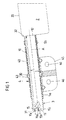
- FIG. 1 are of an airbag module for a motor vehicle, a gas generator 1, a ceremonisublasender by means of the gas generator in a crash case 2 with an airbag cover 20, a fabric layer 3 for electrical insulation of the gas generator 1 and a gas generator 1 associated holding device 4 shown.
- the gas generator 1 is a so-called tubular gas generator, which is surrounded by a tubular, substantially hollow cylindrical metallic housing 10 and with this defining a cylindrical surface generator housing 10 of length I between a first end-side top surface 11 and a second end face Deck surface 12 along an axis A extends.
- the gas generator 1 is used to inflate the associated airbag 2 in a crash case by the shell 20 of the airbag 2 (airbag shell) is filled by means of the gas generator 1 with gas.
- the gas bag 2 is located here in front of the second front-side cover surface 12 of the gas generator 1 by way of example.
- gas generator 1 From the gas bag 2 is in the direction of the gas generator 1 from an educated as an extension airbag section 3, which forms a gas generator 1 enclosing the flexible protective cover 30 which, like the airbag cover 20 of a fabric or, more precisely, is formed together with the airbag skin 20 from a suitable (uniform) tissue.
- the extension 3 of the airbag 2 forming flexible protective cover 30 extends as well as the (tubular) gas generator 1 between a first top surface 31 and a second top surface 32, wherein the first (open) top surface 31 of the flexible protective cover 30, the first end-side top surface 11 of Surrounding gas generator 1 and the second (also open) top surface 32 of the flexible protective cover 3 is located on the second end-side cover surface 12 of the gas generator 1 and forms a transition to the airbag cover 20.
- the flexible protective cover 30 of the gas generator 1 is a substantially hollow cylindrical extension of the airbag 2, such that the airbag cover 20 and the flexible protective cover 30 form a common cavity and that region of the cavity, which is enclosed by the airbag cover 20 , for filling with gas in a crash case, while that portion of the cavity, which is enclosed by the flexible protective cover 30, the inclusion of the gas generator 1 is used, wherein the flexible protective cover 30, the generator housing 10 so tightly encloses that the flexible protective cover 30 rests on the generator housing 10.
- the gas generator 1 or its housing 10 is electrically insulated from adjacent (metallic) components. This applies in particular to components of a holding device 4, via which the gas generator 1 can be fixed in a motor vehicle in a defined position.
- the holding device 4 has a gas generator 1 annularly at an angle of less than 360 °, but preferably at an angle of at least 180 ° surrounding clamping portion 40 by means of two Kiemmimplantation 5a, 5b in the form of clamping rings on the gas generator 1 and more precisely whose housing 10 is clamped.
- the gas generator 1 enclosing the flexible shell 30 extends between the housing 10 of the gas generator 1 on the one hand and the said components 5a, 5b, 40 of the holding device 4 on the other hand, so that these typically made of metal components have no direct contact with the metallic generator housing 10 ,
- the clamping portion 40 of the holding device 4 also has an annular circumferential projection 43 into which a bead of the generator housing 10 can engage to secure the clamping portion 40 in the axial direction (along the longitudinal axis A of the gas generator 1).
- clamping portion 40 of the holding device 4 is from a connecting portion 45, via which the clamped in the clamping portion 40 of the holding device 4 gas generator 1 is fixed to a supporting motor vehicle part, for which in the connecting portion 45 mounting holes 46 are provided by suitable fasteners, eg. B. in the form of screws can be penetrated.
- the flexible protective cover 30 is adapted in its cross section to the outer contour of the gas generator 1 facing it and the holding device 4 comprises the gas generator 1 and the flexible sleeve 30 with its clamping portion 40, the flexible sleeve 30 lies against the gas generator 1, more precisely at its formed by the generator housing 10 on the outside, so that the flexible protective cover 30 is filled by the gas generator 1 substantially completely, and even then, even if the airbag cover 20 is filled during inflation of the airbag 2 with gas.
- the gas generator 1 On its side facing away from the gas bag 2, the first end-side top surface 11, the gas generator 1 has a connector portion 15 which enables the electrical connection of a control unit with which the gas generator in response to output signals of one or more crash or pre-crash sensors triggered or is ignitable.
- a control unit with which the gas generator in response to output signals of one or more crash or pre-crash sensors triggered or is ignitable.
- electrical connecting lines electrical cables
- the plug region 15 of the gas generator 1 is here a multi-pin connector area, in addition to the electrical connection lines to an associated control unit and a grounding line is connected to ground the gas generator. This is combined with the isolation of the Gas generator 1 through the flexible protective cover 30 reaches a targeted, defined grounding of the gas generator 1.
- the plug region 15 of the gas generator 1 in the present case comprises three plug elements 15a, 15b, 15c, of which two plug elements 15a, 15b are provided in the form of plug pins for electrical connection of the gas generator 1 to an associated control unit (via electrical connection lines) and a further plug element 15c is used to ground the gas generator 1 via a to be connected to that connector element 15c and grounding therefrom, which is fed to a central vehicle ground.
- the third plug element 15c is in electrical contact with the (metallic) gas generator housing 10 and may be formed, for example, by an electrical contact section on the inner wall of the plug region 15 and / or on its front side. Both variants are in FIG. 1 indicated.
- FIG. 2 is a modification of the embodiment FIG. 1 represented, with a difference that according to FIG. 2 the gas bag 2 is surrounded by a folded or gathered state of an envelope 6 formed by a film 60 in an airbag package. This keeps the gas bag 2 in a compressed state to a package state and thus facilitates the stowage of the airbag 2 in a motor vehicle.
- the airbag 2 When inflating the airbag 2 in a crash case by the gas bag shell 20 surrounded by the interior of the airbag 2 is filled with gas, the airbag 2 unfolds, the envelope formed by the film 60 6 travels, so that the airbag. 2 emerge from the enclosure 6 and can form a cushion for serving a vehicle occupant.
- FIG. 1 shown embodiment consists in the generator assembly FIG. 2 in that the flexible protective cover 30 serving to isolate the gas generator 1 from adjacent components is not formed by an extension of the airbag 2 inflatable in a crash to a gas cushion but rather by an extension 3 of the envelope 6 surrounding the airbag 2 in a compressed state , D. h.,
- the extension 3 is connected to the envelope 6 forming film 60 (one piece), so that he preferably also is formed as a film part, and is from that film 60 in the direction of the gas generator 2 from.
- a transition region to the envelope 6 of the airbag 2 or, more precisely, to the envelope 6 forming the film 60 is formed on the second end-side cover surface 32 of the flexible shell 30.
- the airbag 2 or the airbag cover 20 in this case surrounds the gas generator 1 only partially in the region of its end face 12 facing the airbag 2 with an injection mouth 25 of the airbag 2.
- the above-described electrical insulation of the gas generator 1 with respect to adjacent components is independent of whether it is a hot gas generator which generates (chemically) hot gases to ignite the airbag 2 when ignited from a mixture of substances, or a cold gas generator which is ignited a gas already stored in the gas generator for inflating the airbag 2 releases, or to a so-called hybrid gas generator containing both a stored, releasable for inflating the airbag 2 cold gas and serving for generating additional hot gases mixture.
Landscapes
- Engineering & Computer Science (AREA)
- Mechanical Engineering (AREA)
- Air Bags (AREA)
Description
- Die Erfindung betrifft eine Generatorbaugruppe für ein Airbagmodul eines Kraftfahrzeugs nach dem Oberbegriff des Anspruchs 1.
- Eine derartige Generatorbaugruppe umfasst einen Gasgenerator zum Aufblasen eines eine Gassackhülle aufweisenden Gassackes des Airbagmodules mit Gas und Mittel zur elektrischen Isolierung des (ein metallisches Gehäuse aufweisenden) Gasgenerators gegenüber angrenzenden (metallischen) Bauelementen des Airbagmodules. Derartige Generatorbaugruppen sind beispielsweise aus den Druckschriften
DE 102 34 502 A1 undDE 103 57 867 A1 bekannt. - Ein Airbagmodul, in dem die genannte Generatorbaugruppe Verwendung finden kann, dient zum Schutz von Fahrzeuginsassen in einem Crash-Fall. Hierzu ist der Gasgenerator des Airbagmodules mit einem oder mehreren Crash- und/oder Pre-Crash-Sensoren gekoppelt, die bei einer Crash-bedingten starken Fahrzeugverzögerung bzw. einem anhand von Sensordaten ermittelten bevorstehenden Crash eine Zündung des Gasgenerators bewirken, so dass dieser ein Gas zum Aufblasen des Gassackes freisetzt. Der zunächst in zusammengefaltetem bzw. zusammengerafftem Zustand im Airbagmodul vorgesehene Gassack entfaltet sich beim Aufblasen und bildet im aufgeblasenen Zustand ein Gaskissen, das einen oder mehrere Fahrzeuginsassen vor einem Auftreffen auf die Fahrzeugkarosserie schützen soll.
- Um den Gasgenerator beim Auftreten eines mittels hierfür vorgesehener Sensoren detektierten (bevorstehenden) Unfalls auslösen zu können, ist jener in der Regel elektrisch, d.h., über elektrische Leitungen, mit einer Steuereinrichtung verbunden, die aufgrund entsprechender Sensorsignale eine Zündung des Gasgenerators bewirkt.
- In vielen Anwendungsfällen wird hierbei angestrebt, den Gasgenerator, d.h., insbesondere ein metallisches Gehäuse des Gasgenerators, gegenüber angrenzenden (metallischen) Bauelenenten elektrisch zu isolieren, so dass eine notwendige Erdung des Gasgenerators ausschließlich gezielt erfolgt. Zur Isolierung eines Gasgenerators gegenüber umgebenden Bauteilen ist es bekannt, Montageteile und Befestigungselemente, die mit dem Gasgenerator, also insbesondere dessen (metallischem) Gehäuse, in Kontakt stehen, elektrisch isolierend auszubilden und beispielsweise mit angespritzten Kunststoffbereichen zu versehen. Dies bedingt allerdings einen erhöhten Aufwand bei der Fertigung und erfordert die Verwendung komplizierter Montageteile und Befestigungselemente.
- Der Erfindung liegt daher das Problem zugrunde, eine Generatorbaugruppe der eingangs genannten Art zu schaffen, die sich bei einfachem Aufbau durch eine zuverlässige elektrische Isolierung des Gasgenerators auszeichnet.
- Dieses Problem wird erfindungsgemäß durch die Schaffung einer Generatorbaugruppe mit den Merkmalen des Anspruchs 1 gelöst.
- Zur elektrischen Isolierung des Gasgenerators ist eine flexible Materiallage, insbesondere in Form einer Gewebelage, vorgesehen, die den Gasgenerator (an einer Außenseite des Gasgenerators) entlang einer Umfangsrichtung vollständig umschließt. Die Erdung eines gegenüber umgebenden Bauteilen elektrisch isolierten Gasgenerators erfolgt durch eine Erdungsleitung, die einen (mehrpoligen) Steckerbereich des Gasgenerators kontaktiert, welcher auch zur Zündung des Gasgenerators mittels sensorgesteuerter elektrischer Signale dient.
- Indem der Gasgenerator auf seiner durch ein (metallisches) Gehäuse gebildeten Außenseite von einer flexiblen Materiallage umgeben ist, wird ein unmittelbarer Kontakt benachbarter (metallischer) Bauelemente mit dem Gasgenerator verhindert, da ja die flexible Materiallage den Gasgenerator gegenüber solchem Kontakt abschirmt, indem sie zwischen der durch das (metallische) Generatorgehäuse gebildeten Außenseite des Gasgenerators und daran angrenzenden sonstigen Bauelementen liegt.
- Vorteilhaft ist eine Ausführungsform, bei der die flexible Materiallage eine den Gasgenerator in Umfangsrichtung umgebende flexible Hülle bildet, die beispielsweise auf den zugeordneten Gasgenerator aufgeschoben werden kann.
- Die erfindungsgemäße Anordnung zur Isolierung eines Gasgenerators ist z.B. geeignet zur Verwendung bei Gasgeneratoren, die sich entlang einer Achse erstrecken, wie z. B. einem so genannten Rohrgasgenerator, der eine im Wesentlichen zylindrische Mantelfläche aufweist, die sich zwischen einer ersten und einer zweiten stirnseitigen Deckfläche erstreckt. In einem solchen Fall kann eine (bei bestimmungsgemäßer Anordnung auf dem zugeordneten Gasgenerator) einen Hohlzylinder bildende, an mindestens einer Deckfläche offene Hülle aus einem flexiblen Material in einfacher Weise über den Gasgenerator gezogen werden.
- Ein maximaler Schutz des Gasgenerators vor elektrischem Kontakt mit benachbarten Bauelementen wird dabei erreicht, wenn sich die flexible Materiallage bzw. Hülle entlang der Längsachse des Gasgenerators im Wesentlichen entlang der gesamten Länge des Gasgenerators erstreckt, so dass die Mantelfläche des Gasgenerators entlang ihrer gesamten Länge (also vollständig) von der flexiblen Materiallage bedeckt ist.
- Bei der flexiblen Materiallage kann es sich einerseits um einen Abschnitt des mittels des Gasgenerators aufzublasenden Gassackes des Airbagmodules handeln, beispielsweise indem ein Abschnitt (Fortsatz) des Gassackes so ausgebildet ist, dass er den Gasgenerator zur Isolierung gegenüber benachbarten Bauelementen umgibt. Diese Anordnung ist zu unterscheiden von dem bekannten Fall, dass ein Gasgenerator innerhalb des hiermit aufzublasenden Gassackes angeordnet wird. Denn im letztgenannten Fall dient der den Gasgenerator umgebende Gassack nicht zur elektrischen Isolierung des Gasgenerators gegenüber benachbarten metallischen Bauteilen. Wesentlich für die flexible Materiallage gemäß der vorliegenden Erfindung ist nämlich, dass diese den Gasgenerator auch dann noch eng umfasst bzw. an diesem anliegt, um ihn vor unmittelbarem Kontakt mit benachbarten Bauelementen zu schützen, wenn der Gassack in einem Crash-Fall aufgeblasen wird und sich hierbei entfaltet. D.h. die flexible Materiallage umgibt den Gasgenerator (dauerhaft, d.h. auch beim Aufblasen des Gassackes) im Querschnitt im Wesentlichen konzentrisch; und die flexible Materiallage behält beim Aufblasen des Gassackes ihre ursprüngliche räumliche Lage (an der Außenseite des Gasgenerators) bei, ohne sich zu entfalten bzw. sich substanziell von dem Gasgenerator (speziell der ihr zugewandten Außenseite des Gasgenerators) zu entfernen, so dass ein von der flexiblen Materiallage definierter Hohlraum von dem Gasgenerator im Wesentlichen vollständig ausgefüllt wird.
- Andererseits kann es sich bei der den Gasgenerator gegenüber seiner Umgebung isolierenden flexiblen Materiallage auch um eine vom Gassack separate Lage handeln, die nicht mit dem aufzublasenden Gassack verbunden ist. So kann die flexible Materiallage beispielsweise einen Bestandteil einer den Gassack im zusammengefalteten Zustand umgebenden Umhüllung bilden. Eine derartige Umhüllung dient dazu, den zu einem Gassackpaket zusammengefalteten bzw. zusammengerafften Gassack aufzunehmen, um das Verstauen des Gassackpaketes im Kraftfahrzeug zu erleichtern. Eine solche Umhüllung des Gassackes kann beispielsweise aus einer Folie bestehen, die beim Aufblasen und Entfalten des Gassackes zerreißt.
- Es ist jedoch auch möglich, dass die den Gasgenerator gegenüber seiner Umgebung isolierende flexible Materiallage keinen Bestandteil einer anderen Komponente des Airbagmodules bildet, sondern als eine eigenständige Modulkomponente vorgesehen ist.
- Die flexible Materiallage dient insbesondere dazu, einen unmittelbaren Kontakt der Oberfläche (Außenseite) des Gasgenerators mit Komponenten einer Halteeinrichtung zu verhindern, über die der Gasgenerator mit einem zugeordneten tragenden Kraftfahrzeugteil verbunden wird, um dessen Position innerhalb des Kraftfahrzeugs zu fixieren, wobei es sich bei dem tragenden Kraftfahrzeugteil auch um eine Komponente des Airbagmodules, etwa um ein Gehäuseteil des Airbagmodules, handeln kann. Die flexible Materiallage erstreckt sich hierzu zwischen dem Gasgenerator und der Halteeinrichtung, so dass ein unmittelbarer Kontakt des Gasgenerators mit der zugeordneten Halteeinrichtung, die aus Stabilitätsgründen regelmäßig aus Metall besteht, vermieden wird.
- Die Halteeinrichtung kann beispielsweise einen den Gasgenerator zumindest teilweise umschließenden Klemmabschnitt umfassen, der mittels zugeordneter Klemmelemente am Gasgenerator festgeklemmt wird, wobei sich die flexible Materiallage zwischen dem Klemmabschnitt der Halteeinrichtung und der Außenseite des Gasgenerators erstreckt.
- Weitere Einzelheiten und Vorteile der Erfindung werden bei der nachfolgenden Beschreibung von Ausführungsbeispielen anhand der Figuren deutlich werden.
- Es zeigen:
- Fig. 1
- einen Schnitt durch eine Gasgeneratorbaugruppe eines Airbagmodules für ein Kraftfahrzeug;
- Fig. 2
- eine Abwandlung der Gasgeneratorbaugruppe aus
Figur 1 in einem Schnitt. - In
Figur 1 sind von einem Airbagmodul für ein Kraftfahrzeug ein Gasgenerator 1, ein mittels des Gasgenerators in einem Crash-Fall aufzublasender Gassack 2 mit einer Gassackhülle 20, eine Gewebelage 3 zur elektrischen Isolierung des Gasgenerators 1 sowie eine dem Gasgenerator 1 zugeordnete Halteeinrichtung 4 dargestellt. - Bei dem Gasgenerator 1 handelt es sich um einen so genannten Rohrgasgenerator, der von einem rohrförmigen, im Wesentlichen höhlzylindrischen metallischen Gehäuse 10 umgeben ist und der sich mit diesem eine zylindrische Mantelfläche definierenden Generatorgehäuse 10 der Länge I zwischen einer ersten stirnseitigen Deckfläche 11 und einer zweiten stirnseitigen Deckfläche 12 entlang einer Achse A erstreckt.
- Der Gasgenerator 1 dient zum Aufblasen des zugeordneten Gassackes 2 in einem Crash-Fall, indem die Hülle 20 des Gassackes 2 (Gassackhülle) mittels des Gasgenerators 1 mit Gas befüllt wird. Der Gassack 2 befindet sich dabei vorliegend beispielhaft vor der zweiten stirnseitigen Deckfläche 12 des Gasgenerators 1.
- Von dem Gassack 2 steht in Richtung des Gasgenerators 1 ein als Fortsatz ausgebildeter Gassackabschnitt 3 ab, der eine den Gasgenerator 1 umschließende flexible Schutzhülle 30 bildet, die ebenso wie die Gassackhülle 20 aus einem Gewebe besteht bzw. genauer gesagt zusammen mit der Gassackhülle 20 aus einem geeigneten (einheitlichen) Gewebe gebildet ist.
- Die den Fortsatz 3 des Gassackes 2 bildende flexible Schutzhülle 30 erstreckt sich ebenso wie der (rohrförmige) Gasgenerator 1 zwischen einer ersten Deckfläche 31 und einer zweiten Deckfläche 32, wobei die erste (offene) Deckfläche 31 der flexiblen Schutzhülle 30 die erste stirnseitigen Deckfläche 11 des Gasgenerators 1 umgibt und die zweite (ebenfalls offene) Deckfläche 32 der flexiblen Schutzhülle 3 an der zweiten stirnseitigen Deckfläche 12 des Gasgenerators 1 liegt und einen Übergang zu der Gassackhülle 20 ausbildet.
- Konkret handelt es sich bei der flexiblen Schutzhülle 30 des Gasgenerators 1 um einen im Wesentlichen hohlzylindrischen Fortsatz des Gassackes 2, derart, dass die Gassackhülle 20 und die flexible Schutzhülle 30 einen gemeinsamen Hohlraum bilden und derjenige Bereich des Hohlraumes, der von der Gassackhülle 20 umschlossen wird, zum Befüllen mit Gas in einem Crash-Fall dient, während derjenige Bereich des Hohlraumes, der von der flexiblen Schutzhülle 30 umschlossen ist, der Aufnahme des Gasgenerators 1 dient, wobei die flexible Schutzhülle 30 das Generatorgehäuse 10 derart eng umschließt, dass die flexible Schutzhülle 30 am Generatorgehäuse 10 anliegt.
- Hierdurch ist der Gasgenerator 1 bzw. dessen Gehäuse 10 gegenüber angrenzenden (metallischen) Bauelementen elektrisch isoliert. Dies gilt insbesondere für Komponenten einer Halteeinrichtung 4, über die der Gasgenerator 1 in einem Kraftfahrzeug in definierter Position fixierbar ist.
- Die Halteeinrichtung 4 weist eine den Gasgenerator 1 ringförmig unter einem Winkel von weniger als 360°, jedoch bevorzugt unter einem Winkel von mindestens 180° umschließenden Klemmabschnitt 40 auf, der mittels zweier Kiemmelemente 5a, 5b in Form von Klemmringen am Gasgenerator 1 bzw. genauer an dessen Gehäuse 10 festgeklemmt ist. Dabei erstreckt sich die den Gasgenerator 1 umschließende flexible Hülle 30 zwischen dem Gehäuse 10 des Gasgenerators 1 einerseits und den besagen Komponenten 5a, 5b, 40 der Halteeinrichtung 4 andererseits, so dass diese typischerweise aus Metall bestehenden Bauteile keinen unmittelbaren Kontakt mit dem metallischen Generatorgehäuse 10 haben.
- Der Klemmabschnitt 40 der Halteeinrichtung 4 weist zudem eine ringförmig umlaufende Erhebung 43 auf, in die eine Wulst des Generatorgehäuses 10 eingreifen kann, um den Klemmabschnitt 40 in axialer Richtung (entlang der Längsachse A des Gasgenerators 1) zu sichern.
- Von dem Klemmabschnitt 40 der Halteeinrichtung 4 steht ein Verbindungsabschnitt 45 ab, über den der in dem Klemmabschnitt 40 der Halteeinrichtung 4 festgeklemmte Gasgenerator 1 an einem tragenden Kraftfahrzeugteil fixierbar ist, wozu in dem Verbindungsabschnitt 45 Befestigungsöffnungen 46 vorgesehen sind, die von geeigneten Befestigungsmitteln, z. B. in Form von Schrauben, durchgriffen werden können.
- Da die flexible Schutzhülle 30 in ihrem Querschnitt an die ihr zugewandte äußere Kontur des Gasgenerators 1 angepasst ist und die Halteeinrichtung 4 den Gasgenerator 1 sowie die flexible Hülle 30 mit ihrem Klemmabschnitt 40 klemmend umfasst, liegt die flexible Hülle 30 am Gasgenerator 1, genauer an dessen durch das Generatorgehäuse 10 gebildeter Außenseite an, so dass die flexible Schutzhülle 30 durch den Gasgenerator 1 im wesentlichen vollständig ausgefüllt wird, und zwar auch dann noch, wenn die Gassackhülle 20 beim Aufblasen des Gassackes 2 mit Gas befüllt wird.
- An seiner dem Gassack 2 abgewandten, ersten stirnseitigen Deckfläche 11 weist der Gasgenerator 1 einen Steckerbereich 15 auf, der den elektrischen Anschluss eines Steuergerätes ermöglicht, mit dem der Gasgenerator in Abhängigkeit von Ausgangssignalen eines oder mehrerer Crash- bzw. Pre-Crash-Sensoren auslösbar bzw. zündbar ist. Hierzu dienen elektrische Verbindungsleitungen (elektrische Kabel), die das dem Gasgenerator 1 zugeordnete Steuergerät in bekannter Weise mit dem Gasgenerator 1 elektrisch verbinden und die über Steckerelemente an den Steckerbereich 15 des Gasgenerators 1 anzuschiießen sind.
- Bei dem Steckerbereich 15 des Gasgenerators 1 handelt es sich hier um einen mehrpoligen Steckerbereich, an den neben den elektrischen Verbindungsleitungen zu einem zugeordneten Steuergerät auch eine Erdungsleitung anschließbar ist, um den Gasgenerator erden zu können. Hierdurch wird in Kombination mit der Isolierung des Gasgenerators 1 durch die flexible Schutzhülle 30 eine gezielte, definierte Erdung des Gasgenerators 1 erreicht.
- Konkret umfasst der Steckerbereich 15 des Gasgenerators 1 vorliegend drei Steckerelemente 15a, 15b, 15c, von denen zwei Steckerelemente 15a, 15b in Form von Steckerstiften zum elektrischen Anschluss des Gasgenerators 1 an ein zugeordnetes Steuergerät (über elektrische Verbindungsleitungen) vorgesehen sind und ein weiteres Steckerelement 15c zur Erdung des Gasgenerators 1 über eine an jenes Steckerelement 15c anzuschließende und hiervon abgehende Erdungsleitung dient, welche einer zentralen Fahrzeugerdung zugeführt wird. Das dritte Steckerelement 15c steht hierzu mit dem (metallischen) Gasgeneratorgehäuse 10 in elektrischem Kontakt und kann beispielsweise durch einen elektrischen Kontaktabschnitt an der Innenwand des Steckerbereiches 15 und/oder an dessen Frontseite gebildet sein. Beide Varianten sind in
Figur 1 angedeutet. - In
Figur 2 ist eine Abwandlung des Ausführungsbeispiels ausFigur 1 dargestellt, wobei ein Unterschied darin besteht, dass gemäßFigur 2 der Gassack 2 im zu einem Gassackpaket zusammengefalteten bzw. zusammengerafften Zustand von einer durch eine Folie 60 gebildeten Umhüllung 6 umgeben ist. Diese hält den Gassack 2 im zu einem Paket zusammengestauchten Zustand und erleichtert somit das Verstauen des Gassackes 2 in einem Kraftfahrzeug. - Beim Aufblasen des Gassackes 2 in einem Crash-Fall, indem der von der Gassackhülle 20 umgebene Innenraum des Gassackes 2 mit Gas befüllt wird, wobei der Gassack 2 sich entfaltet, reist die durch die Folie 60 gebildete Umhüllung 6 auf, so dass der Gassack 2 aus der Umhüllung 6 austreten und ein zum Schutz eines Fahrzeuginsassen dienendes Gaskissen bilden kann.
- Ein weiterer Unterschied zu dem in
Figur 1 gezeigten Ausführungsbeispiel besteht bei der Generatorbaugruppe ausFigur 2 darin, dass die zur Isolierung des Gasgenerators 1 gegenüber benachbarten Bauteilen dienende flexible Schutzhülle 30 nicht durch einen Fortsatz des in einem Crash-Fall zu einem Gaskissen aufblasbaren Gassackes 2 sondern vielmehr durch einen Fortsatz 3 der den Gassack 2 in zusammengestauchtem Zustand umgebenden Umhüllung 6 gebildet wird. D. h., der Fortsatz 3 ist mit der jene Umhüllung 6 bildenden Folie 60 (einstückig) verbunden, so dass er bevorzugt ebenfalls als Folienteil ausgebildet ist, und steht von jener Folie 60 in Richtung auf den Gasgenerator 2 ab. Dabei ist an der zweiten stirnseitigen Deckfläche 32 der flexiblen Hülle 30 ein Übergangsbereich zu der Umhüllung 6 des Gassackes 2 bzw. genauer zu der diese Umhüllung 6 bildenden Folie 60 ausgebildet. - Der Gassack 2 bzw. die Gassackhülle 20 umgibt in diesem Fall den Gasgenerator 1 lediglich abschnittsweise im Bereich von dessen dem Gassack 2 zugewandter stirnseitiger Deckfläche 12 mit einem Einblasmund 25 des Gassackes 2.
- Die vorstehend beschriebene elektrische Isolation des Gasgenerators 1 gegenüber benachbarten Bauelementen ist unabhängig davon, ob es sich hierbei um einen Heißgasgenerator handelt, der bei Zündung aus einem Stoffgemisch (chemisch) heiße Gase zum Aufblasen des Gassackes 2 erzeugt, oder um einen Kaltgasgenerator, der bei Zündung ein bereits im Gasgenerator gespeichertes Gas zum Aufblasen des Gassackes 2 freisetzt, oder um einen so genannten Hybrid-Gasgenerator, der sowohl ein gespeichertes, zum Aufblasen des Gassackes 2 freisetzbares Kaltgas als auch ein zur Erzeugung zusätzlicher Heißgase dienendes Stoffgemisch enthält.
Claims (15)
- Generatorbaugruppe für ein Airbagmodul eines Kraftfahrzeugs, mit- einem Gasgenerator (1) zum Aufblasen eines Gassackes des Airbagmodules mit Gas, wobei der Gasgenerator (1) mit seinem Generatorgehäuse (10) eine Mantelfläche definiert, die sich zwischen einer ersten und einer zweiten stirnseitigen Deckfläche (11, 12) des Gasgenerators (1) erstreckt, und- Mitteln zur elektrischen Isolierung des Gasgenerators gegenüber angrenzenden Bauelementen, wobei zur elektrischen Isolierung des Gasgenerators eine flexible Materiallage (30) vorgesehen ist, die die Mantelfläche des Gasgenerators (1) vollständig bedeckt,dadurch gekennzeichnet,
dass eine gezielte, definierte Erdung des Gasgenerators (1) über eine Erdungsleitung erfolgt, die an einen in einen Steckerbereich (15) des Gasgenerators (1) integrierten elektrischen Anschluss (15c) des Gasgenerators (1) angeschlossen ist. - Generatorbaugruppe nach Anspruch 1, dadurch gekennzeichnet, dass die flexible Materiallage (30) den Gasgenerator (1) als flexible Hülle entlang der Umfangsrichtung umschließt, wobei die flexible Hülle (30) insbesondere einen Hohlzylinder definiert und sich insbesondere zwischen zwei einander gegenüberliegenden, jeweils eine Deckfläche bildenden Stirnseiten (31, 32) erstreckt, von denen zumindest eine Deckfläche (31) offen ist.
- Generatorbaugruppe nach einem der vorhergehenden Ansprüche, dadurch gekennzeichnet, dass sich der Gasgenerator (1) entlang einer Achse (A) erstreckt.
- Generatorbaugruppe nach Anspruch 3, dadurch gekennzeichnet, dass sich die flexible Materiallage (30) in Richtung der Generatorachse (A) im Wesentlichen entlang der gesamten Länge (I) des Gasgenerators (1) erstreckt.
- Generatorbaugruppe nach einem der vorhergehenden Ansprüche, dadurch gekennzeichnet, dass die flexible Materiallage (30) beim Aufblasen des Gassackes (2) ihre räumliche Lage vor der ihr zugewandten Außenseite des Gasgenerators (1) beibehält.
- Generatorbaugruppe nach einem der vorhergehenden Ansprüche, dadurch gekennzeichnet, dass die flexible Materiallage (30) durch einen Abschnitt (3) des Gassackes (2), insbesondere durch einen Fortsatz der Gassackhülle (20) gebildet wird.
- Generatorbaugruppe nach Anspruch 6, dadurch gekennzeichnet, dass die flexible Materiallage (30) zusammen mit der Gassackhülle (20) einen Hohlraum definiert, dessen einer Hohlraumbereich von der Gassackhülle (20) umschlossen ist und beim Aufblasen des Gassackes (2) mit Gas befüllt wird und dessen anderer Hohlraumbereich von der flexiblen Materiallage (30) umschlossen ist und von dem Gasgenerator (1) im Wesentlichen vollständig ausgefüllt ist.
- Generatorbaugruppe nach einem der Ansprüche 1 bis 5, dadurch gekennzeichnet, dass die flexible Materiallage (30) als eine von der Gassackhülle (20) separate Komponente ausgebildet ist.
- Generatorbaugruppe nach einem der vorhergehenden Ansprüche, dadurch gekennzeichnet, dass der Gassack (2) vor dem Aufblasen zu einem Gassackpaket zusammengestaucht und von einer Umhüllung (6) umgeben ist.
- Generatorbaugruppe nach Anspruch 9, dadurch gekennzeichnet, dass die flexible Materiallage (30) durch einen Abschnitt (3) der Umhüllung (6) des Gassackes (2) gebildet wird.
- Generatorbaugruppe nach einem der vorhergehenden Ansprüche, dadurch gekennzeichnet, dass die Umhüllung (6) des Gassackes (2) und/oder die flexible Materiallage (30) aus einem Folienmaterial bestehen.
- Generatorbaugruppe nach einem der vorhergehenden Ansprüche, dadurch gekennzeichnet, dass die Gassackhülle (20) und/oder die flexible Materiallage (30) aus einem Gewebe bestehen.
- Generatorbaugruppe nach einem der vorhergehenden Ansprüche, dadurch gekennzeichnet, dass dem Gasgenerator (1) eine Halteeinrichtung (4) zugeordnet ist, mit der der Gasgenerator (1) an einem zugeordneten Kraftfahrzeugteil fixierbar ist.
- Generatorbaugruppe nach einem der vorhergehenden Ansprüche, dadurch gekennzeichnet, dass an den Steckerbereich (15) eine elektrische Verbindungsleitung anzuschließen ist, um den Gasgenerator (1) elektrisch auslösen zu können, so dass er ein Gas zum Aufblasen des Gassackes (2) freisetzt.
- Generatorbaugruppe nach einem der vorhergehenden Ansprüche, dadurch gekennzeichnet, dass der elektrische Anschluss (15c) in elektrischem Kontakt mit einem metallischen Gehäuse (10) des Gasgenerators (1) steht.
Applications Claiming Priority (2)
| Application Number | Priority Date | Filing Date | Title |
|---|---|---|---|
| DE202006019196U DE202006019196U1 (de) | 2006-12-15 | 2006-12-15 | Generatorbaugruppe für ein Airbagmodul eines Kraftfahrzeugs |
| PCT/EP2007/062627 WO2008071525A1 (de) | 2006-12-15 | 2007-11-21 | Generatorbaugruppe für ein airbagmodul eines kraftfahrzeugs |
Publications (2)
| Publication Number | Publication Date |
|---|---|
| EP2099656A1 EP2099656A1 (de) | 2009-09-16 |
| EP2099656B1 true EP2099656B1 (de) | 2013-01-02 |
Family
ID=37983079
Family Applications (1)
| Application Number | Title | Priority Date | Filing Date |
|---|---|---|---|
| EP07822773A Active EP2099656B1 (de) | 2006-12-15 | 2007-11-21 | Generatorbaugruppe für ein airbagmodul eines kraftfahrzeugs |
Country Status (6)
| Country | Link |
|---|---|
| US (1) | US8047562B2 (de) |
| EP (1) | EP2099656B1 (de) |
| JP (1) | JP5230643B2 (de) |
| CN (1) | CN101583521B (de) |
| DE (1) | DE202006019196U1 (de) |
| WO (1) | WO2008071525A1 (de) |
Families Citing this family (3)
| Publication number | Priority date | Publication date | Assignee | Title |
|---|---|---|---|---|
| KR100962140B1 (ko) * | 2008-07-10 | 2010-06-10 | 현대자동차주식회사 | 차량의 혼 신호용 스위치 장치 |
| DE102009046841B4 (de) * | 2009-11-18 | 2017-04-27 | TAKATA Aktiengesellschaft | Airbag für ein Kraftfahrzeug |
| KR102038859B1 (ko) * | 2012-03-27 | 2019-10-31 | 주식회사 다이셀 | 가스 발생기 |
Family Cites Families (23)
| Publication number | Priority date | Publication date | Assignee | Title |
|---|---|---|---|---|
| DE19742204B4 (de) * | 1997-09-24 | 2006-07-13 | Trw Airbag Systems Gmbh & Co. Kg | Gasgenerator für eine Sicherheitseinrichtung |
| JP2000085510A (ja) | 1998-09-14 | 2000-03-28 | Takata Kk | エアバッグ装置とインフレータとの連結構造 |
| DE19846110A1 (de) | 1998-10-07 | 2000-04-20 | Bosch Gmbh Robert | Zündvorrichtung für Rückhaltemittel in einem Fahrzeug |
| JP3491228B2 (ja) * | 2000-05-26 | 2004-01-26 | 豊田合成株式会社 | 頭部保護エアバッグ装置 |
| DE10030471C1 (de) * | 2000-06-21 | 2001-07-26 | Bosch Gmbh Robert | Airbagmodul |
| US6450529B1 (en) | 2000-06-23 | 2002-09-17 | Breed Automotive Technologies, Inc. | Inflatable side air bag curtain module with chamber separators |
| DE10114208A1 (de) | 2001-03-23 | 2002-05-08 | Trw Automotive Safety Sys Gmbh | Gassack-Modul |
| US7654555B2 (en) * | 2001-12-12 | 2010-02-02 | Takata-Petri Ag | Module for an occupant-protection device of a motor vehicle |
| DE10234502A1 (de) | 2001-12-12 | 2003-07-03 | Takata Petri Gmbh Ulm | Modul für eine Insassenschutzvorrichtung eines Kraftfahrzeugs |
| DE10223829A1 (de) | 2002-05-28 | 2003-12-11 | Takata Petri Gmbh Ulm | Gasgenerator für einen Airbag |
| AU2003237652A1 (en) | 2002-06-07 | 2003-12-22 | Autoliv Development Ab | Electrically insulated fixing device for an airbag module |
| DE20220428U1 (de) | 2002-06-07 | 2003-07-17 | Autoliv Dev | Elektrisch isolierte Befestigungsanordnung für ein Airbagmodul |
| JP4059124B2 (ja) * | 2003-03-27 | 2008-03-12 | 豊田合成株式会社 | サイドエアバッグ装置及びそれに用いるラッピングシート |
| DE10357867B4 (de) | 2003-12-11 | 2006-08-10 | Autoliv Development Ab | Airbagmodul-Befestigungsanordnung mit Massekabel |
| US7384062B2 (en) | 2004-01-28 | 2008-06-10 | Nihon Plast Co., Ltd. | Airbag system |
| DE102004010144B4 (de) * | 2004-02-27 | 2006-03-23 | Zf Friedrichshafen Ag | Anordnung zur Festlegung des Gasgenerators einer Airbageinheit |
| DE102004015755B3 (de) | 2004-03-31 | 2005-09-08 | Autoliv Development Ab | Airbagmodul für Fahrzeuge |
| DE102005031108A1 (de) | 2004-07-09 | 2006-01-26 | Trw Automotive Gmbh | Gassackmodul |
| DE202004010785U1 (de) * | 2004-07-09 | 2004-11-25 | Trw Automotive Gmbh | Gassackmodul |
| DE202004016975U1 (de) * | 2004-11-01 | 2004-12-30 | Autoliv Development Ab | Airbagvorrichtung mit einem zerstörbaren Verbindungsabschnitt zwischen einem Gasgenerator und einer nichtmetallischen Gaslanze |
| DE102005004452A1 (de) | 2005-02-01 | 2006-08-10 | Adam Opel Ag | Airbaggehäuse, Airbagmodul und Sicherheitsanordnung zur Gewährleistung der ordnungsgemäßen Funktion des Gasgenerators in einem Airbagmodul und Verfahren zur Herstellung eines solchen Airbaggehäuses |
| DE202005011878U1 (de) * | 2005-07-21 | 2005-10-13 | Takata-Petri Ag | Airbagmodul für ein Kraftfahrzeug |
| DE202006002871U1 (de) | 2006-02-23 | 2006-05-04 | Autoliv Development Ab | Gassackanordnung |
-
2006
- 2006-12-15 DE DE202006019196U patent/DE202006019196U1/de not_active Expired - Lifetime
-
2007
- 2007-11-21 US US12/448,196 patent/US8047562B2/en not_active Expired - Fee Related
- 2007-11-21 CN CN200780046350XA patent/CN101583521B/zh not_active Expired - Fee Related
- 2007-11-21 JP JP2009540693A patent/JP5230643B2/ja not_active Expired - Fee Related
- 2007-11-21 WO PCT/EP2007/062627 patent/WO2008071525A1/de active Application Filing
- 2007-11-21 EP EP07822773A patent/EP2099656B1/de active Active
Also Published As
| Publication number | Publication date |
|---|---|
| JP2010513106A (ja) | 2010-04-30 |
| US20090302586A1 (en) | 2009-12-10 |
| CN101583521A (zh) | 2009-11-18 |
| CN101583521B (zh) | 2012-10-24 |
| EP2099656A1 (de) | 2009-09-16 |
| DE202006019196U1 (de) | 2007-04-12 |
| US8047562B2 (en) | 2011-11-01 |
| JP5230643B2 (ja) | 2013-07-10 |
| WO2008071525A1 (de) | 2008-06-19 |
Similar Documents
| Publication | Publication Date | Title |
|---|---|---|
| EP1296857B1 (de) | Gassack für eine insassen-schutzeinrichtung | |
| DE69925403T2 (de) | Zünder für Aufblasvorrichtung mit Einsatzkörper | |
| DE60124374T2 (de) | Zünderkonstruktion mit Aktivierungsschaltung | |
| DE60204742T2 (de) | Gasgenerator für Air-bag | |
| EP1896299B1 (de) | Gassackanordnung für ein airbagmodul eines kraftfahrzeugs | |
| DE112004000592T5 (de) | Pyrotechnischer Gasgenerator für ein Fahrzeug-Airbag-System | |
| DE4113591A1 (de) | Lenkrad mit einem luftsacksystem | |
| EP2099656B1 (de) | Generatorbaugruppe für ein airbagmodul eines kraftfahrzeugs | |
| EP1403150A2 (de) | Insassenschutzeinrichtung | |
| EP1010592A2 (de) | Vorrichtung zum Aufblasen eines Fahrzeuginsassen-Rückhaltesystems | |
| EP2059417B1 (de) | Gassackabdeckung | |
| WO2015036527A1 (de) | Airbagsystem, fahrzeugsitz mit einem airbagsystem und verfahren zum aktivieren eines airbagsystems | |
| DE102010040119B4 (de) | Gassack für ein Personen-Schutzsystem eines Fahrzeugs und Verfahren zu dessen Herstellung | |
| DE102017220724A1 (de) | Energiespeicher für ein Kraftfahrzeug sowie entsprechendes Kraftfahrzeug | |
| DE102007009036A1 (de) | Gasgenerator für eine Rückhaltevorrichtung für Fahrzeuge | |
| DE19633696B4 (de) | Airbagabdeckklappe | |
| WO2010121985A1 (de) | Gassackmodul für ein fahrzeuginsassen-rückhaltesystem und verfahren zu dessen herstellung | |
| DE102006006787A1 (de) | Druckgasfüllverfahren | |
| EP0861759B1 (de) | Beifahrer-Airbagmodul | |
| EP1459947B1 (de) | Aufblasvorrichtung für ein Fahrzeuginsassen-Rückhaltesystem | |
| DE10125354C2 (de) | Zündvorrichtung für eine Insassenschutzeinrichtung eines Kraftfahrzeuges | |
| DE102015004166A1 (de) | GASGENERATORBAUGRUPPE, GASSACKMODUL UND PERSONENSCHUTZSYSTEM SOWlE HERSTELLUNGSVERFAHREN | |
| DE102017204497A1 (de) | Zündeinrichtung eines Gasgenerators eines Airbagmodules für ein Kraftfahrzeug | |
| DE102017007380A1 (de) | Instrumententafel für ein Fahrzeug mit einem Beifahrerairbag sowie Verfahren zum Auslösen des Beifahrerairbags | |
| DE102019204475B4 (de) | Gassackmodul für ein Fahrzeuginsassen-Rückhaltesystem eines Kraftfahrzeugs und Verfahren zum Herstellen eines Gassackmoduls |
Legal Events
| Date | Code | Title | Description |
|---|---|---|---|
| PUAI | Public reference made under article 153(3) epc to a published international application that has entered the european phase |
Free format text: ORIGINAL CODE: 0009012 |
|
| 17P | Request for examination filed |
Effective date: 20090702 |
|
| AK | Designated contracting states |
Kind code of ref document: A1 Designated state(s): AT BE BG CH CY CZ DE DK EE ES FI FR GB GR HU IE IS IT LI LT LU LV MC MT NL PL PT RO SE SI SK TR |
|
| DAX | Request for extension of the european patent (deleted) | ||
| RAP1 | Party data changed (applicant data changed or rights of an application transferred) |
Owner name: TAKATA AG |
|
| REG | Reference to a national code |
Ref country code: DE Ref legal event code: R079 Ref document number: 502007011163 Country of ref document: DE Free format text: PREVIOUS MAIN CLASS: B60R0021160000 Ipc: B60R0021217000 |
|
| GRAP | Despatch of communication of intention to grant a patent |
Free format text: ORIGINAL CODE: EPIDOSNIGR1 |
|
| RIC1 | Information provided on ipc code assigned before grant |
Ipc: B60R 21/217 20110101AFI20120625BHEP |
|
| GRAS | Grant fee paid |
Free format text: ORIGINAL CODE: EPIDOSNIGR3 |
|
| GRAA | (expected) grant |
Free format text: ORIGINAL CODE: 0009210 |
|
| AK | Designated contracting states |
Kind code of ref document: B1 Designated state(s): AT BE BG CH CY CZ DE DK EE ES FI FR GB GR HU IE IS IT LI LT LU LV MC MT NL PL PT RO SE SI SK TR |
|
| REG | Reference to a national code |
Ref country code: GB Ref legal event code: FG4D Free format text: NOT ENGLISH |
|
| REG | Reference to a national code |
Ref country code: CH Ref legal event code: EP Ref country code: AT Ref legal event code: REF Ref document number: 591409 Country of ref document: AT Kind code of ref document: T Effective date: 20130115 |
|
| REG | Reference to a national code |
Ref country code: IE Ref legal event code: FG4D Free format text: LANGUAGE OF EP DOCUMENT: GERMAN |
|
| REG | Reference to a national code |
Ref country code: DE Ref legal event code: R096 Ref document number: 502007011163 Country of ref document: DE Effective date: 20130228 |
|
| REG | Reference to a national code |
Ref country code: NL Ref legal event code: VDEP Effective date: 20130102 |
|
| PG25 | Lapsed in a contracting state [announced via postgrant information from national office to epo] |
Ref country code: SI Free format text: LAPSE BECAUSE OF FAILURE TO SUBMIT A TRANSLATION OF THE DESCRIPTION OR TO PAY THE FEE WITHIN THE PRESCRIBED TIME-LIMIT Effective date: 20130102 |
|
| REG | Reference to a national code |
Ref country code: LT Ref legal event code: MG4D |
|
| PG25 | Lapsed in a contracting state [announced via postgrant information from national office to epo] |
Ref country code: BG Free format text: LAPSE BECAUSE OF FAILURE TO SUBMIT A TRANSLATION OF THE DESCRIPTION OR TO PAY THE FEE WITHIN THE PRESCRIBED TIME-LIMIT Effective date: 20130402 Ref country code: SE Free format text: LAPSE BECAUSE OF FAILURE TO SUBMIT A TRANSLATION OF THE DESCRIPTION OR TO PAY THE FEE WITHIN THE PRESCRIBED TIME-LIMIT Effective date: 20130102 Ref country code: ES Free format text: LAPSE BECAUSE OF FAILURE TO SUBMIT A TRANSLATION OF THE DESCRIPTION OR TO PAY THE FEE WITHIN THE PRESCRIBED TIME-LIMIT Effective date: 20130413 Ref country code: CZ Free format text: LAPSE BECAUSE OF FAILURE TO SUBMIT A TRANSLATION OF THE DESCRIPTION OR TO PAY THE FEE WITHIN THE PRESCRIBED TIME-LIMIT Effective date: 20130102 Ref country code: IS Free format text: LAPSE BECAUSE OF FAILURE TO SUBMIT A TRANSLATION OF THE DESCRIPTION OR TO PAY THE FEE WITHIN THE PRESCRIBED TIME-LIMIT Effective date: 20130502 Ref country code: LT Free format text: LAPSE BECAUSE OF FAILURE TO SUBMIT A TRANSLATION OF THE DESCRIPTION OR TO PAY THE FEE WITHIN THE PRESCRIBED TIME-LIMIT Effective date: 20130102 |
|
| PG25 | Lapsed in a contracting state [announced via postgrant information from national office to epo] |
Ref country code: GR Free format text: LAPSE BECAUSE OF FAILURE TO SUBMIT A TRANSLATION OF THE DESCRIPTION OR TO PAY THE FEE WITHIN THE PRESCRIBED TIME-LIMIT Effective date: 20130403 Ref country code: LV Free format text: LAPSE BECAUSE OF FAILURE TO SUBMIT A TRANSLATION OF THE DESCRIPTION OR TO PAY THE FEE WITHIN THE PRESCRIBED TIME-LIMIT Effective date: 20130102 Ref country code: FI Free format text: LAPSE BECAUSE OF FAILURE TO SUBMIT A TRANSLATION OF THE DESCRIPTION OR TO PAY THE FEE WITHIN THE PRESCRIBED TIME-LIMIT Effective date: 20130102 Ref country code: NL Free format text: LAPSE BECAUSE OF FAILURE TO SUBMIT A TRANSLATION OF THE DESCRIPTION OR TO PAY THE FEE WITHIN THE PRESCRIBED TIME-LIMIT Effective date: 20130102 Ref country code: PL Free format text: LAPSE BECAUSE OF FAILURE TO SUBMIT A TRANSLATION OF THE DESCRIPTION OR TO PAY THE FEE WITHIN THE PRESCRIBED TIME-LIMIT Effective date: 20130102 Ref country code: PT Free format text: LAPSE BECAUSE OF FAILURE TO SUBMIT A TRANSLATION OF THE DESCRIPTION OR TO PAY THE FEE WITHIN THE PRESCRIBED TIME-LIMIT Effective date: 20130502 |
|
| PG25 | Lapsed in a contracting state [announced via postgrant information from national office to epo] |
Ref country code: RO Free format text: LAPSE BECAUSE OF FAILURE TO SUBMIT A TRANSLATION OF THE DESCRIPTION OR TO PAY THE FEE WITHIN THE PRESCRIBED TIME-LIMIT Effective date: 20130102 Ref country code: DK Free format text: LAPSE BECAUSE OF FAILURE TO SUBMIT A TRANSLATION OF THE DESCRIPTION OR TO PAY THE FEE WITHIN THE PRESCRIBED TIME-LIMIT Effective date: 20130102 Ref country code: EE Free format text: LAPSE BECAUSE OF FAILURE TO SUBMIT A TRANSLATION OF THE DESCRIPTION OR TO PAY THE FEE WITHIN THE PRESCRIBED TIME-LIMIT Effective date: 20130102 Ref country code: SK Free format text: LAPSE BECAUSE OF FAILURE TO SUBMIT A TRANSLATION OF THE DESCRIPTION OR TO PAY THE FEE WITHIN THE PRESCRIBED TIME-LIMIT Effective date: 20130102 |
|
| PLBE | No opposition filed within time limit |
Free format text: ORIGINAL CODE: 0009261 |
|
| STAA | Information on the status of an ep patent application or granted ep patent |
Free format text: STATUS: NO OPPOSITION FILED WITHIN TIME LIMIT |
|
| PG25 | Lapsed in a contracting state [announced via postgrant information from national office to epo] |
Ref country code: CY Free format text: LAPSE BECAUSE OF FAILURE TO SUBMIT A TRANSLATION OF THE DESCRIPTION OR TO PAY THE FEE WITHIN THE PRESCRIBED TIME-LIMIT Effective date: 20130102 |
|
| 26N | No opposition filed |
Effective date: 20131003 |
|
| PG25 | Lapsed in a contracting state [announced via postgrant information from national office to epo] |
Ref country code: IT Free format text: LAPSE BECAUSE OF FAILURE TO SUBMIT A TRANSLATION OF THE DESCRIPTION OR TO PAY THE FEE WITHIN THE PRESCRIBED TIME-LIMIT Effective date: 20130102 |
|
| REG | Reference to a national code |
Ref country code: DE Ref legal event code: R097 Ref document number: 502007011163 Country of ref document: DE Effective date: 20131003 |
|
| BERE | Be: lapsed |
Owner name: TAKATA A.G. Effective date: 20131130 |
|
| REG | Reference to a national code |
Ref country code: CH Ref legal event code: PL |
|
| GBPC | Gb: european patent ceased through non-payment of renewal fee |
Effective date: 20131121 |
|
| PG25 | Lapsed in a contracting state [announced via postgrant information from national office to epo] |
Ref country code: MC Free format text: LAPSE BECAUSE OF FAILURE TO SUBMIT A TRANSLATION OF THE DESCRIPTION OR TO PAY THE FEE WITHIN THE PRESCRIBED TIME-LIMIT Effective date: 20130102 Ref country code: CH Free format text: LAPSE BECAUSE OF NON-PAYMENT OF DUE FEES Effective date: 20131130 Ref country code: LI Free format text: LAPSE BECAUSE OF NON-PAYMENT OF DUE FEES Effective date: 20131130 |
|
| REG | Reference to a national code |
Ref country code: IE Ref legal event code: MM4A |
|
| PG25 | Lapsed in a contracting state [announced via postgrant information from national office to epo] |
Ref country code: BE Free format text: LAPSE BECAUSE OF NON-PAYMENT OF DUE FEES Effective date: 20131130 |
|
| PG25 | Lapsed in a contracting state [announced via postgrant information from national office to epo] |
Ref country code: IE Free format text: LAPSE BECAUSE OF NON-PAYMENT OF DUE FEES Effective date: 20131121 |
|
| PG25 | Lapsed in a contracting state [announced via postgrant information from national office to epo] |
Ref country code: GB Free format text: LAPSE BECAUSE OF NON-PAYMENT OF DUE FEES Effective date: 20131121 |
|
| REG | Reference to a national code |
Ref country code: AT Ref legal event code: MM01 Ref document number: 591409 Country of ref document: AT Kind code of ref document: T Effective date: 20131121 |
|
| PG25 | Lapsed in a contracting state [announced via postgrant information from national office to epo] |
Ref country code: AT Free format text: LAPSE BECAUSE OF NON-PAYMENT OF DUE FEES Effective date: 20131121 |
|
| PG25 | Lapsed in a contracting state [announced via postgrant information from national office to epo] |
Ref country code: TR Free format text: LAPSE BECAUSE OF FAILURE TO SUBMIT A TRANSLATION OF THE DESCRIPTION OR TO PAY THE FEE WITHIN THE PRESCRIBED TIME-LIMIT Effective date: 20130102 |
|
| PG25 | Lapsed in a contracting state [announced via postgrant information from national office to epo] |
Ref country code: LU Free format text: LAPSE BECAUSE OF NON-PAYMENT OF DUE FEES Effective date: 20131121 Ref country code: HU Free format text: LAPSE BECAUSE OF FAILURE TO SUBMIT A TRANSLATION OF THE DESCRIPTION OR TO PAY THE FEE WITHIN THE PRESCRIBED TIME-LIMIT; INVALID AB INITIO Effective date: 20071121 |
|
| PG25 | Lapsed in a contracting state [announced via postgrant information from national office to epo] |
Ref country code: MT Free format text: LAPSE BECAUSE OF FAILURE TO SUBMIT A TRANSLATION OF THE DESCRIPTION OR TO PAY THE FEE WITHIN THE PRESCRIBED TIME-LIMIT Effective date: 20130102 |
|
| REG | Reference to a national code |
Ref country code: FR Ref legal event code: PLFP Year of fee payment: 9 |
|
| PGFP | Annual fee paid to national office [announced via postgrant information from national office to epo] |
Ref country code: FR Payment date: 20151008 Year of fee payment: 9 |
|
| REG | Reference to a national code |
Ref country code: FR Ref legal event code: ST Effective date: 20170731 |
|
| PG25 | Lapsed in a contracting state [announced via postgrant information from national office to epo] |
Ref country code: FR Free format text: LAPSE BECAUSE OF NON-PAYMENT OF DUE FEES Effective date: 20161130 |
|
| REG | Reference to a national code |
Ref country code: DE Ref legal event code: R081 Ref document number: 502007011163 Country of ref document: DE Owner name: JOYSON SAFETY SYSTEMS GERMANY GMBH, DE Free format text: FORMER OWNER: TAKATA AG, 63743 ASCHAFFENBURG, DE Ref country code: DE Ref legal event code: R082 Ref document number: 502007011163 Country of ref document: DE Representative=s name: MAIKOWSKI & NINNEMANN PATENTANWAELTE PARTNERSC, DE |
|
| PGFP | Annual fee paid to national office [announced via postgrant information from national office to epo] |
Ref country code: DE Payment date: 20221128 Year of fee payment: 16 |