EP2099641B1 - Verfahren und vorrichtung zur steuerung des ausgangsdrehmoments eines motors für ein elektrofahrzeug im gefällemodus - Google Patents
Verfahren und vorrichtung zur steuerung des ausgangsdrehmoments eines motors für ein elektrofahrzeug im gefällemodus Download PDFInfo
- Publication number
- EP2099641B1 EP2099641B1 EP07846160.5A EP07846160A EP2099641B1 EP 2099641 B1 EP2099641 B1 EP 2099641B1 EP 07846160 A EP07846160 A EP 07846160A EP 2099641 B1 EP2099641 B1 EP 2099641B1
- Authority
- EP
- European Patent Office
- Prior art keywords
- vehicle speed
- value
- vehicle
- motor
- output torque
- Prior art date
- Legal status (The legal status is an assumption and is not a legal conclusion. Google has not performed a legal analysis and makes no representation as to the accuracy of the status listed.)
- Active
Links
Images


Classifications
-
- B—PERFORMING OPERATIONS; TRANSPORTING
- B60—VEHICLES IN GENERAL
- B60L—PROPULSION OF ELECTRICALLY-PROPELLED VEHICLES; SUPPLYING ELECTRIC POWER FOR AUXILIARY EQUIPMENT OF ELECTRICALLY-PROPELLED VEHICLES; ELECTRODYNAMIC BRAKE SYSTEMS FOR VEHICLES IN GENERAL; MAGNETIC SUSPENSION OR LEVITATION FOR VEHICLES; MONITORING OPERATING VARIABLES OF ELECTRICALLY-PROPELLED VEHICLES; ELECTRIC SAFETY DEVICES FOR ELECTRICALLY-PROPELLED VEHICLES
- B60L15/00—Methods, circuits, or devices for controlling the traction-motor speed of electrically-propelled vehicles
- B60L15/20—Methods, circuits, or devices for controlling the traction-motor speed of electrically-propelled vehicles for control of the vehicle or its driving motor to achieve a desired performance, e.g. speed, torque, programmed variation of speed
- B60L15/2009—Methods, circuits, or devices for controlling the traction-motor speed of electrically-propelled vehicles for control of the vehicle or its driving motor to achieve a desired performance, e.g. speed, torque, programmed variation of speed for braking
-
- B—PERFORMING OPERATIONS; TRANSPORTING
- B60—VEHICLES IN GENERAL
- B60L—PROPULSION OF ELECTRICALLY-PROPELLED VEHICLES; SUPPLYING ELECTRIC POWER FOR AUXILIARY EQUIPMENT OF ELECTRICALLY-PROPELLED VEHICLES; ELECTRODYNAMIC BRAKE SYSTEMS FOR VEHICLES IN GENERAL; MAGNETIC SUSPENSION OR LEVITATION FOR VEHICLES; MONITORING OPERATING VARIABLES OF ELECTRICALLY-PROPELLED VEHICLES; ELECTRIC SAFETY DEVICES FOR ELECTRICALLY-PROPELLED VEHICLES
- B60L15/00—Methods, circuits, or devices for controlling the traction-motor speed of electrically-propelled vehicles
- B60L15/20—Methods, circuits, or devices for controlling the traction-motor speed of electrically-propelled vehicles for control of the vehicle or its driving motor to achieve a desired performance, e.g. speed, torque, programmed variation of speed
- B60L15/2009—Methods, circuits, or devices for controlling the traction-motor speed of electrically-propelled vehicles for control of the vehicle or its driving motor to achieve a desired performance, e.g. speed, torque, programmed variation of speed for braking
- B60L15/2018—Methods, circuits, or devices for controlling the traction-motor speed of electrically-propelled vehicles for control of the vehicle or its driving motor to achieve a desired performance, e.g. speed, torque, programmed variation of speed for braking for braking on a slope
-
- B—PERFORMING OPERATIONS; TRANSPORTING
- B60—VEHICLES IN GENERAL
- B60L—PROPULSION OF ELECTRICALLY-PROPELLED VEHICLES; SUPPLYING ELECTRIC POWER FOR AUXILIARY EQUIPMENT OF ELECTRICALLY-PROPELLED VEHICLES; ELECTRODYNAMIC BRAKE SYSTEMS FOR VEHICLES IN GENERAL; MAGNETIC SUSPENSION OR LEVITATION FOR VEHICLES; MONITORING OPERATING VARIABLES OF ELECTRICALLY-PROPELLED VEHICLES; ELECTRIC SAFETY DEVICES FOR ELECTRICALLY-PROPELLED VEHICLES
- B60L7/00—Electrodynamic brake systems for vehicles in general
- B60L7/10—Dynamic electric regenerative braking
- B60L7/18—Controlling the braking effect
-
- B—PERFORMING OPERATIONS; TRANSPORTING
- B60—VEHICLES IN GENERAL
- B60L—PROPULSION OF ELECTRICALLY-PROPELLED VEHICLES; SUPPLYING ELECTRIC POWER FOR AUXILIARY EQUIPMENT OF ELECTRICALLY-PROPELLED VEHICLES; ELECTRODYNAMIC BRAKE SYSTEMS FOR VEHICLES IN GENERAL; MAGNETIC SUSPENSION OR LEVITATION FOR VEHICLES; MONITORING OPERATING VARIABLES OF ELECTRICALLY-PROPELLED VEHICLES; ELECTRIC SAFETY DEVICES FOR ELECTRICALLY-PROPELLED VEHICLES
- B60L2240/00—Control parameters of input or output; Target parameters
- B60L2240/10—Vehicle control parameters
- B60L2240/12—Speed
-
- B—PERFORMING OPERATIONS; TRANSPORTING
- B60—VEHICLES IN GENERAL
- B60L—PROPULSION OF ELECTRICALLY-PROPELLED VEHICLES; SUPPLYING ELECTRIC POWER FOR AUXILIARY EQUIPMENT OF ELECTRICALLY-PROPELLED VEHICLES; ELECTRODYNAMIC BRAKE SYSTEMS FOR VEHICLES IN GENERAL; MAGNETIC SUSPENSION OR LEVITATION FOR VEHICLES; MONITORING OPERATING VARIABLES OF ELECTRICALLY-PROPELLED VEHICLES; ELECTRIC SAFETY DEVICES FOR ELECTRICALLY-PROPELLED VEHICLES
- B60L2240/00—Control parameters of input or output; Target parameters
- B60L2240/40—Drive Train control parameters
- B60L2240/42—Drive Train control parameters related to electric machines
- B60L2240/423—Torque
-
- B—PERFORMING OPERATIONS; TRANSPORTING
- B60—VEHICLES IN GENERAL
- B60L—PROPULSION OF ELECTRICALLY-PROPELLED VEHICLES; SUPPLYING ELECTRIC POWER FOR AUXILIARY EQUIPMENT OF ELECTRICALLY-PROPELLED VEHICLES; ELECTRODYNAMIC BRAKE SYSTEMS FOR VEHICLES IN GENERAL; MAGNETIC SUSPENSION OR LEVITATION FOR VEHICLES; MONITORING OPERATING VARIABLES OF ELECTRICALLY-PROPELLED VEHICLES; ELECTRIC SAFETY DEVICES FOR ELECTRICALLY-PROPELLED VEHICLES
- B60L2240/00—Control parameters of input or output; Target parameters
- B60L2240/60—Navigation input
- B60L2240/64—Road conditions
- B60L2240/642—Slope of road
-
- B—PERFORMING OPERATIONS; TRANSPORTING
- B60—VEHICLES IN GENERAL
- B60L—PROPULSION OF ELECTRICALLY-PROPELLED VEHICLES; SUPPLYING ELECTRIC POWER FOR AUXILIARY EQUIPMENT OF ELECTRICALLY-PROPELLED VEHICLES; ELECTRODYNAMIC BRAKE SYSTEMS FOR VEHICLES IN GENERAL; MAGNETIC SUSPENSION OR LEVITATION FOR VEHICLES; MONITORING OPERATING VARIABLES OF ELECTRICALLY-PROPELLED VEHICLES; ELECTRIC SAFETY DEVICES FOR ELECTRICALLY-PROPELLED VEHICLES
- B60L2250/00—Driver interactions
- B60L2250/26—Driver interactions by pedal actuation
-
- Y—GENERAL TAGGING OF NEW TECHNOLOGICAL DEVELOPMENTS; GENERAL TAGGING OF CROSS-SECTIONAL TECHNOLOGIES SPANNING OVER SEVERAL SECTIONS OF THE IPC; TECHNICAL SUBJECTS COVERED BY FORMER USPC CROSS-REFERENCE ART COLLECTIONS [XRACs] AND DIGESTS
- Y02—TECHNOLOGIES OR APPLICATIONS FOR MITIGATION OR ADAPTATION AGAINST CLIMATE CHANGE
- Y02T—CLIMATE CHANGE MITIGATION TECHNOLOGIES RELATED TO TRANSPORTATION
- Y02T10/00—Road transport of goods or passengers
- Y02T10/60—Other road transportation technologies with climate change mitigation effect
- Y02T10/64—Electric machine technologies in electromobility
-
- Y—GENERAL TAGGING OF NEW TECHNOLOGICAL DEVELOPMENTS; GENERAL TAGGING OF CROSS-SECTIONAL TECHNOLOGIES SPANNING OVER SEVERAL SECTIONS OF THE IPC; TECHNICAL SUBJECTS COVERED BY FORMER USPC CROSS-REFERENCE ART COLLECTIONS [XRACs] AND DIGESTS
- Y02—TECHNOLOGIES OR APPLICATIONS FOR MITIGATION OR ADAPTATION AGAINST CLIMATE CHANGE
- Y02T—CLIMATE CHANGE MITIGATION TECHNOLOGIES RELATED TO TRANSPORTATION
- Y02T10/00—Road transport of goods or passengers
- Y02T10/60—Other road transportation technologies with climate change mitigation effect
- Y02T10/72—Electric energy management in electromobility
-
- Y—GENERAL TAGGING OF NEW TECHNOLOGICAL DEVELOPMENTS; GENERAL TAGGING OF CROSS-SECTIONAL TECHNOLOGIES SPANNING OVER SEVERAL SECTIONS OF THE IPC; TECHNICAL SUBJECTS COVERED BY FORMER USPC CROSS-REFERENCE ART COLLECTIONS [XRACs] AND DIGESTS
- Y02—TECHNOLOGIES OR APPLICATIONS FOR MITIGATION OR ADAPTATION AGAINST CLIMATE CHANGE
- Y02T—CLIMATE CHANGE MITIGATION TECHNOLOGIES RELATED TO TRANSPORTATION
- Y02T90/00—Enabling technologies or technologies with a potential or indirect contribution to GHG emissions mitigation
- Y02T90/10—Technologies relating to charging of electric vehicles
- Y02T90/16—Information or communication technologies improving the operation of electric vehicles
Definitions
- the present invention relates to a method and apparatus for controlling output torque of a motor for an electric vehicle, and more particularly, to a method and apparatus for controlling output torque of a motor for an electric vehicle in downhill mode.
- the conventional fuel vehicle adopts an engine as the power output source, when it is in downhill mode and its gear position is at forward gear, due to the speed control of the engine, if the vehicle speed is too high, the engine may automatically reduce the quantity of fuel injected, and the mechanical friction may generate a reverse towing and braking torque, so the vehicle speed will not be too fast.
- T is the output torque of the motor
- T 2 is the maximum output torque of the motor under the current vehicle speed of the vehicle
- Gain is the accelerator-pedal travel value which is in the range of 0% ⁇ 100%
- the value of Gain is proportional to the step depth of the accelerator pedal.
- US 2004/0020695 A1 is related to an apparatus and a method for determining a hybrid-electric vehicle performance.
- WO 2006/106 894 A1 discloses a vehicle and a control method of a vehicle, and
- US 2006/0060399 A1 is related to a deceleration control apparatus and method for a vehicle.
- the main purpose of the present invention is to solve the problems mentioned above, put forward a method and apparatus for controlling output torque of a motor for an electric vehicle in downhill mode in order to ensure the electric vehicle to control the output torque of motor in downhill mode according to the vehicle conditions just then, without stepping the accelerator pedal or the brake pedal, the vehicle speed may also be controlled, not too high, thus improve the vehicle's safety and maneuverability.
- the secondary purpose of the present invention is to put forward a method and apparatus according to claims 1 and 6 respectively for controlling output torque of a motor for an electric vehicle with a low speed in downhill mode to output a low reverse moment to ensure the vehicle increase its speed to a preset speed stably.
- the present invention provides a method for controlling output torque of a motor for an electric vehicle in downhill mode, comprising the following steps:
- T 1 mg sin ⁇ ⁇ r k , wherein m is total mass of the vehicle, g is the gravity acceleration, ⁇ is the tilt angle value of the vehicle, r is radius of the wheels and k is a variable transmission ratio of the gearbox.
- T 2 of the motor may be obtained from the external performance curve of the motor under the current vehicle speed value V.
- Step S2 preferably further comprises determining the vehicle is in downhill mode when the detected tilt angle value ⁇ is negative and the current vehicle speed value V is positive.
- Step S1 preferably further comprises detecting a current gear position of the vehicle, and in step S2, besides determining whether the vehicle is in downhill mode or not, further determining whether the current gear position is at forward gear or not, if the vehicle is in downhill mode and the current gear position is at forward gear, then going to step S3, otherwise going to step S4.
- the present invention still provides an apparatus for controlling output torque of a motor for an electric vehicle in downhill mode, comprising: an angle sensor, for detecting tilt angle of the vehicle and outputting a tilt angle signal to a motor controller; a vehicle speed sensor, for detecting current speed of the vehicle and outputting a vehicle speed signal to the motor controller; an accelerator-pedal position sensor, for detecting position of the accelerator-pedal and outputting an accelerator-pedal position signal to the motor controller; the motor controller, configured to:
- T 1 mg sin ⁇ ⁇ r k , wherein m is total mass of the vehicle, g is the gravity acceleration, ⁇ is the tilt angle value of the vehicle, r is radius of the wheels and k is a variable transmission ratio of the gearbox.
- the maximum output torque T 2 may be obtained from the external performance curve of motor under the current vehicle speed value V.
- the apparatus comprises a vehicle speed monitoring unit, and the vehicle speed sensor further outputs the vehicle speed signal to the vehicle speed monitoring unit, which is configured to receive the vehicle speed signal, obtain the current vehicle speed value V based on the siganl, compare the current vehicle speed value V with the given vehicle speed delimitative value V ref , and output a first control signal to the motor controller if the current vehicle speed value V is greater than the given vehicle speed delimitative value V ref , or output a second control signal to the motor controller if the current vehicle speed value V is less than or equal to the given vehicle speed delimitative value V ref .
- the given vehicle speed delimitative value V ref is preferably 30km/h.
- the present invention also provides the apparatus, wherein it preferably further comprises a driving mode monitoring unit, and the angle sensor and the vehicle speed sensor output the tilt angle signal and the vehicle speed signal to the driving mode monitoring unit respectively, which is configured to receive the tilt angle signal and the vehicle speed signal, obtain the tilt angle value ⁇ and the current vehicle speed value V based on the signals, determine the vehicle is in downhill mode when the tilt angle value ⁇ is negative and the current speed value V is positive, and output a fourth control signal to the vehicle speed monitoring unit; and wherein the vehicle speed monitoring unit is further configured to be actived for operating when receiving the fourth control signal.
- the present invention provides the apparatus, wherein it preferably further comprises a gear position sensor, for detecting gear position of the vehicle and outputting a gear position signal to a gear position detecting unit; and the gear position detecting unit, for receiving the gear position signal, obtaining a current gear position based on the gear position signal, determining whether the current gear position is at forward gear, and outputring a third control signal to the vehicle speed monitoring unit if the current gear position is at forward gear; and wherein the vehicle speed monitoring unit is further configured to be actived for operating when receiving the third control signal and the fourth control signal at the same time.
- the motor may not only output a forward torque, but also output a backward torque, when detected that the vehicle is in downhill mode, the present invention may calculate a downhill slip torque T 1 of the vehicle in downhill mode according to the current vehicle speed value V and total mass, and calculate a output torque T of the motor according to the accelerator-pedal travel value Gain and the current vehicle speed V, and a given vehicle speed delimitative value V ref .
- the downhill slip torque of vehicle shall be considered.
- the output torque and the downhill slip torque of vehicle due to total mass of motor in the forward direction may be added together, to obtain the final torque for wheels, even if the brake depth is 0%, without stepping on the pedals of accelerator or brake, the torque outputted by the motor may ensure the vehicle speed not too high, thus improve the vehicle safety and comfort.
- controlling a lower reverse torque outputted by the motor may ensure the vehicle to speedup to a specified value stably.
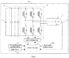
- Fig. 1 is a simplified structural view of an electric drive system 10 for an electric vehicle in an embodiment of the present invention.
- the electric vehicle electric drive system 10 comprises a battery set 1, an accelerator-pedal position sensor 2, an angle sensor 3, a capacitor set 4, a motor controller 5, an inverter 6, a drive isolating unit 7, a motor 8, a rotary transformer 9 and a brake-pedal position sensor 11.
- the battery set 1 may adopt the high power battery set, the voltage of which is 200V ⁇ 330V, and the battery set 1 is the energy for the whole electric drive system.
- the accelerator-pedal position sensor 2 and the brake-pedal position sensor 11 are installed at the places as that for conventional vehicles, for detecting and sending an accelerator-pedal position signal and a brake-pedal position signal to the motor controller 5 respectively.
- the angle sensor 3 is installed on the chassis of the whole vehicle, for detecting and outputting a tilt angle signal to the motor controller 5. In particular, when the motor controller 5 receives the angle signals, firstly smoothing the angle signals to remove the interference in the signals, and then determining whether the vehicle is in downhill mode based on the processed angle signals.
- the positive pole of capacitor set 4 is connected with the positive bus of the battery set 1, and its negative pole is connected with the negative bus of the battery set 1, for absorbing the high frequency surge voltage and smoothing the DC voltage waveform.
- the motor controller 5 is for calculating Pulse Width Modulation (PWM) signals and sending them to the inverter 6 through the drive isolating unit 7.
- the inverter 6 comprises three intelligent power modules (IPM), or such power devices as IGBT and transistor etc,. Each IPM has the upper and lower arm, and the input terminal of upper arms of three IPMs may be connected with the positive bus of the battery set 1, while their lower arms may be connected with the negative bus of the battery set 1. All contacts of IPMs shall be respectively connected with 3-phase coils (i.e.
- the motor 8 is a permanent-magnet synchronous motor, as the power output source of electric vehicle.
- the rotary transformer 9 is for detecting the rotating angle of rotor of motor 8, and sending to the motor controller 5 after a revolving decoding unit (not shown) decoding.
- the rotary transformer 9 and the revolving decoding unit can used as a vehicle speed sensor, and the current vehicle speed V could be calculated according to the positions of the rotor. Certainly, an individual vehicle speed sensor may be used.
- the principle of the present invention is based on calculating the torque T to be outputted to the wheels from the motor in downhill mode according to the equivalent downhill slip torque T 1 due to the gravity in the forward direction of the vehicle and the accelerator-pedal travel value Gain corresponding to the pedal depth stepped by the driver, the current vehicle speed value V and the given vehicle speed delimitative value V ref .
- the motor controller 5 of electric vehicle electrical system 10 may calculate the equivalent downhill slip torque T 1 due to the gravity of the vehicle in the forward direction under the tilt angle value ⁇ according to the detected tilt angle value angle ⁇ of the vehicle from the angle sensor 3, combined with total mass m and the current vehicle speed value V, and obtain the maximum output torque T 2 under the current vehicle speed V (i.e., the torque output by the motor when the accelerator-pedal travel value is maximum). Based on these calculations and according to the accelerator-pedal travel value Gain, the current vehicle speed value V and the given vehicle speed delimitative value V ref , determining the torque addition item, and adding the maximum output torque T 2 of the motor and the downhill slip torque T 1 to acquire the final output torque T of the motor.
- the output torque of the motor may allow for the gravity-equivalent downhill slip torque addition item, and be added with T 1 to obtain the final torque for the wheels.
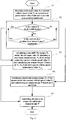
- Fig. 2 it is a flow chart of the method for controlling output torque of a motor according to an embodiment in the present invention, comprises the following steps:
- step S2 the downhill mode may be further conformed based on the current gear position, as the dashed shown in Fig. 2 .
- the detect current gear position is at forward gear position, it illustrates that the vehicle is in downhill mode now.
- the flow of step S2 is executed as indicated by the dashed lines.
- the downhill mode may be determined according to another aspect. That is if the current vehicle speed V is increased but not due to stepping on the accelerator pedal (i.e., the driver does not accelerate actively), and the accelerator-pedal travel value Gain is not increased or the brake-pedal value Brake_Deep is reduced on the contray, the situation also illustrates the vehicle is in downhill mode. This manner can be an assistant embodiment for determining.
- step S2 if it is determined that the vehicle is in downhill mode and the accelerator-pedal travel value Gain is increased, which indicate the driver accelerates actively, then going to step S4 and controlling the output torque based on the actual accelerator-pedal travel value Gain.
- step S3 calculating the downhill slip torque T 1 of the vehicle based on the tilt angle-value ⁇ , the current vehicle speed value V and total mass m of vehicle and obtaining the maximum output torque T 2 of the motor under the current vehicle speed value V.
- the maximum output torque T 2 of the motor depends on the motor external performance curve. Upon different vehicle speeds, the maximum output torques of a motor are different with each other. According to the function relationship between the maximum output torque T 2 and the vehicle speed, upon a specified vehicle speed V, the maximum output torque T 2 of the motor is also a specified value.
- the maximum output torque T 2 of the motor may be founded from the external performance curve of the motor measured through experiments.
- the motor controller 5 will calculate a final output torque T of the motor based on the accelerator-pedal travel value Gain, the current vehicle speed value V, the downhill slip torque T 1 , and the maximum output torque T 2 of motor.
- the vehicle speed may be higher or lower, for high vehicle speed cases, it is expected that the vehicle speed may be not too high, for low vehicle speed case, it is expected that the vehicle speed may be stably increased to a specified given value, so in step S3, the output torque T of motor may be calculated in two states, and the details are shown as Fig. 3 .
- step S32 giving a given vehicle speed delimitative value V ref , and comparing the current vehicle speed value with the given vehicle speed delimitative value V ref , which is a normal running speed, for example 30km/h. If the current vehicle speed value V is greater than the given vehicle speed delimitative value V ref , then going to step S33; or if the current vehicle speed value V is less than or equal to the given vehicle speed delimitative value V ref , then going to step S34.
- the detailed execution method is: as shown in Fig. 5 , defining output torque T as Y-axis and accelerator-pedal travel value Gain as X-axis, and drawing a linear curve 200 with -T 1 as a starting point and the summation T 2 -T 1 of T 2 and -T 1 as a final point.
- the output torque T may be increased linearly with the increasing of accelerator-pedal travel value Gain, when the accelerator-pedal travel value Gain reaches to a maximum value 100%, the correpsonding output torque T also reaches a maximum value T 2 -T 1 .
- the minimum output torque of the motor is -T 1 and the maximum torque of the motor is T 2 -T 1 . While after adding with T 1 , the minimum equivalent torque of wheel itself is 0, and the maximum equivalent torque is T 2 , which may well guarantee the vehicle speed not too high.
- the detailed embodiment is: as shown in Fig. 5 , according to the equivalent torque T 1 due to the gravity in the forward direction, i.e. the downhill slip torque T 1 , defining output torque T as Y-axis and accelerator-pedal travel value Gain as X-axis, and drawing a linear curve 100 with -T 3 as a starting point and the summation T 2 -T 3 of the maximum output torque T 2 of the motor under the current vehicle speed value V and -T 3 as a final point.
- the output torque T may be increased linearly with the increasing of accelerator-pedal travel value Gain, when the accelerator-pedal travel value Gain reaches to a maximum value 100%, the correpsonding output torque T also reaches a maximum value T 2 -T 3 .
- the minimum output torque of the motor is -T 3
- the maximum torque of the motor is T 2 -T 3
- the minimum torque of wheels is T 1 -T 3
- the maximum torque of wheels is T 2 +T 1 -T 3 , i.e. T 2 + 1 ⁇ T V ref ⁇ T 1 .
- the vehicle speed may smoothly rise to the given vehicle speed delimitative value V ref , (for example 30km/h), and when the vehicle speed is beyond the given vehicle speed delimitative value V ref , going to step S33, thereby the vehicle speed in downhill mode will be not too high.
- -T 3 varies from o to -T 1 , and the value is determined by the current vehicle speed value V and the given vehicle speed delimitative value V ref .
- the line 100 in Fig. 5 is corresponding to the output torque line of vehicle under low speed in downhill mode
- the line 200 is corresponding to the output torque line of vehicle under high speed in downhill mode. Since the line 100 is above the line 200, it indicates that under a same accelerator-pedal travel value Gain, the output torque of the motor under low speed is greater than that underhigh speed.
- the vehicle speed may be stably increased to a given value, when it is more than the given value, that is, when the vehicle speed is higher, the output torque of motor is decreased, and even outputting a reverse torque, corresponding to the reverse tractive and brake torque of fuel-fired vehicle engine, so that the vehicle speed will be not too high, and high safety and comfort of vehicle is guaranteed.
- step S5 the motor controller 5 may output corresponding PWM control signals according to the calculated output torque T of the motor, and output to the inverter 6 and the inverter 6 may control the motor to output the corresponding torque.
- the apparatus for realizing the control method mentioned above is shown as Fig. 4 , besides the angle sensor 3, the vehicle speed sensor 12, the accelerator-pedal position sensor 2, and the motor controller 5, further comprising a vehicle speed monitoring unit 43, a driving mode monitoring unit 44, a gear position sensor 41 (optional) and a gear position detecting unit 42 (optional).
- the driving mode monitoring unit 44 is configured to receive the tilt angle signal from the angle sensor 3 and the vehicle speed signal from the vehicle speed sensor 12, obtain the tilt angle value ⁇ and the current vehicle speed value V based on the signals, determine the vehicle is in downhill mode when the tilt angle value ⁇ is negative and the current speed value V is positive, and output a fourth control signal to the vehicle speed monitoring unit 43.
- the vehicle speed monitoring unit 43 is configured to be actived for operating when receiving the fourth control signal.
- the driving mode monitoring unit 44 is further configured the signals from the accelerator-pedal position sensor 2 or the brake-pedal position sensor 11, and the principle of determination is same with that of step S2, which will not be introduced again.
- the gear position sensor 41 is for detecting gear position of the vehicle and outputting a gear position signal to a gear position detecting unit 42.
- the gear position detecting unit 42 is for receiving the gear position signal, obtaining a current gear position based on the gear position signal, determining whether the current gear position is at forward gear, and outputring a third control signal to the vehicle speed monitoring unit 43 if the current gear position is at forward gear.
- the vehicle speed monitoring unit 43 is further configured to be actived for operating when receiving the third control signal and the fourth control signal at the same time.
- the vehicle speed monitoring unit 43 is configured to receive the vehicle speed signal from the vehicle speed sensor 12, obtain the current vehicle speed value V based on the siganl, compare the current vehicle speed value V with the given vehicle speed delimitative value V ref (preferably 30km/h), and output a first control signal to the motor controller 5 if the current vehicle speed value V is greater than the given vehicle speed delimitative value V ref , or output a second control signal to the motor controller 5 if the current vehicle speed value V is less than or equal to the given vehicle speed delimitative value V ref .
- V ref preferably 30km/h
- the motor controller 5 may calculate the required output torque according to the strategy of the invention, and the motor 8 may output the torque to wheels.
- the output torque may enable the vehicle speed not too high, and improve the vehicle safety and driving comfort.
Landscapes
- Engineering & Computer Science (AREA)
- Power Engineering (AREA)
- Transportation (AREA)
- Mechanical Engineering (AREA)
- Electric Propulsion And Braking For Vehicles (AREA)
- Hybrid Electric Vehicles (AREA)
Claims (10)
- Verfahren zum Steuern eines Abtriebsdrehmoments eines Motors (8) für ein elektrisches Fahrzeug in einem Bergabmodus, die folgenden Schritte umfassend:S1) Detektieren eines Neigungswinkelwertes θ, eines momentanen Fahrzeuggeschwindigkeitswerts V und eines Gaspedalwegwerts Gain eines Fahrzeugs, wobei der Wert Gain in dem Bereich von 0% bis 100% ist,S2) Bestimmen, ob das Fahrzeug im Bergabmodus ist oder nicht und falls ja, Übergehen zu Schritt S4;S3) Berechnen eines Bergabschlupfdrehmoments T1 aufgrund der Beschleunigung des Fahrzeugs in der vorwärts Richtung unter dem Neigungswinkelwert θ, Erhalten eines maximalen Abtriebsdrehmoments T2 des Motors bei dem momentanen Geschwindigkeitswert V, Berechnen eines Abtriebsdrehmoments T des Motors basierend auf dem Bergabschlupfdrehmoment T1, dem maximalen Abtriebsdrehmoments T2 des Motors bei dem momentanen Geschwindigkeitswert V, dem Gaspedalwegwert Gain und einem gegebenen Geschwindigkeitsbegrenzungswert Vref und Übergehen zu Schritt S5;S4) Erhalten eines maximalen Abtriebsdrehmoments T2 des Motors bei dem momentanen Geschwindigkeitswert V, Berechnen eines Abtriebsdrehmoments des Motors basierend auf dem maximalen Abtriebsdrehmoments T2 bei dem Momentanen Geschwindigkeitswert V und dem Gaspedalwegwert Gain und Übergehen zu Schritt S5; undS5) Steuern des Motors, das berechnete Abtriebsdrehmoment T anzulegen; in Schritt S3 ferner Vergleichen des momentanen Fahrzeuggeschwindigkeitswert V mit dem gegebenen Geschwindigkeitsbegrenzungswert Vref und Berechnen des Abtriebsdrehmoments T des Motors entsprechend dem Ergebnis eines Vergleichs und der folgenden Gleichung:

- Verfahren nach Anspruch 1, wobei in Schritt S3 das Bergabschlupfdrehmoment T1 entsprechend der folgenden Gleichung berechnet wird:

- Verfahren nach Anspruch 1 oder 2, wobei der gegebene Fahrzeuggeschwindigkeitsbegrenzungswert Vref 30km/h ist.
- Verfahren nach Anspruch 1, wobei in Schritt S2 bestimmt wird, dass das Fahrzeug im Bergabmodus ist, wenn der Neigungswinkelwert θ negativ und der momentane Fahrzeuggeschwindigkeitswert V positiv ist.
- Verfahren nach einem der Ansprüche 1 oder 4, wobei in Schritt S1 ferner eine momentane Gangposition des Fahrzeugs detektiert wird und in schritt S2, neben einem Bestimmen ob das Fahrzeug in dem Bergabmodus ist oder nicht, ferner bestimmt wird, ob die momentane Gangposition ein Vorwärtsgang ist oder nicht und falls das Fahrzeug in dem Bergabmodus ist und die momentane Gangposition ein Vorwärtsgang ist, Übergehen zu Schritt S3 andernfalls Übergehen zu Schritt S4.
- Vorrichtung zum Steuern eines Abtriebsdrehmoments eines Motors (8) für ein elektrisches Fahrzeug in einem Bergabmodus, umfassend:einen Winkelsensor (3) zum Bestimmen eines Neigungswinkels des Fahrzeugs und Ausgeben eines Neigungswinkelsignals an eine Motorsteuerung (5);einen Fahrzeuggeschwindigkeitssensor (12) zum Detektieren einer momentanen Geschwindigkeit des Fahrzeugs und Ausgeben eines Fahrzeuggeschwindigkeitssignals an die Motorsteuerung (5);einen Gaspedalpositionssensor (2) zum Bestimmen einer Position des Gaspedals und Ausgeben eines Gaspedalpositionssignals an die Motorsteuerung (5);wobei die Motorsteuerung (5) dazu ausgestaltet ist:das Neigungswinkelsignal, das Fahrzeuggeschwindigkeitssignal und das Gaspedalpositionssignal zu empfangen, einen Neigungswinkelwert θ, einen momentanen Fahrzeuggeschwindigkeitswert V und einen Gaspedalwegwert Gain für das Fahrzeug basierend auf den Signalen, wobei der Wert Gain in dem Bereich von 0% - 100% ist, zu erhalten, zu bestimmen ob das Fahrzeug in dem Bergabmodus ist oder nicht:falls das Fahrzeug in dem Bergabmodus ist, dann ein Bergabschlupfdrehmoment T1 des Fahrzeugs bei dem Neigungswinkelwert θ zu berechnen, ein maximales Abtriebsdrehmoment T2 des Motors bei dem momentanen Fahrzeuggeschwindigkeitswert V zu erhalten, ein Abtriebsdrehmoment T basierend auf dem Bergabschlupfdrehmoment T1 aufgrund der Beschleunigung des Fahrzeugs in der Vorwärtsrichtung unter dem Neigungswinkelwert θ, dem maximalen Abtriebsdrehmoment T2, dem Gaspedalwegwert Gain und einem gegebenen Fahrzeuggeschwindigkeitsbegrenzungswert Vref zu berechnen; oder wenn das Fahrzeug nicht in dem Bergabmodus ist, ein maximales Abtriebsdrehmoment T2 des Motors bei dem momentanen Fahrzeuggeschwindigkeitswert V zu erhalten, ein Abtriebsdrehmoment T basierend auf dem maximalen Abtriebsdrehmoment T2 des Motors und dem Gaspedalwegwerts Gain zu berechnen; undein Steuerungssignal zum Steuern des Motors zu generieren, das berechnete Abtriebsdrehmoment T anzulegen, dadurch gekennzeichnet, dass die Vorrichtung ferner umfasst, eine Fahrzeuggeschwindigkeitsüberwachungseinheit (43) und der Fahrzeuggeschwindigkeitssensor (12) ferner das Fahrzeuggeschwindigkeitssignal an die Fahrzeuggeschwindigkeitsüberwachungseinheit (43) überträgt, die dazu ausgestaltet ist, das Fahrzeuggeschwindigkeitssignal zu empfangen, den momentanen Fahrzeuggeschwindigkeitswert V basierend auf dem Signal zu erhalten, den momentanen Fahrzeuggeschwindigkeitswerts mit einem gegebenen Fahrzeuggeschwindigkeitsbegrenzungswert Vref zu vergleichen und ein erstes Steuerungssignal an die Motorsteuerung (5) auszugeben, falls der momentane Fahrzeuggeschwindigkeitswert V größer als der Fahrzeuggeschwindigkeitsbegrenzungswert Vref ist oder ein zweites Steuerungssignal an die Motorsteuerung (5) auszugeben, falls der momentane Fahrzeuggeschwindigkeitswert V kleiner oder gleich dem Fahrzeuggeschwindigkeitsbegrenzungswert Vref ist; und wobeidie Motorsteuerung (5) ferner ausgestaltet ist, in einem Fall, in dem bestimmt wird, dass das Fahrzeug in dem Bergabmodus ist, das Abtriebsdrehmoment T des Motors entsprechend der Gleichung T = - T1 + T2 x Gain zu berechnen, wenn das erste Steuerungssignal empfangen wird, und das Abtriebsdrehmoment entsprechend der Gleichung T = -T3 + T2 x Gain zu berechnen, wenn das zweite Steuerungssignal empfangen wird, wobei

- Vorrichtung nach Anspruch 6, wobei die Motorsteuerung (5) ferner ausgestaltet ist, das Bergabschlupfdrehmoment T1 entsprechend der folgenden Gleichung zu berechnen:

- Vorrichtung nach Anspruch 6 oder 7, wobei der gegebene Fahrzeuggeschwindigkeitsbegrenzungswert Vref 30km/h ist.
- Vorrichtung nach Anspruch 6 oder 7, ferner umfassend, eine Fahrmodusüberwachungseinheit (44) und den Winkelsensor und den Fahrzeuggeschwindigkeitssensor (12), die das Neigungswinkelsignal und das Fahrzeuggeschwindigkeitssignal zu der Fahrmodusüberwachungseinheit (44) jeweils ausgeben, die dazu ausgestaltet ist, das Neigungswinkelsignal und das Fahrzeuggeschwindigkeitssignal zu empfangen, den Neigungswinkelwert θ und den momentanen Fahrzeuggeschwindigkeitswert V basierend auf den Signalen zu erhalten, zu bestimmen, dass das Fahrzeug in dem Bergabmodus ist, wenn der Neigungswinkel θ negativ und der momentane Fahrzeuggeschwindigkeitswert V positiv ist, und ein viertes Steuerungssignal an die Fahrzeuggeschwindigkeitsüberwachungseinheit (43) auszugeben; und wobei
die Fahrzeuggeschwindigkeitsüberwachungseinheit (43) ferner ausgestaltet ist, für eine Betätigung aktiviert zu sein, wenn das vierte Steuerungssignal empfangen wird. - Vorrichtung nach Anspruch 9, ferner umfassend:einen Gangpositionssensor (41) zum Detektieren einer Gangposition des Fahrzeugs und Ausgeben eines Gangpositionssignals an eine Gangpositionsdetektionseinheit (42); undwobei die Gangpositionsdetektionseinheit zum Empfangen des Gangpositionssignals einen momentanen Gangpositionswert basierend auf dem Gangpositionssignal erhält, bestimmt, ob die momentane Gangposition ein Vorwärtsgang ist und ein drittes Steuerungssignal an die Fahrzeuggeschwindigkeitsüberwachungseinheit (43) ausgibt, falls die Gangposition ein Vorwärtsgang ist; und wobeidie Fahrzeuggeschwindigkeitsüberwachungseinheit (43) ferner ausgestaltet ist, für eine Betätigung aktiviert zu sein, wenn das dritte Steuerungssignal und das vierte Steuerungssignal gleichzeitig empfangen werden.
Applications Claiming Priority (2)
| Application Number | Priority Date | Filing Date | Title |
|---|---|---|---|
| CN2006101577312A CN101209681B (zh) | 2006-12-26 | 2006-12-26 | 电动汽车下坡状态下电机输出转矩控制系统及控制方法 |
| PCT/CN2007/071334 WO2008077351A1 (en) | 2006-12-26 | 2007-12-26 | Method and apparatus for controlling output torque of a motor for an electric vehicle in downhill mode |
Publications (3)
| Publication Number | Publication Date |
|---|---|
| EP2099641A1 EP2099641A1 (de) | 2009-09-16 |
| EP2099641A4 EP2099641A4 (de) | 2013-07-17 |
| EP2099641B1 true EP2099641B1 (de) | 2016-05-11 |
Family
ID=39562109
Family Applications (1)
| Application Number | Title | Priority Date | Filing Date |
|---|---|---|---|
| EP07846160.5A Active EP2099641B1 (de) | 2006-12-26 | 2007-12-26 | Verfahren und vorrichtung zur steuerung des ausgangsdrehmoments eines motors für ein elektrofahrzeug im gefällemodus |
Country Status (4)
| Country | Link |
|---|---|
| US (1) | US8326510B2 (de) |
| EP (1) | EP2099641B1 (de) |
| CN (1) | CN101209681B (de) |
| WO (1) | WO2008077351A1 (de) |
Cited By (1)
| Publication number | Priority date | Publication date | Assignee | Title |
|---|---|---|---|---|
| CN106427600A (zh) * | 2015-08-07 | 2017-02-22 | 舍弗勒技术股份两合公司 | 一种用于电驱动汽车的下坡辅助驾驶装置及控制方法 |
Families Citing this family (59)
| Publication number | Priority date | Publication date | Assignee | Title |
|---|---|---|---|---|
| CN101209682B (zh) * | 2006-12-26 | 2010-09-29 | 比亚迪股份有限公司 | 电动汽车爬坡状态下电机输出转矩控制系统及控制方法 |
| CN101209681B (zh) * | 2006-12-26 | 2010-09-29 | 比亚迪股份有限公司 | 电动汽车下坡状态下电机输出转矩控制系统及控制方法 |
| US8065050B2 (en) * | 2008-04-25 | 2011-11-22 | GM Global Technology Operations LLC | Method and apparatus for detecting an insufficient phase current in a permanent magnet synchronous motor |
| US8401753B2 (en) * | 2009-11-23 | 2013-03-19 | Caterpillar Inc. | Automatic downhill speed control system |
| TWI396641B (zh) * | 2010-09-27 | 2013-05-21 | Kwang Yang Motor Co | Automatic deceleration control device and method for electric scooter |
| IT1402994B1 (it) * | 2010-11-12 | 2013-09-27 | Campagnolo Tullio | Sistema di regolazione della velocita' di un veicolo |
| DE112011105812B4 (de) * | 2011-11-04 | 2021-12-16 | Toyota Jidosha Kabushiki Kaisha | Fahrzeug und Fahrzeugsteuerungsverfahren |
| JP6027380B2 (ja) * | 2012-09-28 | 2016-11-16 | 富士重工業株式会社 | 電気自動車の駆動装置 |
| CN103029596B (zh) * | 2012-10-30 | 2015-07-08 | 荣成华泰汽车有限公司 | 电动汽车蠕动控制方法、装置及电动汽车 |
| DE112013005524T5 (de) | 2012-12-07 | 2015-07-30 | Kelsey-Hayes Company | Fahrzeuggeschwindigkeitssteuerungssystem |
| WO2014113797A1 (en) * | 2013-01-18 | 2014-07-24 | Brammo, Inc. | Method and apparatus for preventing over-shifting on electric vehicles |
| CN103196611B (zh) * | 2013-03-26 | 2014-09-24 | 中国科学院自动化研究所 | 无人动力三角翼操纵力测量装置及其标定方法 |
| DE102014202227A1 (de) * | 2014-02-07 | 2015-08-13 | Zf Friedrichshafen Ag | Verfahren zum Ansteuern eines Zwei-Gang-Getriebes mit elektrischer Maschine |
| US20160090005A1 (en) * | 2014-03-10 | 2016-03-31 | Dean Drako | Distributed Torque Generation System and Method of Control |
| US20160236589A1 (en) * | 2014-03-10 | 2016-08-18 | Shivinder Singh Sikand | Four motor propulsion system and yaw vectoring control circuit |
| GB2526143B (en) * | 2014-05-16 | 2018-02-28 | Jaguar Land Rover Ltd | Vehicle speed control system and method |
| CN104827931B (zh) * | 2014-07-29 | 2017-02-08 | 北汽福田汽车股份有限公司 | 电动汽车工作模式的控制方法、系统及具有其的电动汽车 |
| JP6374795B2 (ja) * | 2015-01-06 | 2018-08-15 | 東洋電機製造株式会社 | 車両制御装置 |
| KR20160090524A (ko) * | 2015-01-22 | 2016-08-01 | 엘지전자 주식회사 | 전기 자동차 및 전기 자동차의 제어 방법 |
| JP6060195B2 (ja) * | 2015-03-06 | 2017-01-11 | 本田技研工業株式会社 | 車両駐車制御装置 |
| CN105034853B (zh) * | 2015-07-31 | 2017-07-11 | 深圳巴斯巴科技发展有限公司 | 一种减小电动汽车定速巡航速度波动的控制系统及方法 |
| MX2018004072A (es) * | 2015-10-27 | 2018-08-01 | Ford Global Tech Llc | Notificacion mejorada de sistema de vehiculo. |
| CA3004537A1 (en) * | 2015-11-09 | 2017-05-18 | Nissan Motor Co., Ltd. | Braking/driving force control method and braking/driving force control device |
| US10232840B2 (en) * | 2016-08-08 | 2019-03-19 | Ford Global Technologies, Llc | Deceleration control for a hybrid vehicle during towing |
| CN106394254B (zh) * | 2016-12-05 | 2019-05-28 | 潍柴动力股份有限公司 | 一种应用于电动汽车的陡坡缓降方法和装置 |
| CN106809055B (zh) * | 2017-01-22 | 2019-12-10 | 北京新能源汽车股份有限公司 | 一种电机输出扭矩控制方法及装置 |
| US10131354B1 (en) | 2017-05-16 | 2018-11-20 | Ford Global Technologies, Llc | Engine speed stabilization |
| CN107253451B (zh) * | 2017-06-28 | 2019-09-03 | 北京新能源汽车股份有限公司 | 下坡时电动汽车定速巡航加速控制方法、装置及系统 |
| US10618512B2 (en) * | 2017-08-04 | 2020-04-14 | Toyota Motor Engineering & Manufacturing North America, Inc. | Expanding electric vehicle mode during downhill grade conditions |
| CN107884199B (zh) * | 2017-12-01 | 2023-08-29 | 西华大学 | 一种自带倒拖功能的单缸发动机台架实验系统及其控制方法 |
| WO2019126966A1 (zh) * | 2017-12-25 | 2019-07-04 | 深圳配天智能技术研究院有限公司 | 机动车及其扭矩控制方法 |
| CN108189708B (zh) * | 2017-12-28 | 2022-02-01 | 深圳市布谷鸟科技有限公司 | 一种联合控制电动汽车电机的方法 |
| CN110466521A (zh) * | 2018-05-11 | 2019-11-19 | 奥迪股份公司 | 驾驶辅助系统和方法 |
| CN109815598B (zh) * | 2019-01-28 | 2023-06-23 | 重庆瑜欣平瑞电子股份有限公司 | 一种增强电动汽车控制系统中电机对油门响应速度算法 |
| CN111634193B (zh) * | 2019-03-01 | 2024-05-14 | 广汽埃安新能源汽车有限公司 | 扭矩方向判断方法、装置、车辆、计算机设备和存储介质 |
| EP3972881B1 (de) * | 2019-05-21 | 2024-10-23 | Volvo Truck Corporation | Verfahren zur steuerung des bremsens eines fahrzeugs |
| CN110303901B (zh) * | 2019-07-12 | 2022-06-14 | 重庆长安新能源汽车科技有限公司 | 一种汽车坡道辅助制动方法、装置及电动汽车 |
| CN112776611A (zh) * | 2019-11-07 | 2021-05-11 | 纳恩博(常州)科技有限公司 | 控制车辆的方法、车辆及介质 |
| CN111993903A (zh) * | 2020-08-24 | 2020-11-27 | 奇瑞商用车(安徽)有限公司 | 一种汽车陡坡缓降控制方法和系统 |
| WO2022048611A1 (en) * | 2020-09-02 | 2022-03-10 | Shanghai United Imaging Healthcare Co., Ltd. | Mobile medical device |
| CN112757908B (zh) * | 2021-01-07 | 2022-11-15 | 东风柳州汽车有限公司 | 爬坡安全性优化方法、装置、设备及存储介质 |
| CN112810456B (zh) * | 2021-01-22 | 2022-10-14 | 北京国家新能源汽车技术创新中心有限公司 | 电动汽车防溜坡控制方法、系统及电动汽车 |
| CN113085563B (zh) * | 2021-04-21 | 2023-04-07 | 中国第一汽车股份有限公司 | 一种电动车辆的缓速制动方法及装置 |
| CN113085572B (zh) * | 2021-04-22 | 2022-11-22 | 浙江吉利控股集团有限公司 | 一种电机扭矩控制方法、控制系统及车辆 |
| CN113232520B (zh) * | 2021-06-18 | 2023-12-19 | 江苏英拓动力科技有限公司 | 一种用于电动车的下坡滑行速度控制方法及下坡滑行速度控制系统 |
| CN113276684B (zh) * | 2021-06-30 | 2022-05-20 | 江铃汽车股份有限公司 | 一种电动汽车滑行能量回收控制方法 |
| CN113844276B (zh) * | 2021-08-31 | 2023-11-17 | 江铃汽车股份有限公司 | 一种坡道起步控制方法、装置、可读存储介质及车辆 |
| CN114148181B (zh) * | 2021-11-26 | 2024-02-02 | 天津英捷利汽车技术有限责任公司 | 基于转速环加位置环的纯电动汽车防溜坡方法及系统 |
| CN114211970B (zh) * | 2021-12-17 | 2024-01-30 | 上海集度汽车有限公司 | 一种能量回收方法、设备、车辆及存储介质 |
| CN114056125B (zh) * | 2021-12-24 | 2023-12-26 | 天津英捷利汽车技术有限责任公司 | 一种纯电动汽车的下坡限速保护方法 |
| CN114633634B (zh) * | 2022-02-24 | 2023-08-18 | 一汽解放汽车有限公司 | 电机摘档控制方法、装置、计算机设备和存储介质 |
| CN114987225B (zh) * | 2022-07-22 | 2025-09-26 | 奇瑞新能源汽车股份有限公司 | 基于坡度传感器的新能源汽车电制动和停车方法及系统 |
| CN115520025B (zh) * | 2022-09-21 | 2025-07-25 | 福建晋工新能源科技有限公司 | 扭矩控制方法、装置、终端设备以及存储介质 |
| CN115648964B (zh) * | 2022-10-28 | 2025-07-22 | 智新科技股份有限公司 | 基于电机控制器的电动汽车防溜坡控制方法及系统 |
| CN115782622B (zh) * | 2022-12-09 | 2024-12-17 | 浙江中车电车有限公司 | 一种车辆的双轴驱动控制方法 |
| CN115871468B (zh) * | 2023-02-02 | 2023-05-30 | 临工重机股份有限公司 | 工程车辆控制方法、装置、车辆及存储介质 |
| US12617290B2 (en) * | 2023-05-30 | 2026-05-05 | Cummins Inc. | Dynamic vehicle speed control |
| CN119682552B (zh) * | 2023-09-22 | 2025-12-02 | 浙江春风动力股份有限公司 | 电动全地形车 |
| CN119261587B (zh) * | 2024-12-11 | 2025-04-01 | 山西天地煤机装备有限公司 | 六驱框架式蓄电池车多点驱动模式自适应切换方法和系统 |
Family Cites Families (22)
| Publication number | Priority date | Publication date | Assignee | Title |
|---|---|---|---|---|
| US5457363A (en) * | 1993-02-09 | 1995-10-10 | Toyota Jidosha Kabushiki Kaisha | Driving-force regulating apparatus for electric vehicle |
| US5793175A (en) * | 1995-01-19 | 1998-08-11 | Textron Inc. | Performance event sensing for control of electric motor driven golf car |
| FR2756521B1 (fr) * | 1996-11-29 | 1999-01-08 | Renault | Procede de regulation de la vitesse d'un vehicule electrique en descente |
| WO1998041417A1 (en) * | 1997-03-19 | 1998-09-24 | Hitachi, Ltd. | Method for controlling electric rolling stock |
| JP3542255B2 (ja) | 1997-10-06 | 2004-07-14 | 株式会社日立製作所 | 電気自動車 |
| JP2001025109A (ja) * | 1999-07-05 | 2001-01-26 | Mitsubishi Motors Corp | 電気自動車のモータトルク制御装置 |
| US20040020695A1 (en) | 2002-08-05 | 2004-02-05 | Ford Motor Company | Apparatus and a method for determining hybrid-electric vehicle performance |
| KR20040028374A (ko) * | 2002-09-30 | 2004-04-03 | 현대자동차주식회사 | 전기 자동차의 슬립 제거장치 및 방법 |
| JP4239724B2 (ja) * | 2003-07-29 | 2009-03-18 | トヨタ自動車株式会社 | 車両および車両の制御方法 |
| JP4503317B2 (ja) * | 2004-03-10 | 2010-07-14 | 株式会社リコー | 光走査装置、画像形成装置 |
| JP2006094589A (ja) * | 2004-09-21 | 2006-04-06 | Toyota Motor Corp | 車両の減速度制御装置 |
| CN100400333C (zh) * | 2004-11-19 | 2008-07-09 | 丰田自动车株式会社 | 汽车及其控制方法 |
| JP4655723B2 (ja) | 2005-03-31 | 2011-03-23 | トヨタ自動車株式会社 | 車両およびその制御方法 |
| CN101351355B (zh) * | 2005-12-26 | 2010-11-10 | 丰田自动车株式会社 | 车辆控制器、车辆与车辆控制方法 |
| RU2390679C2 (ru) * | 2005-12-26 | 2010-05-27 | Комацу Лтд. | Строительное транспортное средство |
| CN101209682B (zh) * | 2006-12-26 | 2010-09-29 | 比亚迪股份有限公司 | 电动汽车爬坡状态下电机输出转矩控制系统及控制方法 |
| CN101209681B (zh) * | 2006-12-26 | 2010-09-29 | 比亚迪股份有限公司 | 电动汽车下坡状态下电机输出转矩控制系统及控制方法 |
| JP4458300B2 (ja) * | 2007-10-25 | 2010-04-28 | 本田技研工業株式会社 | 電動車両、および電動車両の回生制御方法 |
| JP5346483B2 (ja) * | 2008-04-14 | 2013-11-20 | ヤンマー株式会社 | 作業車両 |
| EP2138367B1 (de) * | 2008-06-26 | 2015-05-13 | Kawasaki Jukogyo Kabushiki Kaisha | Schlupfregelsystem für Fahrzeug |
| EP2138365B1 (de) * | 2008-06-26 | 2015-05-06 | Kawasaki Jukogyo Kabushiki Kaisha | Schlupfregelsystem für Kraftfahrzeug |
| EP2138368B1 (de) * | 2008-06-26 | 2013-03-20 | Kawasaki Jukogyo Kabushiki Kaisha | Schlupfregelsystem für Fahrzeug |
-
2006
- 2006-12-26 CN CN2006101577312A patent/CN101209681B/zh active Active
-
2007
- 2007-12-26 WO PCT/CN2007/071334 patent/WO2008077351A1/en not_active Ceased
- 2007-12-26 US US12/521,032 patent/US8326510B2/en active Active
- 2007-12-26 EP EP07846160.5A patent/EP2099641B1/de active Active
Cited By (1)
| Publication number | Priority date | Publication date | Assignee | Title |
|---|---|---|---|---|
| CN106427600A (zh) * | 2015-08-07 | 2017-02-22 | 舍弗勒技术股份两合公司 | 一种用于电驱动汽车的下坡辅助驾驶装置及控制方法 |
Also Published As
| Publication number | Publication date |
|---|---|
| US8326510B2 (en) | 2012-12-04 |
| EP2099641A1 (de) | 2009-09-16 |
| CN101209681A (zh) | 2008-07-02 |
| CN101209681B (zh) | 2010-09-29 |
| EP2099641A4 (de) | 2013-07-17 |
| WO2008077351A1 (en) | 2008-07-03 |
| US20100004808A1 (en) | 2010-01-07 |
Similar Documents
| Publication | Publication Date | Title |
|---|---|---|
| US8326510B2 (en) | Method and apparatus for controlling output torque of a motor for an electric vehicle in downhill mode | |
| EP2097291B1 (de) | Verfahren und vorrichtung zur steuerung des ausgangsdrehmoments eines motors für ein elektrofahrzeug im steigungsmodus | |
| EP2097288B1 (de) | Vorrichtung und verfahren zur steuerung des energierückflusses für ein elektrofahrzeug | |
| US10300795B2 (en) | Regenerative braking control device of electric vehicle | |
| US8892281B2 (en) | Torque control system for suppressing vibration in an electric vehicle | |
| KR100993301B1 (ko) | 차량의 제어 장치 및 제어 방법 | |
| US9321370B2 (en) | Control method of electric vehicle | |
| US8214096B2 (en) | Apparatus and method for controlling an accelerator for electric vehicles | |
| US7189177B2 (en) | Electrically operated vehicle drive controller, electrically operated vehicle drive control method, and electrically operated vehicle with a vehicle drive controller | |
| US10029678B2 (en) | Drive control device with traction control function for right-left independent drive vehicle | |
| US11130498B2 (en) | Motor vehicle | |
| CN103043056A (zh) | 控制车轮轴扭矩的方法和用于其的控制系统 | |
| CN102673377A (zh) | 混合动力车辆的控制装置 | |
| KR102529518B1 (ko) | 친환경자동차의 구동 토크 지령 생성 장치 및 방법 | |
| KR20150025920A (ko) | 친환경 차량의 모터 시스템 제어 장치 및 방법 | |
| CN105711442A (zh) | 使用永磁同步电动机驱动控制系统的坡道辅助控制方法 | |
| CN101659219B (zh) | 汽车上坡状态下电机输出转矩控制系统及控制方法 | |
| KR100579925B1 (ko) | 4륜 하이브리드 전기자동차의 슬립 제어장치 및 방법 | |
| KR102135860B1 (ko) | 전력 기반 자동차의 경사로 속도 제한 방법 | |
| JP2000104590A (ja) | ハイブリッド車両 | |
| JP3933149B2 (ja) | 車両の駆動力制御装置 | |
| CN119459354A (zh) | 一种电动汽车坡道辅助驾驶的控制系统及控制方法 | |
| JP2010126045A (ja) | 車両の駆動力制御装置及びその方法 |
Legal Events
| Date | Code | Title | Description |
|---|---|---|---|
| PUAI | Public reference made under article 153(3) epc to a published international application that has entered the european phase |
Free format text: ORIGINAL CODE: 0009012 |
|
| 17P | Request for examination filed |
Effective date: 20090617 |
|
| AK | Designated contracting states |
Kind code of ref document: A1 Designated state(s): AT BE BG CH CY CZ DE DK EE ES FI FR GB GR HU IE IS IT LI LT LU LV MC MT NL PL PT RO SE SI SK TR |
|
| DAX | Request for extension of the european patent (deleted) | ||
| A4 | Supplementary search report drawn up and despatched |
Effective date: 20130619 |
|
| RIC1 | Information provided on ipc code assigned before grant |
Ipc: B60L 3/08 20060101ALI20130613BHEP Ipc: B60L 15/20 20060101AFI20130613BHEP Ipc: B60L 7/18 20060101ALI20130613BHEP |
|
| 17Q | First examination report despatched |
Effective date: 20130711 |
|
| GRAP | Despatch of communication of intention to grant a patent |
Free format text: ORIGINAL CODE: EPIDOSNIGR1 |
|
| INTG | Intention to grant announced |
Effective date: 20151120 |
|
| GRAS | Grant fee paid |
Free format text: ORIGINAL CODE: EPIDOSNIGR3 |
|
| GRAA | (expected) grant |
Free format text: ORIGINAL CODE: 0009210 |
|
| AK | Designated contracting states |
Kind code of ref document: B1 Designated state(s): AT BE BG CH CY CZ DE DK EE ES FI FR GB GR HU IE IS IT LI LT LU LV MC MT NL PL PT RO SE SI SK TR |
|
| REG | Reference to a national code |
Ref country code: GB Ref legal event code: FG4D |
|
| REG | Reference to a national code |
Ref country code: CH Ref legal event code: EP |
|
| REG | Reference to a national code |
Ref country code: AT Ref legal event code: REF Ref document number: 798361 Country of ref document: AT Kind code of ref document: T Effective date: 20160515 |
|
| REG | Reference to a national code |
Ref country code: IE Ref legal event code: FG4D |
|
| REG | Reference to a national code |
Ref country code: DE Ref legal event code: R096 Ref document number: 602007046303 Country of ref document: DE |
|
| REG | Reference to a national code |
Ref country code: NL Ref legal event code: FP |
|
| REG | Reference to a national code |
Ref country code: LT Ref legal event code: MG4D |
|
| PG25 | Lapsed in a contracting state [announced via postgrant information from national office to epo] |
Ref country code: FI Free format text: LAPSE BECAUSE OF FAILURE TO SUBMIT A TRANSLATION OF THE DESCRIPTION OR TO PAY THE FEE WITHIN THE PRESCRIBED TIME-LIMIT Effective date: 20160511 Ref country code: LT Free format text: LAPSE BECAUSE OF FAILURE TO SUBMIT A TRANSLATION OF THE DESCRIPTION OR TO PAY THE FEE WITHIN THE PRESCRIBED TIME-LIMIT Effective date: 20160511 |
|
| REG | Reference to a national code |
Ref country code: AT Ref legal event code: MK05 Ref document number: 798361 Country of ref document: AT Kind code of ref document: T Effective date: 20160511 |
|
| PG25 | Lapsed in a contracting state [announced via postgrant information from national office to epo] |
Ref country code: ES Free format text: LAPSE BECAUSE OF FAILURE TO SUBMIT A TRANSLATION OF THE DESCRIPTION OR TO PAY THE FEE WITHIN THE PRESCRIBED TIME-LIMIT Effective date: 20160511 Ref country code: SE Free format text: LAPSE BECAUSE OF FAILURE TO SUBMIT A TRANSLATION OF THE DESCRIPTION OR TO PAY THE FEE WITHIN THE PRESCRIBED TIME-LIMIT Effective date: 20160511 Ref country code: GR Free format text: LAPSE BECAUSE OF FAILURE TO SUBMIT A TRANSLATION OF THE DESCRIPTION OR TO PAY THE FEE WITHIN THE PRESCRIBED TIME-LIMIT Effective date: 20160812 Ref country code: PT Free format text: LAPSE BECAUSE OF FAILURE TO SUBMIT A TRANSLATION OF THE DESCRIPTION OR TO PAY THE FEE WITHIN THE PRESCRIBED TIME-LIMIT Effective date: 20160912 Ref country code: LV Free format text: LAPSE BECAUSE OF FAILURE TO SUBMIT A TRANSLATION OF THE DESCRIPTION OR TO PAY THE FEE WITHIN THE PRESCRIBED TIME-LIMIT Effective date: 20160511 |
|
| REG | Reference to a national code |
Ref country code: FR Ref legal event code: PLFP Year of fee payment: 10 |
|
| PG25 | Lapsed in a contracting state [announced via postgrant information from national office to epo] |
Ref country code: IT Free format text: LAPSE BECAUSE OF FAILURE TO SUBMIT A TRANSLATION OF THE DESCRIPTION OR TO PAY THE FEE WITHIN THE PRESCRIBED TIME-LIMIT Effective date: 20160511 |
|
| PG25 | Lapsed in a contracting state [announced via postgrant information from national office to epo] |
Ref country code: DK Free format text: LAPSE BECAUSE OF FAILURE TO SUBMIT A TRANSLATION OF THE DESCRIPTION OR TO PAY THE FEE WITHIN THE PRESCRIBED TIME-LIMIT Effective date: 20160511 Ref country code: EE Free format text: LAPSE BECAUSE OF FAILURE TO SUBMIT A TRANSLATION OF THE DESCRIPTION OR TO PAY THE FEE WITHIN THE PRESCRIBED TIME-LIMIT Effective date: 20160511 Ref country code: CZ Free format text: LAPSE BECAUSE OF FAILURE TO SUBMIT A TRANSLATION OF THE DESCRIPTION OR TO PAY THE FEE WITHIN THE PRESCRIBED TIME-LIMIT Effective date: 20160511 Ref country code: RO Free format text: LAPSE BECAUSE OF FAILURE TO SUBMIT A TRANSLATION OF THE DESCRIPTION OR TO PAY THE FEE WITHIN THE PRESCRIBED TIME-LIMIT Effective date: 20160511 Ref country code: SK Free format text: LAPSE BECAUSE OF FAILURE TO SUBMIT A TRANSLATION OF THE DESCRIPTION OR TO PAY THE FEE WITHIN THE PRESCRIBED TIME-LIMIT Effective date: 20160511 |
|
| REG | Reference to a national code |
Ref country code: DE Ref legal event code: R097 Ref document number: 602007046303 Country of ref document: DE |
|
| PG25 | Lapsed in a contracting state [announced via postgrant information from national office to epo] |
Ref country code: AT Free format text: LAPSE BECAUSE OF FAILURE TO SUBMIT A TRANSLATION OF THE DESCRIPTION OR TO PAY THE FEE WITHIN THE PRESCRIBED TIME-LIMIT Effective date: 20160511 Ref country code: BE Free format text: LAPSE BECAUSE OF FAILURE TO SUBMIT A TRANSLATION OF THE DESCRIPTION OR TO PAY THE FEE WITHIN THE PRESCRIBED TIME-LIMIT Effective date: 20160511 Ref country code: PL Free format text: LAPSE BECAUSE OF FAILURE TO SUBMIT A TRANSLATION OF THE DESCRIPTION OR TO PAY THE FEE WITHIN THE PRESCRIBED TIME-LIMIT Effective date: 20160511 |
|
| PLBE | No opposition filed within time limit |
Free format text: ORIGINAL CODE: 0009261 |
|
| STAA | Information on the status of an ep patent application or granted ep patent |
Free format text: STATUS: NO OPPOSITION FILED WITHIN TIME LIMIT |
|
| 26N | No opposition filed |
Effective date: 20170214 |
|
| PG25 | Lapsed in a contracting state [announced via postgrant information from national office to epo] |
Ref country code: SI Free format text: LAPSE BECAUSE OF FAILURE TO SUBMIT A TRANSLATION OF THE DESCRIPTION OR TO PAY THE FEE WITHIN THE PRESCRIBED TIME-LIMIT Effective date: 20160511 |
|
| PG25 | Lapsed in a contracting state [announced via postgrant information from national office to epo] |
Ref country code: MC Free format text: LAPSE BECAUSE OF FAILURE TO SUBMIT A TRANSLATION OF THE DESCRIPTION OR TO PAY THE FEE WITHIN THE PRESCRIBED TIME-LIMIT Effective date: 20160511 |
|
| REG | Reference to a national code |
Ref country code: CH Ref legal event code: PL |
|
| REG | Reference to a national code |
Ref country code: IE Ref legal event code: MM4A |
|
| PG25 | Lapsed in a contracting state [announced via postgrant information from national office to epo] |
Ref country code: CH Free format text: LAPSE BECAUSE OF NON-PAYMENT OF DUE FEES Effective date: 20161231 Ref country code: LU Free format text: LAPSE BECAUSE OF NON-PAYMENT OF DUE FEES Effective date: 20161226 Ref country code: LI Free format text: LAPSE BECAUSE OF NON-PAYMENT OF DUE FEES Effective date: 20161231 |
|
| PG25 | Lapsed in a contracting state [announced via postgrant information from national office to epo] |
Ref country code: IE Free format text: LAPSE BECAUSE OF NON-PAYMENT OF DUE FEES Effective date: 20161226 |
|
| REG | Reference to a national code |
Ref country code: FR Ref legal event code: PLFP Year of fee payment: 11 |
|
| PG25 | Lapsed in a contracting state [announced via postgrant information from national office to epo] |
Ref country code: CY Free format text: LAPSE BECAUSE OF FAILURE TO SUBMIT A TRANSLATION OF THE DESCRIPTION OR TO PAY THE FEE WITHIN THE PRESCRIBED TIME-LIMIT Effective date: 20160511 Ref country code: HU Free format text: LAPSE BECAUSE OF FAILURE TO SUBMIT A TRANSLATION OF THE DESCRIPTION OR TO PAY THE FEE WITHIN THE PRESCRIBED TIME-LIMIT; INVALID AB INITIO Effective date: 20071226 |
|
| PG25 | Lapsed in a contracting state [announced via postgrant information from national office to epo] |
Ref country code: IS Free format text: LAPSE BECAUSE OF FAILURE TO SUBMIT A TRANSLATION OF THE DESCRIPTION OR TO PAY THE FEE WITHIN THE PRESCRIBED TIME-LIMIT Effective date: 20160511 Ref country code: TR Free format text: LAPSE BECAUSE OF FAILURE TO SUBMIT A TRANSLATION OF THE DESCRIPTION OR TO PAY THE FEE WITHIN THE PRESCRIBED TIME-LIMIT Effective date: 20160511 |
|
| PG25 | Lapsed in a contracting state [announced via postgrant information from national office to epo] |
Ref country code: BG Free format text: LAPSE BECAUSE OF FAILURE TO SUBMIT A TRANSLATION OF THE DESCRIPTION OR TO PAY THE FEE WITHIN THE PRESCRIBED TIME-LIMIT Effective date: 20160511 |
|
| PG25 | Lapsed in a contracting state [announced via postgrant information from national office to epo] |
Ref country code: MT Free format text: LAPSE BECAUSE OF NON-PAYMENT OF DUE FEES Effective date: 20161226 |
|
| REG | Reference to a national code |
Ref country code: DE Ref legal event code: R082 Ref document number: 602007046303 Country of ref document: DE Representative=s name: DEHNSGERMANY PARTNERSCHAFT VON PATENTANWAELTEN, DE Ref country code: DE Ref legal event code: R082 Ref document number: 602007046303 Country of ref document: DE Ref country code: DE Ref legal event code: R082 Ref document number: 602007046303 Country of ref document: DE Representative=s name: DEHNS GERMANY PARTNERSCHAFT MBB, DE |
|
| P01 | Opt-out of the competence of the unified patent court (upc) registered |
Effective date: 20230527 |
|
| REG | Reference to a national code |
Ref country code: DE Ref legal event code: R082 Ref document number: 602007046303 Country of ref document: DE Representative=s name: DEHNSGERMANY PARTNERSCHAFT VON PATENTANWAELTEN, DE Ref country code: DE Ref legal event code: R082 Ref document number: 602007046303 Country of ref document: DE Representative=s name: DEHNS GERMANY PARTNERSCHAFT MBB, DE |
|
| PGFP | Annual fee paid to national office [announced via postgrant information from national office to epo] |
Ref country code: GB Payment date: 20251218 Year of fee payment: 19 |
|
| PGFP | Annual fee paid to national office [announced via postgrant information from national office to epo] |
Ref country code: NL Payment date: 20251219 Year of fee payment: 19 Ref country code: FR Payment date: 20251218 Year of fee payment: 19 |
|
| PGFP | Annual fee paid to national office [announced via postgrant information from national office to epo] |
Ref country code: DE Payment date: 20251222 Year of fee payment: 19 |