EP3972881B1 - Verfahren zur steuerung des bremsens eines fahrzeugs - Google Patents
Verfahren zur steuerung des bremsens eines fahrzeugs Download PDFInfo
- Publication number
- EP3972881B1 EP3972881B1 EP19725987.2A EP19725987A EP3972881B1 EP 3972881 B1 EP3972881 B1 EP 3972881B1 EP 19725987 A EP19725987 A EP 19725987A EP 3972881 B1 EP3972881 B1 EP 3972881B1
- Authority
- EP
- European Patent Office
- Prior art keywords
- section
- speed
- control strategy
- vehicle
- determined
- Prior art date
- Legal status (The legal status is an assumption and is not a legal conclusion. Google has not performed a legal analysis and makes no representation as to the accuracy of the status listed.)
- Active
Links
Images


Classifications
-
- B—PERFORMING OPERATIONS; TRANSPORTING
- B60—VEHICLES IN GENERAL
- B60W—CONJOINT CONTROL OF VEHICLE SUB-UNITS OF DIFFERENT TYPE OR DIFFERENT FUNCTION; CONTROL SYSTEMS SPECIALLY ADAPTED FOR HYBRID VEHICLES; ROAD VEHICLE DRIVE CONTROL SYSTEMS FOR PURPOSES NOT RELATED TO THE CONTROL OF A PARTICULAR SUB-UNIT
- B60W10/00—Conjoint control of vehicle sub-units of different type or different function
- B60W10/04—Conjoint control of vehicle sub-units of different type or different function including control of propulsion units
- B60W10/06—Conjoint control of vehicle sub-units of different type or different function including control of propulsion units including control of combustion engines
-
- B—PERFORMING OPERATIONS; TRANSPORTING
- B60—VEHICLES IN GENERAL
- B60W—CONJOINT CONTROL OF VEHICLE SUB-UNITS OF DIFFERENT TYPE OR DIFFERENT FUNCTION; CONTROL SYSTEMS SPECIALLY ADAPTED FOR HYBRID VEHICLES; ROAD VEHICLE DRIVE CONTROL SYSTEMS FOR PURPOSES NOT RELATED TO THE CONTROL OF A PARTICULAR SUB-UNIT
- B60W10/00—Conjoint control of vehicle sub-units of different type or different function
- B60W10/10—Conjoint control of vehicle sub-units of different type or different function including control of change-speed gearings
- B60W10/11—Stepped gearings
-
- B—PERFORMING OPERATIONS; TRANSPORTING
- B60—VEHICLES IN GENERAL
- B60W—CONJOINT CONTROL OF VEHICLE SUB-UNITS OF DIFFERENT TYPE OR DIFFERENT FUNCTION; CONTROL SYSTEMS SPECIALLY ADAPTED FOR HYBRID VEHICLES; ROAD VEHICLE DRIVE CONTROL SYSTEMS FOR PURPOSES NOT RELATED TO THE CONTROL OF A PARTICULAR SUB-UNIT
- B60W10/00—Conjoint control of vehicle sub-units of different type or different function
- B60W10/18—Conjoint control of vehicle sub-units of different type or different function including control of braking systems
- B60W10/196—Conjoint control of vehicle sub-units of different type or different function including control of braking systems acting within the driveline, e.g. retarders
-
- B—PERFORMING OPERATIONS; TRANSPORTING
- B60—VEHICLES IN GENERAL
- B60W—CONJOINT CONTROL OF VEHICLE SUB-UNITS OF DIFFERENT TYPE OR DIFFERENT FUNCTION; CONTROL SYSTEMS SPECIALLY ADAPTED FOR HYBRID VEHICLES; ROAD VEHICLE DRIVE CONTROL SYSTEMS FOR PURPOSES NOT RELATED TO THE CONTROL OF A PARTICULAR SUB-UNIT
- B60W30/00—Purposes of road vehicle drive control systems not related to the control of a particular sub-unit, e.g. of systems using conjoint control of vehicle sub-units
- B60W30/14—Adaptive cruise control
- B60W30/143—Speed control
-
- B—PERFORMING OPERATIONS; TRANSPORTING
- B60—VEHICLES IN GENERAL
- B60W—CONJOINT CONTROL OF VEHICLE SUB-UNITS OF DIFFERENT TYPE OR DIFFERENT FUNCTION; CONTROL SYSTEMS SPECIALLY ADAPTED FOR HYBRID VEHICLES; ROAD VEHICLE DRIVE CONTROL SYSTEMS FOR PURPOSES NOT RELATED TO THE CONTROL OF A PARTICULAR SUB-UNIT
- B60W30/00—Purposes of road vehicle drive control systems not related to the control of a particular sub-unit, e.g. of systems using conjoint control of vehicle sub-units
- B60W30/18—Propelling the vehicle
- B60W30/18009—Propelling the vehicle related to particular drive situations
- B60W30/18109—Braking
- B60W30/18136—Engine braking
-
- B—PERFORMING OPERATIONS; TRANSPORTING
- B60—VEHICLES IN GENERAL
- B60W—CONJOINT CONTROL OF VEHICLE SUB-UNITS OF DIFFERENT TYPE OR DIFFERENT FUNCTION; CONTROL SYSTEMS SPECIALLY ADAPTED FOR HYBRID VEHICLES; ROAD VEHICLE DRIVE CONTROL SYSTEMS FOR PURPOSES NOT RELATED TO THE CONTROL OF A PARTICULAR SUB-UNIT
- B60W40/00—Estimation or calculation of non-directly measurable driving parameters for road vehicle drive control systems not related to the control of a particular sub unit, e.g. by using mathematical models
- B60W40/02—Estimation or calculation of non-directly measurable driving parameters for road vehicle drive control systems not related to the control of a particular sub unit, e.g. by using mathematical models related to ambient conditions
- B60W40/06—Road conditions
- B60W40/076—Slope angle of the road
-
- B—PERFORMING OPERATIONS; TRANSPORTING
- B60—VEHICLES IN GENERAL
- B60W—CONJOINT CONTROL OF VEHICLE SUB-UNITS OF DIFFERENT TYPE OR DIFFERENT FUNCTION; CONTROL SYSTEMS SPECIALLY ADAPTED FOR HYBRID VEHICLES; ROAD VEHICLE DRIVE CONTROL SYSTEMS FOR PURPOSES NOT RELATED TO THE CONTROL OF A PARTICULAR SUB-UNIT
- B60W50/00—Details of control systems for road vehicle drive control not related to the control of a particular sub-unit, e.g. process diagnostic or vehicle driver interfaces
- B60W50/0097—Predicting future conditions
-
- B—PERFORMING OPERATIONS; TRANSPORTING
- B60—VEHICLES IN GENERAL
- B60T—VEHICLE BRAKE CONTROL SYSTEMS OR PARTS THEREOF; BRAKE CONTROL SYSTEMS OR PARTS THEREOF, IN GENERAL; ARRANGEMENT OF BRAKING ELEMENTS ON VEHICLES IN GENERAL; PORTABLE DEVICES FOR PREVENTING UNWANTED MOVEMENT OF VEHICLES; VEHICLE MODIFICATIONS TO FACILITATE COOLING OF BRAKES
- B60T2201/00—Particular use of vehicle brake systems; Special systems using also the brakes; Special software modules within the brake system controller
- B60T2201/04—Hill descent control
-
- B—PERFORMING OPERATIONS; TRANSPORTING
- B60—VEHICLES IN GENERAL
- B60W—CONJOINT CONTROL OF VEHICLE SUB-UNITS OF DIFFERENT TYPE OR DIFFERENT FUNCTION; CONTROL SYSTEMS SPECIALLY ADAPTED FOR HYBRID VEHICLES; ROAD VEHICLE DRIVE CONTROL SYSTEMS FOR PURPOSES NOT RELATED TO THE CONTROL OF A PARTICULAR SUB-UNIT
- B60W30/00—Purposes of road vehicle drive control systems not related to the control of a particular sub-unit, e.g. of systems using conjoint control of vehicle sub-units
- B60W30/18—Propelling the vehicle
- B60W30/18009—Propelling the vehicle related to particular drive situations
- B60W30/18072—Coasting
- B60W2030/18081—With torque flow from driveshaft to engine, i.e. engine being driven by vehicle
-
- B—PERFORMING OPERATIONS; TRANSPORTING
- B60—VEHICLES IN GENERAL
- B60W—CONJOINT CONTROL OF VEHICLE SUB-UNITS OF DIFFERENT TYPE OR DIFFERENT FUNCTION; CONTROL SYSTEMS SPECIALLY ADAPTED FOR HYBRID VEHICLES; ROAD VEHICLE DRIVE CONTROL SYSTEMS FOR PURPOSES NOT RELATED TO THE CONTROL OF A PARTICULAR SUB-UNIT
- B60W2510/00—Input parameters relating to a particular sub-units
- B60W2510/06—Combustion engines, Gas turbines
- B60W2510/068—Engine exhaust temperature
-
- B—PERFORMING OPERATIONS; TRANSPORTING
- B60—VEHICLES IN GENERAL
- B60W—CONJOINT CONTROL OF VEHICLE SUB-UNITS OF DIFFERENT TYPE OR DIFFERENT FUNCTION; CONTROL SYSTEMS SPECIALLY ADAPTED FOR HYBRID VEHICLES; ROAD VEHICLE DRIVE CONTROL SYSTEMS FOR PURPOSES NOT RELATED TO THE CONTROL OF A PARTICULAR SUB-UNIT
- B60W2552/00—Input parameters relating to infrastructure
- B60W2552/15—Road slope, i.e. the inclination of a road segment in the longitudinal direction
-
- B—PERFORMING OPERATIONS; TRANSPORTING
- B60—VEHICLES IN GENERAL
- B60W—CONJOINT CONTROL OF VEHICLE SUB-UNITS OF DIFFERENT TYPE OR DIFFERENT FUNCTION; CONTROL SYSTEMS SPECIALLY ADAPTED FOR HYBRID VEHICLES; ROAD VEHICLE DRIVE CONTROL SYSTEMS FOR PURPOSES NOT RELATED TO THE CONTROL OF A PARTICULAR SUB-UNIT
- B60W2710/00—Output or target parameters relating to a particular sub-units
- B60W2710/06—Combustion engines, Gas turbines
-
- B—PERFORMING OPERATIONS; TRANSPORTING
- B60—VEHICLES IN GENERAL
- B60W—CONJOINT CONTROL OF VEHICLE SUB-UNITS OF DIFFERENT TYPE OR DIFFERENT FUNCTION; CONTROL SYSTEMS SPECIALLY ADAPTED FOR HYBRID VEHICLES; ROAD VEHICLE DRIVE CONTROL SYSTEMS FOR PURPOSES NOT RELATED TO THE CONTROL OF A PARTICULAR SUB-UNIT
- B60W2710/00—Output or target parameters relating to a particular sub-units
- B60W2710/10—Change speed gearings
- B60W2710/1005—Transmission ratio engaged
-
- B—PERFORMING OPERATIONS; TRANSPORTING
- B60—VEHICLES IN GENERAL
- B60W—CONJOINT CONTROL OF VEHICLE SUB-UNITS OF DIFFERENT TYPE OR DIFFERENT FUNCTION; CONTROL SYSTEMS SPECIALLY ADAPTED FOR HYBRID VEHICLES; ROAD VEHICLE DRIVE CONTROL SYSTEMS FOR PURPOSES NOT RELATED TO THE CONTROL OF A PARTICULAR SUB-UNIT
- B60W2710/00—Output or target parameters relating to a particular sub-units
- B60W2710/18—Braking system
-
- B—PERFORMING OPERATIONS; TRANSPORTING
- B60—VEHICLES IN GENERAL
- B60W—CONJOINT CONTROL OF VEHICLE SUB-UNITS OF DIFFERENT TYPE OR DIFFERENT FUNCTION; CONTROL SYSTEMS SPECIALLY ADAPTED FOR HYBRID VEHICLES; ROAD VEHICLE DRIVE CONTROL SYSTEMS FOR PURPOSES NOT RELATED TO THE CONTROL OF A PARTICULAR SUB-UNIT
- B60W2720/00—Output or target parameters relating to overall vehicle dynamics
- B60W2720/10—Longitudinal speed
- B60W2720/103—Speed profile
-
- B—PERFORMING OPERATIONS; TRANSPORTING
- B60—VEHICLES IN GENERAL
- B60Y—INDEXING SCHEME RELATING TO ASPECTS CROSS-CUTTING VEHICLE TECHNOLOGY
- B60Y2200/00—Type of vehicle
- B60Y2200/10—Road Vehicles
- B60Y2200/14—Trucks; Load vehicles, Busses
-
- F—MECHANICAL ENGINEERING; LIGHTING; HEATING; WEAPONS; BLASTING
- F16—ENGINEERING ELEMENTS AND UNITS; GENERAL MEASURES FOR PRODUCING AND MAINTAINING EFFECTIVE FUNCTIONING OF MACHINES OR INSTALLATIONS; THERMAL INSULATION IN GENERAL
- F16H—GEARING
- F16H59/00—Control inputs to control units of change-speed- or reversing-gearings for conveying rotary motion
- F16H59/60—Inputs being a function of ambient conditions
- F16H59/66—Road conditions, e.g. slope, slippery
- F16H2059/663—Road slope
-
- F—MECHANICAL ENGINEERING; LIGHTING; HEATING; WEAPONS; BLASTING
- F16—ENGINEERING ELEMENTS AND UNITS; GENERAL MEASURES FOR PRODUCING AND MAINTAINING EFFECTIVE FUNCTIONING OF MACHINES OR INSTALLATIONS; THERMAL INSULATION IN GENERAL
- F16H—GEARING
- F16H59/00—Control inputs to control units of change-speed- or reversing-gearings for conveying rotary motion
- F16H59/60—Inputs being a function of ambient conditions
- F16H59/66—Road conditions, e.g. slope, slippery
- F16H2059/666—Determining road conditions by using vehicle location or position, e.g. from global navigation systems [GPS]
-
- F—MECHANICAL ENGINEERING; LIGHTING; HEATING; WEAPONS; BLASTING
- F16—ENGINEERING ELEMENTS AND UNITS; GENERAL MEASURES FOR PRODUCING AND MAINTAINING EFFECTIVE FUNCTIONING OF MACHINES OR INSTALLATIONS; THERMAL INSULATION IN GENERAL
- F16H—GEARING
- F16H61/00—Control functions within control units of change-speed- or reversing-gearings for conveying rotary motion ; Control of exclusively fluid gearing, friction gearing, gearings with endless flexible members or other particular types of gearing
- F16H61/02—Control functions within control units of change-speed- or reversing-gearings for conveying rotary motion ; Control of exclusively fluid gearing, friction gearing, gearings with endless flexible members or other particular types of gearing characterised by the signals used
- F16H61/0202—Control functions within control units of change-speed- or reversing-gearings for conveying rotary motion ; Control of exclusively fluid gearing, friction gearing, gearings with endless flexible members or other particular types of gearing characterised by the signals used the signals being electric
- F16H61/0204—Control functions within control units of change-speed- or reversing-gearings for conveying rotary motion ; Control of exclusively fluid gearing, friction gearing, gearings with endless flexible members or other particular types of gearing characterised by the signals used the signals being electric for gearshift control, e.g. control functions for performing shifting or generation of shift signal
- F16H61/0213—Control functions within control units of change-speed- or reversing-gearings for conveying rotary motion ; Control of exclusively fluid gearing, friction gearing, gearings with endless flexible members or other particular types of gearing characterised by the signals used the signals being electric for gearshift control, e.g. control functions for performing shifting or generation of shift signal characterised by the method for generating shift signals
- F16H2061/022—Calculation or estimation of optimal gear ratio, e.g. best ratio for economy drive or performance according driver preference, or to optimise exhaust emissions
Definitions
- the invention relates to a method for controlling braking of a vehicle.
- the invention also relates to a computer program, a computer readable medium, a control unit, and a vehicle.
- the invention can be applied in heavy-duty vehicles, such as road trucks, quarry trucks, mining trucks, and buses.
- the invention is not restricted to heavy-duty vehicles, but may also be used for other vehicles such as cars.
- WO2015/178838 discloses a method for controlling a vehicle along a route, improving fuel efficiency.
- US2018023692 discloses an automatic transmission shift control system in which an electronic control unit is configured to determine, by means of a navigation unit, a current route having a plurality of segments, and to determine a shift schedule that includes a respective transmission shift command for a respective of the segments.
- the shift schedule may be based on a grade level for the respective segment.
- the adaptive shift control may shift to a lower gear when traveling downhill to increase engine braking.
- there is a desire to improve the control of braking of a vehicle driving along a downhill portion of a road.
- An object of the invention is to provide a safe way to control a vehicle driving along a downhill portion of a road, while minimizing the time travelled along the road portion.
- the object is reached with a method according to claim 1.
- the object is reached with a method for controlling braking of a vehicle driving along a downhill portion of a road, the vehicle comprising a propulsion arrangement, for the propulsion of the vehicle, the method comprising
- the road portion may involve a stretch of downhill segments.
- the control strategy may be calculated for the vehicle, for the road portion.
- the method comprises determining a speed on the second section, and/or, where the propulsion arrangement comprises an internal combustion engine, and a gearbox, determining a gear selection on the second section.
- Embodiments of the invention may comprise determining the first section control strategy with an aim to provide a vehicle speed at the end of the first section which is the same as said determined speed on the second section, and to provide a gear selection at the end of the first section which is the same as said determined gear selection on the second section.
- the first section control strategy determination may comprise determining, for the first section, a first section gear selection strategy, with the aim to provide a gear selection at the end of the first section which is the same as said determined gear selection on the second section.
- the invention is applicable to vehicles without a gearbox.
- the method does not comprise determining a gear selection on the second section, and determining the first section control strategy with an aim to provide a gear selection at the end of the first section which is the same as said determined gear selection on the second section.
- the method does not comprise determining the first section control strategy with an aim to provide a speed at the end of the first section which is the same as a determined speed on the second section.
- the determined speed on the second section may occur at least at an entry to the second section.
- the determined gear selection on the second section may occur at least at an entry to the second section.
- Determining the speed on the second section may involve optimizing the speed.
- determining the gear selection on the second section may involve optimizing the gear selection.
- the aim to minimize the time travelled on the second section may be provided as a condition in the determination of the speed on the second section, and/or as a condition in the determination of the gear selection on the second section.
- One or more further conditions may be provided in the determination of the speed on the second section, and/or in the determination of the gear selection on the second section. In other words, the speed, and/or the gear selection, on the second section may be determined with one or more additional aims.
- Such an additional aim could be to avoid a speed at which the vehicle cannot be controlled so as to keep the speed constant.
- Another additional aim could be to not exceed a legal speed limit in the second section.
- a further aim could be to not exceed a speed limit provided by a curve in the second section.
- Yet another aim could be to not exceed a speed limit imposed by an obstacle in the second section.
- the aim to minimize the time travelled on the first section may be provided as a condition in the determination of the first section control strategy.
- the aim to provide a vehicle speed at the end of the first section which is the same as said determined speed on the second section may be provided as a condition in the determination of the first section control strategy.
- the aim to provide a gear selection at the end of the first section which is the same as said determined gear selection on the second section may be provided as a condition in the determination of the first section control strategy.
- One or more further conditions may be provided in the determination of the first section control strategy.
- the first section control strategy may be determined with one or more additional aims. Such an additional aim could be to avoid speeds at which the vehicle cannot be controlled so as to keep the speed constant. Another additional aim could be to not exceed a legal speed limit in the first section.
- a further aim could be to not exceed a speed limit provided by a curve in the first section.
- Yet another aim could be to not exceed a speed limit imposed by an obstacle in the first section.
- the condition that braking on the road portion is done at least partly by means of the propulsion arrangement, allows a minimum, or no, use of the vehicle service brakes.
- the service brakes may be friction-based. Minimizing the use of service brakes will provide a safe way to control a vehicle driving along the downhill road portion.
- the method provides a first section control strategy that allows the vehicle to travel the first section in the shortest possible time, while entering the second section at a speed which is optimized for the second section. Thereby, an element of "planning ahead" is introduced, so as to avoid the need for service brake use in the second section. Thereby, a balance between minimum travelling time, and minimum service brake wear, is provided.
- the method may involve automatically controlling the braking of the vehicle. However, the method is also applicable to non-autonomous cases. In some embodiments it could be used as a driver assistance method, to advice the driver on controlling the braking of the vehicle. Such advice could be given, e.g. by means of visual or audio information delivering means.
- the speed, on the second section is determined before the first section control strategy is determined.
- the first section control strategy may minimize the time travelled on the first section, and provide a speed at the end of the first section which is the same as said determined speed on the second section.
- a backwards determination of speeds in the sections may be provided. This may simplify the determination of the road portion control strategy, since no iteration, or recalculation of the second section speed is needed.
- the first section control strategy may be determined such that when entering the second section, the vehicle is at the speed determined for the second section.
- the first section has a constant declination.
- a simplification of the first section control strategy determination may be provided.
- a plurality of the sections have respective constant declinations.
- the division of the road portion into sections may be done according to one or more alternative or additional criteria. For instance, where there is a curve, or an obstacle, e.g. in the form of another vehicle, a segment could be formed along a stretch of the road portion including the curve or obstacle. Further, dividing the road portion into a plurality of sections may be done in dependence of environmental conditions, such as traffic intensity, road conditions, and/or environmental conditions.
- determining the road portion control strategy may be done with the condition of avoiding the use of the service brakes on the road portion. Thereby, a particularly low service brake wear may be provided, balanced with a minimization of the time travelled along the road portion.
- the method may be carried out where the vehicle comprises a retarder.
- the retarder may be, for example, a hydraulic retarder, or an electric retarder.
- a hydraulic retarder uses viscous drag forces between dynamic and static vanes in a fluid-filled chamber to achieve retardation.
- Electric retarders use electromagnetic induction to provide a retardation force.
- the use of the retarder, in addition to the propulsion arrangement braking, may allow higher speeds, compared to the propulsion arrangement braking only.
- the road portion control strategy may be determined with a condition that braking on the road portion is done by means of the propulsion arrangement, and the retarder. Thereby, a balance between minimum travelling time, and minimum service brake wear, may be provided.
- the road portion control strategy may be determined with a condition of avoiding the use of the retarder on the road portion. In some embodiments, the road portion control strategy may be determined with a condition that braking on the road portion is done by means of the propulsion arrangement only.
- determining the road portion control strategy comprises determining, for the second section, a second section control strategy, the second section control strategy determination comprising the determination of the second section speed.
- the second section control strategy is preferably determined before the determination of the first section control strategy.
- a backwards determination of control strategies for the sections may be provided. This may simplify the determination of the road portion control strategy, since no iteration, or recalculation of the second section control strategy is needed.
- the first section control strategy may be determined such that when entering the second section, the vehicle is at the speed determined for the second section.
- determining the second section control strategy determination comprises determining, for the second section, a second section speed profile.
- said determined speed on the second section may occur at a plurality of positions within the first 10%, preferably the first 30%, more preferably the first 50%, of the second section.
- said speed on the second section determined with the aim to minimize the time travelled on the second section, may be provided along an initial part of the second section.
- the speed may be constant along an initial part of the second section. Keeping this optimized speed for a part of the second section will assist in minimizing the time travelled on the second section.
- the speed may be kept constant throughout a relatively long part of the section. It should be noted though that in other sections, e.g. in relatively short sections, the speed may vary throughout the entire section.
- determining the first section control strategy comprises determining, for the first section, a first section speed profile.
- said aims in the determination of the first section control strategy may be reached in a relatively simple manner.
- the determination of the first section speed profile is done subsequently to the second section speed determination.
- the determination of the first section control strategy comprises determining, for the first section, a first section gear selection strategy.
- the gear selection, on the second section is determined before the first section control strategy is determined.
- the first section control strategy may minimize the time travelled on the first section, and provide a gear selection at the end of the first section which is the same as said determined gear selection on the second section.
- a backwards determination of gear selections in the sections may be provided. This may simplify the determination of the road portion control strategy, since no iteration, or recalculation of the second section gear selection is needed.
- the first section control strategy may be determined such that when entering the second section, the vehicle is in the gear determined for the second section.
- the method comprises determining a strategy for a setting, on the first section, and/or a setting, on the second section, of a device for controlling an engine braking force of the engine.
- a device for controlling an engine braking force of the engine This will facilitate controlling the required engine braking force or the first and/or second sections. This may be particularly advantageous when the required engine braking force is below the maximum braking engine force for a selected gear, but above the maximum engine braking force for another gear which is immediately higher that the selected gear.
- the engine braking force control device may be provided in any suitable form.
- the engine braking force control device may comprise an exhaust flow restriction element. Such an element may be arranged to controllably restrict the flow through an exhaust guide of the engine.
- the invention is applicable also to vehicles where the propulsion arrangement does not comprise a gearbox.
- the vehicle could be an electric vehicle, or a vehicle with a serial electric hybrid propulsion arrangement.
- the propulsion arrangement may be used for regenerative braking of the vehicle.
- embodiments of the invention may be used to find a speed profile of the vehicle which minimizes the time travelled through the road portion, while ensuring that the speeds at the ends of the road sections are such that they are optimized for the respective following road sections.
- the object is also reached with a computer program according to claim 12, a control unit according to claim 13, or a vehicle according to claim 14.
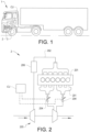
- Fig. 1 depicts a heavy-duty vehicle 1 in the form of a truck.
- the vehicle comprises a drivetrain.
- the drivetrain comprises a propulsion arrangement 2, 3, for the propulsion of the vehicle.
- the propulsion arrangement comprises an internal combustion engine 2, and a gearbox 3.
- the gearbox is in this embodiment an automatic transmission.
- the gearbox has in this example twelve gears, but a different number of gears is of course possible.
- a control unit CU is provided to control the engine 2 and the gearbox 3. It is understood that the control unit CU may be provided as a single physical unit, or as a plurality of physical units.
- the vehicle further comprises service brakes, (not shown).
- the engine in this example comprises six cylinders arranged in a line.
- the engine is a diesel engine.
- the invention is equally applicable to other types of engines, such as Otto engines.
- the engine comprises a turbocharger 205, an air guide 202 with a charge air cooler 206, and a fuel system (not shown).
- the exhaust conduit arrangement comprises two exhaust guides 203, each arranged to guide a gas flow from a respective group of the cylinders, to a turbine of the turbocharger 205.
- an adjustable exhaust flow restriction element 204 is provided, in the form of an exhaust throttle valve.
- the exhaust flow restriction elements 204 are controllable by the control unit CU.
- Each of the flow restriction elements 204 is arranged to provide a plurality of levels of the exhaust flow restriction depending on the adjustment by the control unit CU of the respective exhaust flow restriction element 204.
- the control unit CU is arranged to determine a requested engine braking torque.
- the control unit CU is further arranged to control an actual engine braking torque, towards the requested engine braking torque, by means of the exhaust flow restriction elements 204.
- the control unit CU obtains values of the engine rotational speed, which may be determined by means of an engine speed sensor.
- the control unit CU may be provided with stored data correlating values of the engine torque and the engine rotational speed with settings for the exhaust flow restriction elements 204. Further input parameters in the engine break control may be the pressure in the exhaust guides, and/or the air flow in the air guide 202, determined e.g. by means of an air flow sensor (not shown).
- the control unit CU may be arranged to access stored data correlating values of the engine torque and the engine rotational speed with desired values of the air guide pressure.
- a single exhaust guide with a single exhaust flow restriction element 204, may be arranged to guide exhaust gases from all cylinders of the engine.
- an exhaust flow restriction element 204 may be provided downstream of the turbine of the turbocharger 205.
- the engine braking torque may be controlled by means of a variable geometry turbocharger.
- Fig. 3 depicts steps in a method, according to an embodiment of the invention, for controlling engine braking of a vehicle 1 driving along a downhill portion of a road.
- the method comprises dividing S1 the road portion into a plurality of sections RS0-RS2.
- the sections comprise what is referred to herein as a first section RS1, and a second section RS2 following, in the direction of travel of the vehicle, immediately upon the first section RS1.
- the division of the road portion is made such that each section RS0-RS2 has a substantially constant declination.
- stretches forming a transition between two road inclinations form divisions between adjacent sections RS0-RS2.
- the division of the road portion is made so that curves, entailing a vehicle speed restriction, also form divisions between adjacent sections.
- the road portion division may be done at least partly based on map data.
- the method may further comprise obtaining a reference speed profile SPr for the road portion.
- the reference speed profile SPr may be a stored speed profile.
- the reference speed profile SPr may have recorded during a previous travel of the vehicle 1, or another vehicle, on the road portion.
- the method further comprises determining, for the road portion, a road portion control strategy.
- the road portion control strategy is determined with a condition that braking on the road portion is done by means of the propulsion arrangement 2, 3 only.
- determining the road portion control strategy is done with the condition of avoiding the use of the vehicle service brakes on the road portion.
- the road portion control strategy may be determined with a condition that braking on the road portion is done by means of the propulsion arrangement, and the retarder only.
- the road portion control strategy is determined with a calculation that is opposite to the vehicle travel direction.
- a speed profile for a road section RS1 is determined partly based on a previously determined speed profile for a road section RS2 following immediately after the road section RS1, for which a speed profile is to be determined.
- the road portion control strategy determination comprises determining S3, for the second section RS2, a speed profile, referred to herein as a second section speed profile.
- Determining the second section speed profile comprises S2 determining a speed SD21, on the second section RS2, with an aim to minimize the time travelled on the second section.
- the determined speed SD21 is the highest speed that the vehicle engine brake allows in the second section.
- the second section speed profile is adapted to a speed for the following, third section.
- an end portion of the second section RS2 will have a speed profile, which gradually adjusts, from the highest allowed speed SD21, to said third section speed.
- an initial part of the second section will have constant speed profile with the highest allowed speed SD21.
- said highest allowed speed SD21 on the second section occurs at all positions within the first 75% of the second section RS2.
- a first section control strategy is determined S4 for the first section RS1, with an aim to minimize the time travelled on the first section, and to provide a vehicle speed at the end of the first section RS1 which is the same as said determined speed SD21 on the second section RS2.
- Determining the first section control strategy comprises determining, for the first section, a first section speed profile SP1. It should be noted that in some embodiments, the second section speed profile does not have to be determined before the first section speed profile SP1 is determined. In some embodiments, the first section speed profile SP1 may be determined upon merely determining said speed SD21 on the second section RS2.
- the first section control strategy determination comprises determining S4, for the first section RS1, a first section gear selection strategy, with an aim to provide a gear selection at the end of the first section which is the same as said determined gear selection GS2 on the second section RS2. It should be noted that in some embodiments, the second section gear selection strategy does not have to be determined before the first section gear selection strategy is determined. In some embodiments, the first section gear selection strategy may be determined upon merely determining said gear selection GS2 on the second section RS2.
- the determinations of the first section speed profile SP1, and the first section gear selection strategy are in this embodiment performed as follows: Forces acting on the vehicle are determined. This could be done using a vehicle model. The vehicle model could be stored in the control unit CU. A force pulling the vehicle in the direction of travel is a component of gravity F g ( t ) acting along the road, which component is dependent on the road declination. Opposite to the direction of travel there is a resistive force F r ( l ), resisting the vehicle motion. The resistive force could be the result of a plurality of contributors, such as air drag, rolling resistance, driveline and engine frictions, etc. It is understood that the resistive force may be dependent on the vehicle speed.
- the effective force accelerating the vehicle downhill is the difference between said gravity component and the resistive force.
- the braking force F b ( t ) is dependent on the gear selection, as exemplified below.
- the braking force F b ( t ) may be dependent on an engine oil temperature, limitations due to the road being slippery, the engine or output shaft speed, etc. The dependence on such operational circumstances may be included in the vehicle model.
- Determining the first section speed profile SP1 may be achieved by minimizing a cost function. Minimizing the cost function may involve finding a first section speed profile SP1, which maximizes the integral of the speed profile, while avoiding the use of the service brakes.
- the integral of the speed profile SP1 is the area under the line SP1 in fig. 4b . Thus, the integral may have the distance travelled s as an independent variable. It should be noted that such a cost function may be used without the involvement of the reference speed profile SPr.
- the first section speed profile SP1 may be achieved by the minimization of the following cost function:
- the cost function is solved by a numerical optimization method.
- this optimization method comprises a stochastic/analytical hybrid algorithm with the following steps: Based at least partly on the vehicle mass, and the declination of the first section RS1, the gravity component F g ( t ), the resistive force F r ( l ) are determined.
- the resistive force may be determined based on a speed of the reference speed profile. In some embodiments, the resistive force could be approximated as speed independent, e.g. by ignoring the air drag contribution.
- the absolute value of the required engine braking force F b ( t ) is equal to the sum of the gravity component F g ( t ), and the resistive force F r ( t ), (one being positive and the other negative).
- Determining the first section speed profile comprises determining a speed SD12, on the first section RS1, with an aim to minimize the time travelled on the first section, the determined speed SD12 is the highest speed that the vehicle engine brake allows in the first section.
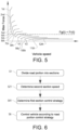
- the maximum braking force for each gear is, at an upper speed interval of the full speed interval for the respective gear, essentially constant, or less increasing with the speed, compared to at a lower speed interval of the full speed interval for the respective gear.
- Said upper speed interval for the 7 th gear is indicated with the interval end values V1 and V2.
- the highest allowed speed SD12 is selected to be within the upper speed interval V1-V2.
- the highest allowed speed SD12 may be at the upper end of the upper speed interval V1-V2.
- the required engine braking force is below the maximum braking force for the 7 th gear.
- a setting, on the first section RS1, of the adjustable exhaust flow restriction element 204, is determined.
- the determined first section highest allowed speed SD12, and the determined second section highest allowed speed SD21 are different.
- the gear selection GS1 on the first section RS1 is not the same as the gear selection GS2 on the second section RS2.
- the speed profile of the first section is determined so as to provide a vehicle speed at the end of the first section RS1 which is the same as said highest allowed speed SD21 on the second section RS2.
- the first section highest allowed speed SD12 becomes an initial speed on the first section.
- the gear selection strategy of the first section is determined so as to provide a gear selection at the end of the first section RS1 which is the same as the gear selection GS2 on the second section RS2. Therefore, the optimization method for the first section speed profile includes, as boundaries, the second section highest allowed speed SD21, and the second section gear selection GS2, at the end of the first section RS1.
- the optimization method involves determining, or generating, a plurality of speed profile candidates for the first section RS1.
- Each speed profile candidate includes a respective intermediate speed SD11 at a position between the start and the end of the first section RS1.
- the intermediate speed SD11 is different from one profile candidate to another.
- the first section speed profile SP1 is selected from the profile candidates.
- the criteria for this selection is to minimize the time travelled on the first section.
- Each speed profile candidate may be associated with a respective gear selection strategy.
- the optimization may take into account that a gear change will increase the speed of the vehicle. This may be taken into account for selecting between a gear strategy which changes from one gear to another via one or more intermediate gears, and a gear strategy which changes directly from the one gear to the other gear.
- the optimization method may involve the use of CMA-ES (Covariance Matrix Adaptation Evolution Strategy). Alternatively, another strategy could be used for the optimization method, such as Cross-Entropy, or NSGA-II.
- the plurality of speed profile candidates for the first section RS1 may be randomly generated.
- the amount of generated speed profile candidates may be 50-200, e.g. 100.
- a sub-group is selected.
- the amount of speed profiles in the sub-group could form e.g. a quarter to half of the generated speed profiles.
- the amount of selected speed profiles could be 30.
- the selected speed profiles could be such that they provide the lowest values of the cost function mentioned above.
- the selected speed profiles could be the speed profiles having the highest integral in the distance domain.
- a further set of speed profiles is generated. Another selection is made from the speed profiles in the further set.
- the optimization method could involve a plurality of such iterations.
- the second section RS2 has a higher declination than the first section RS1.
- the first section speed profile SP1 has decreasing speeds at the end of the first section RS1.
- a control strategy for a preceding section RS0, preceding, in the direction of travel of the vehicle, immediately before the first section RS1 is determined.
- the preceding section control strategy is determined similarly to the first section control strategy, described above.
- the preceding section control strategy is determined with an aim to minimize the time travelled on the preceding section RS0, and to provide a vehicle speed at the end of the preceding section which is the same as said initial speed SD12 of the first section speed profile SP1.
- the division of the road portion may be made so that curves, entailing vehicle speed restrictions, also form divisions between adjacent sections.
- a curve, dividing two adjacent sections may have a speed restriction.
- a preceding of the adjacent sections may obtain a speed profile, such that the speed at the end of the preceding section is the speed according to the speed restriction.
- a following of the adjacent sections may obtain a speed profile, such that the speed at the start of the following section is the speed according to the speed restriction.
- the speed profile may have increasing speeds, after the start of the following section, up to a highest allowed speed on the following section.
- control strategies for all sections RS0-RS2 When the control strategies for all sections RS0-RS2 have been determined, they will together form S5 the control strategy for the entire road portion RS0-RS2. Thereupon, the vehicle 1 is controlled S6 according to the determined road portion control strategy.
- one or more section control strategies may be determined in dependence on an engine exhaust temperature, and/or a de-rating of the engine in dependence on the exhaust temperature.
- Alternative computations methods for the optimization method may be used, such as Evolutionary computation, Genetic Algorithms, Monte-Carlo, Tabu-Search, Neural networks, or Dynamic programing.
- Fig. 6 shows steps in a method, according to a more general embodiment of the invention, for controlling braking of a vehicle driving along a downhill portion of a road, the vehicle comprising a propulsion arrangement, for the propulsion of the vehicle.
- the method comprises dividing S1 the road portion into a plurality of sections, the sections comprising a first section, and a second section following, in the direction of travel of the vehicle, immediately upon the first section.
- the method further comprises determining, for the road portion, a road portion control strategy, with a condition that braking on the road portion is done by means of the propulsion arrangement. Determining the road portion control strategy comprises determining S21 a speed on the second section, with an aim to minimize the time travelled on the second section.
- Determining the road portion control strategy comprises determining S41, for the first section, a first section control strategy, with an aim to minimize the time travelled on the first section, and to provide a vehicle speed at the end of the first section which is the same as said determined speed on the second section.
- the method further comprising controlling S6 the vehicle according to the determined road portion control strategy.
Landscapes
- Engineering & Computer Science (AREA)
- Transportation (AREA)
- Mechanical Engineering (AREA)
- Chemical & Material Sciences (AREA)
- Combustion & Propulsion (AREA)
- Automation & Control Theory (AREA)
- Human Computer Interaction (AREA)
- Physics & Mathematics (AREA)
- Mathematical Physics (AREA)
- Control Of Transmission Device (AREA)
Claims (14)
- Verfahren zur Steuerung des Bremsens eines Fahrzeugs (1), das auf einem bergab führenden Abschnitt einer Straße fährt, das Fahrzeug umfassend eine Antriebsanordnung (2, 3) für den Antrieb des Fahrzeugs, das Verfahren umfassend:Unterteilen des Straßenabschnitts in mehrere Abschnitte (RS0-RS2), wobei die Abschnitte einen ersten Abschnitt (RS1) und einen zweiten Abschnitt (RS2) umfassen, der in Fahrtrichtung des Fahrzeugs unmittelbar auf den ersten Abschnitt (RS1) folgt, gekennzeichnet durchBestimmen einer Straßenabschnitt-Steuerstrategie für den Straßenabschnitt unter der Bedingung, dass das Bremsen auf dem Straßenabschnitt mindestens teilweise mit Hilfe der Antriebsanordnung (2, 3) erfolgt, wobei das Bestimmen der Straßenabschnitt-Steuerstrategie Folgendes umfasst:Bestimmen einer Geschwindigkeit (SD21) auf dem zweiten Abschnitt (RS2), um die auf dem zweiten Abschnitt zurückgelegte Zeit zu minimieren, und/oder, wenn die Antriebsanordnung einen Verbrennungsmotor (2) und ein Getriebe (3) umfasst, Bestimmen einer Gangwahl (GS2) auf dem zweiten Abschnitt (RS2), um die auf dem zweiten Abschnitt zurückgelegte Zeit zu minimieren, undBestimmen der Straßenabschnitt-Steuerstrategie das Bestimmen einer ersten Abschnittssteuerstrategie für den ersten Abschnitt (RS1) umfasst, um die auf dem ersten Abschnitt zurückgelegte Zeit zu minimieren, und eine Fahrzeuggeschwindigkeit am Ende des ersten Abschnitts (RS1) bereitzustellen, die die gleiche ist wie die ermittelte Geschwindigkeit (SD21) auf dem zweiten Abschnitt (RS2), und/oder um eine Gangwahl am Ende des ersten Abschnitts bereitzustellen, die die gleiche ist wie die ermittelte Gangwahl (GS2) auf dem zweiten Abschnitt (RS2), wobeidie Steuerstrategie auf dem ersten Abschnitt und/oder die Geschwindigkeit auf dem zweiten Abschnitt mindestens teilweise auf der Grundlage von Daten bestimmt wird, die die maximal verfügbare Bremskraft als eine Funktion der Fahrzeuggeschwindigkeit anzeigen, und das Verfahren ferner das Steuern des Fahrzeugs (1) gemäß der bestimmten Straßenabschnitt-Steuerstrategie umfasst.
- Verfahren nach Anspruch 1, wobei die Geschwindigkeit (SD21) auf dem zweiten Abschnitt (RS2) bestimmt wird, bevor die erste Abschnittssteuerstrategie bestimmt wird.
- Verfahren nach einem der vorhergehenden Ansprüche, wobei der erste Abschnitt eine konstante Neigung aufweist.
- Verfahren nach einem der vorhergehenden Ansprüche, wobei das Fahrzeug Betriebsbremsen umfasst, wobei das Bestimmen der Straßenabschnitt-Steuerstrategie unter der Bedingung erfolgt, dass der Einsatz der Betriebsbremsen auf dem Straßenabschnitt vermieden wird.
- Verfahren nach einem der vorhergehenden Ansprüche, wobei Bestimmen der Straßenabschnitt-Steuerstrategie das Bestimmen einer zweiten Abschnittssteuerstrategie für den zweiten Abschnitt (RS2) umfasst, wobei das Bestimmen der zweiten Abschnittssteuerstrategie das Bestimmen der zweiten Abschnittsgeschwindigkeit (SD21) umfasst.
- Verfahren nach Anspruch 5, wobei die zweite Abschnittssteuerstrategie vor dem Bestimmen der ersten Abschnittssteuerstrategie bestimmt wird.
- Verfahren nach einem der Ansprüche 5-6, wobei Bestimmen der zweiten Abschnittssteuerstrategie das Bestimmen eines Geschwindigkeitsprofils für den zweiten Abschnitt (RS2) umfasst.
- Verfahren nach Anspruch 7, wobei die bestimmte Geschwindigkeit (SD21) auf dem zweiten Abschnitt an mehreren Positionen innerhalb der ersten 10 %, vorzugsweise der ersten 30 %, noch bevorzugter der ersten 50 %, des zweiten Abschnitts (RS2) auftritt.
- Verfahren nach einem der vorhergehenden Ansprüche, dadurch gekennzeichnet, dass das Bestimmen der ersten Abschnittssteuerstrategie das Bestimmen eines ersten Abschnittsgeschwindigkeitsprofils (SP1) für den ersten Abschnitt umfasst.
- Verfahren nach einem der vorhergehenden Ansprüche, wobei die Gangwahl (GS2) auf dem zweiten Abschnitt bestimmt wird, bevor die erste Abschnittssteuerstrategie bestimmt wird.
- Verfahren nach einem der vorhergehenden Ansprüche, bei dem eine Strategie für eine Einstellung an dem ersten Abschnitt (RS1) und/oder eine Einstellung an dem zweiten Abschnitt (RS2) einer Vorrichtung (204) zur Steuerung einer Motorbremskraft des Motors bestimmt wird.
- Computerprogramm, das Programmcodemittel zum Durchführen der Schritte nach einem der Ansprüche 1-13 umfasst, wenn das Programm auf einem Computer oder einer Gruppe von Computern ausgeführt wird.
- Steuereinheit, die konfiguriert ist, um die Schritte des Verfahrens gemäß einem der Ansprüche 1-12 durchzuführen.
- Fahrzeug, das eine Steuereinheit nach Anspruch 13 umfasst.
Applications Claiming Priority (1)
| Application Number | Priority Date | Filing Date | Title |
|---|---|---|---|
| PCT/EP2019/063102 WO2020233795A1 (en) | 2019-05-21 | 2019-05-21 | A method for controlling braking of a vehicle |
Publications (3)
| Publication Number | Publication Date |
|---|---|
| EP3972881A1 EP3972881A1 (de) | 2022-03-30 |
| EP3972881C0 EP3972881C0 (de) | 2024-10-23 |
| EP3972881B1 true EP3972881B1 (de) | 2024-10-23 |
Family
ID=66640981
Family Applications (1)
| Application Number | Title | Priority Date | Filing Date |
|---|---|---|---|
| EP19725987.2A Active EP3972881B1 (de) | 2019-05-21 | 2019-05-21 | Verfahren zur steuerung des bremsens eines fahrzeugs |
Country Status (4)
| Country | Link |
|---|---|
| US (1) | US11713040B2 (de) |
| EP (1) | EP3972881B1 (de) |
| CN (1) | CN113840761B (de) |
| WO (1) | WO2020233795A1 (de) |
Families Citing this family (2)
| Publication number | Priority date | Publication date | Assignee | Title |
|---|---|---|---|---|
| EP4350171A1 (de) * | 2022-10-03 | 2024-04-10 | Volvo Truck Corporation | Antriebsstrang für ein fahrzeug, fahrzeug mit dem antriebsstrang und heizverfahren mit dem antriebsstrang |
| EP4368462B1 (de) | 2022-11-11 | 2025-08-20 | Volvo Truck Corporation | Schwerlastfahrzeug |
Citations (1)
| Publication number | Priority date | Publication date | Assignee | Title |
|---|---|---|---|---|
| WO2015178838A1 (en) * | 2014-05-21 | 2015-11-26 | Scania Cv Ab | Method and system for improving the operating efficiency of a vehicle during driving of a vehicle along a route of travel |
Family Cites Families (17)
| Publication number | Priority date | Publication date | Assignee | Title |
|---|---|---|---|---|
| JP2005226670A (ja) * | 2004-02-10 | 2005-08-25 | Toyota Motor Corp | 車両の減速制御装置 |
| SE529578C2 (sv) | 2005-04-04 | 2007-09-25 | Scania Cv Abp | Ett förfarande och ett system för att styra driften av ett fordon |
| CN101209681B (zh) * | 2006-12-26 | 2010-09-29 | 比亚迪股份有限公司 | 电动汽车下坡状态下电机输出转矩控制系统及控制方法 |
| JP4322926B2 (ja) * | 2007-01-23 | 2009-09-02 | 本田技研工業株式会社 | 車両用自動変速機の制御装置 |
| US7908067B2 (en) * | 2007-12-05 | 2011-03-15 | Ford Global Technologies, Llc | Hybrid electric vehicle braking downshift control |
| JP6304165B2 (ja) * | 2015-07-31 | 2018-04-04 | トヨタ自動車株式会社 | ハイブリッド車両の制御装置 |
| US10647320B2 (en) * | 2015-08-28 | 2020-05-12 | Volvo Truck Corporation | Method and a system for controlling vehicle speed |
| WO2017079569A1 (en) | 2015-11-04 | 2017-05-11 | Cummins, Inc. | Driveline disengagement and coasting management |
| DE102015015923A1 (de) * | 2015-12-09 | 2017-06-14 | Wabco Gmbh | Verfahren zum adaptiven Regeln einer Fahrzeuggeschwindigkeit in einem Fahrzeug sowie Geschwindigkeitsregelanlage zum Durchführen des Verfahrens |
| US10843680B2 (en) * | 2016-06-07 | 2020-11-24 | Lenovo (Singapore) Pte. Ltd. | Managing battery and engine power to propel vehicle based on upcoming road feature |
| WO2017221233A1 (en) | 2016-06-19 | 2017-12-28 | Joshua Waldhorn | System and method for optimized cruise control |
| US10203031B2 (en) * | 2016-07-19 | 2019-02-12 | Toyota Motor Engineering & Manufacturing North America, Inc. | System and method for changing driving modes using navigation and control |
| KR101886535B1 (ko) * | 2016-12-23 | 2018-08-07 | 현대 파워텍 주식회사 | 내리막길에서 무단 변속기의 변속 제어방법 |
| JP6780580B2 (ja) * | 2017-05-12 | 2020-11-04 | トヨタ自動車株式会社 | 車両の制御装置 |
| DE102017004819A1 (de) * | 2017-05-18 | 2018-11-22 | Man Truck & Bus Ag | Betriebsverfahren für ein Fahrerassistenzsystem und Kraftfahrzeug |
| KR102274125B1 (ko) * | 2017-06-28 | 2021-07-06 | 현대자동차주식회사 | 친환경 자동차의 관성 주행 제어 방법 |
| CN107826124B (zh) * | 2017-11-02 | 2020-06-02 | 潍柴动力股份有限公司 | 一种基于发动机制动的整车下坡提示方法及系统 |
-
2019
- 2019-05-21 WO PCT/EP2019/063102 patent/WO2020233795A1/en not_active Ceased
- 2019-05-21 CN CN201980096553.2A patent/CN113840761B/zh active Active
- 2019-05-21 US US17/595,547 patent/US11713040B2/en active Active
- 2019-05-21 EP EP19725987.2A patent/EP3972881B1/de active Active
Patent Citations (1)
| Publication number | Priority date | Publication date | Assignee | Title |
|---|---|---|---|---|
| WO2015178838A1 (en) * | 2014-05-21 | 2015-11-26 | Scania Cv Ab | Method and system for improving the operating efficiency of a vehicle during driving of a vehicle along a route of travel |
Also Published As
| Publication number | Publication date |
|---|---|
| US11713040B2 (en) | 2023-08-01 |
| EP3972881A1 (de) | 2022-03-30 |
| US20220212664A1 (en) | 2022-07-07 |
| WO2020233795A1 (en) | 2020-11-26 |
| EP3972881C0 (de) | 2024-10-23 |
| CN113840761B (zh) | 2023-09-29 |
| CN113840761A (zh) | 2021-12-24 |
Similar Documents
| Publication | Publication Date | Title |
|---|---|---|
| US11072329B2 (en) | Ground vehicle control techniques | |
| CN102395817B (zh) | 变速器控制装置 | |
| US9821803B2 (en) | Vehicle speed and coasting control method and system | |
| EP2718159B1 (de) | Verfahren und system für ein fahrzeug | |
| CN109760667B (zh) | 车辆控制装置 | |
| US9694826B1 (en) | Vehicle controls for determining optimal gear shifting opportunities using dynamically determined vehicle parameters | |
| US20170291605A1 (en) | Optimized fuel economy during cruise control using topography data | |
| van Keulen et al. | Optimal energy management in hybrid electric trucks using route information | |
| SE0950437A1 (sv) | Modul i ett styrsystem för ett fordon | |
| CN101344167B (zh) | 车辆的变速系统、自动变速器的控制方法及控制装置 | |
| CN108099896A (zh) | 使用预测信息进行的再生制动降挡控制 | |
| SE0950971A1 (sv) | Förfarande och system för framförande av ett fordon | |
| CN107792048A (zh) | 变矩器离合器接合压力 | |
| SE1050335A1 (sv) | Metod och modul i samband med farthållning | |
| EP2219092A1 (de) | Verfahren zum Regeln der Geschwindigkeit eines Fahrzeuges | |
| WO2017075578A1 (en) | Systems and methods for idle coasting management | |
| CN110792762A (zh) | 一种巡航模式下商用车前瞻换挡控制方法 | |
| EP3972881B1 (de) | Verfahren zur steuerung des bremsens eines fahrzeugs | |
| Koch-Groeber et al. | Criteria for coasting on highways for passenger cars | |
| CN103119335A (zh) | 用于自动化的多级换挡变速器的换挡控制的方法 | |
| WO2016007073A1 (en) | Control of an internal combustion engine in a vehicle | |
| CN114651143B (zh) | 用于控制车辆的变速器的方法 | |
| JP2018122818A (ja) | 走行制御装置および走行制御方法 | |
| EP3209533B1 (de) | Verfahren und system zum antrieb eines fahrzeuges | |
| EP3166831B1 (de) | Steuerung von vorbereitungsmassnahmen in einem fahrzeug |
Legal Events
| Date | Code | Title | Description |
|---|---|---|---|
| STAA | Information on the status of an ep patent application or granted ep patent |
Free format text: STATUS: UNKNOWN |
|
| STAA | Information on the status of an ep patent application or granted ep patent |
Free format text: STATUS: THE INTERNATIONAL PUBLICATION HAS BEEN MADE |
|
| PUAI | Public reference made under article 153(3) epc to a published international application that has entered the european phase |
Free format text: ORIGINAL CODE: 0009012 |
|
| STAA | Information on the status of an ep patent application or granted ep patent |
Free format text: STATUS: REQUEST FOR EXAMINATION WAS MADE |
|
| 17P | Request for examination filed |
Effective date: 20211119 |
|
| AK | Designated contracting states |
Kind code of ref document: A1 Designated state(s): AL AT BE BG CH CY CZ DE DK EE ES FI FR GB GR HR HU IE IS IT LI LT LU LV MC MK MT NL NO PL PT RO RS SE SI SK SM TR |
|
| DAV | Request for validation of the european patent (deleted) | ||
| DAX | Request for extension of the european patent (deleted) | ||
| STAA | Information on the status of an ep patent application or granted ep patent |
Free format text: STATUS: EXAMINATION IS IN PROGRESS |
|
| 17Q | First examination report despatched |
Effective date: 20221004 |
|
| REG | Reference to a national code |
Ref country code: DE Ref legal event code: R079 Free format text: PREVIOUS MAIN CLASS: B60W0010040000 Ipc: B60W0030180000 Ref document number: 602019060772 Country of ref document: DE |
|
| GRAJ | Information related to disapproval of communication of intention to grant by the applicant or resumption of examination proceedings by the epo deleted |
Free format text: ORIGINAL CODE: EPIDOSDIGR1 |
|
| STAA | Information on the status of an ep patent application or granted ep patent |
Free format text: STATUS: GRANT OF PATENT IS INTENDED |
|
| GRAP | Despatch of communication of intention to grant a patent |
Free format text: ORIGINAL CODE: EPIDOSNIGR1 |
|
| RIC1 | Information provided on ipc code assigned before grant |
Ipc: B60W 30/18 20120101AFI20240502BHEP |
|
| INTG | Intention to grant announced |
Effective date: 20240522 |
|
| GRAS | Grant fee paid |
Free format text: ORIGINAL CODE: EPIDOSNIGR3 |
|
| GRAA | (expected) grant |
Free format text: ORIGINAL CODE: 0009210 |
|
| STAA | Information on the status of an ep patent application or granted ep patent |
Free format text: STATUS: THE PATENT HAS BEEN GRANTED |
|
| AK | Designated contracting states |
Kind code of ref document: B1 Designated state(s): AL AT BE BG CH CY CZ DE DK EE ES FI FR GB GR HR HU IE IS IT LI LT LU LV MC MK MT NL NO PL PT RO RS SE SI SK SM TR |
|
| REG | Reference to a national code |
Ref country code: GB Ref legal event code: FG4D |
|
| REG | Reference to a national code |
Ref country code: CH Ref legal event code: EP |
|
| REG | Reference to a national code |
Ref country code: DE Ref legal event code: R096 Ref document number: 602019060772 Country of ref document: DE |
|
| REG | Reference to a national code |
Ref country code: IE Ref legal event code: FG4D |
|
| U01 | Request for unitary effect filed |
Effective date: 20241115 |
|
| U07 | Unitary effect registered |
Designated state(s): AT BE BG DE DK EE FI FR IT LT LU LV MT NL PT RO SE SI Effective date: 20241121 |
|
| PG25 | Lapsed in a contracting state [announced via postgrant information from national office to epo] |
Ref country code: IS Free format text: LAPSE BECAUSE OF FAILURE TO SUBMIT A TRANSLATION OF THE DESCRIPTION OR TO PAY THE FEE WITHIN THE PRESCRIBED TIME-LIMIT Effective date: 20250223 Ref country code: HR Free format text: LAPSE BECAUSE OF FAILURE TO SUBMIT A TRANSLATION OF THE DESCRIPTION OR TO PAY THE FEE WITHIN THE PRESCRIBED TIME-LIMIT Effective date: 20241023 |
|
| PG25 | Lapsed in a contracting state [announced via postgrant information from national office to epo] |
Ref country code: ES Free format text: LAPSE BECAUSE OF FAILURE TO SUBMIT A TRANSLATION OF THE DESCRIPTION OR TO PAY THE FEE WITHIN THE PRESCRIBED TIME-LIMIT Effective date: 20241023 |
|
| PG25 | Lapsed in a contracting state [announced via postgrant information from national office to epo] |
Ref country code: NO Free format text: LAPSE BECAUSE OF FAILURE TO SUBMIT A TRANSLATION OF THE DESCRIPTION OR TO PAY THE FEE WITHIN THE PRESCRIBED TIME-LIMIT Effective date: 20250123 |
|
| PG25 | Lapsed in a contracting state [announced via postgrant information from national office to epo] |
Ref country code: GR Free format text: LAPSE BECAUSE OF FAILURE TO SUBMIT A TRANSLATION OF THE DESCRIPTION OR TO PAY THE FEE WITHIN THE PRESCRIBED TIME-LIMIT Effective date: 20250124 |
|
| PG25 | Lapsed in a contracting state [announced via postgrant information from national office to epo] |
Ref country code: PL Free format text: LAPSE BECAUSE OF FAILURE TO SUBMIT A TRANSLATION OF THE DESCRIPTION OR TO PAY THE FEE WITHIN THE PRESCRIBED TIME-LIMIT Effective date: 20241023 |
|
| PG25 | Lapsed in a contracting state [announced via postgrant information from national office to epo] |
Ref country code: RS Free format text: LAPSE BECAUSE OF FAILURE TO SUBMIT A TRANSLATION OF THE DESCRIPTION OR TO PAY THE FEE WITHIN THE PRESCRIBED TIME-LIMIT Effective date: 20250123 |
|
| U20 | Renewal fee for the european patent with unitary effect paid |
Year of fee payment: 7 Effective date: 20250526 |
|
| PG25 | Lapsed in a contracting state [announced via postgrant information from national office to epo] |
Ref country code: SM Free format text: LAPSE BECAUSE OF FAILURE TO SUBMIT A TRANSLATION OF THE DESCRIPTION OR TO PAY THE FEE WITHIN THE PRESCRIBED TIME-LIMIT Effective date: 20241023 |
|
| PG25 | Lapsed in a contracting state [announced via postgrant information from national office to epo] |
Ref country code: SK Free format text: LAPSE BECAUSE OF FAILURE TO SUBMIT A TRANSLATION OF THE DESCRIPTION OR TO PAY THE FEE WITHIN THE PRESCRIBED TIME-LIMIT Effective date: 20241023 |
|
| PG25 | Lapsed in a contracting state [announced via postgrant information from national office to epo] |
Ref country code: CZ Free format text: LAPSE BECAUSE OF FAILURE TO SUBMIT A TRANSLATION OF THE DESCRIPTION OR TO PAY THE FEE WITHIN THE PRESCRIBED TIME-LIMIT Effective date: 20241023 |
|
| PLBE | No opposition filed within time limit |
Free format text: ORIGINAL CODE: 0009261 |
|
| STAA | Information on the status of an ep patent application or granted ep patent |
Free format text: STATUS: NO OPPOSITION FILED WITHIN TIME LIMIT |
|
| 26N | No opposition filed |
Effective date: 20250724 |