EP3209533B1 - Verfahren und system zum antrieb eines fahrzeuges - Google Patents
Verfahren und system zum antrieb eines fahrzeuges Download PDFInfo
- Publication number
- EP3209533B1 EP3209533B1 EP15853493.3A EP15853493A EP3209533B1 EP 3209533 B1 EP3209533 B1 EP 3209533B1 EP 15853493 A EP15853493 A EP 15853493A EP 3209533 B1 EP3209533 B1 EP 3209533B1
- Authority
- EP
- European Patent Office
- Prior art keywords
- vehicle
- torque
- segment
- speed
- determining
- Prior art date
- Legal status (The legal status is an assumption and is not a legal conclusion. Google has not performed a legal analysis and makes no representation as to the accuracy of the status listed.)
- Active
Links
- 238000000034 method Methods 0.000 title claims description 35
- 238000004590 computer program Methods 0.000 claims description 14
- 238000012876 topography Methods 0.000 claims description 5
- 230000006870 function Effects 0.000 description 36
- 238000002485 combustion reaction Methods 0.000 description 27
- 239000000446 fuel Substances 0.000 description 22
- 238000012545 processing Methods 0.000 description 9
- 238000011217 control strategy Methods 0.000 description 6
- 238000005265 energy consumption Methods 0.000 description 5
- 238000004364 calculation method Methods 0.000 description 4
- 238000004088 simulation Methods 0.000 description 4
- 238000004891 communication Methods 0.000 description 3
- 230000005484 gravity Effects 0.000 description 3
- 230000008901 benefit Effects 0.000 description 2
- 230000006399 behavior Effects 0.000 description 1
- 238000004422 calculation algorithm Methods 0.000 description 1
- 238000006243 chemical reaction Methods 0.000 description 1
- 230000001419 dependent effect Effects 0.000 description 1
- 238000005259 measurement Methods 0.000 description 1
- 238000012546 transfer Methods 0.000 description 1
Images


Classifications
-
- B—PERFORMING OPERATIONS; TRANSPORTING
- B60—VEHICLES IN GENERAL
- B60W—CONJOINT CONTROL OF VEHICLE SUB-UNITS OF DIFFERENT TYPE OR DIFFERENT FUNCTION; CONTROL SYSTEMS SPECIALLY ADAPTED FOR HYBRID VEHICLES; ROAD VEHICLE DRIVE CONTROL SYSTEMS FOR PURPOSES NOT RELATED TO THE CONTROL OF A PARTICULAR SUB-UNIT
- B60W30/00—Purposes of road vehicle drive control systems not related to the control of a particular sub-unit, e.g. of systems using conjoint control of vehicle sub-units
- B60W30/14—Adaptive cruise control
-
- B—PERFORMING OPERATIONS; TRANSPORTING
- B60—VEHICLES IN GENERAL
- B60W—CONJOINT CONTROL OF VEHICLE SUB-UNITS OF DIFFERENT TYPE OR DIFFERENT FUNCTION; CONTROL SYSTEMS SPECIALLY ADAPTED FOR HYBRID VEHICLES; ROAD VEHICLE DRIVE CONTROL SYSTEMS FOR PURPOSES NOT RELATED TO THE CONTROL OF A PARTICULAR SUB-UNIT
- B60W30/00—Purposes of road vehicle drive control systems not related to the control of a particular sub-unit, e.g. of systems using conjoint control of vehicle sub-units
- B60W30/18—Propelling the vehicle
-
- B—PERFORMING OPERATIONS; TRANSPORTING
- B60—VEHICLES IN GENERAL
- B60W—CONJOINT CONTROL OF VEHICLE SUB-UNITS OF DIFFERENT TYPE OR DIFFERENT FUNCTION; CONTROL SYSTEMS SPECIALLY ADAPTED FOR HYBRID VEHICLES; ROAD VEHICLE DRIVE CONTROL SYSTEMS FOR PURPOSES NOT RELATED TO THE CONTROL OF A PARTICULAR SUB-UNIT
- B60W10/00—Conjoint control of vehicle sub-units of different type or different function
- B60W10/04—Conjoint control of vehicle sub-units of different type or different function including control of propulsion units
- B60W10/06—Conjoint control of vehicle sub-units of different type or different function including control of propulsion units including control of combustion engines
-
- B—PERFORMING OPERATIONS; TRANSPORTING
- B60—VEHICLES IN GENERAL
- B60W—CONJOINT CONTROL OF VEHICLE SUB-UNITS OF DIFFERENT TYPE OR DIFFERENT FUNCTION; CONTROL SYSTEMS SPECIALLY ADAPTED FOR HYBRID VEHICLES; ROAD VEHICLE DRIVE CONTROL SYSTEMS FOR PURPOSES NOT RELATED TO THE CONTROL OF A PARTICULAR SUB-UNIT
- B60W30/00—Purposes of road vehicle drive control systems not related to the control of a particular sub-unit, e.g. of systems using conjoint control of vehicle sub-units
- B60W30/14—Adaptive cruise control
- B60W30/143—Speed control
- B60W30/146—Speed limiting
-
- B—PERFORMING OPERATIONS; TRANSPORTING
- B60—VEHICLES IN GENERAL
- B60W—CONJOINT CONTROL OF VEHICLE SUB-UNITS OF DIFFERENT TYPE OR DIFFERENT FUNCTION; CONTROL SYSTEMS SPECIALLY ADAPTED FOR HYBRID VEHICLES; ROAD VEHICLE DRIVE CONTROL SYSTEMS FOR PURPOSES NOT RELATED TO THE CONTROL OF A PARTICULAR SUB-UNIT
- B60W30/00—Purposes of road vehicle drive control systems not related to the control of a particular sub-unit, e.g. of systems using conjoint control of vehicle sub-units
- B60W30/18—Propelling the vehicle
- B60W30/188—Controlling power parameters of the driveline, e.g. determining the required power
- B60W30/1882—Controlling power parameters of the driveline, e.g. determining the required power characterised by the working point of the engine, e.g. by using engine output chart
-
- B—PERFORMING OPERATIONS; TRANSPORTING
- B60—VEHICLES IN GENERAL
- B60W—CONJOINT CONTROL OF VEHICLE SUB-UNITS OF DIFFERENT TYPE OR DIFFERENT FUNCTION; CONTROL SYSTEMS SPECIALLY ADAPTED FOR HYBRID VEHICLES; ROAD VEHICLE DRIVE CONTROL SYSTEMS FOR PURPOSES NOT RELATED TO THE CONTROL OF A PARTICULAR SUB-UNIT
- B60W40/00—Estimation or calculation of non-directly measurable driving parameters for road vehicle drive control systems not related to the control of a particular sub unit, e.g. by using mathematical models
- B60W40/02—Estimation or calculation of non-directly measurable driving parameters for road vehicle drive control systems not related to the control of a particular sub unit, e.g. by using mathematical models related to ambient conditions
- B60W40/06—Road conditions
- B60W40/076—Slope angle of the road
-
- B—PERFORMING OPERATIONS; TRANSPORTING
- B60—VEHICLES IN GENERAL
- B60W—CONJOINT CONTROL OF VEHICLE SUB-UNITS OF DIFFERENT TYPE OR DIFFERENT FUNCTION; CONTROL SYSTEMS SPECIALLY ADAPTED FOR HYBRID VEHICLES; ROAD VEHICLE DRIVE CONTROL SYSTEMS FOR PURPOSES NOT RELATED TO THE CONTROL OF A PARTICULAR SUB-UNIT
- B60W50/00—Details of control systems for road vehicle drive control not related to the control of a particular sub-unit, e.g. process diagnostic or vehicle driver interfaces
- B60W50/0097—Predicting future conditions
-
- B—PERFORMING OPERATIONS; TRANSPORTING
- B60—VEHICLES IN GENERAL
- B60W—CONJOINT CONTROL OF VEHICLE SUB-UNITS OF DIFFERENT TYPE OR DIFFERENT FUNCTION; CONTROL SYSTEMS SPECIALLY ADAPTED FOR HYBRID VEHICLES; ROAD VEHICLE DRIVE CONTROL SYSTEMS FOR PURPOSES NOT RELATED TO THE CONTROL OF A PARTICULAR SUB-UNIT
- B60W2520/00—Input parameters relating to overall vehicle dynamics
- B60W2520/10—Longitudinal speed
-
- B—PERFORMING OPERATIONS; TRANSPORTING
- B60—VEHICLES IN GENERAL
- B60W—CONJOINT CONTROL OF VEHICLE SUB-UNITS OF DIFFERENT TYPE OR DIFFERENT FUNCTION; CONTROL SYSTEMS SPECIALLY ADAPTED FOR HYBRID VEHICLES; ROAD VEHICLE DRIVE CONTROL SYSTEMS FOR PURPOSES NOT RELATED TO THE CONTROL OF A PARTICULAR SUB-UNIT
- B60W2552/00—Input parameters relating to infrastructure
- B60W2552/20—Road profile, i.e. the change in elevation or curvature of a plurality of continuous road segments
-
- B—PERFORMING OPERATIONS; TRANSPORTING
- B60—VEHICLES IN GENERAL
- B60W—CONJOINT CONTROL OF VEHICLE SUB-UNITS OF DIFFERENT TYPE OR DIFFERENT FUNCTION; CONTROL SYSTEMS SPECIALLY ADAPTED FOR HYBRID VEHICLES; ROAD VEHICLE DRIVE CONTROL SYSTEMS FOR PURPOSES NOT RELATED TO THE CONTROL OF A PARTICULAR SUB-UNIT
- B60W2556/00—Input parameters relating to data
- B60W2556/45—External transmission of data to or from the vehicle
- B60W2556/50—External transmission of data to or from the vehicle of positioning data, e.g. GPS [Global Positioning System] data
-
- B—PERFORMING OPERATIONS; TRANSPORTING
- B60—VEHICLES IN GENERAL
- B60W—CONJOINT CONTROL OF VEHICLE SUB-UNITS OF DIFFERENT TYPE OR DIFFERENT FUNCTION; CONTROL SYSTEMS SPECIALLY ADAPTED FOR HYBRID VEHICLES; ROAD VEHICLE DRIVE CONTROL SYSTEMS FOR PURPOSES NOT RELATED TO THE CONTROL OF A PARTICULAR SUB-UNIT
- B60W2710/00—Output or target parameters relating to a particular sub-units
- B60W2710/06—Combustion engines, Gas turbines
- B60W2710/0666—Engine torque
- B60W2710/0672—Torque change rate
-
- B—PERFORMING OPERATIONS; TRANSPORTING
- B60—VEHICLES IN GENERAL
- B60W—CONJOINT CONTROL OF VEHICLE SUB-UNITS OF DIFFERENT TYPE OR DIFFERENT FUNCTION; CONTROL SYSTEMS SPECIALLY ADAPTED FOR HYBRID VEHICLES; ROAD VEHICLE DRIVE CONTROL SYSTEMS FOR PURPOSES NOT RELATED TO THE CONTROL OF A PARTICULAR SUB-UNIT
- B60W2710/00—Output or target parameters relating to a particular sub-units
- B60W2710/08—Electric propulsion units
- B60W2710/083—Torque
-
- B—PERFORMING OPERATIONS; TRANSPORTING
- B60—VEHICLES IN GENERAL
- B60W—CONJOINT CONTROL OF VEHICLE SUB-UNITS OF DIFFERENT TYPE OR DIFFERENT FUNCTION; CONTROL SYSTEMS SPECIALLY ADAPTED FOR HYBRID VEHICLES; ROAD VEHICLE DRIVE CONTROL SYSTEMS FOR PURPOSES NOT RELATED TO THE CONTROL OF A PARTICULAR SUB-UNIT
- B60W2720/00—Output or target parameters relating to overall vehicle dynamics
- B60W2720/10—Longitudinal speed
- B60W2720/103—Speed profile
-
- B—PERFORMING OPERATIONS; TRANSPORTING
- B60—VEHICLES IN GENERAL
- B60W—CONJOINT CONTROL OF VEHICLE SUB-UNITS OF DIFFERENT TYPE OR DIFFERENT FUNCTION; CONTROL SYSTEMS SPECIALLY ADAPTED FOR HYBRID VEHICLES; ROAD VEHICLE DRIVE CONTROL SYSTEMS FOR PURPOSES NOT RELATED TO THE CONTROL OF A PARTICULAR SUB-UNIT
- B60W30/00—Purposes of road vehicle drive control systems not related to the control of a particular sub-unit, e.g. of systems using conjoint control of vehicle sub-units
-
- B—PERFORMING OPERATIONS; TRANSPORTING
- B60—VEHICLES IN GENERAL
- B60W—CONJOINT CONTROL OF VEHICLE SUB-UNITS OF DIFFERENT TYPE OR DIFFERENT FUNCTION; CONTROL SYSTEMS SPECIALLY ADAPTED FOR HYBRID VEHICLES; ROAD VEHICLE DRIVE CONTROL SYSTEMS FOR PURPOSES NOT RELATED TO THE CONTROL OF A PARTICULAR SUB-UNIT
- B60W50/00—Details of control systems for road vehicle drive control not related to the control of a particular sub-unit, e.g. process diagnostic or vehicle driver interfaces
Definitions
- the present invention relates to motor vehicles, and in particular to a method and a system related to propulsion of a vehicle.
- the present invention also relates to a vehicle, as well as a computer program and a computer program product implementing the method according to the invention.
- Fuel consumption is also of interest from an exhaust emission point of view.
- governmental concern in pollution and air quality e.g. in urban areas, has led to adoption of emission standards and rules in many jurisdictions.
- a reduction in fuel consumption facilitates fulfilment of emission standards and rules.
- cruise control systems For example, the use of cruise control systems is commonplace today.
- One common purpose of cruise control systems is to achieve a uniform predetermined velocity in a manner that is comfortable to the driver of the vehicle.
- cruise control systems/functions that strive to adapt the propulsion of the vehicle based on knowledge about the road ahead, so that fuel consumption can be reduced.
- Such a reduction in fuel consumption can, for example, be achieved with the aid of cruise control functions where vehicle speed is allowed to deviate from a speed set by the driver based on knowledge about the vehicle route or other data, so as to thereby achieve a more fuel-economic propulsion of the vehicle.
- the vehicle speed may be reduced to some extent at the end of an uphill stretch that is followed by a downhill stretch of a type where, by means of the force of gravity, the vehicle will be reaccelerated to the desired speed.
- WO 2013/095232 relates to a method for determination of at least one reference value which indicates how a vehicle's speed is to be influenced and which may be used to control at least one control system in a vehicle.
- the invention is characterised by performing the steps of: - making a first prediction and a second prediction of a vehicle speed along a horizon, said first prediction based on an engine torque which retards the vehicle as compared with a conventional cruise control, and said second prediction based on an engine torque which accelerates the vehicle as compared with a conventional cruise control; - comparing said respective first prediction and second prediction of the vehicle speed with a lower limit value and/or an upper limit value which delineate a range within which the vehicle's speed should be; and - determining at least one reference value based on at least one of said respective comparisons and said first prediction and second prediction of the vehicle speed along the horizon.
- This object is achieved by a method according to claim 1.
- a method for propulsion of a vehicle comprising at least one power source for providing power to at least one drive wheel of said vehicle.
- the method includes, when said vehicle is to be driven along a first path:
- the invention provides a method for propulsion of the vehicle that at least in some situations is capable of reducing the consumption of fuel or energy.
- This can, for example, be accomplished by estimating the work that is required from the power source, such as e.g. a combustion engine or an electrical machine, for an upcoming segment of the path along which the vehicle is travelling, such as e.g. an upcoming stretch of road.
- the estimated work is then distributed over the segment of the path in a manner that reduces variations in the torque delivered by the power source at the expense of increased variations in the speed of the vehicle. That is, the propulsion of the vehicle is primarily controlled on the basis of the torque being delivered by the power source, the resulting speed of the vehicle thereby becoming a consequence of the applied torque.
- the estimation of the work that is expected to be delivered by the power source can make use of data regarding the path in front of the vehicle along which the vehicle is travelling, e.g. with regard to a road profile reflecting e.g. hills, valleys and crests of the upcoming segment of the path. Use of such data allows high-accuracy estimation of the work that is required to achieve the desired movement of the vehicle along the segment of the path.
- a representation of the expected torque to be produced by the vehicle power source can be accomplished by e.g. determining a representation of the average torque to be produced when driving said vehicle along said first segment, or a torque profile for e.g. driving said vehicle along said first segment at a set speed.
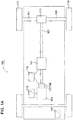
- Fig. 1A schematically shows a power train in a vehicle 100 according to one embodiment of the present invention.
- the power train comprises a combustion engine 101, which, in a conventional manner, is connected via an output shaft of the combustion engine 101, normally via a flywheel 102, to a gearbox 103 via a clutch 106.
- An output shaft 107 from the gearbox 103 propels drive wheels 113, 114 via a final drive 108, such as a common differential, and drive axles 104, 105 connected to said final drive 108.
- the combustion engine 101 is controlled by the vehicle's control system via a control unit 115, and the clutch 106, which, for example, can be an automatically operated clutch, and gearbox 103 are also controlled by the vehicle's control system by means of a control unit 116.
- control systems in modern vehicles usually consist of a communication bus system comprising one or a plurality of communication buses for connecting a number of electronic control units (ECUs), or controllers, and various components arranged in the vehicle.
- ECUs electronice control units
- Such a control system can comprise a large number of control units, and the responsibility for a specific function can be shared among more than one control unit.
- Fig. 1A depicts only the control units 115, 116 and a control unit 117, but vehicles 100 of the illustrated kind are often provided with significantly more control units, as one skilled in the art will appreciate.
- Control units 115-117 can communicate with one another via said communication bus system, partly indicated by interconnecting lines in fig. 1A .
- the present invention can be implemented in any suitable control unit, and in the illustrated example the invention is implemented in control unit 117.
- the control unit 117 is responsible for one or a plurality of cruise control functions for automatically controlling the speed of the vehicle.
- cruise control functions can be of various types and, for example, be of a conventional type being arranged to maintain a speed set by the driver.
- Cruise control functions can also be of kind that uses additional information when controlling the speed of the vehicle.
- the cruise control can make use of a "Look Ahead" function.
- a "Look Ahead" cruise control (LACC) function consists of a cruise control function that uses knowledge about the upcoming section of road, i.e. knowledge about the topography of the road in front of the vehicle, in order to adapt the vehicle velocity based on variations in the road along which the vehicle is travelling.
- the invention can alternatively be implemented in a control unit that is dedicated to the present invention, or wholly or partly in one or a plurality of control units already present in the vehicle 100.
- control unit 117 (or the control unit(s) in which the present invention is implemented) according to the present invention will likely depend on signals that are received from the control unit(s) that control engine functions, i.e. the control unit 115 in the present example.
- the control unit 117 will likely also receive signals from other control units arranged in the vehicle and not shown, and/or information from, for example, various transmitters/ sensors, e.g. positioning sensors, arranged in the vehicle.
- control units of the type shown are normally arranged so as to receive sensor signals from various parts of the vehicle 100.
- Control units of the type shown are also normally arranged so as to transmit control signals to various vehicle parts and components.
- the control unit 117 can demand/order the control unit 115 to control the torque delivered by the combustion engine 101 according to a determined torque profile.
- control units are often controlled by programmed instructions which typically consist of a computer program which, when it is executed in a computer or control unit, causes the computer/control unit to exercise the desired control, such as method steps according to the present invention.
- the computer program usually constitutes a part of a computer program product, where said computer program product comprises a suitable storage medium 121 (see Fig. IB) with the computer program 126 stored on said storage medium 121.
- the computer program can be stored in a non-volatile manner on said storage medium.
- the digital storage medium 121 can, for example, consist of any of the group comprising: ROM (Read-Only Memory), PROM (Programmable Read-Only Memory), EPROM (Erasable PROM), Flash memory, EEPROM (Electrically Erasable PROM), a hard disk unit etc, and be arranged in or in connection with the control unit, whereupon the computer program is executed by the control unit.
- ROM Read-Only Memory
- PROM Programmable Read-Only Memory
- EPROM Erasable PROM
- Flash memory Flash memory
- EEPROM Electrical Erasable PROM
- control unit 117 An exemplary control unit (the control unit 117) is shown schematically in Fig. IB, and the control unit can comprise a processing unit 120, which can consist of, for example, any suitable type of processor or microcomputer, such as a circuit for digital signal processing (Digital Signal Processor, DSP) or a circuit with a predetermined specific function (Application Specific Integrated Circuit, ASIC).
- the processing unit 120 is connected to a memory unit 121, which furnishes the processing unit 120, with e.g. the stored program code 126 and/or the stored data that the processing unit 120 requires to be able to perform calculations.
- the processing unit 120 is also arranged so as to store partial or final results of calculations in the memory unit 121.
- control unit 117 is equipped with devices 122, 123, 124, 125 for receiving and transmitting input and output signals, respectively.
- These input and output signals can comprise waveforms, pulses or other attributes that the devices 122, 125 for receiving input signals can detect as information for processing by the processing unit 120.
- the devices 123, 124 for transmitting output signals are arranged so as to convert calculation results from the processing unit 120 into output signals for transfer to other parts of the vehicle control system and/or the component (s) for which the signals are intended.
- Each and every one of the connections to the devices for receiving and transmitting respective input and output signals can consist of one or more of a cable; a data bus, such as a CAN bus (Controller Area Network bus), a MOST bus (Media Oriented Systems Transport) or any other bus configuration, or of a wireless connection.
- a data bus such as a CAN bus (Controller Area Network bus), a MOST bus (Media Oriented Systems Transport) or any other bus configuration, or of a wireless connection.
- the present invention relates, in particular, to a cruise control function that makes use of information regarding the road in front of the vehicle 100 when controlling the propulsion of the vehicle 100, and which controls the speed of the vehicle 100 in a different manner than prior art solutions.
- An exemplary method 200 according to the present invention is shown in Fig 2 , and the method starts in step 201 where it is determined whether the propulsion of the vehicle 100 is to be controlled by controlling torque according to the present invention.
- the invention is described below for an embodiment where the work to be produced by the vehicle power source is estimated, but the described method is equally applicable e.g. for estimating the average torque to be produced by the vehicle power source, or for estimating a torque profile when driving said vehicle along a segment of road at a set speed.
- the propulsion of the vehicle is controlled according to the present invention at all times, but, as will be explained below, there can also be situations in which the vehicle should be controlled according to some other cruise control function.
- the vehicle should be controlled according to some other cruise control function.
- step 202 the total work W tot that is to be produced by the combustion engine 101 during an upcoming segment of the road along which the vehicle 100 is travelling is estimated.
- This estimation can be performed e.g. using look ahead data and data relating to the vehicle, such as, e.g. current weight of the vehicle etc., where e.g. propulsion of the vehicle for the upcoming segment can be simulated, e.g. for a set cruise control speed, and the total work be determined from the simulation.
- Estimations of this kind are well known to the person skilled in the art, e.g. in the context of look ahead cruise control functions.
- the driving resistance that the vehicle is subjected to can be estimated using on-board data, and this has also been thoroughly described in the prior art.
- the driving resistance in combination with knowledge of the road segment ahead, e.g. with regard to knowledge of the road topography, curvature, properties, etc. allows the required work to be produced by the combustion engine 101 in order to maintain e.g. a set vehicle speed when travelling the road segment to be estimated with high accuracy. Consequently, instead of estimating speed profiles as in the prior art, the total work to be produced by the combustion engine during a road segment is estimated.
- the estimation of the total work W tot can, for example, be estimated for a vehicle speed that has been set by the driver using one or more cruise control functions.
- step 203 a torque profile for controlling the combustion engine 101 is determined.
- the length of the road segment for which the estimated total work W tot is determined can, for example, be a segment having a length of at least 50m, 200m or 500m, or a length in time for the vehicle traversing the segment of at least 3s, 10s, or 30s.
- propulsion of the vehicle is controlled in a different manner, where the propulsion is controlled primarily without regard to the vehicle speed but, instead, with regard to the torque being produced by the combustion engine 101.
- a torque profile T pf of the torque to be delivered by the combustion engine 101 is determined. That is, instead of determining the speed profile where, in general, the speed of the vehicle is kept substantially constant, the propulsion of the vehicle is controlled with regard to the delivered torque instead.
- the torque profile T pf determined according to the present invention is such that variations in the torque being delivered by the combustion engine are reduced at the expense of increased variations in speed of said vehicle. That is, the resulting vehicle speed becomes dependent of the torque being delivered by the combustion engine, and hence the vehicle speed is not used as control parameter. In other words, the vehicle speed is allowed to vary as a consequence of reducing the variations in torque that normally is a result from keeping a set speed.
- the torque profile is determined such that the torque is kept constant, or substantially constant, or being restricted to be within limits about a set torque during the road segment.
- the torque can be set to the average torque that will provide the estimated total work during the road segment.
- the torque variations can be limited to be within some suitable percentage of the average torque, e.g. to average torque ⁇ 20% or average torque ⁇ 40%.
- the torque being kept constant, or torque variations being limited will have the result that vehicle speed will vary with the road profile (crests and valleys etc.) in the road along which the vehicle is travelling.
- the torque can be set to the average torque that will provide the estimated total work during the road segment.
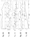
- Figs. 3A-E show an exemplary scenario for the propulsion of the vehicle 100, both according to the prior art and according to the present invention.
- Fig. 3A shows a road (topography) profile of an exemplary section of a road.
- the Figure shows variations in altitude as a function of distance from a point A to a point B.
- Fig. 3B shows a corresponding speed profile of the vehicle when travelling along the road segment showing in Fig. 3A .
- the speed profile of a conventional cruise control function is shown by dashed line 301.
- the conventional cruise control function 301 aims at maintaining the vehicle speed at a set speed v set with only slight variations along most of the road segment.
- variations in vehicle speed occur primarily when driving uphill and downhill, where uphill driving may require vehicle speed to be reduced in order to provide enough power to clear the hill, and where the vehicle speed downhill may increase by the force of gravity.
- Look ahead cruise control functions can, for example, be arranged to allow the vehicle speed to be reduced somewhat when going uphill if the vehicle speed is likely to increase again to the set speed v set by the force of gravity in a following downhill slope.
- Fig. 3B also shows a corresponding speed profile when controlling propulsion of the vehicle 100 according to the present invention. This is illustrated by solid line 302. As can be seen, the variations in speed when controlling the propulsion of the vehicle 100 according to the present invention are considerably larger when compared to cruise control functions of the prior art. The variations are a consequence of the difference in controlling the combustion engine 101. This is illustrated in Fig. 3C where, again, dashed line 303 represents the conventional cruise control function and solid line 304 represents the cruise control function according to the present invention. Fig. 3C shows the torque being delivered by the combustion engine 101 as a function of distance and, as can be seen from Fig. 3C , the work produced by the combustion engine 101 is constantly varying, and with large variations, as the vehicle is travelling along the path when being controlled according to the prior art.
- the torque being delivered by the combustion engine 101 is kept at an essentially constant value for a large portion of the exemplary road section, i.e. for the segment up to a point C.
- propulsion on the vehicle 100 according to the disclosed example is controlled according to the present invention up to point C, after which it is determined that some other cruise control strategy is more efficient from a fuel consumption point of view.
- Fig. 3D discloses corresponding combustion engine speeds for the two different cruise control strategies. Again, control of the propulsion of the vehicle 100 according to the present invention, solid line 306, imposes considerably more variations in engine speed, reflecting the larger variations in vehicle speed above, as compared to the conventional control strategy, dashed line 305.
- Fig. 3E shows the corresponding accumulated consumption of fuel when travelling from point A to B in Fig. 3A .
- Solid line 308 represents fuel consumption according to the control strategy of the present invention
- dashed line 307 represents fuel consumption according to the prior art cruise control function.
- a control strategy according to the present invention consumes less fuel. Surprisingly, this result is obtained in spite of the larger variations in speed of the vehicle with, e.g., associated increase in air resistance resulting from increases in vehicle speed.
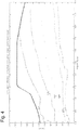
- the reason for the present invention being advantageous from a fuel consumption point of view is explained below with reference to Fig. 4 . It is to be understood that the present invention is applicable also for vehicles where the propulsion of the vehicle is accomplished by means of an electrical machine.
- solid lines of figs. 3A-E represent propulsion of the vehicle according to the present invention using an electrical machine, and where dashed lines represents propulsion using an electrical machine according to the prior art.
- Fig. 3E in this case, would represent energy consumption rather than fuel consumption.
- combustion efficiency An exemplary "combustion efficiency" map is shown in Fig. 4 .
- the y-axis represents produced torque and the x-axis represents engine speed.
- the various curves (0.47; 0.49; 0.51 etc.) represent efficiency levels where the higher the stated number, the higher the efficiency.
- combustion efficiency this can be defined as the efficiency of conversion of diesel energy to nominal mechanical energy in the engine, where nominal mechanical energy in this case is defined as the sum of measured mechanical energy of the flywheel and internal mechanical losses of the engine (e.g. friction and pump losses),
- lower torques result in higher overall efficiency in the propulsion of the vehicle 100.
- the present invention utilises the consequences of fig. 4 by keeping the torque constant to a higher extent and thereby at lower values in comparison to the situation where the torque is arranged to vary freely in order to maintain a constant speed.
- the present invention provides a solution that, at least in some situations, provides a method for propulsion of the vehicle that reduces the consumption of fuel.
- the vehicle 100 when a torque profile has been determined in step 203, the vehicle 100 can be arranged to be controlled according to the determined torque profile during the upcoming road segment, after which the method can be arranged to return to step 201, e.g. for determination of a torque profile of a next segment of road.
- a speed profile is calculated in step 204 based on the determined torque profile, where the estimated speed profile e.g. can be of the kind shown in Fig. 3C , in order to determine the maximum and/or minimum speeds that the vehicle will exhibit when being driven along the road segment according to the torque profile.
- the speed profile can be estimated in a manner similar to the above in a straightforward manner using the torque profile determined from step 203, estimated driving resistance and road topography.
- the speed profile can be used, for example, step 205, to determine if the maximum speed v max that the vehicle will reach during the road segment will exceed some speed limit v lim that the vehicle for some reason is not allowed to exceed. If this is the case, propulsion of the vehicle 100 according to the determined torque profile can be prohibited, or, alternatively, a new calculation can be performed e.g. for a shorter period of time and/or a shorter distance, e.g. by reducing the length of road segment by some suitable reduction factor, e.g. a percentage or segment length in terms of time, step 206, in order to determine if this would result in a speed profile that does not violate set criteria. According to one embodiment, it is determined, also or in the alternative, whether the minimum speed v min that the vehicle will exhibit during the road segment will go below some second speed limit v lim2 , and if so, the above measure with regard to the road segment can be taken.
- a conventional cruise control algorithm can be arranged to take precedence to ensure that the speed e.g. does not exceed set limits in such situations, that is, the conventional cruise control function can be arranged to override vehicle propulsion according to the present invention if the vehicle speed deviates from the allowed speed range.
- the allowed deviation in speed can, for example, be set to vary with the current vehicle speed. If the vehicle is being driven at higher speeds the negative impact of air resistance will be higher than the negative impact at lower speeds. Consequently, higher deviations, in particular with regard to increases in speed, can be allowed for comparatively lower speeds than comparatively higher speeds.
- estimation and simulation is performed for a number of lengths (measured in time or distance) of the road segment where, following simulation, propulsion of the vehicle can be controlled according to the results of the longest segment for which certain criterion or criteria, e.g. with regard to the resulting vehicle speed, is/are still fulfilled.
- propulsion of the vehicle can be controlled according to the results of the longest segment for which the estimated resulting vehicle speed does not exceed a maximum speed limit and/or does not fall below a minimum speed limit.
- Simulation can also be arranged to be performed for various torque levels, to determine a suitable level that fulfils the set criteria. For example, a first torque level can be used for a first part of the road segment, and a second torque level can be used for a second part of the road segment.
- Propulsion of the vehicle according to the present invention can further be arranged to take other restrictions into account.
- there may exist other modes of operation of the vehicle which, for certain types of road segments, are capable of reducing fuel consumption to a higher extent than being possible using the present invention. This can, for example, be the case with regard to downhill slopes where coasting, or free-wheeling, i.e. travelling with the combustion engine disconnected from the vehicle drive wheels, is advantageous.
- the propulsion of the vehicle according to the present invention can be used up to a point where coasting is preferable, which, for example, can be determined using a conventional look ahead cruise control function.
- the method according to the present invention can be arranged to ensure that the vehicle speed, when reaching the point at which coasting is to begin, corresponds to the vehicle speed that the vehicle would exhibit had it been driven according to the conventional cruise control function.
- the torque profile can then be determined such that the speed of the vehicle fulfils the desired condition at the desired position.
- a suitable compensation of the torque level to be used for the road segment can be performed, so that the vehicle speed at the end of the segment will correspond to the desired speed.
- the propulsion of the vehicle can be arranged to shift between cruise control strategies according to variations in the road along which the vehicle is travelling to benefit from different cruise control functions, where the particular cruise function that at present is most efficient can be used.
- the method according to the invention can be arranged to be repeated at any suitable interval, such as e.g. every second or more or less often, so that the determined torque can be adapted slightly if required in dependence of differences between estimations and actual measurement and/or differences in the road segment for which estimation is being performed.
- the present invention provides a solution where the method for propulsion of the vehicle strives to reduce variations in torque delivered by the combustion engine at the expense of increased variations in vehicle speed.
- the present invention has been exemplified for a combustion engine.
- the invention is, however, equally applicable for use in vehicles being at least partly powered by an electrical machine.
- the combination of electrical machines and drive trains in vehicles can exhibit similar characteristics with regard to energy consumption as has been described with regard to fuel consumption above. Consequently, the present invention can be utilized to reduce energy consumption also in vehicles completely or partly utilizing electrical machines.
Landscapes
- Engineering & Computer Science (AREA)
- Transportation (AREA)
- Mechanical Engineering (AREA)
- Automation & Control Theory (AREA)
- Chemical & Material Sciences (AREA)
- Combustion & Propulsion (AREA)
- Human Computer Interaction (AREA)
- Mathematical Physics (AREA)
- Physics & Mathematics (AREA)
- Control Of Driving Devices And Active Controlling Of Vehicle (AREA)
- Control Of Vehicle Engines Or Engines For Specific Uses (AREA)
- Electric Propulsion And Braking For Vehicles (AREA)
- Arrangement And Driving Of Transmission Devices (AREA)
- Controls For Constant Speed Travelling (AREA)
Claims (15)
- Verfahren zum Antrieb eines Fahrzeugs (100), wobei das Fahrzeug (100) zumindest eine Leistungsquelle (101) zum Liefern von Leistung an wenigstens ein Antriebsrad (113, 114) des Fahrzeugs (100) aufweist, wobei das Verfahren, wenn das Fahrzeug (100) entlang eines ersten Weges gefahren werden soll, umfasst:- bevor das Fahrzeug entlang eines ersten Teilstücks gefahren wird, Ermitteln eines Drehmomentprofils zur Verwendung beim Steuern der ersten Leistungsquelle (101) beim Fahren des Fahrzeugs (100) entlang wenigstens des ersten Teilstücks des ersten Weges (A-B),- Ermitteln des Drehmomentprofils auf der Basis einer geschätzten Repräsentation einer Drehmomentanforderung beim Fahren des Fahrzeugs (100) entlang des ersten Teilstücks,dadurch gekennzeichnet, dass- wenn das Drehmomentprofil ermittelt wird, Verringern von Schwankungen des von der Leistungsquelle (101) gelieferten Drehmoments durch Zulassen größerer Geschwindigkeitsabweichungen des Fahrzeugs (100),wenn das Drehmomentprofil ermittelt wird, Abschätzen einer mittleren Drehmomentanforderung beim Fahren des Fahrzeugs (100) entlang des ersten Teilstücks,- Ermitteln des Drehmomentprofils auf der Basis der abgeschätzten mittleren Drehmomentanforderung, und- wenn das Fahrzeug (100) entlang des ersten Teilstücks des ersten Weges gefahren wird, Steuern des von der zumindest einen Leistungsquelle gelieferten Drehmoments gemäß dem ermittelten Drehmomentprofil.
- Verfahren nach Anspruch 1, ferner umfassend:- Ermitteln des Drehmomentprofils im Wesentlichen als das abgeschätzte mittlere Drehmoment.
- Verfahren nach einem der Ansprüche 1 bis 2, ferner umfassend:- Ermitteln der Repräsentation einer Drehmomentanforderung beim Fahren des Fahrzeugs (100) entlang des ersten Teilstücks auf der Basis von Topographieinformation des ersten Teilstücks des ersten Weges.
- Verfahren nach einem der vorhergehenden Ansprüche, ferner umfassend:- Ermitteln des Drehmomentprofils, wenn das Fahrzeug (100) durch eine Fahrtregelungsfunktion gesteuert wird, die auf eine erste Geschwindigkeit eingestellt ist, und- wenn das Drehmomentprofil ermittelt wird, Verringern von Schwankungen des von der Leistungsquelle (101) gelieferten Drehmoments durch Zulassen größerer Abweichungen um die erste eingestellte Geschwindigkeit des Fahrzeugs (100).
- Verfahren nach einem der vorhergehenden Ansprüche, ferner umfassend:- Abschätzen einer maximalen und/oder einer minimalen Geschwindigkeit des Fahrzeugs beim Durchfahren des ersten Teilstücks, und- Steuern des von der zumindest einen Leistungsquelle gelieferten Drehmoments entsprechend dem ermittelten Drehmomentprofil nur dann, wenn die Maximalgeschwindigkeit unterhalb einer ersten Geschwindigkeitsbegrenzung (vlim) liegt und/oder die Minimalgeschwindigkeit oberhalb einer zweiten Geschwindigkeitsbegrenzung (vlim2) liegt.
- Verfahren nach einem der vorhergehenden Ansprüche, ferner umfassend:- Abschätzen der von der ersten Leistungsquelle (101) beim Fahren des Fahrzeugs (100) entlang des wenigstens ersten Teilstücks des ersten Weges zu liefernden Drehmomentanforderung für eine erste Fahrzeuggeschwindigkeit.
- Verfahren nach einem der Ansprüche 1 bis 5, ferner umfassend:- Abschätzen der Drehmomentanforderung beim Fahren des Fahrzeugs (100) entlang des ersten Teilstücks durch Simulieren des Fahrens des Fahrzeugs (100) entlang des ersten Teilstücks mit einer ersten Fahrzeuggeschwindigkeit.
- Verfahren nach Anspruch 6 oder 7, wobei die erste Fahrzeuggeschwindigkeit eine eingestellte Geschwindigkeit einer Fahrtregelungsfunktion und/oder eine von einem Fahrer des Fahrzeugs (100) eingestellte Geschwindigkeit ist.
- Verfahren nach einem der vorhergehenden Ansprüche, ferner umfassend:- Ermitteln des ersten Drehmomentprofils solchermaßen, dass die erste Leistungsquelle für zumindest einen Teil des ersten Teilstücks ein im Wesentlichen konstantes Drehmoment liefert.
- Verfahren nach einem der vorhergehenden Ansprüche, ferner umfassend:- Ermitteln des ersten Drehmomentprofils solchermaßen, dass die erste Leistungsquelle ein im Wesentlichen konstantes Drehmoment liefert, das zu der abgeschätzten Gesamtarbeit führt, wenn das Fahrzeug das erste Teilstück durchfährt.
- Verfahren nach einem der vorhergehenden Ansprüche, ferner umfassend:- Ermitteln des ersten Drehmomentprofils solchermaßen, dass die Drehmomentschwankungen während des ersten Teilstücks begrenzt sind auf: mittleres Drehmoment ± 20% oder mittleres Drehmoment ± 40%.
- Computerprogramm umfassend einen Programmcode, das, wenn der Programmcode auf einem Computer ausgeführt wird, den Computer veranlasst, das Verfahren nach einem der Ansprüche 1 bis 12 durchzuführen.
- Computerprogrammprodukt mit einem computerlesbaren Medium und einem Computerprogramm nach Anspruch 12, wobei das Computerprogramm in dem computerlesbaren Medium enthalten ist.
- System zum Antrieb eines Fahrzeugs (100), wobei das Fahrzeug (100) zumindest eine Leistungsquelle (101) zum Liefern von Leistung an wenigstens ein Antriebsrad (113, 114) des Fahrzeugs (100) aufweist, wobei das System Mittel aufweist zum, wenn das Fahrzeug (100) entlang eines ersten Weges gefahren werden soll:- bevor das Fahrzeug entlang eines ersten Teilstücks gefahren wird, Ermitteln eines Drehmomentprofils zur Verwendung beim Steuern der ersten Leistungsquelle (101) beim Fahren des Fahrzeugs (100) entlang wenigstens des ersten Teilstücks des ersten Weges (A-B),- Ermitteln des Drehmomentprofils auf der Basis einer geschätzten Repräsentation einer Drehmomentanforderung beim Fahren des Fahrzeugs (100) entlang des ersten Teilstücks,dadurch gekennzeichnet, dass- wenn das Drehmomentprofil ermittelt wird, Verringern von Schwankungen des von der Leistungsquelle (101) gelieferten Drehmoments durch Zulassen größerer Geschwindigkeitsabweichungen des Fahrzeugs (100),- wenn das Drehmomentprofil ermittelt wird, Abschätzen einer mittleren Drehmomentanforderung beim Fahren des Fahrzeugs (100) entlang des ersten Teilstücks,- Ermitteln des Drehmomentprofils auf der Basis der abgeschätzten mittleren Drehmomentanforderung, und- wenn das Fahrzeug (100) entlang des ersten Teilstücks des ersten Weges gefahren wird, Steuern des von der zumindest einen Leistungsquelle gelieferten Drehmoments gemäß dem ermittelten Drehmomentprofil.
- Fahrzeug, dadurch gekennzeichnet, dass es ein System nach Anspruch 14 enthält.
Applications Claiming Priority (2)
| Application Number | Priority Date | Filing Date | Title |
|---|---|---|---|
| SE1451252A SE539494C2 (en) | 2014-10-20 | 2014-10-20 | Method and system for propulsion of a vehicle |
| PCT/SE2015/051025 WO2016064327A1 (en) | 2014-10-20 | 2015-09-29 | Method and system for propulsion of a vehicle |
Publications (3)
| Publication Number | Publication Date |
|---|---|
| EP3209533A1 EP3209533A1 (de) | 2017-08-30 |
| EP3209533A4 EP3209533A4 (de) | 2018-07-04 |
| EP3209533B1 true EP3209533B1 (de) | 2019-11-20 |
Family
ID=55761229
Family Applications (1)
| Application Number | Title | Priority Date | Filing Date |
|---|---|---|---|
| EP15853493.3A Active EP3209533B1 (de) | 2014-10-20 | 2015-09-29 | Verfahren und system zum antrieb eines fahrzeuges |
Country Status (6)
| Country | Link |
|---|---|
| US (1) | US10421454B2 (de) |
| EP (1) | EP3209533B1 (de) |
| KR (1) | KR102069757B1 (de) |
| BR (1) | BR112017004804B1 (de) |
| SE (1) | SE539494C2 (de) |
| WO (1) | WO2016064327A1 (de) |
Families Citing this family (2)
| Publication number | Priority date | Publication date | Assignee | Title |
|---|---|---|---|---|
| US10661805B2 (en) * | 2016-11-22 | 2020-05-26 | Samsung Electronics Co., Ltd. | Vehicle control unit (VCU) and operating method thereof |
| CN107487324B (zh) * | 2017-06-22 | 2020-02-14 | 宝沃汽车(中国)有限公司 | 控制电动汽车转矩的方法和装置 |
Family Cites Families (12)
| Publication number | Priority date | Publication date | Assignee | Title |
|---|---|---|---|---|
| SE0801475L (sv) | 2008-06-23 | 2009-12-24 | Scania Cv Abp | Förfarande för motorstyrning |
| KR101021116B1 (ko) * | 2008-08-20 | 2011-03-14 | 기아자동차주식회사 | 하이브리드 차량의 모터 토크 제어 방법 |
| DE102009030784A1 (de) | 2009-06-27 | 2010-02-04 | Daimler Ag | Verfahren zum Steuern des Betriebs eines Fahrzeugs |
| US8346418B2 (en) * | 2009-11-30 | 2013-01-01 | GM Global Technology Operations LLC | Method of smoothing output torque |
| SE537307C2 (sv) * | 2010-04-23 | 2015-03-31 | Scania Cv Ab | Metod och system för att jämföra en bränsleförbrukning för ett hybridfordon med en bränsleförbrukning för ett motsvarande icke-hybridfordon |
| US8696517B2 (en) * | 2011-08-19 | 2014-04-15 | GM Global Technology Operations LLC | System and method of controlling crankshaft torque during a transmission shift with torque capacity-based torque reduction range selection |
| US10377379B2 (en) * | 2011-10-29 | 2019-08-13 | Robotic Research, Llc | Method and system for utilizing the energy storage provided by a vehicle's mass in the form of potential and kinetic energy to optimize fuel consumption |
| US9108639B2 (en) | 2011-12-22 | 2015-08-18 | Scania Cv Ab | Method and module for controlling a vehicle's speed based on rules and/or costs |
| SE536269C2 (sv) | 2011-12-22 | 2013-07-23 | Scania Cv Ab | En modul och en metod avseende modval vid bestämning av referensvärden |
| DE102012210317A1 (de) * | 2012-06-19 | 2013-12-19 | Robert Bosch Gmbh | Verfahren und Vorrichtung zum Fahren einer Fahrstrecke mit einem vorgegebenen gewünschten mittleren Energieverbrauch |
| KR20140112925A (ko) * | 2013-03-15 | 2014-09-24 | 주식회사 한라홀딩스 | 차량용 속도 조절 장치 및 그 속도 조절 방법 |
| WO2014149043A1 (en) | 2013-03-20 | 2014-09-25 | International Truck Intellectual Property Company, Llc | Smart cruise control system |
-
2014
- 2014-10-20 SE SE1451252A patent/SE539494C2/en unknown
-
2015
- 2015-09-29 US US15/513,013 patent/US10421454B2/en active Active
- 2015-09-29 WO PCT/SE2015/051025 patent/WO2016064327A1/en active Application Filing
- 2015-09-29 EP EP15853493.3A patent/EP3209533B1/de active Active
- 2015-09-29 BR BR112017004804-3A patent/BR112017004804B1/pt active IP Right Grant
- 2015-09-29 KR KR1020177012777A patent/KR102069757B1/ko active IP Right Grant
Non-Patent Citations (1)
| Title |
|---|
| None * |
Also Published As
| Publication number | Publication date |
|---|---|
| BR112017004804B1 (pt) | 2022-09-20 |
| SE1451252A1 (en) | 2016-04-21 |
| BR112017004804A2 (pt) | 2017-12-12 |
| KR20170070142A (ko) | 2017-06-21 |
| EP3209533A1 (de) | 2017-08-30 |
| US20170297572A1 (en) | 2017-10-19 |
| US10421454B2 (en) | 2019-09-24 |
| WO2016064327A1 (en) | 2016-04-28 |
| KR102069757B1 (ko) | 2020-01-23 |
| SE539494C2 (en) | 2017-10-03 |
| EP3209533A4 (de) | 2018-07-04 |
Similar Documents
| Publication | Publication Date | Title |
|---|---|---|
| RU2564066C2 (ru) | Способ и система для транспортного средства | |
| CN114312728B (zh) | 传动系脱离和滑行管理 | |
| CN109563782B (zh) | 控制发动机的操作的方法 | |
| KR101728084B1 (ko) | 차량의 실제 속도 제어 방법 | |
| RU2510474C1 (ru) | Способ и система для управления транспортным средством | |
| US8738252B2 (en) | Method and system for driving of a vehicle | |
| CN107792048A (zh) | 变矩器离合器接合压力 | |
| JP2014520703A (ja) | 車両の走行抵抗の決定 | |
| US20180170383A1 (en) | Method for controlling an actual speed of a motor vehicle | |
| EP2731843B1 (de) | Verfahren und vorrichtung zur bestimmung des energieverbrauchs von fahrzeugen | |
| EP3209533B1 (de) | Verfahren und system zum antrieb eines fahrzeuges | |
| SE540598C2 (en) | A method for controlling a powertrain of a motor vehicle | |
| KR101993434B1 (ko) | 차량의 준비 수단에 대한 제어 | |
| WO2017095309A1 (en) | Method and device for determining a measure of brake system usage during operation of a vehicle | |
| SE540825C2 (en) | A method and a system for controlling a powertrain of a vehicle | |
| CN114651143A (zh) | 用于控制车辆的变速器的方法 |
Legal Events
| Date | Code | Title | Description |
|---|---|---|---|
| STAA | Information on the status of an ep patent application or granted ep patent |
Free format text: STATUS: THE INTERNATIONAL PUBLICATION HAS BEEN MADE |
|
| PUAI | Public reference made under article 153(3) epc to a published international application that has entered the european phase |
Free format text: ORIGINAL CODE: 0009012 |
|
| STAA | Information on the status of an ep patent application or granted ep patent |
Free format text: STATUS: REQUEST FOR EXAMINATION WAS MADE |
|
| 17P | Request for examination filed |
Effective date: 20170522 |
|
| AK | Designated contracting states |
Kind code of ref document: A1 Designated state(s): AL AT BE BG CH CY CZ DE DK EE ES FI FR GB GR HR HU IE IS IT LI LT LU LV MC MK MT NL NO PL PT RO RS SE SI SK SM TR |
|
| AX | Request for extension of the european patent |
Extension state: BA ME |
|
| DAV | Request for validation of the european patent (deleted) | ||
| DAX | Request for extension of the european patent (deleted) | ||
| A4 | Supplementary search report drawn up and despatched |
Effective date: 20180605 |
|
| RIC1 | Information provided on ipc code assigned before grant |
Ipc: B60W 40/076 20120101ALI20180529BHEP Ipc: B60W 30/14 20060101AFI20180529BHEP Ipc: B60W 10/06 20060101ALI20180529BHEP Ipc: B60W 50/00 20060101ALI20180529BHEP Ipc: B60W 30/188 20120101ALI20180529BHEP |
|
| GRAP | Despatch of communication of intention to grant a patent |
Free format text: ORIGINAL CODE: EPIDOSNIGR1 |
|
| STAA | Information on the status of an ep patent application or granted ep patent |
Free format text: STATUS: GRANT OF PATENT IS INTENDED |
|
| INTG | Intention to grant announced |
Effective date: 20190618 |
|
| GRAS | Grant fee paid |
Free format text: ORIGINAL CODE: EPIDOSNIGR3 |
|
| GRAA | (expected) grant |
Free format text: ORIGINAL CODE: 0009210 |
|
| STAA | Information on the status of an ep patent application or granted ep patent |
Free format text: STATUS: THE PATENT HAS BEEN GRANTED |
|
| AK | Designated contracting states |
Kind code of ref document: B1 Designated state(s): AL AT BE BG CH CY CZ DE DK EE ES FI FR GB GR HR HU IE IS IT LI LT LU LV MC MK MT NL NO PL PT RO RS SE SI SK SM TR |
|
| REG | Reference to a national code |
Ref country code: GB Ref legal event code: FG4D |
|
| REG | Reference to a national code |
Ref country code: CH Ref legal event code: EP |
|
| REG | Reference to a national code |
Ref country code: IE Ref legal event code: FG4D |
|
| REG | Reference to a national code |
Ref country code: DE Ref legal event code: R096 Ref document number: 602015042276 Country of ref document: DE |
|
| REG | Reference to a national code |
Ref country code: AT Ref legal event code: REF Ref document number: 1203849 Country of ref document: AT Kind code of ref document: T Effective date: 20191215 |
|
| REG | Reference to a national code |
Ref country code: NL Ref legal event code: MP Effective date: 20191120 |
|
| REG | Reference to a national code |
Ref country code: LT Ref legal event code: MG4D |
|
| PG25 | Lapsed in a contracting state [announced via postgrant information from national office to epo] |
Ref country code: LT Free format text: LAPSE BECAUSE OF FAILURE TO SUBMIT A TRANSLATION OF THE DESCRIPTION OR TO PAY THE FEE WITHIN THE PRESCRIBED TIME-LIMIT Effective date: 20191120 Ref country code: NO Free format text: LAPSE BECAUSE OF FAILURE TO SUBMIT A TRANSLATION OF THE DESCRIPTION OR TO PAY THE FEE WITHIN THE PRESCRIBED TIME-LIMIT Effective date: 20200220 Ref country code: GR Free format text: LAPSE BECAUSE OF FAILURE TO SUBMIT A TRANSLATION OF THE DESCRIPTION OR TO PAY THE FEE WITHIN THE PRESCRIBED TIME-LIMIT Effective date: 20200221 Ref country code: NL Free format text: LAPSE BECAUSE OF FAILURE TO SUBMIT A TRANSLATION OF THE DESCRIPTION OR TO PAY THE FEE WITHIN THE PRESCRIBED TIME-LIMIT Effective date: 20191120 Ref country code: BG Free format text: LAPSE BECAUSE OF FAILURE TO SUBMIT A TRANSLATION OF THE DESCRIPTION OR TO PAY THE FEE WITHIN THE PRESCRIBED TIME-LIMIT Effective date: 20200220 Ref country code: FI Free format text: LAPSE BECAUSE OF FAILURE TO SUBMIT A TRANSLATION OF THE DESCRIPTION OR TO PAY THE FEE WITHIN THE PRESCRIBED TIME-LIMIT Effective date: 20191120 Ref country code: LV Free format text: LAPSE BECAUSE OF FAILURE TO SUBMIT A TRANSLATION OF THE DESCRIPTION OR TO PAY THE FEE WITHIN THE PRESCRIBED TIME-LIMIT Effective date: 20191120 Ref country code: SE Free format text: LAPSE BECAUSE OF FAILURE TO SUBMIT A TRANSLATION OF THE DESCRIPTION OR TO PAY THE FEE WITHIN THE PRESCRIBED TIME-LIMIT Effective date: 20191120 |
|
| PG25 | Lapsed in a contracting state [announced via postgrant information from national office to epo] |
Ref country code: HR Free format text: LAPSE BECAUSE OF FAILURE TO SUBMIT A TRANSLATION OF THE DESCRIPTION OR TO PAY THE FEE WITHIN THE PRESCRIBED TIME-LIMIT Effective date: 20191120 Ref country code: IS Free format text: LAPSE BECAUSE OF FAILURE TO SUBMIT A TRANSLATION OF THE DESCRIPTION OR TO PAY THE FEE WITHIN THE PRESCRIBED TIME-LIMIT Effective date: 20200320 Ref country code: RS Free format text: LAPSE BECAUSE OF FAILURE TO SUBMIT A TRANSLATION OF THE DESCRIPTION OR TO PAY THE FEE WITHIN THE PRESCRIBED TIME-LIMIT Effective date: 20191120 |
|
| PG25 | Lapsed in a contracting state [announced via postgrant information from national office to epo] |
Ref country code: AL Free format text: LAPSE BECAUSE OF FAILURE TO SUBMIT A TRANSLATION OF THE DESCRIPTION OR TO PAY THE FEE WITHIN THE PRESCRIBED TIME-LIMIT Effective date: 20191120 |
|
| PG25 | Lapsed in a contracting state [announced via postgrant information from national office to epo] |
Ref country code: ES Free format text: LAPSE BECAUSE OF FAILURE TO SUBMIT A TRANSLATION OF THE DESCRIPTION OR TO PAY THE FEE WITHIN THE PRESCRIBED TIME-LIMIT Effective date: 20191120 Ref country code: CZ Free format text: LAPSE BECAUSE OF FAILURE TO SUBMIT A TRANSLATION OF THE DESCRIPTION OR TO PAY THE FEE WITHIN THE PRESCRIBED TIME-LIMIT Effective date: 20191120 Ref country code: PT Free format text: LAPSE BECAUSE OF FAILURE TO SUBMIT A TRANSLATION OF THE DESCRIPTION OR TO PAY THE FEE WITHIN THE PRESCRIBED TIME-LIMIT Effective date: 20200412 Ref country code: RO Free format text: LAPSE BECAUSE OF FAILURE TO SUBMIT A TRANSLATION OF THE DESCRIPTION OR TO PAY THE FEE WITHIN THE PRESCRIBED TIME-LIMIT Effective date: 20191120 Ref country code: DK Free format text: LAPSE BECAUSE OF FAILURE TO SUBMIT A TRANSLATION OF THE DESCRIPTION OR TO PAY THE FEE WITHIN THE PRESCRIBED TIME-LIMIT Effective date: 20191120 Ref country code: EE Free format text: LAPSE BECAUSE OF FAILURE TO SUBMIT A TRANSLATION OF THE DESCRIPTION OR TO PAY THE FEE WITHIN THE PRESCRIBED TIME-LIMIT Effective date: 20191120 |
|
| REG | Reference to a national code |
Ref country code: AT Ref legal event code: MK05 Ref document number: 1203849 Country of ref document: AT Kind code of ref document: T Effective date: 20191120 |
|
| REG | Reference to a national code |
Ref country code: DE Ref legal event code: R097 Ref document number: 602015042276 Country of ref document: DE |
|
| PG25 | Lapsed in a contracting state [announced via postgrant information from national office to epo] |
Ref country code: SK Free format text: LAPSE BECAUSE OF FAILURE TO SUBMIT A TRANSLATION OF THE DESCRIPTION OR TO PAY THE FEE WITHIN THE PRESCRIBED TIME-LIMIT Effective date: 20191120 Ref country code: SM Free format text: LAPSE BECAUSE OF FAILURE TO SUBMIT A TRANSLATION OF THE DESCRIPTION OR TO PAY THE FEE WITHIN THE PRESCRIBED TIME-LIMIT Effective date: 20191120 |
|
| PLBE | No opposition filed within time limit |
Free format text: ORIGINAL CODE: 0009261 |
|
| STAA | Information on the status of an ep patent application or granted ep patent |
Free format text: STATUS: NO OPPOSITION FILED WITHIN TIME LIMIT |
|
| 26N | No opposition filed |
Effective date: 20200821 |
|
| PG25 | Lapsed in a contracting state [announced via postgrant information from national office to epo] |
Ref country code: AT Free format text: LAPSE BECAUSE OF FAILURE TO SUBMIT A TRANSLATION OF THE DESCRIPTION OR TO PAY THE FEE WITHIN THE PRESCRIBED TIME-LIMIT Effective date: 20191120 Ref country code: PL Free format text: LAPSE BECAUSE OF FAILURE TO SUBMIT A TRANSLATION OF THE DESCRIPTION OR TO PAY THE FEE WITHIN THE PRESCRIBED TIME-LIMIT Effective date: 20191120 Ref country code: SI Free format text: LAPSE BECAUSE OF FAILURE TO SUBMIT A TRANSLATION OF THE DESCRIPTION OR TO PAY THE FEE WITHIN THE PRESCRIBED TIME-LIMIT Effective date: 20191120 |
|
| PG25 | Lapsed in a contracting state [announced via postgrant information from national office to epo] |
Ref country code: IT Free format text: LAPSE BECAUSE OF FAILURE TO SUBMIT A TRANSLATION OF THE DESCRIPTION OR TO PAY THE FEE WITHIN THE PRESCRIBED TIME-LIMIT Effective date: 20191120 |
|
| REG | Reference to a national code |
Ref country code: CH Ref legal event code: PL |
|
| GBPC | Gb: european patent ceased through non-payment of renewal fee |
Effective date: 20200929 |
|
| REG | Reference to a national code |
Ref country code: BE Ref legal event code: MM Effective date: 20200930 |
|
| PG25 | Lapsed in a contracting state [announced via postgrant information from national office to epo] |
Ref country code: LU Free format text: LAPSE BECAUSE OF NON-PAYMENT OF DUE FEES Effective date: 20200929 |
|
| PG25 | Lapsed in a contracting state [announced via postgrant information from national office to epo] |
Ref country code: FR Free format text: LAPSE BECAUSE OF NON-PAYMENT OF DUE FEES Effective date: 20200930 |
|
| PG25 | Lapsed in a contracting state [announced via postgrant information from national office to epo] |
Ref country code: IE Free format text: LAPSE BECAUSE OF NON-PAYMENT OF DUE FEES Effective date: 20200929 Ref country code: LI Free format text: LAPSE BECAUSE OF NON-PAYMENT OF DUE FEES Effective date: 20200930 Ref country code: GB Free format text: LAPSE BECAUSE OF NON-PAYMENT OF DUE FEES Effective date: 20200929 Ref country code: BE Free format text: LAPSE BECAUSE OF NON-PAYMENT OF DUE FEES Effective date: 20200930 Ref country code: CH Free format text: LAPSE BECAUSE OF NON-PAYMENT OF DUE FEES Effective date: 20200930 |
|
| PG25 | Lapsed in a contracting state [announced via postgrant information from national office to epo] |
Ref country code: TR Free format text: LAPSE BECAUSE OF FAILURE TO SUBMIT A TRANSLATION OF THE DESCRIPTION OR TO PAY THE FEE WITHIN THE PRESCRIBED TIME-LIMIT Effective date: 20191120 Ref country code: MT Free format text: LAPSE BECAUSE OF FAILURE TO SUBMIT A TRANSLATION OF THE DESCRIPTION OR TO PAY THE FEE WITHIN THE PRESCRIBED TIME-LIMIT Effective date: 20191120 Ref country code: CY Free format text: LAPSE BECAUSE OF FAILURE TO SUBMIT A TRANSLATION OF THE DESCRIPTION OR TO PAY THE FEE WITHIN THE PRESCRIBED TIME-LIMIT Effective date: 20191120 |
|
| PG25 | Lapsed in a contracting state [announced via postgrant information from national office to epo] |
Ref country code: MK Free format text: LAPSE BECAUSE OF FAILURE TO SUBMIT A TRANSLATION OF THE DESCRIPTION OR TO PAY THE FEE WITHIN THE PRESCRIBED TIME-LIMIT Effective date: 20191120 Ref country code: MC Free format text: LAPSE BECAUSE OF FAILURE TO SUBMIT A TRANSLATION OF THE DESCRIPTION OR TO PAY THE FEE WITHIN THE PRESCRIBED TIME-LIMIT Effective date: 20191120 |
|
| P01 | Opt-out of the competence of the unified patent court (upc) registered |
Effective date: 20230518 |
|
| PGFP | Annual fee paid to national office [announced via postgrant information from national office to epo] |
Ref country code: DE Payment date: 20230802 Year of fee payment: 9 |