EP2096491A2 - Teilchen für ein anzeigemedium - Google Patents
Teilchen für ein anzeigemedium Download PDFInfo
- Publication number
- EP2096491A2 EP2096491A2 EP07832879A EP07832879A EP2096491A2 EP 2096491 A2 EP2096491 A2 EP 2096491A2 EP 07832879 A EP07832879 A EP 07832879A EP 07832879 A EP07832879 A EP 07832879A EP 2096491 A2 EP2096491 A2 EP 2096491A2
- Authority
- EP
- European Patent Office
- Prior art keywords
- particles
- display media
- charge control
- charge
- display
- Prior art date
- Legal status (The legal status is an assumption and is not a legal conclusion. Google has not performed a legal analysis and makes no representation as to the accuracy of the status listed.)
- Withdrawn
Links
Images



Classifications
-
- G—PHYSICS
- G02—OPTICS
- G02F—OPTICAL DEVICES OR ARRANGEMENTS FOR THE CONTROL OF LIGHT BY MODIFICATION OF THE OPTICAL PROPERTIES OF THE MEDIA OF THE ELEMENTS INVOLVED THEREIN; NON-LINEAR OPTICS; FREQUENCY-CHANGING OF LIGHT; OPTICAL LOGIC ELEMENTS; OPTICAL ANALOGUE/DIGITAL CONVERTERS
- G02F1/00—Devices or arrangements for the control of the intensity, colour, phase, polarisation or direction of light arriving from an independent light source, e.g. switching, gating or modulating; Non-linear optics
- G02F1/01—Devices or arrangements for the control of the intensity, colour, phase, polarisation or direction of light arriving from an independent light source, e.g. switching, gating or modulating; Non-linear optics for the control of the intensity, phase, polarisation or colour
- G02F1/165—Devices or arrangements for the control of the intensity, colour, phase, polarisation or direction of light arriving from an independent light source, e.g. switching, gating or modulating; Non-linear optics for the control of the intensity, phase, polarisation or colour based on translational movement of particles in a fluid under the influence of an applied field
- G02F1/166—Devices or arrangements for the control of the intensity, colour, phase, polarisation or direction of light arriving from an independent light source, e.g. switching, gating or modulating; Non-linear optics for the control of the intensity, phase, polarisation or colour based on translational movement of particles in a fluid under the influence of an applied field characterised by the electro-optical or magneto-optical effect
- G02F1/167—Devices or arrangements for the control of the intensity, colour, phase, polarisation or direction of light arriving from an independent light source, e.g. switching, gating or modulating; Non-linear optics for the control of the intensity, phase, polarisation or colour based on translational movement of particles in a fluid under the influence of an applied field characterised by the electro-optical or magneto-optical effect by electrophoresis
-
- G—PHYSICS
- G02—OPTICS
- G02F—OPTICAL DEVICES OR ARRANGEMENTS FOR THE CONTROL OF LIGHT BY MODIFICATION OF THE OPTICAL PROPERTIES OF THE MEDIA OF THE ELEMENTS INVOLVED THEREIN; NON-LINEAR OPTICS; FREQUENCY-CHANGING OF LIGHT; OPTICAL LOGIC ELEMENTS; OPTICAL ANALOGUE/DIGITAL CONVERTERS
- G02F1/00—Devices or arrangements for the control of the intensity, colour, phase, polarisation or direction of light arriving from an independent light source, e.g. switching, gating or modulating; Non-linear optics
- G02F1/01—Devices or arrangements for the control of the intensity, colour, phase, polarisation or direction of light arriving from an independent light source, e.g. switching, gating or modulating; Non-linear optics for the control of the intensity, phase, polarisation or colour
- G02F1/165—Devices or arrangements for the control of the intensity, colour, phase, polarisation or direction of light arriving from an independent light source, e.g. switching, gating or modulating; Non-linear optics for the control of the intensity, phase, polarisation or colour based on translational movement of particles in a fluid under the influence of an applied field
- G02F1/1675—Constructional details
-
- G—PHYSICS
- G02—OPTICS
- G02F—OPTICAL DEVICES OR ARRANGEMENTS FOR THE CONTROL OF LIGHT BY MODIFICATION OF THE OPTICAL PROPERTIES OF THE MEDIA OF THE ELEMENTS INVOLVED THEREIN; NON-LINEAR OPTICS; FREQUENCY-CHANGING OF LIGHT; OPTICAL LOGIC ELEMENTS; OPTICAL ANALOGUE/DIGITAL CONVERTERS
- G02F1/00—Devices or arrangements for the control of the intensity, colour, phase, polarisation or direction of light arriving from an independent light source, e.g. switching, gating or modulating; Non-linear optics
- G02F1/01—Devices or arrangements for the control of the intensity, colour, phase, polarisation or direction of light arriving from an independent light source, e.g. switching, gating or modulating; Non-linear optics for the control of the intensity, phase, polarisation or colour
- G02F1/165—Devices or arrangements for the control of the intensity, colour, phase, polarisation or direction of light arriving from an independent light source, e.g. switching, gating or modulating; Non-linear optics for the control of the intensity, phase, polarisation or colour based on translational movement of particles in a fluid under the influence of an applied field
- G02F1/1675—Constructional details
- G02F1/1679—Gaskets; Spacers; Sealing of cells; Filling or closing of cells
-
- G—PHYSICS
- G02—OPTICS
- G02F—OPTICAL DEVICES OR ARRANGEMENTS FOR THE CONTROL OF LIGHT BY MODIFICATION OF THE OPTICAL PROPERTIES OF THE MEDIA OF THE ELEMENTS INVOLVED THEREIN; NON-LINEAR OPTICS; FREQUENCY-CHANGING OF LIGHT; OPTICAL LOGIC ELEMENTS; OPTICAL ANALOGUE/DIGITAL CONVERTERS
- G02F1/00—Devices or arrangements for the control of the intensity, colour, phase, polarisation or direction of light arriving from an independent light source, e.g. switching, gating or modulating; Non-linear optics
- G02F1/01—Devices or arrangements for the control of the intensity, colour, phase, polarisation or direction of light arriving from an independent light source, e.g. switching, gating or modulating; Non-linear optics for the control of the intensity, phase, polarisation or colour
- G02F1/165—Devices or arrangements for the control of the intensity, colour, phase, polarisation or direction of light arriving from an independent light source, e.g. switching, gating or modulating; Non-linear optics for the control of the intensity, phase, polarisation or colour based on translational movement of particles in a fluid under the influence of an applied field
- G02F1/1675—Constructional details
- G02F2001/1678—Constructional details characterised by the composition or particle type
Definitions
- an information display panel in which the display media having optical reflectance and charge characteristics are sealed between two substrates, at least one substrate being transparent, and, in which the display media, to which an electrostatic field is applied, are made to move so as to display information such as an image.
- the display media are moved by an electrostatic field so as to display information such as an image
- a particle diameter of the display media is about 1 - 50 ⁇ m
- the present invention has for its object to provide particles for display media which obtain a good charge amount necessary for maintaining a display quality and obtain an excellent heat resistance, by setting a blending amount of monomer with charged functional group in raw material monomer constituting charge control resins within a range in which resolvability into the monomer for binder resins, suspension stability and heat resistance become preferable respectively.
- an electrostatic field is applied to display media sealed in the space between two opposed substrates.
- the charged display media are attracted and moved by varying a direction of electrostatic field. Accordingly, information such as an image or the like can be displayed. Therefore, it is necessary to design the information display panel in such a manner that the display media can move evenly and maintain stability during a reciprocal operation or during a reserving state.
- forces applied to the particles constituting display media there are an attraction force between the particles due to Coulomb' force, an imaging force with respect to the electrodes or substrates, an intermolecular force, a liquid bonding force, a gravity and the like.
- a cell is formed by arranging for example grid-like partition walls 4 between the substrates 1 and 2, in addition to the example shown in Fig. 1a .
- the partition walls arranged at the near side are omitted.
- the polymerizable monomer means a chemical compound wherein a polymerization process can be performed, and examples of the polymerizable monomer include monovinyl monomer, cross-linkable monomer and so on. In the present invention, it is preferable to use monovinyl monomer as a main ingredient of the polymerizable monomer.
- the monovinyl monomer and the cross-linkable monomer it is preferable to use both of the monovinyl monomer and the cross-linkable monomer and it is more preferable to set a weight ratio of monovinyl monomer : cross-linkable monomer to 85:15 - 35:65.
- inorganic compounds such as inorganic hydroxide as the dispersion initiator
- washing method it is preferable to use a method in which the dispersion stabilizers are removed by dissolving them into a water by means of an addition of acid or alkali into the water dispersions of the polymer particles.
- colloid of poorly water soluble inorganic hydroxide as the dispersion stabilizers, it is preferable to control pH of the water dispersions of the polymer particles in a range not greater than 6.5.
- the acid to be added use may be made of inorganic acids such as sulfuric acid, hydrochloric acid, nitric acid and so on, or, organic acids such as formic acid, acetic acid and so on. Among them, it is especially preferable to use sulfuric acid since it has a large removing efficiency and a small burden for a production equipment.
- inorganic acids such as sulfuric acid, hydrochloric acid, nitric acid and so on
- organic acids such as formic acid, acetic acid and so on.
- sulfuric acid it is especially preferable to use sulfuric acid since it has a large removing efficiency and a small burden for a production equipment.
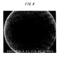
- the polymer particles used as the particles for display media it is preferable to use the polymer particles having a sphericity (Sc/Sr) of 1.00 - 1.30, and it is more preferable to use the polymer particles having a sphericity (Sc/Sr) of 1.00 - 1.20. If the sphericity (Sc/Sr) exceeds 1.30, a fluidity of the display media constituted by the particles for display media becomes lowered, and thus it becomes sometimes an obstacle for the movement as the particles for display media.
- the sphericity (Sc/Sr) of the polymer particles can be measured as mentioned below.
- the substrate As the substrate, at least one of the substrates is the transparent substrate through which a color of the display media can be observed from outside of the panel, and it is preferred to use a material having a high transmission factor of visible light and an excellent heat resistance.
- the other substrate may be transparent or may be opaque.
- the substrate material include polymer sheets such as polyethylene terephthalate (PET), polyethylene naphthalate (PEN), polyethylene (PE), polycarbonate (PC), polyimide (PI), polyether sulfone or acryl and metal sheets having flexibility and inorganic sheets such as glass, quartz or so having no flexibility.
- the thickness of the substrate is preferably 2 to 5000 ⁇ m, more preferably 5 to 2000 ⁇ m. When the thickness is too thin, it becomes difficult to maintain strength and distance uniformity between the substrates, and when the thickness is thicker than 5000 ⁇ m, there is a drawback as a thin-type information display panel.
- an electrode forming method use is made of a method in which the materials mentioned above are made to a thin film to perform pattering by means of sputtering method, vacuum vapor deposition method, CVD (chemical vapor deposition) method, coating method and so on, or, a method in which conductive materials and solvents are mixed with synthetic resin binder and the mixture is sprayed to perform pattering.
- a transparency is necessary for the electrode arranged to the substrate at an observation side (display surface side), but it is not necessary for the electrode arranged to the substrate at a rear side.
- the materials mentioned above which are conductive and have a pattern formation capability, can be suitably used.
- the thickness of the electrode may be suitable unless the electro-conductivity is absent or any hindrance exists in optical transparency, and it is preferable to be 0.01 to 10 ⁇ m, more preferable to be 0.05 to 5 ⁇ m.
- the material and the thickness of the electrode arranged to the rear substrate are the same as those of the electrode arranged to the substrate at the display side, but transparency is not necessary. In this case, the applied outer voltage may be superimposed with a direct current or an alternate current.
- a shape of the partition wall is suitably designed in accordance with a kind of the display media used for the display and is not restricted. However, it is preferred to set a width of the partition wall to 2 - 100 ⁇ m more preferably 3 - 50 ⁇ m and to set a height of the partition wall to 10 - 500 ⁇ m more preferably 10 - 200 ⁇ m.
- a method of forming the partition wall use may be made of a double rib method wherein ribs are formed on the opposed substrates 1, 2 respectively and they are connected with each other and a single rib method wherein a rib is formed on one of the opposed substrates only.
- the present invention may be preferably applied to both methods mentioned above.
- the cell formed by the partition walls each made of rib has a square shape, a triangular shape, a line shape, a circular shape and a hexagon shape, and has an arrangement such as a grid, a honeycomb and a mesh, as shown in Fig. 5 viewed from a plane surface of the substrate. It is preferred that the portion corresponding to a cross section of the partition wall observed from the display side (an area of the frame portion of the cell) should be made as small as possible. In this case, a clearness of the image display can be improved.
- the blow-off method a mixture of the particles and the carriers are placed into a cylindrical container with nets at both ends, and high-pressure gas is blown from the one end to separate the powders and the carriers, and then only the powders are blown off from the mesh of the net.
- charge amount of reverse blown polarity remains on the carriers with the same charge amount of the powders carried away out of the container.
- the display media constituted by the particles for display media are driven in an air space
- a gas control contributes an improvement of display stability.
- a humidity of the gap gas to not more than 60% RH at 25°C, preferably not more than 50% RH.
- the above gap means a gas portion surrounding the display media obtained by substituting the electrodes 5, 6 (in the case of arranging electrode inside of substrate), an occupied portion of the display media 3, an occupied portion of the partition walls 4 (in the case of arranging partition walls) and a seal portion of the device from the space between the substrate 1 and the substrate 2 for example in Figs.
- the obtained charge control resins for positive charge 1 has a weight-average molecular weight of 1.2 ⁇ 10 4 and a glass transition temperature of 67 °C.
- the obtained charge control resins for positive charge 2 has a weight-average molecular weight of 1.1 ⁇ 10 4 and a glass transition temperature of 66 °C.
- charge control resins for positive charge 100 parts by weight of polymerizable monomer including styrene 72.81 % (84.0 mol%), butyl acrylate 11.73 % (11.0 mol%) and N,N - diethyl - N - methyl - N - (2-methacryloyloxy) ethyl ammonium p - toluenesulfonate 15.46 % (5.0 mol%) were injected in a mixing solvent of 500 parts by weight of toluene and 400 parts by weight of methanol and were reacted at 80 °C for 8 hours in the presence of 4 parts by weight of 2,2' - azobis dimethyl valeronytril.
- charge control resins for positive charge 100 parts by weight of polymerizable monomer including styrene 38.39 % (64.0 mol%), butyl acrylate 8.12 % (11.0 mol%) and N,N - diethyl - N - methyl - N - (2-methacryloyloxy) ethyl ammonium p - toluenesulfonate 53.49 % (25.0 mol%) were injected in a mixing solvent of 500 parts by weight of toluene and 400 parts by weight of methanol and were reacted at 80 °C for 8 hours in the presence of 4 parts by weight of 2,2' - azobis dimethyl valeronytril.
- charge control resins for positive charge 100 parts by weight of polymerizable monomer including styrene 13.95 % (34.0 mol%), butyl acrylate 5.55 % (11.0 mol%) and N,N - diethyl - N - methyl - N - (2-methacryloyloxy) ethyl ammonium p - toluenesulfonate 80.50 % (55.0 mol%) were injected in a mixing solvent of 500 parts by weight of toluene and 400 parts by weight of methanol and were reacted at 80 °C for 8 hours in the presence of 4 parts by weight of 2,2' - azobis dimethyl valeronytril.
- charge control resins for positive charge 100 parts by weight of polymerizable monomer including styrene 86.31 % (88.7 mol%), butyl acrylate 13.17 % (11.0 mol%) and diethylaminoethyl methacylate 0.52 % (0.3 mol%) were injected in a mixing solvent of 500 parts by weight of toluene and 400 parts by weight of methanol and were reacted at 80 °C for 8 hours in the presence of 4 parts by weight of 2,2' - azobis dimethyl valeronytril.
- polymerizable monomer including styrene 86.31 % (88.7 mol%), butyl acrylate 13.17 % (11.0 mol%) and diethylaminoethyl methacylate 0.52 % (0.3 mol%) were injected in a mixing solvent of 500 parts by weight of toluene and 400 parts by weight of methanol and were reacted at 80 °C for 8 hours
- charge control resins for negative charge 1 copolymer including sulfonic acid (hereinafter, referred to charge control resins for negative charge 1) was obtained.
- the obtained charge control resins for negative charge 1 has a weight-average molecular weight of 1.4 ⁇ 10 4 and a glass transition temperature of 67 °C.
- charge control resins for negative charge 100 parts by weight of polymerizable monomer including styrene 86.25 % (88.7 mol%), butyl acrylate 13.17 % (11.0 mol%) and 2 - acrylamide - 2 - methylpropanesulfonic acid 0.58 % (0.3 mol%) were injected in a mixing solvent of 500 parts by weight of toluene and 400 parts by weight of methanol and were reacted at 80 °C for 8 hours in the presence of 4 parts by weight of 2,2' - azobis dimethyl valeronytril.
- polymerizable monomer including styrene 86.25 % (88.7 mol%), butyl acrylate 13.17 % (11.0 mol%) and 2 - acrylamide - 2 - methylpropanesulfonic acid 0.58 % (0.3 mol%) were injected in a mixing solvent of 500 parts by weight of toluene and 400 parts by weight of methanol and
- the obtained charge control resins for negative charge 3 has a weight-average molecular weight of 1.3 ⁇ 10 4 and a glass transition temperature of 64 °C.
- the obtained charge control resins for negative charge 4 has a weight-average molecular weight of 1.2 ⁇ 10 4 and a glass transition temperature of 63 °C.
- charge control resins for negative charge 100 parts by weight of polymerizable monomer including styrene 25.65 % (39.0 mol%), butyl acrylate 8.90 % (11.0 mol%) and 2 - acrylamide - 2 - methylpropanesulfonic acid 65.44 % (50.0 mol%) were injected in a mixing solvent of 500 parts by weight of toluene and 400 parts by weight of methanol and were reacted at 80 °C for 8 hours in the presence of 4 parts by weight of 2,2' - azobis dimethyl valeronytril.
- the obtained charge control resins for negative charge 5 has a weight-average molecular weight of 1.2 ⁇ 10 4 and a glass transition temperature of 62 °C.
- the obtained charge control resins for negative charge 6 has a weight-average molecular weight of 1.2 ⁇ 10 4 and a glass transition temperature of 62 °C.
- the mixed solution of the polymerizable monomer composite was injected into the colloid dispersion liquid of magnesium hydroxide obtained in the manner as mentioned above, and the agitation was performed until the droplet became stable. Then, 3 parts by weight of polymerization initiator: t - butylperoxy - 2 - ethylhexanoate (NOF CORPORATION, produce name "PERBUTYL O”) were added therein, and then the droplets of monomer mixture were formed by agitating in a highly sharing manner for 30 minutes by means of EBARAMILDER (EBARA CORPORATIN, produce name "MDN303V”) rotated at 15,000 rpm.
- EBARAMILDER EBARA CORPORATIN, produce name "MDN303V
- a glass transition temperature (Tg) of the binder resins only of the particles 1 was not observed due to a highly cross-linking state.
- a heat resistance test was performed with respect to the particles 1 after the particles 1 were maintained at 60 °C for one week. As a result, since a large amount of the charge control resins having a low heat resistance was blended therein, the particles were fused with each other.
- a blending amount of the negatively charged charge control resins 1 necessary for obtaining a charge amount (about - 20 ⁇ C/g) suitable as the particles for display media for the information display panel was 6 parts by weight.
- a glass transition temperature (Tg) of the binder resins only of the particles 2 was not observed due to a highly cross-linking state.
- a heat resistance test was performed with respect to the particles 2 after the particles 1 were maintained at 60 °C for one week. As a result, since a large amount of the charge control resins having a low heat resistance was blended therein, the particles were fused with each other.
- white particles 4 having an average volume particle diameter of 9.5 ⁇ m were obtained in the same manner as that of the particles 2 except that the charge control resins for negative charge 1 were changed to the charge control resins for negative charge 2 with respect to the particles 2 mentioned above.
- the average volume particle diameter was measured by Mastersizer 2000 (Malvern Instruments Ltd.).
- a blending amount of the negatively charged charge control resins 2 necessary for obtaining a charge amount (about - 20 ⁇ C/g) suitable as the particles for display media for the information display panel was 4.8 parts by weight.
- a glass transition temperature (Tg) of the binder resins only of the particles 4 was not observed due to a highly cross-linking state.
- a heat resistance test was performed with respect to the particles 5 after the particles 5 were maintained at 60 °C for one week. As a result, since the particles were not fused with each other, the particles having a high heat resistance and an excellent charge amount necessary for maintaining a display quality could be obtained.
- a heat resistance test was performed with respect to the particles 6 after the particles 6 were maintained at 60 °C for one week. As a result, since the particles were not fused with each other, the particles having a high heat resistance and an excellent charge amount necessary for maintaining a display quality could be obtained.
- white particles 8 having an average volume particle diameter of 9.2 ⁇ m were obtained in the same manner as that of the particles 2 except that the charge control resins for negative charge 1 were changed to the charge control resins for negative charge 4 with respect to the particles 2 mentioned above.
- the average volume particle diameter was measured by Mastersizer 2000 (Malvern Instruments Ltd.).
- a blending amount of the negatively charged charge control resins 5 necessary for obtaining a charge amount (about - 20 ⁇ C/g) suitable as the particles for display media for the information display panel was 1.0 parts by weight.
- a glass transition temperature (Tg) of the binder resins only of the particles 8 was not observed due to a highly cross-linking state.
- a heat resistance test was performed with respect to the particles 9 after the particles 9 were maintained at 60 °C for one week. As a result, since the particles were not fused with each other, the particles having a high heat resistance and an excellent charge amount necessary for maintaining a display quality could be obtained.
- black particles 13 having an average volume particle diameter of 9.0 ⁇ m were obtained in the same manner as that of the particles 1 except that 15 parts by weight of ethylene glycol dimethacrylate were changed to 5 parts by weight, 10 parts by weight of butyl acrylate were further added and the charge control resins for positive charge 1 were changed to the charge control resins for positive charge 4 with respect to the particles 1 mentioned above.
- the average volume particle diameter was measured by Mastersizer 2000 (Malvern Instruments Ltd.). In this case, a blending amount of the positively charged charge control resins 5 necessary for obtaining a charge amount (about + 40 ⁇ C/g) suitable as the particles for display media for the information display panel was 0.8 parts by weight.
- a glass transition temperature (Tg) of the binder resins only of the particles 14 was not observed due to a highly cross-linking state.
- a heat resistance test was performed with respect to the particles 14 after the particles 14 were maintained at 60 °C for one week. As a result, since the particles were not fused with each other, the particles having a high heat resistance and an excellent charge amount necessary for maintaining a display quality could be obtained.
Landscapes
- Physics & Mathematics (AREA)
- Nonlinear Science (AREA)
- General Physics & Mathematics (AREA)
- Optics & Photonics (AREA)
- Health & Medical Sciences (AREA)
- Life Sciences & Earth Sciences (AREA)
- Chemical & Material Sciences (AREA)
- Chemical Kinetics & Catalysis (AREA)
- Electrochemistry (AREA)
- Molecular Biology (AREA)
- Electrochromic Elements, Electrophoresis, Or Variable Reflection Or Absorption Elements (AREA)
Applications Claiming Priority (2)
| Application Number | Priority Date | Filing Date | Title |
|---|---|---|---|
| JP2006327038 | 2006-12-04 | ||
| PCT/JP2007/073214 WO2008069140A2 (ja) | 2006-12-04 | 2007-11-30 | 表示媒体用粒子 |
Publications (2)
| Publication Number | Publication Date |
|---|---|
| EP2096491A2 true EP2096491A2 (de) | 2009-09-02 |
| EP2096491A4 EP2096491A4 (de) | 2012-11-28 |
Family
ID=39492735
Family Applications (1)
| Application Number | Title | Priority Date | Filing Date |
|---|---|---|---|
| EP07832879A Withdrawn EP2096491A4 (de) | 2006-12-04 | 2007-11-30 | Teilchen für ein anzeigemedium |
Country Status (5)
| Country | Link |
|---|---|
| US (1) | US20100045591A1 (de) |
| EP (1) | EP2096491A4 (de) |
| JP (1) | JP2008165206A (de) |
| CN (1) | CN101689003A (de) |
| WO (1) | WO2008069140A2 (de) |
Cited By (1)
| Publication number | Priority date | Publication date | Assignee | Title |
|---|---|---|---|---|
| EP2124099A4 (de) * | 2007-02-09 | 2011-11-23 | Bridgestone Corp | Partikel für anzeigemedium und tafel für informationsanzeige |
Families Citing this family (3)
| Publication number | Priority date | Publication date | Assignee | Title |
|---|---|---|---|---|
| WO2011161963A1 (ja) * | 2010-06-22 | 2011-12-29 | 株式会社ブリヂストン | 表示媒体用粒子、及びそれを用いた情報表示装置 |
| US20140049808A1 (en) * | 2012-08-14 | 2014-02-20 | Bo-Ru Yang | Portable projector utilizing electrophoretic displays |
| JP6323154B2 (ja) * | 2014-05-13 | 2018-05-16 | 株式会社リコー | エレクトロクロミック表示素子及びその製造方法、並びに表示装置、情報機器及びエレクトロクロミック調光レンズ |
Family Cites Families (3)
| Publication number | Priority date | Publication date | Assignee | Title |
|---|---|---|---|---|
| US5432035A (en) * | 1992-12-18 | 1995-07-11 | Fujitsu Limited | Flash fixing color toner and process for producing the same |
| CN100339757C (zh) * | 2002-03-06 | 2007-09-26 | 株式会社普利司通 | 图像显示装置和方法 |
| KR100891311B1 (ko) * | 2005-03-29 | 2009-04-01 | 캐논 가부시끼가이샤 | 하전 제어 수지, 및 토너 |
-
2007
- 2007-11-30 WO PCT/JP2007/073214 patent/WO2008069140A2/ja not_active Ceased
- 2007-11-30 CN CN200780050612A patent/CN101689003A/zh active Pending
- 2007-11-30 EP EP07832879A patent/EP2096491A4/de not_active Withdrawn
- 2007-11-30 JP JP2007310263A patent/JP2008165206A/ja not_active Withdrawn
- 2007-11-30 US US12/517,265 patent/US20100045591A1/en not_active Abandoned
Cited By (1)
| Publication number | Priority date | Publication date | Assignee | Title |
|---|---|---|---|---|
| EP2124099A4 (de) * | 2007-02-09 | 2011-11-23 | Bridgestone Corp | Partikel für anzeigemedium und tafel für informationsanzeige |
Also Published As
| Publication number | Publication date |
|---|---|
| EP2096491A4 (de) | 2012-11-28 |
| JP2008165206A (ja) | 2008-07-17 |
| WO2008069140A2 (ja) | 2008-06-12 |
| US20100045591A1 (en) | 2010-02-25 |
| CN101689003A (zh) | 2010-03-31 |
Similar Documents
| Publication | Publication Date | Title |
|---|---|---|
| EP2096491A2 (de) | Teilchen für ein anzeigemedium | |
| CN101080665B (zh) | 显示介质用颗粒以及使用其的信息显示用面板 | |
| EP2124099A1 (de) | Partikel für anzeigemedium und tafel für informationsanzeige | |
| US7443564B2 (en) | Particles for display media and information display panel using the particles | |
| JP2004029700A (ja) | 画像表示粒子及びそれを用いた画像表示装置 | |
| CN100510928C (zh) | 显示介质用颗粒以及使用其的信息显示用面板 | |
| JP5052104B2 (ja) | 表示媒体用粒子、情報表示用パネルおよび情報表示装置 | |
| JP2008134550A (ja) | 表示媒体用粒子 | |
| JP2008139598A (ja) | 表示媒体用粒子 | |
| JP4698183B2 (ja) | 画像表示用パネルの製造方法 | |
| JP2008139594A (ja) | 表示媒体用粒子 | |
| JP2008139662A (ja) | 表示媒体用粒子 | |
| JP2006313334A (ja) | 表示媒体用粒子及びそれを用いた情報表示用パネル | |
| JP2006309212A (ja) | 表示媒体用粒子及びそれを用いた情報表示用パネル | |
| JP2009276431A (ja) | 表示媒体用粒子およびそれを用いた情報表示用パネル | |
| JP2008139657A (ja) | 表示媒体用粒子 | |
| JP2006072223A (ja) | 画像表示媒体用粒子およびそれを用いた画像表示装置 | |
| JP4863762B2 (ja) | 表示媒体用粒子および情報表示用パネル | |
| JP5134775B2 (ja) | 表示媒体用粒子および情報表示用パネル | |
| JP2006313340A (ja) | 表示媒体用粒子及びそれを用いた情報表示用パネル | |
| JP2006309210A (ja) | 表示媒体用粒子及びそれを用いた情報表示用パネル | |
| JP2006099046A (ja) | 表示媒体用粒子およびそれを用いた情報表示装置 | |
| JP2006309213A (ja) | 表示媒体用粒子及びそれを用いた情報表示用パネル | |
| JP2005017903A (ja) | 画像表示装置用粉体および画像表示装置 | |
| JP2006313336A (ja) | 表示媒体用粒子及びそれを用いた情報表示用パネル |
Legal Events
| Date | Code | Title | Description |
|---|---|---|---|
| PUAI | Public reference made under article 153(3) epc to a published international application that has entered the european phase |
Free format text: ORIGINAL CODE: 0009012 |
|
| 17P | Request for examination filed |
Effective date: 20090605 |
|
| AK | Designated contracting states |
Kind code of ref document: A2 Designated state(s): AT BE BG CH CY CZ DE DK EE ES FI FR GB GR HU IE IS IT LI LT LU LV MC MT NL PL PT RO SE SI SK TR |
|
| DAX | Request for extension of the european patent (deleted) | ||
| R17D | Deferred search report published (corrected) |
Effective date: 20080612 |
|
| A4 | Supplementary search report drawn up and despatched |
Effective date: 20121025 |
|
| RIC1 | Information provided on ipc code assigned before grant |
Ipc: G02F 1/167 20060101AFI20121019BHEP |
|
| STAA | Information on the status of an ep patent application or granted ep patent |
Free format text: STATUS: THE APPLICATION IS DEEMED TO BE WITHDRAWN |
|
| 18D | Application deemed to be withdrawn |
Effective date: 20130524 |