EP2096220B1 - Vorgespanntes Hohlplattenelement - Google Patents
Vorgespanntes Hohlplattenelement Download PDFInfo
- Publication number
- EP2096220B1 EP2096220B1 EP09002839A EP09002839A EP2096220B1 EP 2096220 B1 EP2096220 B1 EP 2096220B1 EP 09002839 A EP09002839 A EP 09002839A EP 09002839 A EP09002839 A EP 09002839A EP 2096220 B1 EP2096220 B1 EP 2096220B1
- Authority
- EP
- European Patent Office
- Prior art keywords
- plate
- web
- hollow slab
- concrete
- hollow
- Prior art date
- Legal status (The legal status is an assumption and is not a legal conclusion. Google has not performed a legal analysis and makes no representation as to the accuracy of the status listed.)
- Active
Links
- 239000004567 concrete Substances 0.000 claims abstract description 37
- 238000000034 method Methods 0.000 claims abstract description 7
- 238000004873 anchoring Methods 0.000 claims description 11
- 238000004519 manufacturing process Methods 0.000 claims description 8
- 239000007769 metal material Substances 0.000 claims description 2
- 239000011796 hollow space material Substances 0.000 claims 2
- 238000010276 construction Methods 0.000 description 10
- 238000010438 heat treatment Methods 0.000 description 6
- 238000009434 installation Methods 0.000 description 5
- 210000002414 leg Anatomy 0.000 description 5
- 230000002787 reinforcement Effects 0.000 description 5
- 229910000831 Steel Inorganic materials 0.000 description 2
- 210000001015 abdomen Anatomy 0.000 description 2
- 239000002131 composite material Substances 0.000 description 2
- 238000001816 cooling Methods 0.000 description 2
- 238000009413 insulation Methods 0.000 description 2
- 239000002184 metal Substances 0.000 description 2
- 239000011178 precast concrete Substances 0.000 description 2
- 239000010959 steel Substances 0.000 description 2
- 239000002826 coolant Substances 0.000 description 1
- 230000001419 dependent effect Effects 0.000 description 1
- 230000000694 effects Effects 0.000 description 1
- 238000005516 engineering process Methods 0.000 description 1
- 239000011152 fibreglass Substances 0.000 description 1
- 238000002955 isolation Methods 0.000 description 1
- 239000004033 plastic Substances 0.000 description 1
- 238000007665 sagging Methods 0.000 description 1
- 239000002356 single layer Substances 0.000 description 1
- 210000002435 tendon Anatomy 0.000 description 1
- 210000000689 upper leg Anatomy 0.000 description 1
Images


Classifications
-
- E—FIXED CONSTRUCTIONS
- E01—CONSTRUCTION OF ROADS, RAILWAYS, OR BRIDGES
- E01D—CONSTRUCTION OF BRIDGES, ELEVATED ROADWAYS OR VIADUCTS; ASSEMBLY OF BRIDGES
- E01D2/00—Bridges characterised by the cross-section of their bearing spanning structure
-
- E—FIXED CONSTRUCTIONS
- E04—BUILDING
- E04B—GENERAL BUILDING CONSTRUCTIONS; WALLS, e.g. PARTITIONS; ROOFS; FLOORS; CEILINGS; INSULATION OR OTHER PROTECTION OF BUILDINGS
- E04B5/00—Floors; Floor construction with regard to insulation; Connections specially adapted therefor
- E04B5/02—Load-carrying floor structures formed substantially of prefabricated units
-
- E—FIXED CONSTRUCTIONS
- E04—BUILDING
- E04B—GENERAL BUILDING CONSTRUCTIONS; WALLS, e.g. PARTITIONS; ROOFS; FLOORS; CEILINGS; INSULATION OR OTHER PROTECTION OF BUILDINGS
- E04B5/00—Floors; Floor construction with regard to insulation; Connections specially adapted therefor
- E04B5/43—Floor structures of extraordinary design; Features relating to the elastic stability; Floor structures specially designed for resting on columns only, e.g. mushroom floors
-
- E—FIXED CONSTRUCTIONS
- E04—BUILDING
- E04C—STRUCTURAL ELEMENTS; BUILDING MATERIALS
- E04C5/00—Reinforcing elements, e.g. for concrete; Auxiliary elements therefor
- E04C5/08—Members specially adapted to be used in prestressed constructions
-
- E—FIXED CONSTRUCTIONS
- E01—CONSTRUCTION OF ROADS, RAILWAYS, OR BRIDGES
- E01D—CONSTRUCTION OF BRIDGES, ELEVATED ROADWAYS OR VIADUCTS; ASSEMBLY OF BRIDGES
- E01D2101/00—Material constitution of bridges
- E01D2101/20—Concrete, stone or stone-like material
- E01D2101/24—Concrete
- E01D2101/26—Concrete reinforced
- E01D2101/28—Concrete reinforced prestressed
Definitions
- the invention relates to a method for producing a hollow plate element with a large span and low height and a hollow plate element produced by the method.
- An initially mentioned hollow plate member is connected to the subject of DE 103 50 082 A1 known.
- a prestressed flat ceiling with hollow ceiling panels In the space between a relatively thin upper and lower plate in this case belt strips were poured concrete, in the inner area of a number of tensioning cables were laid. The tension cables were waved over the longitudinal axis of the belt strips and thus incorporated into the concrete of the belt strips.
- the method was in the known document DE 103 50 082 A1 the disadvantage that the belt strip with the inserted there and wavy out Clamping cables had to be made at the site of the site, which was associated with a high production cost at the site.
- the EP 1350898 A1 discloses a method for producing a hollow panel element with all the features of the preamble of method claim 1.
- the EP 1790789 A1 discloses a method for producing a hollow plate element, wherein at first a connecting of the web construction with a first plate and then connecting the upper and the lower plate takes place.
- the invention is therefore based on the object, a hollow plate element according to the subject matter of the prior art so that with improved processability, a larger span at the same or even lower basis weight can be achieved with high load capacity. Another object is to achieve an improvement in the distance between the upper and lower concrete slab, as well as a bias in the web construction of the hollow plate element.
- the invention is characterized by a method according to the subject of claim 1.
- a hollow plate element according to the invention is characterized in that a plurality of mutually spaced and mutually parallel web plates are arranged in the space between an upper and a lower plate, parallel to the longitudinal direction of the tension cables are laid, wherein each tensioning cable is connected at one end via an anchor body with the respective web plate, while the opposite end of the tensioning cable is connected via another anchor body with the end of the web plate lying there.
- the invention is not dependent on the web plates extending over the entire length of the hollow plate elements. Although this is a preferred embodiment of the invention. In another embodiment of the invention, it is provided that the web plates are only partially available and in particular only at the respective end faces of the hollow plate elements are arranged and then only only a maximum of twice in the region of the deflection, where the clamping force of the respective tensioning cable is introduced into the cross section of the lower plate.
- the arranged in the central region web plates then serve as Umlenksattel for the introduction of the laid in the bow or belly tensioning cable in the cross section of the lower plate.
- a substantially improved hollow plate element is achieved for the first time, because with such a lightweight construction, it is now possible to achieve spans of over 16 m, with a hollow plate element has a length of 16 m and a width of 3.50 m.
- Each plate of this sandwich construction (upper and lower plate) in this case has a preferred thickness of z. B. 10 cm.
- the gap is then in this embodiment about 20 cm.
- the sandwich panels consisting of two parallel thin concrete slabs and their selective connection via steel elements (web plates) are manufactured industrially.
- a plate is produced together with the steel elements.
- the tensioning cable is already fixed along the web plate and fastened with the anchor bodies on the anchor plate.
- the first plate After the first plate has already hardened, it is immersed in the concrete of the second plate. After hardening of this shell, the sandwich cross-section is completely made. Now, the clamping force can be applied to the respective clamping cable and anchored at the end of the component.
- the structure of the hollow plate element according to the invention is as follows:
- Single web plates connect the top and bottom panels of the sandwich construction to transfer the thrust.
- a bias is arranged without composite (with monostrand tendons).
- the web plates provide the ideal conditions for the attachment of possible deflection saddles and for the anchoring elements.
- the Monolitzenspanglieder are guided parallel along the concrete bridge.
- the bias occurs after the two plates are bonded together and cured.
- the clamping force is introduced into the concrete web and then on the web plates in the concrete slabs.
- Such web plates do not necessarily consist of a metal element. They can also be made as a concrete element or as a plastic element or fiberglass concrete. Likewise, any composite body made of concrete and metal can be used.
- a web plate extending over the entire length of the hollow panel element it expediently has perforations and recesses at specific locations in order to allow passage of installation tubes and cables therethrough.
- this hollow plate element is statically defined at rest and has no deflection and then only has to absorb the resulting traffic load deflection.
- the web elements according to the invention are then provided.
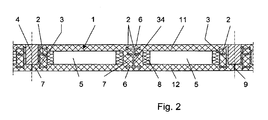
- FIG. 1 consists of the hollow plate element 1 of two spaced apart and mutually parallel plates 11, 12, wherein in FIG. 1 the top view on the upper plate 11 is shown. It can be seen that in the central region of the hollow plate element 1, two mutually parallel and mutually spaced clamping cables 2 are guided, in the central region of a likewise parallel guided web plate 3 is guided.
- FIG. 2 shows that with the help of a filling body 4, the connection to the adjacent hollow plate element 1 is achieved.
- the hollow plate member 1 has in the space between the upper and lower plates 11, 12 cavities 5, in which, for example, an insulation 8 is laid. In this cavity 5 and common installation cables, heating and cooling pipes and the like are laid. Likewise, it is provided to lay in the cross section of the lower plate 12 and heating or cooling lines.
- a web plate 3 is laid, which consists essentially of a double-T cross-section.
- This web plate 3 has a vertical leg 34, which extends over a first preferred embodiment over the entire length of the hollow plate element 1.
- this web plate 3 is only partially available.
- a number of head bolts 6 are fixed, each having a head 29 of enlarged cross-section at their outer free ends.
- the head bolts 6 are preferably made of a metal material, as well as the vertical leg 34 of the web plate. 3
- the head bolts 6 are then in this case preferably secured with a weld on the vertical leg 34 of the web plate 3.
- Purpose of this head bolt 6 is to provide a positive connection between the upper plate 11 and the lower plate 12 via the vertical leg 34 of the web plate 3, which is laid in the illustrated embodiment in the region of a concrete web 7.
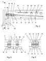
- tensioning cable 2 are each received at the ends of the hollow plate elements 1 in anchor bodies 10.
- Each anchor body 10 consists of the anchor plate 19, through which the cable outline 21, consisting of individual strands 25 is passed. These strands 25 are guided beyond the anchor plate 19 by an anchor bushing 16, deflected there in an arc and engage through a fixing plate 17 and are anchored in a cone receptacle 18. In this way, there is an immovable fixing of the strands 25 of the tensioning cable 2 in the anchor bushing sixteenth
- the adjustment of the bias voltage to the tensioning cable 2 takes place when the two plates are connected and cured according to the specified method. It is then handled with a corresponding pulling tool on the backward strands 25 and the strands are high Tensile force stretched along its longitudinal direction, then turned over and anchored in the cone seat 18 of the anchor plate 16.
- FIGS. 3 and 4 show that the hollow plate member 1 rests at its ends in each case by a construction designed as a double support 13 construction.
- the concrete web 7 is attached in order to enclose the web plate 3 with the anchor bodies 10 arranged thereon on the front, the cable outline 21 of the anchor body 10 is still surrounded by a helical reinforcement 20 in order to absorb splitting tensile forces.
- FIG. 4 Incidentally, it can be seen that the upper edge 23 of the web plate 3 does not extend to the outer edge of the upper plate 11, and also the lower edge 22 of the web plate does not extend to the bottom of the lower plate 12.
- This space is covered with concrete and in the area of the upper and lower plates are according to FIG. 7 Longitudinal and transverse reinforcements 26, 27 arranged.
- FIG. 7 also shows that in the lower plate heating cables 28 are arranged, which can be traversed by a heating or a cooling medium.
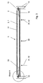
- FIG. 3 shows the basic principle of the invention, from which it can be deduced that essentially the tensioning cable assumes a trapezoidal shape 33 when it is introduced into the lower plate, wherein deflecting saddles 32 are preferably provided at the deflection points 31 in the region of the lower plate, which guides the cable guide of the tensioning cable 2 take there and thus provide the desired trapezoidal shape 33.
- the bias voltage is - as stated in the general description part - adjusted so that there is a zero deflection of the unloaded hollow plate elements 1.
- the arranged in the space between the upper and lower plate web plates 3 then need only record the traffic-related load and deflection of the hollow plate elements 1.
Landscapes
- Engineering & Computer Science (AREA)
- Architecture (AREA)
- Civil Engineering (AREA)
- Structural Engineering (AREA)
- Physics & Mathematics (AREA)
- Electromagnetism (AREA)
- Bridges Or Land Bridges (AREA)
- Diaphragms For Electromechanical Transducers (AREA)
- Audible-Bandwidth Dynamoelectric Transducers Other Than Pickups (AREA)
- Panels For Use In Building Construction (AREA)
Description
- Gegenstand der Erfindung ist ein Verfahren zur Herstellung eines Hohlplattenelementes mit großer Spannweite und niedriger Höhe sowie ein mit dem Verfahren hergestelltes Hohlplattenelement.
- Ein eingangs genanntes Hohlplattenelement ist mit dem Gegenstand der
DE 103 50 082 A1 bekannt geworden. Bei der dort gezeigten Ausführungsform handelt es sich um eine vorgespannte Flachdecke mit Hohldeckenplatten. Im Zwischenraum zwischen einer relativ dünnen oberen und unteren Platte waren hierbei Gurtstreifen aus Beton ausgegossen, in deren inneren Bereich eine Anzahl von Spannkabeln verlegt waren. Die Spannkabel waren wellenförmig über die Längsachse der Gurtstreifen verlegt und dergestalt in den Beton der Gurtstreifen eingebaut. - Durch die Anlegung einer Vorspannung an den jeweiligen Endseiten dieser Spannkabel ergab sich der Effekt, dass die auf die Spannkabel in Längsrichtung einwirkenden Spannkräfte umgelenkt wurden, um so die untere Platte in Richtung auf die obere Platte vorzuspannen. Damit ergab sich der Vorteil, dass bei einem relativ dünnen und schlanken Aufbau derartiger Hohldeckenplatten eine hohe Tragfähigkeit erzielt werden konnte.
- Nachteil der genannten Anordnung war allerdings, dass das Ausgießen von Gurtstreifen mit Beton einen relativ hohen Aufwand verursachte. Weiterer Nachteil war, dass die in Beton verlegten Spannkabel schwierig einzubauen waren, weil entsprechende Spannkabelhalter erforderlich waren und deren Verlegezustand später nicht mehr überprüft werden konnte. Es konnten mit dieser Konstruktion - wegen des Gewichts der Gurtstreifen - keine hohen Spannweiten erzielt werden. So war es nicht möglich, Spannweiten über 10 m zu erzielen, weil die Kräfte im Gurtstreifen dann das zulässige Maß überschritten.
- Verfahrensmäßig bestand bei der bekannten Druckschrift
DE 103 50 082 A1 der Nachteil, dass der Gurtstreifen mit den dort eingelegten und wellenförmig geführten Spannkabeln am Ort der Baustelle angefertigt werden musste, was mit einem hohen Herstellungsaufwand an der Baustelle verbunden war. - Die
EP 1350898 A1 offenbart ein Verfahren zur Herstellung eines Hohlplattenelementes mit sämtlichen Merkmalen des Oberbegriffes des Verfahrensanspruches 1. - Die
EP 1790789 A1 offenbart ein Verfahren zur Herstellung eines Hohlplattenelementes wobei zunächst ein Verbinden der Stegkonstruktion mit einer ersten Platte und danach ein Verbinden der oberen mit der unteren Platte erfolgt. - Der Erfindung liegt deshalb die Aufgabe zugrunde, ein Hohlplattenelement nach dem Gegenstand dem Stand der Technik so weiterzubilden, dass bei einer verbesserten Verarbeitbarkeit eine größere Spannweite bei gleichem oder sogar niedrigerem Flächengewicht mit hoher Tragfähigkeit erzielt werden kann. Weitere Aufgabe ist es, eine Verbesserung der Abstandshaltung zwischen oberer und unterer Betonplatte, sowie eine Vorspannung in der Stegkonstruktion des Hohlplattenelementes zu erzielen.
- Zur Lösung der gestellten Aufgabe ist die Erfindung durch ein Verfahren nach dem Gegenstand des Anspruches 1 gekennzeichnet.
- Wesentliches Merkmal der Erfindung ist, dass ein Hohlplattenelement nach der Erfindung sich dadurch auszeichnet, dass im Zwischenraum zwischen einer oberen und einer unteren Platte mehrere einen gegenseitigen Abstand voneinander einnehmende und zueinander parallel ausgebildete Stegbleche angeordnet sind, zu deren Längsrichtung parallel die Spannkabel verlegt sind, wobei jedes Spannkabel mit seinem einen Ende über einen Ankerkörper mit dem jeweiligen Stegblech verbunden ist, während das gegenüberliegende Ende des Spannkabels über einen anderen Ankerkörper mit dem dort liegenden Ende des Stegbleches verbunden ist.
- Mit der gegebenen technischen Lehre ergibt sich der wesentliches Vorteil, dass nun die am Ort der Baustelle vorher anzufertigenden Gurtstreifen aus Beton vollständig entfallen können und stattdessen bereits schon im Fertigbetonwerk hergestellte Stegbleche in den Zwischenraum zwischen der oberen und unteren Platte eingegossen werden und dass parallel zu diesen Stegblechen nun die erfindungsgemäßen Spannkabel gespannt werden.
- Damit ergibt sich der Vorteil, dass ein wesentlich geringeres Flächengewicht erzielt wird, denn die relativ schweren Gurtstreifen aus Beton entfallen und werden durch leichtbauende Stegbleche ersetzt.
- Die Erfindung ist nicht darauf angewiesen, dass sich die Stegbleche über die gesamte Länge der Hohlplattenelemente erstrecken. Dies ist zwar eine bevorzugte Ausführungsform der Erfindung. In einer anderen Ausführungsform der Erfindung ist es jedoch vorgesehen, dass die Stegbleche nur stückweise vorhanden sind und insbesondere nur bei den jeweiligen Stirnseiten der Hohlplattenelemente angeordnet sind und dann lediglich nur noch maximal zweimal im Bereich der Umlenkpunkte, wo die Spannkraft des jeweiligen Spannkabels in den Querschnitt der unteren Platte eingeleitet wird.
- Die im mittleren Bereich angeordneten Stegbleche dienen dann als Umlenksättel für die Einleitung des im bogen- oder bauchförmig verlegten Spannkabels in den Querschnitt der unteren Platte.
- Mit den erfindungsgemäßen Maßnahmen wird erstmals ein wesentlich verbessertes Hohlplattenelement erzielt, denn mit einer derartigen, leichten Konstruktion ist es erstmals möglich, Spannweiten von über 16 m zu erzielen, wobei ein Hohlplattenelement eine Länge von 16 m und eine Breite von 3,50 m aufweist.
- Jede Platte dieses Sandwichaufbaues (obere und untere Platte) hat hierbei eine bevorzugte Dicke von z. B. 10 cm.
- Der Zwischenraum beträgt dann bei dieser Ausführung etwa 20 cm.
- Derartige Spannweiten von Hohlelementen waren bisher fabrikationstechnisch noch nicht herstellbar. Es ist nun erstmals möglich, diese Hohlplattenelemente im Fertigbetonwerk herzustellen.
- Die Sandwichplatten, bestehend aus zwei parallelen dünnen Betonplatten und deren punktuelle Verbindung über Stahlelemente (Stegbleche) werden industriell hergestellt. Zuerst wird eine Platte mitsamt den Stahlelementen hergestellt. Dabei wird bereits das Spannkabel entlang des Stegbleches fixiert und mit den Ankerkörpern an der Ankerplatte befestigt. Nachdem die erste Platte bereits ausgehärtet ist, wird diese in den Beton der zweiten Platte eingetaucht. Nach dem Erhärten dieser Schale ist der Sandwichquerschnitt vollständig hergestellt. Nun kann die Spannkraft auf die jeweiligen Spannkabel aufgebracht werden und am Bauteilende verankert werden.
- Der Aufbau des erfindungsgemäßen Hohlplattenelementes ist wie folgt:
- Einzelne Stegbleche verbinden die obere und untere Platte der Sandwichkonstruktion, um den Schub zu übertragen. Entlang der Stegbleche wird eine Vorspannung ohne Verbund (mit Monolitzenspanngliedern) angeordnet. Die Stegbleche bieten die ideale Voraussetzung für die Anbringung von möglichen Umlenksatteln und für die Verankerungselemente.
- Auf den Verankerungsplatten wird der Ankerkörper für die Vorspannung aufgesetzt. Die Monolitzenspanglieder werden entlang des Betonsteges parallel geführt. Die Vorspannung erfolgt, nachdem die beiden Platten miteinander verbunden und ausgehärtet sind.
- Über die Verankerungsplatten als Kopfelemente an den Stegblechen wird die Spannkraft in den Betonsteg und dann über die Stegbleche in die Betonplatten eingeleitet.
- Mit dem Gegenstand der Erfindung ergibt sich der Vorteil, dass nun die Spannkabel nicht mehr wellenförmig in einem aus Beton gefertigten Gurtstreifen verlegt werden müssen, sondern sie sind als einfache Monolitzenkabel ausgebildet und gehen mit ihrer bauchförmigen Durchbiegung in den Querschnitt der unteren Platte hinein und sind dort verankert.
- Um eine definierte Übertragung der Spannkräfte auf die untere Platte zu erreichen, ist es vorgesehen, dass an den Eintrittsstellen des Spannkabels in den Querschnitt der unteren Platte sogenannte Umlenksättel vorhanden sind, um dort die Spannkräfte des Kabels in den Querschnitt der unteren Platte einzuleiten.
- Damit wird in der Seitenansicht des Spannkabels nicht mehr ein durchhängender Bauch des Spannkabels erzeugt, sondern eine trapezförmige Führung des Spannkabels zwischen den einander gegenüberliegenden Ankerkörpern.
- Damit wird wesentliches Gewicht erspart, denn im einfachsten Fall müssen nur noch an den Umlenksätteln entsprechende Stegbleche vorgesehen werden, welche eine Verbindung zu der oberen Platte erbringen.
- Derartige Stegbleche müssen nicht notwendigerweise aus einem Metallelement bestehen. Sie können auch als Betonelement oder als Kunststoffelement oder aus Glasfaser-Beton bestehen. Ebenso können beliebige Verbundkörper aus Beton und Metall verwendet werden.
- Bei der nur stückweise Verwendung von Stegblechen wird der weitere Vorteil erzielt, dass der Zwischenraum zwischen den Sandwichplatten vollkommen von Einbauten freigehalten wird und der Zwischenraum für die Verlegung von Heizungsrohren, Installationsrohren und anderen Elementen zur Verfügung steht.
- Wird hingegen ein sich über die gesamte Länge des Hohlplattenelementes erstreckendes Stegblech verwendet, hat dieses zweckmäßigerweise an bestimmten Stellen Durchbrechungen und Ausnehmungen, um dort eine Hindurchführung von Installationsrohren und Kabeln zu ermöglichen.
- Mit den angegebenen Maßnahmen ist es nun auf einfache Weise möglich, die Durchbiegung der gesamten Platte zu beherrschen, denn in einer bevorzugten Ausgestaltung wird die Spannung an den Spannkabeln so eingestellt, dass die Umlenkspannung der Spannkabel im Eigengewicht des gesamten Hohlplattenelementes entspricht. Damit ist dieses Hohlplattenelement im Ruhezustand statisch definiert und hat keinerlei Durchbiegung und muss dann lediglich nur noch die durch Verkehrsbelastung entstehende Durchbiegung aufnehmen. Hierzu sind dann die erfindungsgemäßen Stegelemente vorgesehen.
- Wesentlich ist hierbei, dass eine Null-Durchbiegung des Hohlplattenelementes aufgrund der angelegten Spannung der Spannkabel eingestellt wird und dass dadurch ein Kriechen des Betons nach dem Aushärten vermieden wird, wenn Druck auf den Beton kommt.
- Durch die Verwendung der erfindungsgemäßen Stegbleche wird die Kraft von der oberen Platte auf die untere übertragen und beide werden somit gleichmäßig belastet und durch die Vorspannung der Spannkabel gegen Durchbiegung geschützt. Im Folgenden wird die Erfindung anhand von lediglich einen Ausführungsweg darstellenden Zeichnungen näher erläutert,
- Es zeigen:
- Figur 1:
- Draufsicht auf ein Hohlplattenelement nach der Erfindung
- Figur 2:
- Schnitt gemäß der Linie 1-1 in
Figur 2 - Figur 3:
- Schnitt gemäß der Linie 2-2 in
Figur 1 - Figur 4:
- eine vergrößerte Seitenansicht aus dem Schnitt nach
Figur 3 - Figur 5:
- Schnitt gemäß der Linie 1-1 in
Figur 4 - Figur 6:
- ein gleicher Schnitt in Richtung 1-1 bei einem in Plattenmitte angeordneten Stegblech
- Figur 7:
- eine vergrößerte Darstellung eines in Plattenmitte verlegten Stegbleches gemäß
Figur 2 - In
Figur 1 besteht das Hohlplattenelement 1 aus zwei im Abstand und parallel zueinander angeordneten Platten 11, 12, wobei inFigur 1 die Draufsicht auf die obere Platte 11 dargestellt ist. Es ist erkennbar, dass im Mittenbereich des Hohlplattenelementes 1 zwei zueinander parallele und im gegenseitigen Abstand zueinander angeordnete Spannkabel 2 geführt sind, in deren Mittenbereich ein gleichfalls parallel geführtes Stegblech 3 geführt ist. - An den äußeren Stirnseiten der Hohlplattenelementes 1 sind lediglich nur noch einzelne Spannkabel 2 geführt, wobei die
Figur 2 zeigt, dass mit Hilfe eines Verfüllkörpers 4 der Anschluss zu dem benachbarten Hohlplattenelement 1 erzielt wird. - Das Hohlplattenelement 1 weist in dem Zwischenraum zwischen der oberen und unteren Platte 11, 12 Hohlräume 5 auf, in denen beispielsweise eine Isolation 8 verlegt ist. In diesem Hohlraum 5 sind auch übliche Installationsleitungen, Heiz- und Kühlleitungen und dergleichen verlegt. Ebenso ist es vorgesehen, im Querschnitt der unteren Platte 12 auch Heiz- oder Kühlleitungen zu verlegen.
- Wichtig ist nun, dass im Verbindungsbereich, d. h. im Bereich von Betonstegen 7 des Hohlplattenelementes 1 ein Stegblech 3 verlegt ist, welches im Wesentlichen aus einem Doppel-T-Querschnitt besteht. Dieses Stegblech 3 hat einen vertikalen Schenkel 34, der sich nach einer ersten bevorzugten Ausgestaltung über die gesamte Länge des Hohlplattenelementes 1 erstreckt.
- In einer anderen Ausgestaltung ist dieses Stegblech 3 nur abschnittsweise vorhanden.
- An den vertikalen Schenkeln 34 des Stegbleches 3 sind im gegenseitigen Abstand in Längsrichtung des Hohlplattenelementes 1 gesehen eine Anzahl von Kopfbolzen 6 befestigt, die an ihren äußeren freien Enden jeweils einen Kopf 29 vergrößerten Querschnitts aufweisen.
- Die Kopfbolzen 6 sind bevorzugt aus einem Metallmaterial, ebenso wie der vertikale Schenkel 34 des Stegbleches 3.
- Die Kopfbolzen 6 sind dann hierbei bevorzugt mit einer Verschweißung an dem vertikalen Schenkel 34 des Stegbleches 3 befestigt.
- Zweck dieser Kopfbolzen 6 ist, eine formschlüssige Verbindung zwischen der oberen Platte 11 und der unteren Platte 12 über den vertikalen Schenkel 34 des Stegbleches 3 zu erbringen, der im gezeigten Ausführungsbeispiel im Bereich eines Betonsteges 7 verlegt ist.
- Zwischen den aneinander stoßenden Hohlplattenelementen 1 ergibt sich gemäß
Figur 2 unterhalb des Verfüllkörpers 4 eine Fuge 9, welche die Trennfuge zwischen den Hohlplattenelementen 1 darstellt. - Wie aus
Figur 1 zu entnehmen, sind die Spannkabel 2 jeweils an den Enden der Hohlplattenelemente 1 in Ankerkörpern 10 aufgenommen. - Gemäß
Figur 4 besteht jeder Ankerkörper 10 aus der Ankerplatte 19, durch welche der Kabelumriss 21, bestehend aus einzelnen Litzen 25 hindurchgeführt ist. Diese Litzen 25 sind jenseits der Ankerplatte 19 durch eine Ankerbuchse 16 geführt, dort im Bogen umgelenkt und greifen durch eine Fixierplatte 17 hindurch und sind in einer Konusaufnahme 18 verankert. Auf diese Weise kommt es zu einer unverrückbaren Festlegung der Litzen 25 der Spannkabel 2 in der Ankerbuchse 16. - Die Einstellung der Vorspannung an dem Spannkabel 2 erfolgt dann, wenn die beiden Platten gemäß dem angegebenen Verfahren miteinander verbunden und ausgehärtet sind. Es wird dann mit einem entsprechenden Zugwerkzeug an den nach hinten gerichteten Litzen 25 angefasst und die Litzen werden mit hoher Zugkraft entlang ihrer Längsrichtung gespannt, dann umgeschlagen und in der Konusaufnahme 18 der Ankerplatte 16 verankert.
- Die
Figuren 3 und4 zeigen, dass das Hohlplattenelement 1 an seinen Enden jeweils von einer als doppelte Stütze 13 ausgebildeten Konstruktion aufliegt. - Sofern ein sich über die gesamte Länge erstreckendes Stegblech 3 verwendet wird, ist es gemäß
Figur 4 vorgesehen, dass dort Öffnungen 14, 15 vorgesehen sind, um entsprechende Isolationskabel und Leitungen hindurchzuführen. - Sofern nach dem einen Ausführungsbeispiel der Betonsteg 7 angebracht ist, um das Stegblech 3 mit den dort stirnseitig angeordneten Ankerkörpern 10 zu umschließen, wird der Kabelumriss 21 des Ankerkörpers 10 noch mit einer Wendelbewehrung 20 umgeben, um Spaltzugkräfte aufzunehmen.
- In
Figur 4 ist im Übrigen zu entnehmen, dass die Oberkante 23 des Stegbleches 3 sich nicht bis zum äußeren Rand der oberen Platte 11 erstreckt, und ebenso erstreckt sich die Unterkante 22 des Stegbleches nicht bis auf die Unterseite der unteren Platte 12. Dieser Zwischenraum ist mit Beton überdeckt und im Bereich der oberen und unteren Platten sind gemäßFigur 7 Längs- und Querbewehrungen 26, 27 angeordnet. - Die
Figur 7 zeigt auch, dass im Bereich der unteren Platte Heizleitungen 28 angeordnet sind, die von einem Heiz- oder einem Kühlmedium durchflossen werden können. - Die
Figur 3 zeigt das Grundprinzip der Erfindung, aus dem entnehmbar ist, dass im Wesentlichen das Spannkabel bei seiner Einleitung in die untere Platte eine Trapezform 33 einnimmt, wobei bevorzugt an den Umlenkpunkten 31 im Bereich der unteren Platte Umlenksättel 32 vorgesehen sind, welche die Kabelführung des Spannkabels 2 dort aufnehmen und somit die gewünschte Trapezform 33 erbringen. - Bei Einwirkung einer Spannkraft auf das Spannkabel 2 nach
Figur 3 wird somit das gesamte Hohlplattenelement 1 in Pfeilrichtung 30 angehoben und vorgespannt. - Die Vorspannung wird - wie im allgemeinen Beschreibungsteil angegeben - so eingestellt, dass es eine Null-Durchbiegung der unbelasteten Hohlplattenelemente 1 ergibt. Die im Zwischenraum zwischen der oberen und unteren Platte angeordneten Stegbleche 3 müssen dann nur noch die verkehrsbedingte Belastung und Durchbiegung der Hohlplattenelemente 1 aufnehmen.
-
- 1
- Hohlplattenelement
- 2
- Spannkabel
- 3
- Stegblech
- 4
- Verfüllkörper
- 5
- Hohlraum
- 6
- Kopfbolzen
- 7
- Betonstege
- 8
- Isolation
- 9
- Fuge
- 10
- Ankerkörper
- 11
- Obere Platte
- 12
- Untere Platte
- 13
- Stütze
- 14
- Öffnung (Stegblech 3)
- 15
- Öffnung (Stegblech 3)
- 16
- Ankerbuchse
- 17
- Fixierplatte
- 18
- Konusaufnahme
- 19
- Ankerplatte
- 20
- Wendelbewehrung
- 21
- Kabelumriss
- 22
- Unterkante Stegblech
- 23
- Oberkante Stegblech
- 24
- Zwischenraum
- 25
- Litze
- 26
- Querbewehrung
- 27
- Längsbewehrung
- 28
- Heizleitung
- 29
- Kopf (Kopfbolzen 6)
- 30
- Pfeilrichtung
- 31
- Umlenkpunkt
- 32
- Umlenksattel
- 33
- Trapezform
- 34
- vertikaler Schenkel
Claims (7)
- Verfahren zur Herstellung eines Hohlplattenelementes (1), welches zwischen einer oberen und unteren angeordneten Betonplatte (11, 12) einen Hohlraum (5) ausbildet, welche in ihrem inneren Bereich mit einer Anzahl von über die Längsachse von Betonstegen (7) verlegte Spannkabel (2) ausgebildet sind, wobei im Hohlraum (5) zwischen der oberen und unteren Betonplatte (11, 12) des Hohlplattenelementes (1) mehrere, einen gegenseitigen Abstand voneinander einnehmende und zueinander parallel ausgebildete Elemente (3) angeordnet sind, zu deren Längsrichtung parallel die Spannkabel (2) verlegt sind, dadurch gekennzeichnet, dass die Elemente (3) Stegbleche (3) sind, wobei jedes Spannkabel (2) mit seinem einen Ende über einen Ankerkörper (10) mit dem jeweiligen Stegblech (3) verbunden ist, während das gegenüberliegende Ende des Spannkabels (2) über einen anderen Ankerkörper (10) mit dem dort liegenden Ende des Stegbleches (3) verbunden ist, wobei die Herstellung eines Hohlplattenelementes (1) folgende Schritte aufweist:- Anbringen von Verankerungselementen (6, 16-20) und Umlenksätteln (32) auf dem Stegblech (3);- Verbinden der Stegbleche (3) mit der oberen oder unteren Betonplatte (11, 12);- Einbringen von Spannkabeln (2) parallel zum Stegblech (3);- Verbinden der oberen Betonplatte (11) mit der unteren Betonplatte (12);- Vorspannen der Spannkabel (2) nach Verbindung und Aushärtung der beiden Betonplatten (11, 12) durch Einleiten einer Spannkraft in den Betonsteg (7), über die Stegbleche (3) in die Betonplatten (11, 12).
- Verfahren zur Herstellung eines Hohlplattenelementes (1) nach Anspruch 1, dadurch gekennzeichnet, dass das Spannkabel (2) mit einer bauchförmigen Durchbiegung an der unteren Betonplatte (12) mittels der Umlenksättel (32) verankert wird und eine trapezförmige Führung des Spannkabels (2) ausbildet.
- Hohlplattenelement (1), hergestellt gemäß dem Verfahren nach einem der vorher gehenden Ansprüche 1 oder 2, dadurch gekennzeichnet, dass an den äußeren Stirnseiten des Hohlplattenelementes (1) lediglich einzelne Spannkabel (2) geführt sind und das Hohlplattenelement (1) mittels einem Verfüllkörper (4) an ein benachbartes Hohlplattenelement (1) angeschlossen ist, wobei unterhalb des Verfüllkörpers (4) eine Fuge (9) als Trennfuge zwischen den benachbarten Hohlplattenelementen (1) ausgebildet ist.
- Hohlplattenelement (1) nach Anspruch 3, dadurch gekennzeichnet, dass das Stegblech (3) einen Doppel-T-Querschnitt mit einem vertikalen Schenkel (34) aufweist, wobei sich das Stegblech (3) über die gesamte Länge des Hohlplattenelementes (1) erstreckt.
- Hohlplattenelement (1) nach Anspruch 4, dadurch gekennzeichnet, dass der vertikale Schenkel (34) des Stegbleches (3) in Längsrichtung gegenseitig beabstandete Kopfbolzen (6) aufweist, welche an Ihren freien Enden jeweils einen Kopf (29) vergrößerten Querschnitts aufweisen und aus einem Metallmaterial gebildet sind, wobei die Kopfbolzen (6) mittels einer Schweißverbindung an dem vertikalen Schenkel (34) befestigt sind.
- Hohlplattenelement (1) nach Anspruch 5, dadurch gekennzeichnet, dass die Kopfbolzen (6) eine formschlüssige Verbindung zwischen der oberen Betonplatte (11) und der unteren Betonplatte (12) des Hohlplattenelementes (1) über den vertikalen Schenkel (34) des Stegbleches (3) ausbilden, welcher im Bereich des Betonsteges (7) angeordnet ist.
- Hohlplattenelement (1) nach einem der vorhergehenden Ansprüche 1 bis 6, dadurch gekennzeichnet, dass der Ankerkörper (10) eine Ankerplatte (19) aufweist, durch welche der einzelne Litzen (25) aufweisende Kabelumriss (21) geführt ist, wobei die Litzen (25) jenseits der Ankerplatte (19) durch eine Ankerbuchse (16) geführt sind, im Bogen umgelenkt sind, durch eine Fixierplatte (17) hindurch greifen und in einer Konusaufnahme (18) verankert sind und damit eine unverrückbare Festlegung der Spannkabel (2) in der Ankerbuchse (16) ausbilden.
Applications Claiming Priority (1)
| Application Number | Priority Date | Filing Date | Title |
|---|---|---|---|
| DE102008011689A DE102008011689A1 (de) | 2008-02-28 | 2008-02-28 | Hohlplattenelement mit großer Spannweite und niedriger Höhe |
Publications (2)
| Publication Number | Publication Date |
|---|---|
| EP2096220A1 EP2096220A1 (de) | 2009-09-02 |
| EP2096220B1 true EP2096220B1 (de) | 2011-04-13 |
Family
ID=40749821
Family Applications (1)
| Application Number | Title | Priority Date | Filing Date |
|---|---|---|---|
| EP09002839A Active EP2096220B1 (de) | 2008-02-28 | 2009-02-27 | Vorgespanntes Hohlplattenelement |
Country Status (3)
| Country | Link |
|---|---|
| EP (1) | EP2096220B1 (de) |
| AT (1) | ATE505599T1 (de) |
| DE (2) | DE102008011689A1 (de) |
Families Citing this family (1)
| Publication number | Priority date | Publication date | Assignee | Title |
|---|---|---|---|---|
| CN115338973B (zh) * | 2022-09-08 | 2023-07-14 | 山东大学 | 一种钢肋混凝土上翼缘板的正向制作设备及制作方法 |
Family Cites Families (8)
| Publication number | Priority date | Publication date | Assignee | Title |
|---|---|---|---|---|
| GB650634A (en) * | 1948-06-11 | 1951-02-28 | Ariosto Semeraro | Improved method of erecting houses or other structures from prefabricated elements |
| FR2610656B1 (fr) * | 1987-02-11 | 1991-06-21 | Citra | Dispositif pour guider les cables de precontrainte d'un ouvrage de genie civil |
| ES2161199B1 (es) | 2000-05-16 | 2002-07-01 | Sanchez Jaime Enrique Jimenez | Procedimiento de fabricacion de placa alveolar ligera materializada en obra, placa asi obtenida y su aplicacion en viviendas. |
| KR100423757B1 (ko) * | 2001-05-04 | 2004-03-22 | 원대연 | 프리스트레스트 합성 트러스 보 및 그의 제조 방법 |
| AU2003262578A1 (en) * | 2002-08-28 | 2004-03-19 | Carlos Fradera Pellicer | Method of producing a light facade panel for construction, means for the production and installation of same, the light facade panel thus obtained and use thereof |
| EP1405961B1 (de) * | 2002-10-05 | 2006-01-04 | Dywidag-Systems International GmbH | Stahl-Verbund-Konstruktion für Geschossdecken |
| DE10350082B4 (de) * | 2003-10-27 | 2007-02-22 | Rudolph, Hermann, Dipl.-Ing. | Vorgespannte Flachdecke mit Hohldeckenplatten |
| EP1790789A1 (de) | 2005-11-28 | 2007-05-30 | Bartoli N.V. | Bausystem, Trägerelement, Stütze und Verfahren |
-
2008
- 2008-02-28 DE DE102008011689A patent/DE102008011689A1/de not_active Withdrawn
-
2009
- 2009-02-27 AT AT09002839T patent/ATE505599T1/de active
- 2009-02-27 DE DE502009000516T patent/DE502009000516D1/de active Active
- 2009-02-27 EP EP09002839A patent/EP2096220B1/de active Active
Also Published As
| Publication number | Publication date |
|---|---|
| ATE505599T1 (de) | 2011-04-15 |
| DE102008011689A1 (de) | 2009-12-10 |
| DE502009000516D1 (de) | 2011-05-26 |
| EP2096220A1 (de) | 2009-09-02 |
Similar Documents
| Publication | Publication Date | Title |
|---|---|---|
| EP1007809B1 (de) | Verstärkungsvorrichtung für tragstrukturen | |
| EP2912239B1 (de) | Armierungselement zur herstellung vorgespannter betonbauteile, betonbauteil und herstellverfahren | |
| DE112010000467T5 (de) | Scherverstärkungsmaterial des kragträgertyps mit doppeltenverankerungsfunktionen an oberseite und unterseite | |
| EP2646627B1 (de) | Einrichtung zum anschliessen von stahlbetonplatten an eine wand- oder deckenkonstruktion aus stahlbeton | |
| EP0755473B1 (de) | Dübelleiste für schubbewehrungen | |
| EP1040238B1 (de) | Schubbewehrung für flachdecken und dübelleiste hierfür | |
| DE3001309A1 (de) | Tragsystem fuer baukonstruktionen | |
| EP2239119B1 (de) | Mobiles Spannbett für Beton-Fertigteilelemente mit vorgespannter Bewehrung | |
| DE102009013241B4 (de) | Aus einem einstückigen Stahlbauprofil bestehender Träger | |
| EP1795667A2 (de) | Bewehrungselement für Tragwerke aus Stahlbeton, Spannbeton oder dergleichen | |
| DE202023105561U1 (de) | Energieaufnehmendes Segment und segmentartige kombinierte knickverhindernde energieaufnehmende Stützstruktur | |
| EP2189586B1 (de) | Plattenelement mit Verstärkung | |
| EP2130984A2 (de) | Lastverteilkörper mit Profilträgersystem | |
| DE102019133999A1 (de) | Anordnung zum Verbinden eines Bauwerkteils mit einem dem Bauwerkteil vorgelagerten Außenteil | |
| EP2096220B1 (de) | Vorgespanntes Hohlplattenelement | |
| DE19831984C2 (de) | Bauteil mit externen Spanngliedern | |
| EP2459812A1 (de) | Stahlbetonbauteil mit bewehrung aus z-förmigen blechteilen | |
| DE19530572C2 (de) | Gebäude-Tragkonstruktion | |
| EP0796961B1 (de) | Porenbeton-Bauteil mit einer Bewehrungsanordnung | |
| EP0947640A2 (de) | Bewehrung mit hochfestem Verbund | |
| DE102016121713A1 (de) | Segmentbrücke | |
| DE102020114611B3 (de) | Schalungsanordnung | |
| EP2080841A2 (de) | Kragplattenanschlusselement | |
| EP2241699A2 (de) | Ankerhülse für die Verankerung von vorgespannten Bewehrungselementen | |
| EP1008691B1 (de) | Betonbrücke mit externer Vorspannung |
Legal Events
| Date | Code | Title | Description |
|---|---|---|---|
| PUAI | Public reference made under article 153(3) epc to a published international application that has entered the european phase |
Free format text: ORIGINAL CODE: 0009012 |
|
| AK | Designated contracting states |
Kind code of ref document: A1 Designated state(s): AT BE BG CH CY CZ DE DK EE ES FI FR GB GR HR HU IE IS IT LI LT LU LV MC MK MT NL NO PL PT RO SE SI SK TR |
|
| AX | Request for extension of the european patent |
Extension state: AL BA RS |
|
| 17P | Request for examination filed |
Effective date: 20100122 |
|
| 17Q | First examination report despatched |
Effective date: 20100216 |
|
| AKX | Designation fees paid |
Designated state(s): AT BE BG CH CY CZ DE DK EE ES FI FR GB GR HR HU IE IS IT LI LT LU LV MC MK MT NL NO PL PT RO SE SI SK TR |
|
| GRAP | Despatch of communication of intention to grant a patent |
Free format text: ORIGINAL CODE: EPIDOSNIGR1 |
|
| GRAS | Grant fee paid |
Free format text: ORIGINAL CODE: EPIDOSNIGR3 |
|
| GRAA | (expected) grant |
Free format text: ORIGINAL CODE: 0009210 |
|
| AK | Designated contracting states |
Kind code of ref document: B1 Designated state(s): AT BE BG CH CY CZ DE DK EE ES FI FR GB GR HR HU IE IS IT LI LT LU LV MC MK MT NL NO PL PT RO SE SI SK TR |
|
| REG | Reference to a national code |
Ref country code: GB Ref legal event code: FG4D Free format text: NOT ENGLISH |
|
| REG | Reference to a national code |
Ref country code: CH Ref legal event code: EP |
|
| REG | Reference to a national code |
Ref country code: IE Ref legal event code: FG4D Free format text: LANGUAGE OF EP DOCUMENT: GERMAN |
|
| REF | Corresponds to: |
Ref document number: 502009000516 Country of ref document: DE Date of ref document: 20110526 Kind code of ref document: P |
|
| REG | Reference to a national code |
Ref country code: DE Ref legal event code: R096 Ref document number: 502009000516 Country of ref document: DE Effective date: 20110526 |
|
| REG | Reference to a national code |
Ref country code: CH Ref legal event code: NV Representative=s name: LUCHS & PARTNER AG PATENTANWAELTE |
|
| REG | Reference to a national code |
Ref country code: NL Ref legal event code: T3 |
|
| LTIE | Lt: invalidation of european patent or patent extension |
Effective date: 20110413 |
|
| PG25 | Lapsed in a contracting state [announced via postgrant information from national office to epo] |
Ref country code: PT Free format text: LAPSE BECAUSE OF FAILURE TO SUBMIT A TRANSLATION OF THE DESCRIPTION OR TO PAY THE FEE WITHIN THE PRESCRIBED TIME-LIMIT Effective date: 20110816 Ref country code: SE Free format text: LAPSE BECAUSE OF FAILURE TO SUBMIT A TRANSLATION OF THE DESCRIPTION OR TO PAY THE FEE WITHIN THE PRESCRIBED TIME-LIMIT Effective date: 20110413 Ref country code: LT Free format text: LAPSE BECAUSE OF FAILURE TO SUBMIT A TRANSLATION OF THE DESCRIPTION OR TO PAY THE FEE WITHIN THE PRESCRIBED TIME-LIMIT Effective date: 20110413 Ref country code: NO Free format text: LAPSE BECAUSE OF FAILURE TO SUBMIT A TRANSLATION OF THE DESCRIPTION OR TO PAY THE FEE WITHIN THE PRESCRIBED TIME-LIMIT Effective date: 20110713 Ref country code: HR Free format text: LAPSE BECAUSE OF FAILURE TO SUBMIT A TRANSLATION OF THE DESCRIPTION OR TO PAY THE FEE WITHIN THE PRESCRIBED TIME-LIMIT Effective date: 20110413 |
|
| REG | Reference to a national code |
Ref country code: IE Ref legal event code: FD4D |
|
| PG25 | Lapsed in a contracting state [announced via postgrant information from national office to epo] |
Ref country code: ES Free format text: LAPSE BECAUSE OF FAILURE TO SUBMIT A TRANSLATION OF THE DESCRIPTION OR TO PAY THE FEE WITHIN THE PRESCRIBED TIME-LIMIT Effective date: 20110724 Ref country code: LV Free format text: LAPSE BECAUSE OF FAILURE TO SUBMIT A TRANSLATION OF THE DESCRIPTION OR TO PAY THE FEE WITHIN THE PRESCRIBED TIME-LIMIT Effective date: 20110413 Ref country code: SI Free format text: LAPSE BECAUSE OF FAILURE TO SUBMIT A TRANSLATION OF THE DESCRIPTION OR TO PAY THE FEE WITHIN THE PRESCRIBED TIME-LIMIT Effective date: 20110413 Ref country code: GR Free format text: LAPSE BECAUSE OF FAILURE TO SUBMIT A TRANSLATION OF THE DESCRIPTION OR TO PAY THE FEE WITHIN THE PRESCRIBED TIME-LIMIT Effective date: 20110714 Ref country code: CY Free format text: LAPSE BECAUSE OF FAILURE TO SUBMIT A TRANSLATION OF THE DESCRIPTION OR TO PAY THE FEE WITHIN THE PRESCRIBED TIME-LIMIT Effective date: 20110413 Ref country code: IS Free format text: LAPSE BECAUSE OF FAILURE TO SUBMIT A TRANSLATION OF THE DESCRIPTION OR TO PAY THE FEE WITHIN THE PRESCRIBED TIME-LIMIT Effective date: 20110813 Ref country code: FI Free format text: LAPSE BECAUSE OF FAILURE TO SUBMIT A TRANSLATION OF THE DESCRIPTION OR TO PAY THE FEE WITHIN THE PRESCRIBED TIME-LIMIT Effective date: 20110413 |
|
| PLBI | Opposition filed |
Free format text: ORIGINAL CODE: 0009260 |
|
| PG25 | Lapsed in a contracting state [announced via postgrant information from national office to epo] |
Ref country code: IE Free format text: LAPSE BECAUSE OF FAILURE TO SUBMIT A TRANSLATION OF THE DESCRIPTION OR TO PAY THE FEE WITHIN THE PRESCRIBED TIME-LIMIT Effective date: 20110413 Ref country code: CZ Free format text: LAPSE BECAUSE OF FAILURE TO SUBMIT A TRANSLATION OF THE DESCRIPTION OR TO PAY THE FEE WITHIN THE PRESCRIBED TIME-LIMIT Effective date: 20110413 Ref country code: EE Free format text: LAPSE BECAUSE OF FAILURE TO SUBMIT A TRANSLATION OF THE DESCRIPTION OR TO PAY THE FEE WITHIN THE PRESCRIBED TIME-LIMIT Effective date: 20110413 |
|
| 26 | Opposition filed |
Opponent name: HERMANN RUDOLPH BAUSTOFFWERK GMBH Effective date: 20120113 |
|
| PG25 | Lapsed in a contracting state [announced via postgrant information from national office to epo] |
Ref country code: PL Free format text: LAPSE BECAUSE OF FAILURE TO SUBMIT A TRANSLATION OF THE DESCRIPTION OR TO PAY THE FEE WITHIN THE PRESCRIBED TIME-LIMIT Effective date: 20110413 Ref country code: SK Free format text: LAPSE BECAUSE OF FAILURE TO SUBMIT A TRANSLATION OF THE DESCRIPTION OR TO PAY THE FEE WITHIN THE PRESCRIBED TIME-LIMIT Effective date: 20110413 |
|
| PLAX | Notice of opposition and request to file observation + time limit sent |
Free format text: ORIGINAL CODE: EPIDOSNOBS2 |
|
| REG | Reference to a national code |
Ref country code: DE Ref legal event code: R026 Ref document number: 502009000516 Country of ref document: DE Effective date: 20120113 |
|
| PG25 | Lapsed in a contracting state [announced via postgrant information from national office to epo] |
Ref country code: IT Free format text: LAPSE BECAUSE OF FAILURE TO SUBMIT A TRANSLATION OF THE DESCRIPTION OR TO PAY THE FEE WITHIN THE PRESCRIBED TIME-LIMIT Effective date: 20110413 |
|
| PLBB | Reply of patent proprietor to notice(s) of opposition received |
Free format text: ORIGINAL CODE: EPIDOSNOBS3 |
|
| PG25 | Lapsed in a contracting state [announced via postgrant information from national office to epo] |
Ref country code: MC Free format text: LAPSE BECAUSE OF NON-PAYMENT OF DUE FEES Effective date: 20120229 |
|
| REG | Reference to a national code |
Ref country code: FR Ref legal event code: ST Effective date: 20121031 |
|
| PG25 | Lapsed in a contracting state [announced via postgrant information from national office to epo] |
Ref country code: FR Free format text: LAPSE BECAUSE OF NON-PAYMENT OF DUE FEES Effective date: 20120229 |
|
| PG25 | Lapsed in a contracting state [announced via postgrant information from national office to epo] |
Ref country code: MK Free format text: LAPSE BECAUSE OF FAILURE TO SUBMIT A TRANSLATION OF THE DESCRIPTION OR TO PAY THE FEE WITHIN THE PRESCRIBED TIME-LIMIT Effective date: 20110413 |
|
| PG25 | Lapsed in a contracting state [announced via postgrant information from national office to epo] |
Ref country code: BG Free format text: LAPSE BECAUSE OF FAILURE TO SUBMIT A TRANSLATION OF THE DESCRIPTION OR TO PAY THE FEE WITHIN THE PRESCRIBED TIME-LIMIT Effective date: 20110713 |
|
| PG25 | Lapsed in a contracting state [announced via postgrant information from national office to epo] |
Ref country code: MT Free format text: LAPSE BECAUSE OF FAILURE TO SUBMIT A TRANSLATION OF THE DESCRIPTION OR TO PAY THE FEE WITHIN THE PRESCRIBED TIME-LIMIT Effective date: 20110413 |
|
| GBPC | Gb: european patent ceased through non-payment of renewal fee |
Effective date: 20130227 |
|
| PG25 | Lapsed in a contracting state [announced via postgrant information from national office to epo] |
Ref country code: GB Free format text: LAPSE BECAUSE OF NON-PAYMENT OF DUE FEES Effective date: 20130227 |
|
| PG25 | Lapsed in a contracting state [announced via postgrant information from national office to epo] |
Ref country code: TR Free format text: LAPSE BECAUSE OF FAILURE TO SUBMIT A TRANSLATION OF THE DESCRIPTION OR TO PAY THE FEE WITHIN THE PRESCRIBED TIME-LIMIT Effective date: 20110413 |
|
| PG25 | Lapsed in a contracting state [announced via postgrant information from national office to epo] |
Ref country code: HU Free format text: LAPSE BECAUSE OF FAILURE TO SUBMIT A TRANSLATION OF THE DESCRIPTION OR TO PAY THE FEE WITHIN THE PRESCRIBED TIME-LIMIT Effective date: 20090227 |
|
| PLBP | Opposition withdrawn |
Free format text: ORIGINAL CODE: 0009264 |
|
| PLBD | Termination of opposition procedure: decision despatched |
Free format text: ORIGINAL CODE: EPIDOSNOPC1 |
|
| REG | Reference to a national code |
Ref country code: DE Ref legal event code: R100 Ref document number: 502009000516 Country of ref document: DE |
|
| PLBM | Termination of opposition procedure: date of legal effect published |
Free format text: ORIGINAL CODE: 0009276 |
|
| STAA | Information on the status of an ep patent application or granted ep patent |
Free format text: STATUS: OPPOSITION PROCEDURE CLOSED |
|
| 27C | Opposition proceedings terminated |
Effective date: 20171223 |
|
| PGFP | Annual fee paid to national office [announced via postgrant information from national office to epo] |
Ref country code: BE Payment date: 20230227 Year of fee payment: 15 |
|
| PGFP | Annual fee paid to national office [announced via postgrant information from national office to epo] |
Ref country code: LU Payment date: 20240226 Year of fee payment: 16 |
|
| PGFP | Annual fee paid to national office [announced via postgrant information from national office to epo] |
Ref country code: NL Payment date: 20240220 Year of fee payment: 16 |
|
| PGFP | Annual fee paid to national office [announced via postgrant information from national office to epo] |
Ref country code: AT Payment date: 20240216 Year of fee payment: 16 |
|
| PGFP | Annual fee paid to national office [announced via postgrant information from national office to epo] |
Ref country code: DE Payment date: 20240216 Year of fee payment: 16 Ref country code: CH Payment date: 20240301 Year of fee payment: 16 |