EP2096220B1 - Elément de plaques creuses préconstraintes - Google Patents
Elément de plaques creuses préconstraintes Download PDFInfo
- Publication number
- EP2096220B1 EP2096220B1 EP09002839A EP09002839A EP2096220B1 EP 2096220 B1 EP2096220 B1 EP 2096220B1 EP 09002839 A EP09002839 A EP 09002839A EP 09002839 A EP09002839 A EP 09002839A EP 2096220 B1 EP2096220 B1 EP 2096220B1
- Authority
- EP
- European Patent Office
- Prior art keywords
- plate
- web
- hollow slab
- concrete
- hollow
- Prior art date
- Legal status (The legal status is an assumption and is not a legal conclusion. Google has not performed a legal analysis and makes no representation as to the accuracy of the status listed.)
- Active
Links
- 239000004567 concrete Substances 0.000 claims abstract description 37
- 238000000034 method Methods 0.000 claims abstract description 7
- 238000004873 anchoring Methods 0.000 claims description 11
- 238000004519 manufacturing process Methods 0.000 claims description 8
- 239000007769 metal material Substances 0.000 claims description 2
- 239000011796 hollow space material Substances 0.000 claims 2
- 238000010276 construction Methods 0.000 description 10
- 238000010438 heat treatment Methods 0.000 description 6
- 238000009434 installation Methods 0.000 description 5
- 210000002414 leg Anatomy 0.000 description 5
- 230000002787 reinforcement Effects 0.000 description 5
- 229910000831 Steel Inorganic materials 0.000 description 2
- 210000001015 abdomen Anatomy 0.000 description 2
- 239000002131 composite material Substances 0.000 description 2
- 238000001816 cooling Methods 0.000 description 2
- 238000009413 insulation Methods 0.000 description 2
- 239000002184 metal Substances 0.000 description 2
- 239000011178 precast concrete Substances 0.000 description 2
- 239000010959 steel Substances 0.000 description 2
- 239000002826 coolant Substances 0.000 description 1
- 230000001419 dependent effect Effects 0.000 description 1
- 230000000694 effects Effects 0.000 description 1
- 238000005516 engineering process Methods 0.000 description 1
- 239000011152 fibreglass Substances 0.000 description 1
- 238000002955 isolation Methods 0.000 description 1
- 239000004033 plastic Substances 0.000 description 1
- 238000007665 sagging Methods 0.000 description 1
- 239000002356 single layer Substances 0.000 description 1
- 210000002435 tendon Anatomy 0.000 description 1
- 210000000689 upper leg Anatomy 0.000 description 1
Images


Classifications
-
- E—FIXED CONSTRUCTIONS
- E01—CONSTRUCTION OF ROADS, RAILWAYS, OR BRIDGES
- E01D—CONSTRUCTION OF BRIDGES, ELEVATED ROADWAYS OR VIADUCTS; ASSEMBLY OF BRIDGES
- E01D2/00—Bridges characterised by the cross-section of their bearing spanning structure
-
- E—FIXED CONSTRUCTIONS
- E04—BUILDING
- E04B—GENERAL BUILDING CONSTRUCTIONS; WALLS, e.g. PARTITIONS; ROOFS; FLOORS; CEILINGS; INSULATION OR OTHER PROTECTION OF BUILDINGS
- E04B5/00—Floors; Floor construction with regard to insulation; Connections specially adapted therefor
- E04B5/02—Load-carrying floor structures formed substantially of prefabricated units
-
- E—FIXED CONSTRUCTIONS
- E04—BUILDING
- E04B—GENERAL BUILDING CONSTRUCTIONS; WALLS, e.g. PARTITIONS; ROOFS; FLOORS; CEILINGS; INSULATION OR OTHER PROTECTION OF BUILDINGS
- E04B5/00—Floors; Floor construction with regard to insulation; Connections specially adapted therefor
- E04B5/43—Floor structures of extraordinary design; Features relating to the elastic stability; Floor structures specially designed for resting on columns only, e.g. mushroom floors
-
- E—FIXED CONSTRUCTIONS
- E04—BUILDING
- E04C—STRUCTURAL ELEMENTS; BUILDING MATERIALS
- E04C5/00—Reinforcing elements, e.g. for concrete; Auxiliary elements therefor
- E04C5/08—Members specially adapted to be used in prestressed constructions
-
- E—FIXED CONSTRUCTIONS
- E01—CONSTRUCTION OF ROADS, RAILWAYS, OR BRIDGES
- E01D—CONSTRUCTION OF BRIDGES, ELEVATED ROADWAYS OR VIADUCTS; ASSEMBLY OF BRIDGES
- E01D2101/00—Material constitution of bridges
- E01D2101/20—Concrete, stone or stone-like material
- E01D2101/24—Concrete
- E01D2101/26—Concrete reinforced
- E01D2101/28—Concrete reinforced prestressed
Definitions
- the invention relates to a method for producing a hollow plate element with a large span and low height and a hollow plate element produced by the method.
- An initially mentioned hollow plate member is connected to the subject of DE 103 50 082 A1 known.
- a prestressed flat ceiling with hollow ceiling panels In the space between a relatively thin upper and lower plate in this case belt strips were poured concrete, in the inner area of a number of tensioning cables were laid. The tension cables were waved over the longitudinal axis of the belt strips and thus incorporated into the concrete of the belt strips.
- the method was in the known document DE 103 50 082 A1 the disadvantage that the belt strip with the inserted there and wavy out Clamping cables had to be made at the site of the site, which was associated with a high production cost at the site.
- the EP 1350898 A1 discloses a method for producing a hollow panel element with all the features of the preamble of method claim 1.
- the EP 1790789 A1 discloses a method for producing a hollow plate element, wherein at first a connecting of the web construction with a first plate and then connecting the upper and the lower plate takes place.
- the invention is therefore based on the object, a hollow plate element according to the subject matter of the prior art so that with improved processability, a larger span at the same or even lower basis weight can be achieved with high load capacity. Another object is to achieve an improvement in the distance between the upper and lower concrete slab, as well as a bias in the web construction of the hollow plate element.
- the invention is characterized by a method according to the subject of claim 1.
- a hollow plate element according to the invention is characterized in that a plurality of mutually spaced and mutually parallel web plates are arranged in the space between an upper and a lower plate, parallel to the longitudinal direction of the tension cables are laid, wherein each tensioning cable is connected at one end via an anchor body with the respective web plate, while the opposite end of the tensioning cable is connected via another anchor body with the end of the web plate lying there.
- the invention is not dependent on the web plates extending over the entire length of the hollow plate elements. Although this is a preferred embodiment of the invention. In another embodiment of the invention, it is provided that the web plates are only partially available and in particular only at the respective end faces of the hollow plate elements are arranged and then only only a maximum of twice in the region of the deflection, where the clamping force of the respective tensioning cable is introduced into the cross section of the lower plate.
- the arranged in the central region web plates then serve as Umlenksattel for the introduction of the laid in the bow or belly tensioning cable in the cross section of the lower plate.
- a substantially improved hollow plate element is achieved for the first time, because with such a lightweight construction, it is now possible to achieve spans of over 16 m, with a hollow plate element has a length of 16 m and a width of 3.50 m.
- Each plate of this sandwich construction (upper and lower plate) in this case has a preferred thickness of z. B. 10 cm.
- the gap is then in this embodiment about 20 cm.
- the sandwich panels consisting of two parallel thin concrete slabs and their selective connection via steel elements (web plates) are manufactured industrially.
- a plate is produced together with the steel elements.
- the tensioning cable is already fixed along the web plate and fastened with the anchor bodies on the anchor plate.
- the first plate After the first plate has already hardened, it is immersed in the concrete of the second plate. After hardening of this shell, the sandwich cross-section is completely made. Now, the clamping force can be applied to the respective clamping cable and anchored at the end of the component.
- the structure of the hollow plate element according to the invention is as follows:
- Single web plates connect the top and bottom panels of the sandwich construction to transfer the thrust.
- a bias is arranged without composite (with monostrand tendons).
- the web plates provide the ideal conditions for the attachment of possible deflection saddles and for the anchoring elements.
- the Monolitzenspanglieder are guided parallel along the concrete bridge.
- the bias occurs after the two plates are bonded together and cured.
- the clamping force is introduced into the concrete web and then on the web plates in the concrete slabs.
- Such web plates do not necessarily consist of a metal element. They can also be made as a concrete element or as a plastic element or fiberglass concrete. Likewise, any composite body made of concrete and metal can be used.
- a web plate extending over the entire length of the hollow panel element it expediently has perforations and recesses at specific locations in order to allow passage of installation tubes and cables therethrough.
- this hollow plate element is statically defined at rest and has no deflection and then only has to absorb the resulting traffic load deflection.
- the web elements according to the invention are then provided.
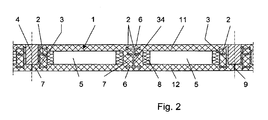
- FIG. 1 consists of the hollow plate element 1 of two spaced apart and mutually parallel plates 11, 12, wherein in FIG. 1 the top view on the upper plate 11 is shown. It can be seen that in the central region of the hollow plate element 1, two mutually parallel and mutually spaced clamping cables 2 are guided, in the central region of a likewise parallel guided web plate 3 is guided.
- FIG. 2 shows that with the help of a filling body 4, the connection to the adjacent hollow plate element 1 is achieved.
- the hollow plate member 1 has in the space between the upper and lower plates 11, 12 cavities 5, in which, for example, an insulation 8 is laid. In this cavity 5 and common installation cables, heating and cooling pipes and the like are laid. Likewise, it is provided to lay in the cross section of the lower plate 12 and heating or cooling lines.
- a web plate 3 is laid, which consists essentially of a double-T cross-section.
- This web plate 3 has a vertical leg 34, which extends over a first preferred embodiment over the entire length of the hollow plate element 1.
- this web plate 3 is only partially available.
- a number of head bolts 6 are fixed, each having a head 29 of enlarged cross-section at their outer free ends.
- the head bolts 6 are preferably made of a metal material, as well as the vertical leg 34 of the web plate. 3
- the head bolts 6 are then in this case preferably secured with a weld on the vertical leg 34 of the web plate 3.
- Purpose of this head bolt 6 is to provide a positive connection between the upper plate 11 and the lower plate 12 via the vertical leg 34 of the web plate 3, which is laid in the illustrated embodiment in the region of a concrete web 7.
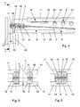
- tensioning cable 2 are each received at the ends of the hollow plate elements 1 in anchor bodies 10.
- Each anchor body 10 consists of the anchor plate 19, through which the cable outline 21, consisting of individual strands 25 is passed. These strands 25 are guided beyond the anchor plate 19 by an anchor bushing 16, deflected there in an arc and engage through a fixing plate 17 and are anchored in a cone receptacle 18. In this way, there is an immovable fixing of the strands 25 of the tensioning cable 2 in the anchor bushing sixteenth
- the adjustment of the bias voltage to the tensioning cable 2 takes place when the two plates are connected and cured according to the specified method. It is then handled with a corresponding pulling tool on the backward strands 25 and the strands are high Tensile force stretched along its longitudinal direction, then turned over and anchored in the cone seat 18 of the anchor plate 16.
- FIGS. 3 and 4 show that the hollow plate member 1 rests at its ends in each case by a construction designed as a double support 13 construction.
- the concrete web 7 is attached in order to enclose the web plate 3 with the anchor bodies 10 arranged thereon on the front, the cable outline 21 of the anchor body 10 is still surrounded by a helical reinforcement 20 in order to absorb splitting tensile forces.
- FIG. 4 Incidentally, it can be seen that the upper edge 23 of the web plate 3 does not extend to the outer edge of the upper plate 11, and also the lower edge 22 of the web plate does not extend to the bottom of the lower plate 12.
- This space is covered with concrete and in the area of the upper and lower plates are according to FIG. 7 Longitudinal and transverse reinforcements 26, 27 arranged.
- FIG. 7 also shows that in the lower plate heating cables 28 are arranged, which can be traversed by a heating or a cooling medium.
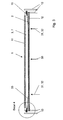
- FIG. 3 shows the basic principle of the invention, from which it can be deduced that essentially the tensioning cable assumes a trapezoidal shape 33 when it is introduced into the lower plate, wherein deflecting saddles 32 are preferably provided at the deflection points 31 in the region of the lower plate, which guides the cable guide of the tensioning cable 2 take there and thus provide the desired trapezoidal shape 33.
- the bias voltage is - as stated in the general description part - adjusted so that there is a zero deflection of the unloaded hollow plate elements 1.
- the arranged in the space between the upper and lower plate web plates 3 then need only record the traffic-related load and deflection of the hollow plate elements 1.
Landscapes
- Engineering & Computer Science (AREA)
- Architecture (AREA)
- Civil Engineering (AREA)
- Structural Engineering (AREA)
- Physics & Mathematics (AREA)
- Electromagnetism (AREA)
- Bridges Or Land Bridges (AREA)
- Panels For Use In Building Construction (AREA)
- Diaphragms For Electromechanical Transducers (AREA)
- Audible-Bandwidth Dynamoelectric Transducers Other Than Pickups (AREA)
Claims (7)
- Procédé pour la fabrication d'un élément formant dalle creuse (1) qui forme une cavité (5) entre des dalles en béton supérieure et inférieure (11, 12) pourvues dans leur zone intérieure d'un certain nombre de câbles de contrainte (2) posés sur l'axe longitudinal de rebords en béton (7), étant précisé qu'il est prévu dans la cavité (5) entre les dalles en béton supérieure et inférieure (11, 12) de l'élément formant dalle creuse (1) plusieurs éléments (3) qui définissent un écartement mutuel et qui sont parallèles, les câbles de contrainte (2) étant posés parallèlement au sens longitudinal desdits éléments (3), caractérisé en ce que les éléments (3) sont constitués par des tôles d'âme (3), étant précisé que chaque câble de contrainte (2) est relié avec une extrémité à la tôle d'âme (3) respective par l'intermédiaire d'un corps d'ancrage (10) tandis que son extrémité opposée est reliée par l'intermédiaire d'un autre corps d'ancrage (10) à l'extrémité, située à cet endroit, de la tôle d'âme (3), et que la fabrication d'un élément formant dalle creuse (1) comporte les étapes qui consistent :- à installer des éléments d'ancrage (6, 16-20) et des selles (32) sur la tôle d'âme (3) ;- à relier les tôles d'âme (3) à la dalle en béton supérieure ou inférieure (11, 12) ;- à insérer des câbles de contrainte (2) parallèlement à la tôle d'âme (3) ;- à relier la dalle en béton supérieure (11) à la dalle en béton inférieure (12) ;- à précontraindre les câbles de contrainte (2) après la liaison et la prise des deux dalles en béton (11, 12), en introduisant une force de contrainte dans le rebord en béton (7), et par l'intermédiaire des tôles d'âme (3) dans les dalles en béton (11, 12).
- Procédé pour la fabrication d'un élément formant dalle creuse (1) selon la revendication 1, caractérisé en ce que le câble de contrainte (2) est ancré avec un fléchissement bombé à la dalle en béton inférieure (12) à l'aide des selles (32) et forme un guidage trapézoïdal du câble de contrainte (2).
- Élément formant dalle creuse (1) fabriqué selon le procédé selon l'une des revendications 1 ou 2 précédentes, caractérisé en ce que sur les côtés frontaux extérieurs dudit élément formant dalle creuse (1), il est seulement prévu des câbles de contrainte (2) individuels, et l'élément formant dalle creuse (1) est raccordé à l'élément formant dalle creuse (1) voisin à l'aide d'un corps de remplissage (4), un joint (9) étant formé au-dessous du corps de remplissage (4), comme joint de séparation entre les éléments formant dalles creuses (1) voisins.
- Élément formant dalle creuse (1) selon la revendication 3, caractérisé en ce que la tôle d'âme (3) présente une section transversale en double T avec une branche verticale (34), la tôle d'âme (3) s'étendant sur toute la longueur de l'élément formant dalle creuse (1).
- Élément formant dalle creuse (1) selon la revendication 4, caractérisé en ce que la branche verticale (34) de la tôle d'âme (3) présente des goujons à tête (6) qui sont espacés dans le sens longitudinal, qui présentent à leur extrémité libre une tête (29) à section plus grande et qui se composent d'un matériau métallique, les goujons à tête (6) étant fixés à la branche verticale (34) à l'aide d'une liaison soudée.
- Élément formant dalle creuse (1) selon la revendication 5, caractérisé en ce que les goujons à tête (6) forment une liaison par complémentarité de forme entre la dalle en béton supérieure (11) et la dalle en béton inférieure (12) dudit élément formant dalle creuse (1) par l'intermédiaire de la branche verticale (34) de la tôle d'âme (3) qui est disposée dans la zone du rebord en béton (7).
- Élément formant dalle creuse (1) selon l'une des revendications 1 à 6 précédentes, caractérisé en ce que le corps d'ancrage (10) comporte une plaque d'ancrage (19) à travers laquelle passe le contour de câble (21) présentant des torons individuels (25), étant précisé que les torons (25) traversent, au-delà de la plaque d'ancrage (19), un manchon d'ancrage (16), sont déviés en courbe, traversent une plaque de fixation (17) et sont ancrés dans un logement conique (18) et forment ainsi une fixation définitive des câbles de contrainte (2) dans le manchon d'ancrage (16).
Applications Claiming Priority (1)
| Application Number | Priority Date | Filing Date | Title |
|---|---|---|---|
| DE102008011689A DE102008011689A1 (de) | 2008-02-28 | 2008-02-28 | Hohlplattenelement mit großer Spannweite und niedriger Höhe |
Publications (2)
| Publication Number | Publication Date |
|---|---|
| EP2096220A1 EP2096220A1 (fr) | 2009-09-02 |
| EP2096220B1 true EP2096220B1 (fr) | 2011-04-13 |
Family
ID=40749821
Family Applications (1)
| Application Number | Title | Priority Date | Filing Date |
|---|---|---|---|
| EP09002839A Active EP2096220B1 (fr) | 2008-02-28 | 2009-02-27 | Elément de plaques creuses préconstraintes |
Country Status (3)
| Country | Link |
|---|---|
| EP (1) | EP2096220B1 (fr) |
| AT (1) | ATE505599T1 (fr) |
| DE (2) | DE102008011689A1 (fr) |
Families Citing this family (1)
| Publication number | Priority date | Publication date | Assignee | Title |
|---|---|---|---|---|
| CN115338973B (zh) * | 2022-09-08 | 2023-07-14 | 山东大学 | 一种钢肋混凝土上翼缘板的正向制作设备及制作方法 |
Family Cites Families (8)
| Publication number | Priority date | Publication date | Assignee | Title |
|---|---|---|---|---|
| GB650634A (en) * | 1948-06-11 | 1951-02-28 | Ariosto Semeraro | Improved method of erecting houses or other structures from prefabricated elements |
| FR2610656B1 (fr) * | 1987-02-11 | 1991-06-21 | Citra | Dispositif pour guider les cables de precontrainte d'un ouvrage de genie civil |
| ES2161199B1 (es) | 2000-05-16 | 2002-07-01 | Sanchez Jaime Enrique Jimenez | Procedimiento de fabricacion de placa alveolar ligera materializada en obra, placa asi obtenida y su aplicacion en viviendas. |
| KR100423757B1 (ko) * | 2001-05-04 | 2004-03-22 | 원대연 | 프리스트레스트 합성 트러스 보 및 그의 제조 방법 |
| AU2003262578A1 (en) * | 2002-08-28 | 2004-03-19 | Carlos Fradera Pellicer | Method of producing a light facade panel for construction, means for the production and installation of same, the light facade panel thus obtained and use thereof |
| DE50302102D1 (de) * | 2002-10-05 | 2006-03-30 | Dywidag Systems Int Gmbh | Stahl-Verbund-Konstruktion für Geschossdecken |
| DE10350082B4 (de) | 2003-10-27 | 2007-02-22 | Rudolph, Hermann, Dipl.-Ing. | Vorgespannte Flachdecke mit Hohldeckenplatten |
| EP1790789A1 (fr) | 2005-11-28 | 2007-05-30 | Bartoli N.V. | Système de construction, poutre, colonne et méthode |
-
2008
- 2008-02-28 DE DE102008011689A patent/DE102008011689A1/de not_active Withdrawn
-
2009
- 2009-02-27 AT AT09002839T patent/ATE505599T1/de active
- 2009-02-27 DE DE502009000516T patent/DE502009000516D1/de active Active
- 2009-02-27 EP EP09002839A patent/EP2096220B1/fr active Active
Also Published As
| Publication number | Publication date |
|---|---|
| ATE505599T1 (de) | 2011-04-15 |
| EP2096220A1 (fr) | 2009-09-02 |
| DE502009000516D1 (de) | 2011-05-26 |
| DE102008011689A1 (de) | 2009-12-10 |
Similar Documents
| Publication | Publication Date | Title |
|---|---|---|
| EP1007809B1 (fr) | Dispositif de renfort pour structures porteuses | |
| EP2912239B1 (fr) | Élément d'armature pour la fabrication d'éléments de construction en béton précontraint, élément de construction en béton et procédé de fabrication | |
| DE112010000467T5 (de) | Scherverstärkungsmaterial des kragträgertyps mit doppeltenverankerungsfunktionen an oberseite und unterseite | |
| EP2646627B1 (fr) | Dispositif permettant de fixer des dalles en béton armé à un système de plancher ou de cloison en béton armé | |
| EP0755473B1 (fr) | Bande a goujons pour barres relevees | |
| DE69410077T2 (de) | Vorgefertigter stahlbetonverbundträger | |
| EP1040238B1 (fr) | Armature de cisaillement pour plafonds plats et profile a goujons correspondant | |
| DE3001309A1 (de) | Tragsystem fuer baukonstruktionen | |
| DE102009013241B4 (de) | Aus einem einstückigen Stahlbauprofil bestehender Träger | |
| EP2239119B1 (fr) | Banc de précontrainte mobile pour éléments en béton précontraint | |
| EP1795667A2 (fr) | Elément d'armature pour structures en béton armé, béton précontraint ou similaires | |
| DE202023105561U1 (de) | Energieaufnehmendes Segment und segmentartige kombinierte knickverhindernde energieaufnehmende Stützstruktur | |
| EP2189586B1 (fr) | Elément de plaque doté d'un renforcement | |
| EP2130984A2 (fr) | Corps de répartition de charge doté d'un système de support de profil | |
| DE102019133999A1 (de) | Anordnung zum Verbinden eines Bauwerkteils mit einem dem Bauwerkteil vorgelagerten Außenteil | |
| EP2096220B1 (fr) | Elément de plaques creuses préconstraintes | |
| EP2459812B1 (fr) | Élément de béton armé à armature formée d'éléments de tôle en z | |
| DE102008033585A1 (de) | Schubdornverbindung | |
| DE19831984C2 (de) | Bauteil mit externen Spanngliedern | |
| EP0796961B1 (fr) | Bétoncellulaire avec système d'armatures | |
| EP0947640A2 (fr) | Armature à haute adhérence | |
| DE102016121713A1 (de) | Segmentbrücke | |
| DE102020114611B3 (de) | Schalungsanordnung | |
| EP2080841A2 (fr) | Elément de pose de dalles en console | |
| EP2241699A2 (fr) | Douille d'ancrage pour l'ancrage d'éléments d'armature prétendus |
Legal Events
| Date | Code | Title | Description |
|---|---|---|---|
| PUAI | Public reference made under article 153(3) epc to a published international application that has entered the european phase |
Free format text: ORIGINAL CODE: 0009012 |
|
| AK | Designated contracting states |
Kind code of ref document: A1 Designated state(s): AT BE BG CH CY CZ DE DK EE ES FI FR GB GR HR HU IE IS IT LI LT LU LV MC MK MT NL NO PL PT RO SE SI SK TR |
|
| AX | Request for extension of the european patent |
Extension state: AL BA RS |
|
| 17P | Request for examination filed |
Effective date: 20100122 |
|
| 17Q | First examination report despatched |
Effective date: 20100216 |
|
| AKX | Designation fees paid |
Designated state(s): AT BE BG CH CY CZ DE DK EE ES FI FR GB GR HR HU IE IS IT LI LT LU LV MC MK MT NL NO PL PT RO SE SI SK TR |
|
| GRAP | Despatch of communication of intention to grant a patent |
Free format text: ORIGINAL CODE: EPIDOSNIGR1 |
|
| GRAS | Grant fee paid |
Free format text: ORIGINAL CODE: EPIDOSNIGR3 |
|
| GRAA | (expected) grant |
Free format text: ORIGINAL CODE: 0009210 |
|
| AK | Designated contracting states |
Kind code of ref document: B1 Designated state(s): AT BE BG CH CY CZ DE DK EE ES FI FR GB GR HR HU IE IS IT LI LT LU LV MC MK MT NL NO PL PT RO SE SI SK TR |
|
| REG | Reference to a national code |
Ref country code: GB Ref legal event code: FG4D Free format text: NOT ENGLISH |
|
| REG | Reference to a national code |
Ref country code: CH Ref legal event code: EP |
|
| REG | Reference to a national code |
Ref country code: IE Ref legal event code: FG4D Free format text: LANGUAGE OF EP DOCUMENT: GERMAN |
|
| REF | Corresponds to: |
Ref document number: 502009000516 Country of ref document: DE Date of ref document: 20110526 Kind code of ref document: P |
|
| REG | Reference to a national code |
Ref country code: DE Ref legal event code: R096 Ref document number: 502009000516 Country of ref document: DE Effective date: 20110526 |
|
| REG | Reference to a national code |
Ref country code: CH Ref legal event code: NV Representative=s name: LUCHS & PARTNER AG PATENTANWAELTE |
|
| REG | Reference to a national code |
Ref country code: NL Ref legal event code: T3 |
|
| LTIE | Lt: invalidation of european patent or patent extension |
Effective date: 20110413 |
|
| PG25 | Lapsed in a contracting state [announced via postgrant information from national office to epo] |
Ref country code: PT Free format text: LAPSE BECAUSE OF FAILURE TO SUBMIT A TRANSLATION OF THE DESCRIPTION OR TO PAY THE FEE WITHIN THE PRESCRIBED TIME-LIMIT Effective date: 20110816 Ref country code: SE Free format text: LAPSE BECAUSE OF FAILURE TO SUBMIT A TRANSLATION OF THE DESCRIPTION OR TO PAY THE FEE WITHIN THE PRESCRIBED TIME-LIMIT Effective date: 20110413 Ref country code: LT Free format text: LAPSE BECAUSE OF FAILURE TO SUBMIT A TRANSLATION OF THE DESCRIPTION OR TO PAY THE FEE WITHIN THE PRESCRIBED TIME-LIMIT Effective date: 20110413 Ref country code: NO Free format text: LAPSE BECAUSE OF FAILURE TO SUBMIT A TRANSLATION OF THE DESCRIPTION OR TO PAY THE FEE WITHIN THE PRESCRIBED TIME-LIMIT Effective date: 20110713 Ref country code: HR Free format text: LAPSE BECAUSE OF FAILURE TO SUBMIT A TRANSLATION OF THE DESCRIPTION OR TO PAY THE FEE WITHIN THE PRESCRIBED TIME-LIMIT Effective date: 20110413 |
|
| REG | Reference to a national code |
Ref country code: IE Ref legal event code: FD4D |
|
| PG25 | Lapsed in a contracting state [announced via postgrant information from national office to epo] |
Ref country code: ES Free format text: LAPSE BECAUSE OF FAILURE TO SUBMIT A TRANSLATION OF THE DESCRIPTION OR TO PAY THE FEE WITHIN THE PRESCRIBED TIME-LIMIT Effective date: 20110724 Ref country code: LV Free format text: LAPSE BECAUSE OF FAILURE TO SUBMIT A TRANSLATION OF THE DESCRIPTION OR TO PAY THE FEE WITHIN THE PRESCRIBED TIME-LIMIT Effective date: 20110413 Ref country code: SI Free format text: LAPSE BECAUSE OF FAILURE TO SUBMIT A TRANSLATION OF THE DESCRIPTION OR TO PAY THE FEE WITHIN THE PRESCRIBED TIME-LIMIT Effective date: 20110413 Ref country code: GR Free format text: LAPSE BECAUSE OF FAILURE TO SUBMIT A TRANSLATION OF THE DESCRIPTION OR TO PAY THE FEE WITHIN THE PRESCRIBED TIME-LIMIT Effective date: 20110714 Ref country code: CY Free format text: LAPSE BECAUSE OF FAILURE TO SUBMIT A TRANSLATION OF THE DESCRIPTION OR TO PAY THE FEE WITHIN THE PRESCRIBED TIME-LIMIT Effective date: 20110413 Ref country code: IS Free format text: LAPSE BECAUSE OF FAILURE TO SUBMIT A TRANSLATION OF THE DESCRIPTION OR TO PAY THE FEE WITHIN THE PRESCRIBED TIME-LIMIT Effective date: 20110813 Ref country code: FI Free format text: LAPSE BECAUSE OF FAILURE TO SUBMIT A TRANSLATION OF THE DESCRIPTION OR TO PAY THE FEE WITHIN THE PRESCRIBED TIME-LIMIT Effective date: 20110413 |
|
| PLBI | Opposition filed |
Free format text: ORIGINAL CODE: 0009260 |
|
| PG25 | Lapsed in a contracting state [announced via postgrant information from national office to epo] |
Ref country code: IE Free format text: LAPSE BECAUSE OF FAILURE TO SUBMIT A TRANSLATION OF THE DESCRIPTION OR TO PAY THE FEE WITHIN THE PRESCRIBED TIME-LIMIT Effective date: 20110413 Ref country code: CZ Free format text: LAPSE BECAUSE OF FAILURE TO SUBMIT A TRANSLATION OF THE DESCRIPTION OR TO PAY THE FEE WITHIN THE PRESCRIBED TIME-LIMIT Effective date: 20110413 Ref country code: EE Free format text: LAPSE BECAUSE OF FAILURE TO SUBMIT A TRANSLATION OF THE DESCRIPTION OR TO PAY THE FEE WITHIN THE PRESCRIBED TIME-LIMIT Effective date: 20110413 |
|
| 26 | Opposition filed |
Opponent name: HERMANN RUDOLPH BAUSTOFFWERK GMBH Effective date: 20120113 |
|
| PG25 | Lapsed in a contracting state [announced via postgrant information from national office to epo] |
Ref country code: PL Free format text: LAPSE BECAUSE OF FAILURE TO SUBMIT A TRANSLATION OF THE DESCRIPTION OR TO PAY THE FEE WITHIN THE PRESCRIBED TIME-LIMIT Effective date: 20110413 Ref country code: SK Free format text: LAPSE BECAUSE OF FAILURE TO SUBMIT A TRANSLATION OF THE DESCRIPTION OR TO PAY THE FEE WITHIN THE PRESCRIBED TIME-LIMIT Effective date: 20110413 |
|
| PLAX | Notice of opposition and request to file observation + time limit sent |
Free format text: ORIGINAL CODE: EPIDOSNOBS2 |
|
| REG | Reference to a national code |
Ref country code: DE Ref legal event code: R026 Ref document number: 502009000516 Country of ref document: DE Effective date: 20120113 |
|
| PG25 | Lapsed in a contracting state [announced via postgrant information from national office to epo] |
Ref country code: IT Free format text: LAPSE BECAUSE OF FAILURE TO SUBMIT A TRANSLATION OF THE DESCRIPTION OR TO PAY THE FEE WITHIN THE PRESCRIBED TIME-LIMIT Effective date: 20110413 |
|
| PLBB | Reply of patent proprietor to notice(s) of opposition received |
Free format text: ORIGINAL CODE: EPIDOSNOBS3 |
|
| PG25 | Lapsed in a contracting state [announced via postgrant information from national office to epo] |
Ref country code: MC Free format text: LAPSE BECAUSE OF NON-PAYMENT OF DUE FEES Effective date: 20120229 |
|
| REG | Reference to a national code |
Ref country code: FR Ref legal event code: ST Effective date: 20121031 |
|
| PG25 | Lapsed in a contracting state [announced via postgrant information from national office to epo] |
Ref country code: FR Free format text: LAPSE BECAUSE OF NON-PAYMENT OF DUE FEES Effective date: 20120229 |
|
| PG25 | Lapsed in a contracting state [announced via postgrant information from national office to epo] |
Ref country code: MK Free format text: LAPSE BECAUSE OF FAILURE TO SUBMIT A TRANSLATION OF THE DESCRIPTION OR TO PAY THE FEE WITHIN THE PRESCRIBED TIME-LIMIT Effective date: 20110413 |
|
| PG25 | Lapsed in a contracting state [announced via postgrant information from national office to epo] |
Ref country code: BG Free format text: LAPSE BECAUSE OF FAILURE TO SUBMIT A TRANSLATION OF THE DESCRIPTION OR TO PAY THE FEE WITHIN THE PRESCRIBED TIME-LIMIT Effective date: 20110713 |
|
| PG25 | Lapsed in a contracting state [announced via postgrant information from national office to epo] |
Ref country code: MT Free format text: LAPSE BECAUSE OF FAILURE TO SUBMIT A TRANSLATION OF THE DESCRIPTION OR TO PAY THE FEE WITHIN THE PRESCRIBED TIME-LIMIT Effective date: 20110413 |
|
| GBPC | Gb: european patent ceased through non-payment of renewal fee |
Effective date: 20130227 |
|
| PG25 | Lapsed in a contracting state [announced via postgrant information from national office to epo] |
Ref country code: GB Free format text: LAPSE BECAUSE OF NON-PAYMENT OF DUE FEES Effective date: 20130227 |
|
| PG25 | Lapsed in a contracting state [announced via postgrant information from national office to epo] |
Ref country code: TR Free format text: LAPSE BECAUSE OF FAILURE TO SUBMIT A TRANSLATION OF THE DESCRIPTION OR TO PAY THE FEE WITHIN THE PRESCRIBED TIME-LIMIT Effective date: 20110413 |
|
| PG25 | Lapsed in a contracting state [announced via postgrant information from national office to epo] |
Ref country code: HU Free format text: LAPSE BECAUSE OF FAILURE TO SUBMIT A TRANSLATION OF THE DESCRIPTION OR TO PAY THE FEE WITHIN THE PRESCRIBED TIME-LIMIT Effective date: 20090227 |
|
| PLBP | Opposition withdrawn |
Free format text: ORIGINAL CODE: 0009264 |
|
| PLBD | Termination of opposition procedure: decision despatched |
Free format text: ORIGINAL CODE: EPIDOSNOPC1 |
|
| REG | Reference to a national code |
Ref country code: DE Ref legal event code: R100 Ref document number: 502009000516 Country of ref document: DE |
|
| PLBM | Termination of opposition procedure: date of legal effect published |
Free format text: ORIGINAL CODE: 0009276 |
|
| STAA | Information on the status of an ep patent application or granted ep patent |
Free format text: STATUS: OPPOSITION PROCEDURE CLOSED |
|
| 27C | Opposition proceedings terminated |
Effective date: 20171223 |
|
| PGFP | Annual fee paid to national office [announced via postgrant information from national office to epo] |
Ref country code: LU Payment date: 20240226 Year of fee payment: 16 |
|
| PGFP | Annual fee paid to national office [announced via postgrant information from national office to epo] |
Ref country code: NL Payment date: 20240220 Year of fee payment: 16 |
|
| PGFP | Annual fee paid to national office [announced via postgrant information from national office to epo] |
Ref country code: AT Payment date: 20240216 Year of fee payment: 16 |
|
| PGFP | Annual fee paid to national office [announced via postgrant information from national office to epo] |
Ref country code: DE Payment date: 20240216 Year of fee payment: 16 Ref country code: CH Payment date: 20240301 Year of fee payment: 16 |
|
| PGFP | Annual fee paid to national office [announced via postgrant information from national office to epo] |
Ref country code: BE Payment date: 20240219 Year of fee payment: 16 |