EP2094440B1 - Precision abrasive machining of work piece surfaces - Google Patents
Precision abrasive machining of work piece surfaces Download PDFInfo
- Publication number
- EP2094440B1 EP2094440B1 EP07862251A EP07862251A EP2094440B1 EP 2094440 B1 EP2094440 B1 EP 2094440B1 EP 07862251 A EP07862251 A EP 07862251A EP 07862251 A EP07862251 A EP 07862251A EP 2094440 B1 EP2094440 B1 EP 2094440B1
- Authority
- EP
- European Patent Office
- Prior art keywords
- tool
- force
- actuator
- work piece
- actual
- Prior art date
- Legal status (The legal status is an assumption and is not a legal conclusion. Google has not performed a legal analysis and makes no representation as to the accuracy of the status listed.)
- Not-in-force
Links
- 238000003754 machining Methods 0.000 title description 7
- 238000000034 method Methods 0.000 claims description 11
- 230000008859 change Effects 0.000 claims description 10
- 230000000717 retained effect Effects 0.000 claims 2
- 238000005498 polishing Methods 0.000 abstract description 15
- 239000000463 material Substances 0.000 abstract description 14
- 230000033001 locomotion Effects 0.000 description 21
- 238000010586 diagram Methods 0.000 description 10
- 239000012212 insulator Substances 0.000 description 10
- 230000007246 mechanism Effects 0.000 description 9
- XUIMIQQOPSSXEZ-UHFFFAOYSA-N Silicon Chemical compound [Si] XUIMIQQOPSSXEZ-UHFFFAOYSA-N 0.000 description 6
- 239000010408 film Substances 0.000 description 6
- 229910052710 silicon Inorganic materials 0.000 description 6
- 239000010703 silicon Substances 0.000 description 6
- 239000011521 glass Substances 0.000 description 5
- 239000010410 layer Substances 0.000 description 4
- 230000004048 modification Effects 0.000 description 4
- 238000012986 modification Methods 0.000 description 4
- 230000008569 process Effects 0.000 description 4
- 239000004065 semiconductor Substances 0.000 description 4
- 239000010409 thin film Substances 0.000 description 3
- 229910000577 Silicon-germanium Inorganic materials 0.000 description 2
- 239000013078 crystal Substances 0.000 description 2
- 238000005516 engineering process Methods 0.000 description 2
- 230000035945 sensitivity Effects 0.000 description 2
- 239000000758 substrate Substances 0.000 description 2
- JBRZTFJDHDCESZ-UHFFFAOYSA-N AsGa Chemical compound [As]#[Ga] JBRZTFJDHDCESZ-UHFFFAOYSA-N 0.000 description 1
- LEVVHYCKPQWKOP-UHFFFAOYSA-N [Si].[Ge] Chemical compound [Si].[Ge] LEVVHYCKPQWKOP-UHFFFAOYSA-N 0.000 description 1
- 238000005299 abrasion Methods 0.000 description 1
- 238000007792 addition Methods 0.000 description 1
- 230000015572 biosynthetic process Effects 0.000 description 1
- 239000000919 ceramic Substances 0.000 description 1
- 230000006835 compression Effects 0.000 description 1
- 238000007906 compression Methods 0.000 description 1
- 238000010276 construction Methods 0.000 description 1
- 238000013461 design Methods 0.000 description 1
- 238000007516 diamond turning Methods 0.000 description 1
- 238000006073 displacement reaction Methods 0.000 description 1
- 230000000694 effects Effects 0.000 description 1
- 239000000835 fiber Substances 0.000 description 1
- 229910052732 germanium Inorganic materials 0.000 description 1
- GNPVGFCGXDBREM-UHFFFAOYSA-N germanium atom Chemical compound [Ge] GNPVGFCGXDBREM-UHFFFAOYSA-N 0.000 description 1
- 230000006872 improvement Effects 0.000 description 1
- 238000011065 in-situ storage Methods 0.000 description 1
- 239000011810 insulating material Substances 0.000 description 1
- 239000011159 matrix material Substances 0.000 description 1
- 238000005259 measurement Methods 0.000 description 1
- 229910021421 monocrystalline silicon Inorganic materials 0.000 description 1
- 230000003287 optical effect Effects 0.000 description 1
- 229920001296 polysiloxane Polymers 0.000 description 1
- HBMJWWWQQXIZIP-UHFFFAOYSA-N silicon carbide Chemical compound [Si+]#[C-] HBMJWWWQQXIZIP-UHFFFAOYSA-N 0.000 description 1
- 238000006467 substitution reaction Methods 0.000 description 1
- 239000002344 surface layer Substances 0.000 description 1
- 238000012360 testing method Methods 0.000 description 1
- 235000012431 wafers Nutrition 0.000 description 1
Images


Classifications
-
- B—PERFORMING OPERATIONS; TRANSPORTING
- B24—GRINDING; POLISHING
- B24B—MACHINES, DEVICES, OR PROCESSES FOR GRINDING OR POLISHING; DRESSING OR CONDITIONING OF ABRADING SURFACES; FEEDING OF GRINDING, POLISHING, OR LAPPING AGENTS
- B24B49/00—Measuring or gauging equipment for controlling the feed movement of the grinding tool or work; Arrangements of indicating or measuring equipment, e.g. for indicating the start of the grinding operation
- B24B49/16—Measuring or gauging equipment for controlling the feed movement of the grinding tool or work; Arrangements of indicating or measuring equipment, e.g. for indicating the start of the grinding operation taking regard of the load
-
- B—PERFORMING OPERATIONS; TRANSPORTING
- B24—GRINDING; POLISHING
- B24B—MACHINES, DEVICES, OR PROCESSES FOR GRINDING OR POLISHING; DRESSING OR CONDITIONING OF ABRADING SURFACES; FEEDING OF GRINDING, POLISHING, OR LAPPING AGENTS
- B24B13/00—Machines or devices designed for grinding or polishing optical surfaces on lenses or surfaces of similar shape on other work; Accessories therefor
- B24B13/01—Specific tools, e.g. bowl-like; Production, dressing or fastening of these tools
-
- B—PERFORMING OPERATIONS; TRANSPORTING
- B24—GRINDING; POLISHING
- B24B—MACHINES, DEVICES, OR PROCESSES FOR GRINDING OR POLISHING; DRESSING OR CONDITIONING OF ABRADING SURFACES; FEEDING OF GRINDING, POLISHING, OR LAPPING AGENTS
- B24B7/00—Machines or devices designed for grinding plane surfaces on work, including polishing plane glass surfaces; Accessories therefor
- B24B7/20—Machines or devices designed for grinding plane surfaces on work, including polishing plane glass surfaces; Accessories therefor characterised by a special design with respect to properties of the material of non-metallic articles to be ground
- B24B7/22—Machines or devices designed for grinding plane surfaces on work, including polishing plane glass surfaces; Accessories therefor characterised by a special design with respect to properties of the material of non-metallic articles to be ground for grinding inorganic material, e.g. stone, ceramics, porcelain
- B24B7/228—Machines or devices designed for grinding plane surfaces on work, including polishing plane glass surfaces; Accessories therefor characterised by a special design with respect to properties of the material of non-metallic articles to be ground for grinding inorganic material, e.g. stone, ceramics, porcelain for grinding thin, brittle parts, e.g. semiconductors, wafers
Definitions
- the present invention relates generally to machine control and, more particularly, concerns a method and a system for precision machining or finishing of article surfaces. It finds application, among other uses, in polishing of the semiconductor layer of semiconductor-on-insulator structures.
- Silicon-on-insulator technology is becoming increasingly important for high performance thin film transistors, solar cells, and display, such as active matrix displays.
- Silicon-on-insulator wafers consist of a thin layer of substantially single crystal silicon (generally 0.1-0.3 microns in thickness but, in some cases, as thick as 5 microns) on an insulating material.
- TFT thin film transistor
- silicon-on-glass (SiOG) substrates are subjected to a machining process that thins the surface film.
- This is commonly performed by "deterministic polishing," an abrading process performed by a tool that has a substantially smaller polishing contact zone than the component being machined.
- This type of process is typically performed today by the use of ultra-precise optical lens polishing machines, a well-known source of which is Zeeko Limited of Coalville, Leicestershire, UK.
- a machine of this type is disclosed in U.S. Patent No. 6,796,877 , entitled ABRADING MACHINE and issued to Bingham et al. On September 28, 2004.
- precision movement between a machine tool and work piece is provided in three Cartesian coordinates, in order to achieve machining of the entire surface.
- the machining tool of the type disclosed in U.S. Patent No. 6,796,877 may be referred to herein as a bonnet/pad machine, and is illustrated schematically in FIG. 1 .
- the tool 10 has a generally cylindrical body 12 and a working head or bonnet 14 which is internally pressurized to a predetermined pressure.
- the bonnet may be a partially spherical or bulbous, fiber reinforced rubber diaphragm.
- a polishing pad 16 is bonded onto the surface of bonnet 14. In operation, the pad 16 is applied to a surface of the component being machined and is rotated about an axis of rotation A, in order to abrade the surface.
- the tool Prior to use, the tool must be calibrated to the work piece surface to be machined.
- the pad 16 is touched to the surface at a number of points in a predetermined pattern.
- Tool 10 is provided with a positioning mechanism 19 providing precision movement along three axes and the axial movement corresponds to the Z-axis control.
- bonnet 14 In performing the calibration, when the pad 16 is touched to one of the calibration points on the surface, bonnet 14 is moved axially until a predetermined force is sensed by a sensor 18 provided in tool 10. This assures consistency of contact.
- tool movement can be controlled to assure that the bonnet will remain in a plane or other appropriate contour corresponding to the intended finished shape of the surface to be machined.
- bonnet 14 In addition, an appropriate axial spacing of bonnet 14 relative to the surface to be polished will be maintained. This is normally an interference spacing that would place the front of the bonnet past the surface of the work piece, causing compression of the bonnet against the surface.
- the actual machining process is then performed by rotating bonnet 14 and simultaneously moving it in a predetermined scanning pattern along a contour (e.g., a plane) relative to the work piece surface to be machined.
- a contour e.g., a plane
- polishing spot size is controlled by the amount of force between the bonnet and the surface being machined, which results from its interference contact with the surface to be polished. All of these parameters are well understood, and current polishing practice closely controls them.
- the relative spacing between a bonnet/pad type tool and the surface of the work piece is controlled dynamically so that the area of the abrasive pad in contact with the surface of the work piece (also referred to herein as "spot size") remains constant, thereby eliminating spot size variations and the accompanying variations in material removal, which produce surface height fluctuations.
- spot size variation results from various sources including radial error motion of the pad. For a given internal pressure of the tool, the spot size will vary in relationship to the actual axial position between the tool and the work piece surface.
- the force between the tool and the surface of the work piece is sensed and the axial spacing between the tool and the surface of the work piece is controlled in reverse sense to the force variation, in order to compensate for changes in spot size.
- dynamic real time control is exercised, for example, by using a server control subsystem.
- the variation of a parameter which affects spot size is measured prior to use.
- radial error motion of the pad as it rotates may be measured and stored.
- a time varying adjustment in the distance between the tool and the surface of the work piece is then made, as the pad rotates. That distance adjustment compensates for radial error motion, producing a uniform spot size.
- the distance between the tool and work piece surface is controlled by axial movement of the tool.
- the work table supporting the work piece is itself has at least one, and optionally a plurality of actuator/position-sensor pairs spaced in a two dimensional pattern under the table.
- the actuators are controlled to adjust table elevation to change the distance between the tool and work piece so as to compensate for spot size variation. This permits not only control of the spacing between the tool and the work piece surface, but also the tilt of the work piece surface in three dimensions to control orthogonality.
- FIG. 1 is a schematic diagram illustrating a bonnet/pad type abrasive polishing tool
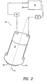
- FIG. 2 is a schematic/block diagram representing a first embodiment in accordance with the present invention in which dynamic servo control is provided of the distance between the tool and the work piece surface in relationship to the force therebetween;
- FIG. 3 is a functional block diagram representing the structure and operation control of the servo control subsystem 32 of FIG. 2 ;
- FIG. 4 is a schematic/block diagram representing a variation of the first embodiment in accordance with the present invention which achieves high speed operation
- FIG. 5 is a flow chart illustrating the process performed in accordance with a second embodiment in accordance with the present invention.
- FIG. 6 is a schematic diagram illustrating a third embodiment in accordance with the present invention.
- FIG. 7 is a block diagram illustrates how spacing control is achieved in accordance with the present embodiment.
- FIG. 2 is a schematic/block diagram illustrating a first embodiment in accordance with the present invention. Specifically, there is disclosed a tool 10 as in FIG. 1 in combination with a control subsystem 32, which controls the spacing between tool 10 and the surface of a work piece in relationship to the force between them.
- the work piece may be a silicon-on-insulator (SOI) structure, such as silicon-on-glass (SOG).
- SOI silicon-on-insulator
- SOG silicon-on-insulator
- SiC silicon carbide
- Ge germanium
- GaAs gallium arsenide
- GaP GaP
- InP InP
- other insulator materials may be employed for practicing the invention, including, but not limited to, various well known silicones and ceramics. Methods and apparatus in accordance with the invention may also find substantially broader application to industry, for example to ultra-precise lens polishing and other surface machining technologies.
- the tool is constructed to have a precisely controlled pressure inside the bonnet 14.
- a portion of the pad 16 is flattened against the surface and, upon rotation, will interact abrasively with the work piece surface to remove material.
- This flattened portion has been referred to herein, as the "spot size," and material removal will vary as the square of the spot size (i.e., its area).
- the spot size changes during rotation of the tool, for example, owing to radial error motion, the effective spot size during rotation of the tool is increased, resulting in more material removal than expected. It will also result in the force between the tool and work piece being greater than expected.
- the Z-axis control of positioning mechanism 19 of tool 10 moves the body 12 along the axis A in FIG. 2 .
- the tool 10 is positioned relative to the surface of the work piece, so that the force between them, as sensed by sensor 18, is that force necessary to produce the desired spot size.
- This "reference force” is stored in the form of a reference force signal 34, and it is applied as an input to control subsystem 32.
- sensor 18 senses the force between body 12 and the surface of the work piece and produces a signal representing that force, which is applied as a second input to control subsystem 32.
- Control subsystem 32 then produces a control signal which operates the Z-axis control of positioning mechanism 19 to adjust the distance between body 12 and the surface of the work piece so as to compensate for force variations sensed by sensor 18.
- the sensor 18 may be a load cell which is mounted inside tool 10. However, a load cell requires relative motion in order to provide a measurement of force has a somewhat limited sensitivity.
- a piezoelectric stack force sensor which is highly rigid and requires orders of magnitude less displacement than a typical load cell in order to produce a signal, may be used in place of sensor 18, in order to gain an improvement in sensitivity.
- FIG. 3 is a functional block diagram representing the structure and operation of control subsystem 32.
- Subsystem 32 itself, is modeled herein as an operational amplifier 24 and a bandwidth filter 22. This has been done for convenience of explanation, and those skilled in the art will understand that this type of servo control system is typically much more complex.
- the output signal of force sensor 18 and the force reference signal 34 are applied differentially to amplifier 24.
- the output signal of amplifier 24 passes through the bandwidth filter 22 and is then applied to the Z-axis control of positioning mechanism 19.
- control subsystem 32 is similar to that of an operational amplifier, in the sense that it produces an output signal that will cause the Z-axis motion to make the force sensor 18 signal equal the reference signal 34.
- the Z-axis motion changes the distance between body 12 and the surface of the work piece so as to cancel the change in spot size.
- Control subsystem 32 compensates for many and possibly all variations in spot size.
- the sources of such variations include bonnet radial error motion, bonnet geometry creep, thickness and flatness variations in the work piece, and machine orthogonality and axis straightness errors.
- Filter 22 represents the design bandwidth of control subsystem 32, and its bandwidth will depend upon the application and the particular machine used.
- the bonnet rotational speed is typically around 200 rpm (3.3 Hz).
- the bandwidth of filter 32 would need to be in excess of 33 Hz. If the bonnet 14 were rotated at its maximum speed of 2,000 rpm, compensation for all ripple error motions would require a bandwidth in excess of 330 Hz. This may not be achievable with a typical positioning mechanism that has a high mass in the Z-axis direction.
- a second modification is made to the first embodiment.
- the modification is made to tool 10 of FIG. 2 to produce a tool 10'.
- the modification comprises mounting a linear actuator 30 on body 12 in order to achieve small axial movements thereof.
- the actuator 30 is of very low mass in order to achieve the positioning bandwidth required for high speed rotation.
- actuator 30 is a piezoelectric actuator stack mounted on a spindle 13 for body 12.
- flexible mounts 20, 20 which are compliant in only the axial direction, an extremely low mass construction is obtained.
- a voice coil or a linear motor could be used in place of the piezoelectric crystal stack.
- FIG. 5 is a flow chart illustrating the process of a second embodiment in accordance with the present invention.
- tool 10 or 10' is operated to compensate for spot size variations without using a servo control system.
- Periodically (e.g., daily) positioning mechanism 19 is subjected to a learning operation. This involves an initial step of setting tool 10 to a reference rotational orientation and setting the force between tool 10 and the work piece so as to create the desired spot size. This step is depicted in block 50.
- the angular orientation of body 12 is then incremented by rotating the body about axis A by a predetermined amount (block 52).
- the tool to work piece spacing is then adjusted to remove any change that may have occurred in the force sense by sensor 18 (block 54) and the change in spacing is stored (block 56).
- FIG. 6 is a schematic diagram illustrating a third embodiment in accordance with the present invention.
- the work piece W is supported on a table T with the tool 10' positioned over the surface S of the work piece W.
- tool 10 would be scanned with respect to the surface S. This could be achieved by translating the tool 10 making use of its positioning system 19 (see FIG. 19) and/or translating the table T.
- Below the table T there are provided a plurality of distance sensor/actuator pairs P each including a sensor 60 and a linear actuator 62. In this embodiment, there are three such pairs P, and they are in a triangular arrangement.
- the tool 10 is used to orthogonalize the table in the usual manner.
- the tool 10 is positioned over the surface S, for example, over the left most pair P, and using its positioning mechanism 19 the distance between tool 10 and surface S is adjusted until sensor 18 senses a predefined force. Thereafter, tool 10 may be positioned over each of the pairs P in turn and the respective actuator 62 is operated to raise or lower the table T until sensor 18 once again measures the desired force.
- table T is orthogonalized. That is, the operating plane of tool 10 is parallel to the plane of table T.
- the work piece W is placed upon the table, tool 10 is positioned over one of the pairs P, and the distance between tool 10 and surface S is adjusted until sensor 18 reads a force corresponding to the desired spot size. Polishing may then begin.
- the force measured by sensor 18 is monitored constantly and the distance between surface S and tool 10 is adjusted to compensate for changes in this force.
- the actuators 62 of pairs P are operated to achieve the space adjustment.
- FIG. 7 illustrates how spacing control is achieved in accordance with the present embodiment.
- a signal corresponding to that force is saved as a reference force 34, as in FIG. 2 .
- Sensor 18 measures the force between tool 10 and surface S as the tool progresses over the surface S, and all actuators 62 are adjusted simultaneously to change the spacing between tool 10 and surface S so as to compensate for any change in force, as was the case in FIG. 2 .
- the orthogonality of table T will be maintained.
- this embodiment not only is there compensation for spot size variations due to tool 10, but also for spot size variations due to orthogonality errors of table T.
- Control subsystem 32 is substantially identical to the correspondingly numbered subsystem in FIG. 2 , and actuators 62 may be load cells, piezoelectric crystal stack actuators, voice coils, linear motors, and the like.
- the sensors 60 are linear transducers, for example, a capacitance gage. They are provided to insure that each actuator moves table T by precisely the same amount.
Landscapes
- Engineering & Computer Science (AREA)
- Mechanical Engineering (AREA)
- Chemical & Material Sciences (AREA)
- Ceramic Engineering (AREA)
- Inorganic Chemistry (AREA)
- Finish Polishing, Edge Sharpening, And Grinding By Specific Grinding Devices (AREA)
- Constituent Portions Of Griding Lathes, Driving, Sensing And Control (AREA)
Applications Claiming Priority (2)
| Application Number | Priority Date | Filing Date | Title |
|---|---|---|---|
| US87200906P | 2006-11-30 | 2006-11-30 | |
| PCT/US2007/024417 WO2008066801A1 (en) | 2006-11-30 | 2007-11-26 | Precision abrasive machining of work piece surfaces |
Publications (2)
| Publication Number | Publication Date |
|---|---|
| EP2094440A1 EP2094440A1 (en) | 2009-09-02 |
| EP2094440B1 true EP2094440B1 (en) | 2010-04-21 |
Family
ID=39291898
Family Applications (1)
| Application Number | Title | Priority Date | Filing Date |
|---|---|---|---|
| EP07862251A Not-in-force EP2094440B1 (en) | 2006-11-30 | 2007-11-26 | Precision abrasive machining of work piece surfaces |
Country Status (7)
| Country | Link |
|---|---|
| US (1) | US7831327B2 (ko) |
| EP (1) | EP2094440B1 (ko) |
| JP (1) | JP5469461B2 (ko) |
| KR (1) | KR20090087943A (ko) |
| CN (1) | CN101541475B (ko) |
| DE (1) | DE602007006051D1 (ko) |
| WO (1) | WO2008066801A1 (ko) |
Families Citing this family (8)
| Publication number | Priority date | Publication date | Assignee | Title |
|---|---|---|---|---|
| CN102825543B (zh) * | 2012-09-18 | 2014-09-03 | 厦门大学 | 一种用于气囊式抛光的气囊抛光头 |
| CN103056772A (zh) * | 2012-12-25 | 2013-04-24 | 北京工业大学 | 一种基于负柔度原理的磨床刚度补偿方法 |
| CN104625960B (zh) * | 2015-02-06 | 2017-09-19 | 苏州富强科技有限公司 | 具有驱动组件的抛光机 |
| CN106239312B (zh) * | 2016-08-02 | 2018-04-10 | 中国科学院长春光学精密机械与物理研究所 | 一种基于平行四边形机构的磨头连接装置 |
| CN108161646A (zh) * | 2018-01-11 | 2018-06-15 | 沈阳仪表科学研究院有限公司 | 非球面光学元件的智能柔性抛光方法及其所采用的智能柔性抛光装置 |
| CN109062013B (zh) * | 2018-09-06 | 2023-06-06 | 重庆科技学院 | 一种光刻机小工件卡具 |
| CN111958487A (zh) * | 2020-08-27 | 2020-11-20 | 德屹智能科技(扬州)有限公司 | 一种异形示教调试工具及加工设备 |
| CN114178912A (zh) * | 2021-12-23 | 2022-03-15 | 四川慧丰精制科技有限责任公司 | 一种气囊抛光方法及抛光装置 |
Family Cites Families (19)
| Publication number | Priority date | Publication date | Assignee | Title |
|---|---|---|---|---|
| US4679271A (en) * | 1986-03-14 | 1987-07-14 | Tennant Company | Automatic tool force compensator for a surface maintenance machine |
| JPH04244373A (ja) * | 1991-01-30 | 1992-09-01 | Hitachi Ltd | 研磨方法及び研磨装置 |
| JP3304994B2 (ja) * | 1991-08-30 | 2002-07-22 | キヤノン株式会社 | 研磨方法および研磨装置 |
| GB9512262D0 (en) * | 1995-06-16 | 1995-08-16 | Bingham Richard G | Tool for computer-controlled machine for optical polishing and figuring |
| DE19635831A1 (de) * | 1996-09-04 | 1998-03-05 | Hell Ag Linotype | Verfahren und Einrichtung zur Steuerung eines Gravierorgans |
| US6183354B1 (en) * | 1996-11-08 | 2001-02-06 | Applied Materials, Inc. | Carrier head with a flexible membrane for a chemical mechanical polishing system |
| US5951370A (en) * | 1997-10-02 | 1999-09-14 | Speedfam-Ipec Corp. | Method and apparatus for monitoring and controlling the flatness of a polishing pad |
| US5980368A (en) * | 1997-11-05 | 1999-11-09 | Aplex Group | Polishing tool having a sealed fluid chamber for support of polishing pad |
| US6165057A (en) * | 1998-05-15 | 2000-12-26 | Gill, Jr.; Gerald L. | Apparatus for localized planarization of semiconductor wafer surface |
| CN100372648C (zh) * | 1998-12-01 | 2008-03-05 | 伦敦大学学院 | 抛光的设备和方法 |
| US6517414B1 (en) * | 2000-03-10 | 2003-02-11 | Appied Materials, Inc. | Method and apparatus for controlling a pad conditioning process of a chemical-mechanical polishing apparatus |
| JP2001260020A (ja) * | 2000-03-16 | 2001-09-25 | Canon Inc | 加圧力可変研磨装置 |
| US6506105B1 (en) * | 2000-05-12 | 2003-01-14 | Multi-Planar Technologies, Inc. | System and method for pneumatic diaphragm CMP head having separate retaining ring and multi-region wafer pressure control |
| US6558232B1 (en) * | 2000-05-12 | 2003-05-06 | Multi-Planar Technologies, Inc. | System and method for CMP having multi-pressure zone loading for improved edge and annular zone material removal control |
| US6569771B2 (en) * | 2001-10-31 | 2003-05-27 | United Microelectronics Corp. | Carrier head for chemical mechanical polishing |
| US7574947B2 (en) * | 2002-05-29 | 2009-08-18 | Massachusetts Institute Of Technology | Rotary fast tool servo system and methods |
| US7176528B2 (en) * | 2003-02-18 | 2007-02-13 | Corning Incorporated | Glass-based SOI structures |
| US7312154B2 (en) * | 2005-12-20 | 2007-12-25 | Corning Incorporated | Method of polishing a semiconductor-on-insulator structure |
| US20070246450A1 (en) * | 2006-04-21 | 2007-10-25 | Cady Raymond C | High temperature anodic bonding apparatus |
-
2007
- 2007-11-26 KR KR1020097013725A patent/KR20090087943A/ko not_active Application Discontinuation
- 2007-11-26 DE DE602007006051T patent/DE602007006051D1/de active Active
- 2007-11-26 JP JP2009539284A patent/JP5469461B2/ja not_active Expired - Fee Related
- 2007-11-26 WO PCT/US2007/024417 patent/WO2008066801A1/en active Application Filing
- 2007-11-26 CN CN2007800443915A patent/CN101541475B/zh not_active Expired - Fee Related
- 2007-11-26 EP EP07862251A patent/EP2094440B1/en not_active Not-in-force
- 2007-11-30 US US11/998,691 patent/US7831327B2/en not_active Expired - Fee Related
Also Published As
| Publication number | Publication date |
|---|---|
| JP2010511520A (ja) | 2010-04-15 |
| DE602007006051D1 (de) | 2010-06-02 |
| JP5469461B2 (ja) | 2014-04-16 |
| CN101541475B (zh) | 2011-03-16 |
| KR20090087943A (ko) | 2009-08-18 |
| CN101541475A (zh) | 2009-09-23 |
| US7831327B2 (en) | 2010-11-09 |
| US20080132148A1 (en) | 2008-06-05 |
| WO2008066801A1 (en) | 2008-06-05 |
| EP2094440A1 (en) | 2009-09-02 |
Similar Documents
| Publication | Publication Date | Title |
|---|---|---|
| EP2094440B1 (en) | Precision abrasive machining of work piece surfaces | |
| KR100938484B1 (ko) | 정밀기계가공장치 및 정밀기계가공방법 | |
| US6077155A (en) | Polishing device and correcting method therefor | |
| US6428389B2 (en) | Polishing apparatus | |
| US6237452B1 (en) | Precision high speed turning machine | |
| JP6862764B2 (ja) | 研削装置およびこれを用いる転がり軸受の製造方法 | |
| JP2006513050A (ja) | 物体表面の高精密加工、特に半導体基板の研磨及びラップ加工方法及び装置 | |
| JPH0929598A (ja) | 非球面形状物体の加工装置 | |
| JP2001219327A (ja) | 触覚フィードバックシステム | |
| JPH0253557A (ja) | 非球面形状物体の加工方法及び加工装置 | |
| JPH01193172A (ja) | 基板上の薄膜の研磨方法 | |
| JPH09150355A (ja) | 研削盤 | |
| JP4762194B2 (ja) | 加工装置、および加工方法 | |
| JP2000337375A (ja) | 静圧気体軸受装置 | |
| JPH04244373A (ja) | 研磨方法及び研磨装置 | |
| JP2004160565A (ja) | 研磨方法および形状可変研磨工具装置 | |
| JPH0623663A (ja) | 超平滑化非接触研磨方法および装置 | |
| JPH04305924A (ja) | 半導体基板製造装置 | |
| KR100608270B1 (ko) | 초정밀 가공에서의 공구 윤곽도 보상방법 | |
| JPH0557520A (ja) | 加工装置 | |
| JP2001326203A (ja) | 超平坦化加工装置 | |
| JPH1110498A (ja) | 固体アクチュエータを用いた面振れ修正機構を持つ加工装置 | |
| JP2003019665A (ja) | 加工装置及び加工方法 | |
| Jones | Fabrication of Large Off-axis Optics | |
| JPH11221763A (ja) | 研削方法および研削装置 |
Legal Events
| Date | Code | Title | Description |
|---|---|---|---|
| PUAI | Public reference made under article 153(3) epc to a published international application that has entered the european phase |
Free format text: ORIGINAL CODE: 0009012 |
|
| 17P | Request for examination filed |
Effective date: 20090305 |
|
| AK | Designated contracting states |
Kind code of ref document: A1 Designated state(s): AT BE BG CH CY CZ DE DK EE ES FI FR GB GR HU IE IS IT LI LT LU LV MC MT NL PL PT RO SE SI SK TR |
|
| RIN1 | Information on inventor provided before grant (corrected) |
Inventor name: STOCKER, MARK A |
|
| GRAP | Despatch of communication of intention to grant a patent |
Free format text: ORIGINAL CODE: EPIDOSNIGR1 |
|
| RBV | Designated contracting states (corrected) |
Designated state(s): AT BE BG CH CY CZ DE DK EE ES FI FR GB GR HU IE IS IT LI LT LU LV MC MT NL PL PT RO SE SI SK TR |
|
| GRAS | Grant fee paid |
Free format text: ORIGINAL CODE: EPIDOSNIGR3 |
|
| DAX | Request for extension of the european patent (deleted) | ||
| GRAA | (expected) grant |
Free format text: ORIGINAL CODE: 0009210 |
|
| RBV | Designated contracting states (corrected) |
Designated state(s): DE FR GB |
|
| AK | Designated contracting states |
Kind code of ref document: B1 Designated state(s): DE FR GB |
|
| REG | Reference to a national code |
Ref country code: GB Ref legal event code: FG4D |
|
| REF | Corresponds to: |
Ref document number: 602007006051 Country of ref document: DE Date of ref document: 20100602 Kind code of ref document: P |
|
| RIN2 | Information on inventor provided after grant (corrected) |
Inventor name: STOCKER, MARK ANDREW |
|
| PLBE | No opposition filed within time limit |
Free format text: ORIGINAL CODE: 0009261 |
|
| STAA | Information on the status of an ep patent application or granted ep patent |
Free format text: STATUS: NO OPPOSITION FILED WITHIN TIME LIMIT |
|
| 26N | No opposition filed |
Effective date: 20110124 |
|
| REG | Reference to a national code |
Ref country code: DE Ref legal event code: R119 Ref document number: 602007006051 Country of ref document: DE Effective date: 20110601 Ref country code: DE Ref legal event code: R119 Ref document number: 602007006051 Country of ref document: DE Effective date: 20110531 |
|
| GBPC | Gb: european patent ceased through non-payment of renewal fee |
Effective date: 20111126 |
|
| PG25 | Lapsed in a contracting state [announced via postgrant information from national office to epo] |
Ref country code: GB Free format text: LAPSE BECAUSE OF NON-PAYMENT OF DUE FEES Effective date: 20111126 |
|
| PG25 | Lapsed in a contracting state [announced via postgrant information from national office to epo] |
Ref country code: DE Free format text: LAPSE BECAUSE OF NON-PAYMENT OF DUE FEES Effective date: 20110531 |
|
| REG | Reference to a national code |
Ref country code: FR Ref legal event code: PLFP Year of fee payment: 9 |
|
| PGFP | Annual fee paid to national office [announced via postgrant information from national office to epo] |
Ref country code: FR Payment date: 20151117 Year of fee payment: 9 |
|
| REG | Reference to a national code |
Ref country code: FR Ref legal event code: ST Effective date: 20170731 |
|
| PG25 | Lapsed in a contracting state [announced via postgrant information from national office to epo] |
Ref country code: FR Free format text: LAPSE BECAUSE OF NON-PAYMENT OF DUE FEES Effective date: 20161130 |