EP2094440B1 - Precision abrasive machining of work piece surfaces - Google Patents
Precision abrasive machining of work piece surfaces Download PDFInfo
- Publication number
- EP2094440B1 EP2094440B1 EP07862251A EP07862251A EP2094440B1 EP 2094440 B1 EP2094440 B1 EP 2094440B1 EP 07862251 A EP07862251 A EP 07862251A EP 07862251 A EP07862251 A EP 07862251A EP 2094440 B1 EP2094440 B1 EP 2094440B1
- Authority
- EP
- European Patent Office
- Prior art keywords
- tool
- force
- actuator
- work piece
- actual
- Prior art date
- Legal status (The legal status is an assumption and is not a legal conclusion. Google has not performed a legal analysis and makes no representation as to the accuracy of the status listed.)
- Expired - Fee Related
Links
Images


Classifications
-
- B—PERFORMING OPERATIONS; TRANSPORTING
- B24—GRINDING; POLISHING
- B24B—MACHINES, DEVICES, OR PROCESSES FOR GRINDING OR POLISHING; DRESSING OR CONDITIONING OF ABRADING SURFACES; FEEDING OF GRINDING, POLISHING, OR LAPPING AGENTS
- B24B49/00—Measuring or gauging equipment for controlling the feed movement of the grinding tool or work; Arrangements of indicating or measuring equipment, e.g. for indicating the start of the grinding operation
- B24B49/16—Measuring or gauging equipment for controlling the feed movement of the grinding tool or work; Arrangements of indicating or measuring equipment, e.g. for indicating the start of the grinding operation taking regard of the load
-
- B—PERFORMING OPERATIONS; TRANSPORTING
- B24—GRINDING; POLISHING
- B24B—MACHINES, DEVICES, OR PROCESSES FOR GRINDING OR POLISHING; DRESSING OR CONDITIONING OF ABRADING SURFACES; FEEDING OF GRINDING, POLISHING, OR LAPPING AGENTS
- B24B13/00—Machines or devices designed for grinding or polishing optical surfaces on lenses or surfaces of similar shape on other work; Accessories therefor
- B24B13/01—Specific tools, e.g. bowl-like; Production, dressing or fastening of these tools
-
- B—PERFORMING OPERATIONS; TRANSPORTING
- B24—GRINDING; POLISHING
- B24B—MACHINES, DEVICES, OR PROCESSES FOR GRINDING OR POLISHING; DRESSING OR CONDITIONING OF ABRADING SURFACES; FEEDING OF GRINDING, POLISHING, OR LAPPING AGENTS
- B24B7/00—Machines or devices designed for grinding plane surfaces on work, including polishing plane glass surfaces; Accessories therefor
- B24B7/20—Machines or devices designed for grinding plane surfaces on work, including polishing plane glass surfaces; Accessories therefor characterised by a special design with respect to properties of the material of non-metallic articles to be ground
- B24B7/22—Machines or devices designed for grinding plane surfaces on work, including polishing plane glass surfaces; Accessories therefor characterised by a special design with respect to properties of the material of non-metallic articles to be ground for grinding inorganic material, e.g. stone, ceramics, porcelain
- B24B7/228—Machines or devices designed for grinding plane surfaces on work, including polishing plane glass surfaces; Accessories therefor characterised by a special design with respect to properties of the material of non-metallic articles to be ground for grinding inorganic material, e.g. stone, ceramics, porcelain for grinding thin, brittle parts, e.g. semiconductors, wafers
Definitions
- the present invention relates generally to machine control and, more particularly, concerns a method and a system for precision machining or finishing of article surfaces. It finds application, among other uses, in polishing of the semiconductor layer of semiconductor-on-insulator structures.
- Silicon-on-insulator technology is becoming increasingly important for high performance thin film transistors, solar cells, and display, such as active matrix displays.
- Silicon-on-insulator wafers consist of a thin layer of substantially single crystal silicon (generally 0.1-0.3 microns in thickness but, in some cases, as thick as 5 microns) on an insulating material.
- TFT thin film transistor
- silicon-on-glass (SiOG) substrates are subjected to a machining process that thins the surface film.
- This is commonly performed by "deterministic polishing," an abrading process performed by a tool that has a substantially smaller polishing contact zone than the component being machined.
- This type of process is typically performed today by the use of ultra-precise optical lens polishing machines, a well-known source of which is Zeeko Limited of Coalville, Leicestershire, UK.
- a machine of this type is disclosed in U.S. Patent No. 6,796,877 , entitled ABRADING MACHINE and issued to Bingham et al. On September 28, 2004.
- precision movement between a machine tool and work piece is provided in three Cartesian coordinates, in order to achieve machining of the entire surface.
- the machining tool of the type disclosed in U.S. Patent No. 6,796,877 may be referred to herein as a bonnet/pad machine, and is illustrated schematically in FIG. 1 .
- the tool 10 has a generally cylindrical body 12 and a working head or bonnet 14 which is internally pressurized to a predetermined pressure.
- the bonnet may be a partially spherical or bulbous, fiber reinforced rubber diaphragm.
- a polishing pad 16 is bonded onto the surface of bonnet 14. In operation, the pad 16 is applied to a surface of the component being machined and is rotated about an axis of rotation A, in order to abrade the surface.
- the tool Prior to use, the tool must be calibrated to the work piece surface to be machined.
- the pad 16 is touched to the surface at a number of points in a predetermined pattern.
- Tool 10 is provided with a positioning mechanism 19 providing precision movement along three axes and the axial movement corresponds to the Z-axis control.
- bonnet 14 In performing the calibration, when the pad 16 is touched to one of the calibration points on the surface, bonnet 14 is moved axially until a predetermined force is sensed by a sensor 18 provided in tool 10. This assures consistency of contact.
- tool movement can be controlled to assure that the bonnet will remain in a plane or other appropriate contour corresponding to the intended finished shape of the surface to be machined.
- bonnet 14 In addition, an appropriate axial spacing of bonnet 14 relative to the surface to be polished will be maintained. This is normally an interference spacing that would place the front of the bonnet past the surface of the work piece, causing compression of the bonnet against the surface.
- the actual machining process is then performed by rotating bonnet 14 and simultaneously moving it in a predetermined scanning pattern along a contour (e.g., a plane) relative to the work piece surface to be machined.
- a contour e.g., a plane
- polishing spot size is controlled by the amount of force between the bonnet and the surface being machined, which results from its interference contact with the surface to be polished. All of these parameters are well understood, and current polishing practice closely controls them.
- the relative spacing between a bonnet/pad type tool and the surface of the work piece is controlled dynamically so that the area of the abrasive pad in contact with the surface of the work piece (also referred to herein as "spot size") remains constant, thereby eliminating spot size variations and the accompanying variations in material removal, which produce surface height fluctuations.
- spot size variation results from various sources including radial error motion of the pad. For a given internal pressure of the tool, the spot size will vary in relationship to the actual axial position between the tool and the work piece surface.
- the force between the tool and the surface of the work piece is sensed and the axial spacing between the tool and the surface of the work piece is controlled in reverse sense to the force variation, in order to compensate for changes in spot size.
- dynamic real time control is exercised, for example, by using a server control subsystem.
- the variation of a parameter which affects spot size is measured prior to use.
- radial error motion of the pad as it rotates may be measured and stored.
- a time varying adjustment in the distance between the tool and the surface of the work piece is then made, as the pad rotates. That distance adjustment compensates for radial error motion, producing a uniform spot size.
- the distance between the tool and work piece surface is controlled by axial movement of the tool.
- the work table supporting the work piece is itself has at least one, and optionally a plurality of actuator/position-sensor pairs spaced in a two dimensional pattern under the table.
- the actuators are controlled to adjust table elevation to change the distance between the tool and work piece so as to compensate for spot size variation. This permits not only control of the spacing between the tool and the work piece surface, but also the tilt of the work piece surface in three dimensions to control orthogonality.
- FIG. 1 is a schematic diagram illustrating a bonnet/pad type abrasive polishing tool
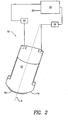
- FIG. 2 is a schematic/block diagram representing a first embodiment in accordance with the present invention in which dynamic servo control is provided of the distance between the tool and the work piece surface in relationship to the force therebetween;
- FIG. 3 is a functional block diagram representing the structure and operation control of the servo control subsystem 32 of FIG. 2 ;
- FIG. 4 is a schematic/block diagram representing a variation of the first embodiment in accordance with the present invention which achieves high speed operation
- FIG. 5 is a flow chart illustrating the process performed in accordance with a second embodiment in accordance with the present invention.
- FIG. 6 is a schematic diagram illustrating a third embodiment in accordance with the present invention.
- FIG. 7 is a block diagram illustrates how spacing control is achieved in accordance with the present embodiment.
- FIG. 2 is a schematic/block diagram illustrating a first embodiment in accordance with the present invention. Specifically, there is disclosed a tool 10 as in FIG. 1 in combination with a control subsystem 32, which controls the spacing between tool 10 and the surface of a work piece in relationship to the force between them.
- the work piece may be a silicon-on-insulator (SOI) structure, such as silicon-on-glass (SOG).
- SOI silicon-on-insulator
- SOG silicon-on-insulator
- SiC silicon carbide
- Ge germanium
- GaAs gallium arsenide
- GaP GaP
- InP InP
- other insulator materials may be employed for practicing the invention, including, but not limited to, various well known silicones and ceramics. Methods and apparatus in accordance with the invention may also find substantially broader application to industry, for example to ultra-precise lens polishing and other surface machining technologies.
- the tool is constructed to have a precisely controlled pressure inside the bonnet 14.
- a portion of the pad 16 is flattened against the surface and, upon rotation, will interact abrasively with the work piece surface to remove material.
- This flattened portion has been referred to herein, as the "spot size," and material removal will vary as the square of the spot size (i.e., its area).
- the spot size changes during rotation of the tool, for example, owing to radial error motion, the effective spot size during rotation of the tool is increased, resulting in more material removal than expected. It will also result in the force between the tool and work piece being greater than expected.
- the Z-axis control of positioning mechanism 19 of tool 10 moves the body 12 along the axis A in FIG. 2 .
- the tool 10 is positioned relative to the surface of the work piece, so that the force between them, as sensed by sensor 18, is that force necessary to produce the desired spot size.
- This "reference force” is stored in the form of a reference force signal 34, and it is applied as an input to control subsystem 32.
- sensor 18 senses the force between body 12 and the surface of the work piece and produces a signal representing that force, which is applied as a second input to control subsystem 32.
- Control subsystem 32 then produces a control signal which operates the Z-axis control of positioning mechanism 19 to adjust the distance between body 12 and the surface of the work piece so as to compensate for force variations sensed by sensor 18.
- the sensor 18 may be a load cell which is mounted inside tool 10. However, a load cell requires relative motion in order to provide a measurement of force has a somewhat limited sensitivity.
- a piezoelectric stack force sensor which is highly rigid and requires orders of magnitude less displacement than a typical load cell in order to produce a signal, may be used in place of sensor 18, in order to gain an improvement in sensitivity.
- FIG. 3 is a functional block diagram representing the structure and operation of control subsystem 32.
- Subsystem 32 itself, is modeled herein as an operational amplifier 24 and a bandwidth filter 22. This has been done for convenience of explanation, and those skilled in the art will understand that this type of servo control system is typically much more complex.
- the output signal of force sensor 18 and the force reference signal 34 are applied differentially to amplifier 24.
- the output signal of amplifier 24 passes through the bandwidth filter 22 and is then applied to the Z-axis control of positioning mechanism 19.
- control subsystem 32 is similar to that of an operational amplifier, in the sense that it produces an output signal that will cause the Z-axis motion to make the force sensor 18 signal equal the reference signal 34.
- the Z-axis motion changes the distance between body 12 and the surface of the work piece so as to cancel the change in spot size.
- Control subsystem 32 compensates for many and possibly all variations in spot size.
- the sources of such variations include bonnet radial error motion, bonnet geometry creep, thickness and flatness variations in the work piece, and machine orthogonality and axis straightness errors.
- Filter 22 represents the design bandwidth of control subsystem 32, and its bandwidth will depend upon the application and the particular machine used.
- the bonnet rotational speed is typically around 200 rpm (3.3 Hz).
- the bandwidth of filter 32 would need to be in excess of 33 Hz. If the bonnet 14 were rotated at its maximum speed of 2,000 rpm, compensation for all ripple error motions would require a bandwidth in excess of 330 Hz. This may not be achievable with a typical positioning mechanism that has a high mass in the Z-axis direction.
- a second modification is made to the first embodiment.
- the modification is made to tool 10 of FIG. 2 to produce a tool 10'.
- the modification comprises mounting a linear actuator 30 on body 12 in order to achieve small axial movements thereof.
- the actuator 30 is of very low mass in order to achieve the positioning bandwidth required for high speed rotation.
- actuator 30 is a piezoelectric actuator stack mounted on a spindle 13 for body 12.
- flexible mounts 20, 20 which are compliant in only the axial direction, an extremely low mass construction is obtained.
- a voice coil or a linear motor could be used in place of the piezoelectric crystal stack.
- FIG. 5 is a flow chart illustrating the process of a second embodiment in accordance with the present invention.
- tool 10 or 10' is operated to compensate for spot size variations without using a servo control system.
- Periodically (e.g., daily) positioning mechanism 19 is subjected to a learning operation. This involves an initial step of setting tool 10 to a reference rotational orientation and setting the force between tool 10 and the work piece so as to create the desired spot size. This step is depicted in block 50.
- the angular orientation of body 12 is then incremented by rotating the body about axis A by a predetermined amount (block 52).
- the tool to work piece spacing is then adjusted to remove any change that may have occurred in the force sense by sensor 18 (block 54) and the change in spacing is stored (block 56).
- FIG. 6 is a schematic diagram illustrating a third embodiment in accordance with the present invention.
- the work piece W is supported on a table T with the tool 10' positioned over the surface S of the work piece W.
- tool 10 would be scanned with respect to the surface S. This could be achieved by translating the tool 10 making use of its positioning system 19 (see FIG. 19) and/or translating the table T.
- Below the table T there are provided a plurality of distance sensor/actuator pairs P each including a sensor 60 and a linear actuator 62. In this embodiment, there are three such pairs P, and they are in a triangular arrangement.
- the tool 10 is used to orthogonalize the table in the usual manner.
- the tool 10 is positioned over the surface S, for example, over the left most pair P, and using its positioning mechanism 19 the distance between tool 10 and surface S is adjusted until sensor 18 senses a predefined force. Thereafter, tool 10 may be positioned over each of the pairs P in turn and the respective actuator 62 is operated to raise or lower the table T until sensor 18 once again measures the desired force.
- table T is orthogonalized. That is, the operating plane of tool 10 is parallel to the plane of table T.
- the work piece W is placed upon the table, tool 10 is positioned over one of the pairs P, and the distance between tool 10 and surface S is adjusted until sensor 18 reads a force corresponding to the desired spot size. Polishing may then begin.
- the force measured by sensor 18 is monitored constantly and the distance between surface S and tool 10 is adjusted to compensate for changes in this force.
- the actuators 62 of pairs P are operated to achieve the space adjustment.
- FIG. 7 illustrates how spacing control is achieved in accordance with the present embodiment.
- a signal corresponding to that force is saved as a reference force 34, as in FIG. 2 .
- Sensor 18 measures the force between tool 10 and surface S as the tool progresses over the surface S, and all actuators 62 are adjusted simultaneously to change the spacing between tool 10 and surface S so as to compensate for any change in force, as was the case in FIG. 2 .
- the orthogonality of table T will be maintained.
- this embodiment not only is there compensation for spot size variations due to tool 10, but also for spot size variations due to orthogonality errors of table T.
- Control subsystem 32 is substantially identical to the correspondingly numbered subsystem in FIG. 2 , and actuators 62 may be load cells, piezoelectric crystal stack actuators, voice coils, linear motors, and the like.
- the sensors 60 are linear transducers, for example, a capacitance gage. They are provided to insure that each actuator moves table T by precisely the same amount.
Abstract
Description
- The present invention relates generally to machine control and, more particularly, concerns a method and a system for precision machining or finishing of article surfaces. It finds application, among other uses, in polishing of the semiconductor layer of semiconductor-on-insulator structures.
- The present invention will be disclosed in terms of a particular application. However, other applications are disclosed and further applications will be apparent to those skilled in the art. Particular applications were disclosed for convenience of description and without the intention of limiting the invention to any of them.
- To date, the semiconductor material most commonly used in semiconductor-on-insulator structures has been silicon, and glass is a common insulator. Silicon-on-insulator technology is becoming increasingly important for high performance thin film transistors, solar cells, and display, such as active matrix displays. Silicon-on-insulator wafers consist of a thin layer of substantially single crystal silicon (generally 0.1-0.3 microns in thickness but, in some cases, as thick as 5 microns) on an insulating material.
- Once the semiconductor-on-insulator structure has been bonded to a thin film of silicon, it is typically necessary to polish the surface of the silicon layer to produce a layer having a substantially uniform thickness, in order to facilitate the formation of thin film transistor (TFT) circuitry on the silicon.
- As a specific example, silicon-on-glass (SiOG) substrates are subjected to a machining process that thins the surface film. This is commonly performed by "deterministic polishing," an abrading process performed by a tool that has a substantially smaller polishing contact zone than the component being machined. This type of process is typically performed today by the use of ultra-precise optical lens polishing machines, a well-known source of which is Zeeko Limited of Coalville, Leicestershire, UK. A machine of this type is disclosed in
U.S. Patent No. 6,796,877 , entitled ABRADING MACHINE and issued to Bingham et al. On September 28, 2004. As is typical, precision movement between a machine tool and work piece is provided in three Cartesian coordinates, in order to achieve machining of the entire surface. - The machining tool of the type disclosed in
U.S. Patent No. 6,796,877 may be referred to herein as a bonnet/pad machine, and is illustrated schematically inFIG. 1 . Thetool 10 has a generallycylindrical body 12 and a working head orbonnet 14 which is internally pressurized to a predetermined pressure. For example, the bonnet may be a partially spherical or bulbous, fiber reinforced rubber diaphragm. Apolishing pad 16 is bonded onto the surface ofbonnet 14. In operation, thepad 16 is applied to a surface of the component being machined and is rotated about an axis of rotation A, in order to abrade the surface. - Prior to use, the tool must be calibrated to the work piece surface to be machined. In order to do this, the
pad 16 is touched to the surface at a number of points in a predetermined pattern.Tool 10 is provided with apositioning mechanism 19 providing precision movement along three axes and the axial movement corresponds to the Z-axis control. In performing the calibration, when thepad 16 is touched to one of the calibration points on the surface,bonnet 14 is moved axially until a predetermined force is sensed by asensor 18 provided intool 10. This assures consistency of contact. After a set of calibration points has been taken, tool movement can be controlled to assure that the bonnet will remain in a plane or other appropriate contour corresponding to the intended finished shape of the surface to be machined. In addition, an appropriate axial spacing ofbonnet 14 relative to the surface to be polished will be maintained. This is normally an interference spacing that would place the front of the bonnet past the surface of the work piece, causing compression of the bonnet against the surface. The actual machining process is then performed by rotatingbonnet 14 and simultaneously moving it in a predetermined scanning pattern along a contour (e.g., a plane) relative to the work piece surface to be machined. Although different scanning patterns are available, the most common pattern is a series of closely spaced parallel lines or a "raster", similar to the line pattern scanned on a cathode ray tube of a traditional television set. - The requirements for SiOG film thinning are quite stringent. It would be desirable for the final film thickness to be controlled with an accuracy of about ± 8 nm. It is known that material removal is approximately linearly proportional to the scan rate of the bonnet and the bonnet rotational speed. However, it is proportional to the square of the polishing spot size, or the area of the pad which actually performs the abrasion. Polishing spot size is controlled by the amount of force between the bonnet and the surface being machined, which results from its interference contact with the surface to be polished. All of these parameters are well understood, and current polishing practice closely controls them.
- It has been found that deviations in the rotation of
bonnet 14 have a profound effect on material removal. Such deviations could be measured by rotatingbonnet 14 and measuring the amount of radial (eccentric) movement, which will be referred to herein as "radial error motion." It will be appreciated that any eccentricity in pad rotation will make the spot size effectively larger, resulting more material removal than expected, at high rotational speeds and time variable material removal at low rotational speeds. It has been found that a radial error motion of approximately 50 microns may result in a film thickness variability of approximately 15 nm, larger than the total film thickness tolerance. Every effort is made to minimize the combined radial error motion of the bonnet and pad (e.g., by diamond turning and/or cup grinding in situ). However, this radial error motion can rarely be reduced below 30 microns. - It is therefore clear that, in order to achieve the required film thickness control when performing the deterministic polishing with a bonnet/pad type machine, the bonnet spot size must be controlled to tighter tolerances than can be achieved by bonnet truing.
- In accordance with the present invention as defined in
method claim 1 and apparatus claim 5, the relative spacing between a bonnet/pad type tool and the surface of the work piece is controlled dynamically so that the area of the abrasive pad in contact with the surface of the work piece (also referred to herein as "spot size") remains constant, thereby eliminating spot size variations and the accompanying variations in material removal, which produce surface height fluctuations. Spot size variation results from various sources including radial error motion of the pad. For a given internal pressure of the tool, the spot size will vary in relationship to the actual axial position between the tool and the work piece surface. In accordance with a first embodiment of the invention, the force between the tool and the surface of the work piece is sensed and the axial spacing between the tool and the surface of the work piece is controlled in reverse sense to the force variation, in order to compensate for changes in spot size. In accordance with this first embodiment, dynamic real time control is exercised, for example, by using a server control subsystem. - In accordance with a second embodiment, the variation of a parameter which affects spot size is measured prior to use. For example, radial error motion of the pad as it rotates may be measured and stored. Using the stored information, during operation, a time varying adjustment in the distance between the tool and the surface of the work piece is then made, as the pad rotates. That distance adjustment compensates for radial error motion, producing a uniform spot size.
- In general, the distance between the tool and work piece surface is controlled by axial movement of the tool. However, in accordance with a third embodiment, the work table supporting the work piece is itself has at least one, and optionally a plurality of actuator/position-sensor pairs spaced in a two dimensional pattern under the table. The actuators are controlled to adjust table elevation to change the distance between the tool and work piece so as to compensate for spot size variation. This permits not only control of the spacing between the tool and the work piece surface, but also the tilt of the work piece surface in three dimensions to control orthogonality.
- The foregoing brief description and further objects, features, and advantages of the present invention will be understood more completely from the ensuing detailed description of specific embodiments in accordance with the present invention, with reference being had to the accompanying drawings, in which:
-
FIG. 1 is a schematic diagram illustrating a bonnet/pad type abrasive polishing tool; -
FIG. 2 is a schematic/block diagram representing a first embodiment in accordance with the present invention in which dynamic servo control is provided of the distance between the tool and the work piece surface in relationship to the force therebetween; -
FIG. 3 is a functional block diagram representing the structure and operation control of theservo control subsystem 32 ofFIG. 2 ; -
FIG. 4 is a schematic/block diagram representing a variation of the first embodiment in accordance with the present invention which achieves high speed operation -
FIG. 5 is a flow chart illustrating the process performed in accordance with a second embodiment in accordance with the present invention; -
FIG. 6 is a schematic diagram illustrating a third embodiment in accordance with the present invention; and -
FIG. 7 is a block diagram illustrates how spacing control is achieved in accordance with the present embodiment. -
FIG. 2 is a schematic/block diagram illustrating a first embodiment in accordance with the present invention. Specifically, there is disclosed atool 10 as inFIG. 1 in combination with acontrol subsystem 32, which controls the spacing betweentool 10 and the surface of a work piece in relationship to the force between them. - The work piece may be a silicon-on-insulator (SOI) structure, such as silicon-on-glass (SOG). As used herein, "silicon-on-insulator" or "silicon-on-glass" shall be construed more broadly as including semiconductor materials other than silicon or those including silicon, and it will be understood to embrace insulator materials other than glass. For example, other useful semiconductor materials for practicing the invention include, but are not limited to, silicon germanium (SiGe), silicon carbide (SiC), germanium (Ge), gallium arsenide (GaAs), GaP, and InP. Also for example, other insulator materials may be employed for practicing the invention, including, but not limited to, various well known silicones and ceramics. Methods and apparatus in accordance with the invention may also find substantially broader application to industry, for example to ultra-precise lens polishing and other surface machining technologies.
- Some discussion is in order about the source of spot size variation which results in height fluctuations of the finished surface of the work piece when using a bonnet/
pad type tool 10. The tool is constructed to have a precisely controlled pressure inside thebonnet 14. When thebonnet 14 is pressed against the surface of the work piece, a portion of thepad 16 is flattened against the surface and, upon rotation, will interact abrasively with the work piece surface to remove material. This flattened portion has been referred to herein, as the "spot size," and material removal will vary as the square of the spot size (i.e., its area). Inasmuch as thebonnet 14 has a precisely controlled internal pressure, the force between thebonnet 14 and work piece will be equal to the product of the spot size (area) and the internal pressure. If the spot size changes during rotation of the tool, for example, owing to radial error motion, the effective spot size during rotation of the tool is increased, resulting in more material removal than expected. It will also result in the force between the tool and work piece being greater than expected. - For the present embodiment, the Z-axis control of
positioning mechanism 19 oftool 10 moves thebody 12 along the axis A inFIG. 2 . Initially, thetool 10 is positioned relative to the surface of the work piece, so that the force between them, as sensed bysensor 18, is that force necessary to produce the desired spot size. This "reference force" is stored in the form of areference force signal 34, and it is applied as an input to controlsubsystem 32. During operation,sensor 18 senses the force betweenbody 12 and the surface of the work piece and produces a signal representing that force, which is applied as a second input to controlsubsystem 32.Control subsystem 32 then produces a control signal which operates the Z-axis control ofpositioning mechanism 19 to adjust the distance betweenbody 12 and the surface of the work piece so as to compensate for force variations sensed bysensor 18. - The
sensor 18 may be a load cell which is mounted insidetool 10. However, a load cell requires relative motion in order to provide a measurement of force has a somewhat limited sensitivity. In accordance with one variation of the first embodiment, a piezoelectric stack force sensor, which is highly rigid and requires orders of magnitude less displacement than a typical load cell in order to produce a signal, may be used in place ofsensor 18, in order to gain an improvement in sensitivity. -
FIG. 3 is a functional block diagram representing the structure and operation ofcontrol subsystem 32.Subsystem 32, itself, is modeled herein as anoperational amplifier 24 and abandwidth filter 22. This has been done for convenience of explanation, and those skilled in the art will understand that this type of servo control system is typically much more complex. The output signal offorce sensor 18 and theforce reference signal 34 are applied differentially toamplifier 24. The output signal ofamplifier 24 passes through thebandwidth filter 22 and is then applied to the Z-axis control ofpositioning mechanism 19. - In operation, the Z-axis control of the machine is operated in the usual manner to place the
bonnet 14 into contact with the surface of the work piece so that a predetermined force is attained. That force will be the force necessary to achieve the intended spot size. At that point, the value of the signal produced by theforce sensor 18 is saved asreference signal 34.
The operation ofcontrol subsystem 32 is similar to that of an operational amplifier, in the sense that it produces an output signal that will cause the Z-axis motion to make theforce sensor 18 signal equal thereference signal 34. In other words, as the spot size deviates from the intended value, the Z-axis motion changes the distance betweenbody 12 and the surface of the work piece so as to cancel the change in spot size. Thus, there is a dynamic, time varying adjustment of the distance betweenbody 12 and the surface of the work piece. -
Control subsystem 32 compensates for many and possibly all variations in spot size. The sources of such variations include bonnet radial error motion, bonnet geometry creep, thickness and flatness variations in the work piece, and machine orthogonality and axis straightness errors. -
Filter 22 represents the design bandwidth ofcontrol subsystem 32, and its bandwidth will depend upon the application and the particular machine used. For a bonnet/pad machine used to polish the surface layer on an SiOG substrate, the bonnet rotational speed is typically around 200 rpm (3.3 Hz). However, there can typically be 10 ripple error motions superimposed upon each revolution of thebonnet 14. In order to correct for all of these, the bandwidth offilter 32 would need to be in excess of 33 Hz. If thebonnet 14 were rotated at its maximum speed of 2,000 rpm, compensation for all ripple error motions would require a bandwidth in excess of 330 Hz. This may not be achievable with a typical positioning mechanism that has a high mass in the Z-axis direction. - In order to achieve operation with high speed rotation, a second modification is made to the first embodiment. With reference to
FIG. 4 , the modification is made totool 10 ofFIG. 2 to produce a tool 10'. The modification comprises mounting alinear actuator 30 onbody 12 in order to achieve small axial movements thereof. Theactuator 30 is of very low mass in order to achieve the positioning bandwidth required for high speed rotation. In this case,actuator 30 is a piezoelectric actuator stack mounted on aspindle 13 forbody 12. By providingflexible mounts FIGS. 2 and3 . -
FIG. 5 is a flow chart illustrating the process of a second embodiment in accordance with the present invention. In this case,tool 10 or 10' is operated to compensate for spot size variations without using a servo control system. Periodically (e.g., daily)positioning mechanism 19 is subjected to a learning operation. This involves an initial step of settingtool 10 to a reference rotational orientation and setting the force betweentool 10 and the work piece so as to create the desired spot size. This step is depicted inblock 50. The angular orientation ofbody 12 is then incremented by rotating the body about axis A by a predetermined amount (block 52). The tool to work piece spacing is then adjusted to remove any change that may have occurred in the force sense by sensor 18 (block 54) and the change in spacing is stored (block 56). By virtue of a test performed atblock 58, the steps in block 52-56 are repeated untilbody 12 has completed a comlete 360° rotation about axis A and returned to its reference orientation. Polishing of the work piece is then begun and the sequence of spacing changes is played back from memory in synchronism with the time varying rotational position of bonnet 14 (block 60). In this manner, spot size variations are compensated during each rotation of the bonnet. Once the control processor for thepositioning mechanism 19 is trained, each time a new work piece is to be polished, it is only necessary to adjustpositioning mechanism 19 so that the force betweentool 10 and the work piece is at the nominal value whilebonnet 14 is in the reference position. Polishing may then commence, and the stored force sequence will be played back to compensate for spot size variations. -
FIG. 6 is a schematic diagram illustrating a third embodiment in accordance with the present invention. In this case, the work piece W is supported on a table T with the tool 10' positioned over the surface S of the work piece W. In operation,tool 10 would be scanned with respect to the surface S. This could be achieved by translating thetool 10 making use of its positioning system 19 (see FIG. 19) and/or translating the table T. Below the table T, there are provided a plurality of distance sensor/actuator pairs P each including asensor 60 and alinear actuator 62. In this embodiment, there are three such pairs P, and they are in a triangular arrangement. Thetool 10 is used to orthogonalize the table in the usual manner. That is, with table T empty, thetool 10 is positioned over the surface S, for example, over the left most pair P, and using itspositioning mechanism 19 the distance betweentool 10 and surface S is adjusted untilsensor 18 senses a predefined force. Thereafter,tool 10 may be positioned over each of the pairs P in turn and therespective actuator 62 is operated to raise or lower the table T untilsensor 18 once again measures the desired force. At the conclusion of this operation, table T is orthogonalized. That is, the operating plane oftool 10 is parallel to the plane of table T. Thereafter, the work piece W is placed upon the table,tool 10 is positioned over one of the pairs P, and the distance betweentool 10 and surface S is adjusted untilsensor 18 reads a force corresponding to the desired spot size. Polishing may then begin. - As was the case with the first embodiment (
FIG. 2 ), the force measured bysensor 18 is monitored constantly and the distance between surface S andtool 10 is adjusted to compensate for changes in this force. However, in this case, theactuators 62 of pairs P are operated to achieve the space adjustment. - The schematic diagram of
FIG. 7 illustrates how spacing control is achieved in accordance with the present embodiment. When the force is originally set to achieve the desired spot size, a signal corresponding to that force is saved as areference force 34, as inFIG. 2 .Sensor 18 measures the force betweentool 10 and surface S as the tool progresses over the surface S, and allactuators 62 are adjusted simultaneously to change the spacing betweentool 10 and surface S so as to compensate for any change in force, as was the case inFIG. 2 . However, since all of the actuators operate simultaneously, the orthogonality of table T will be maintained. Thus, in this embodiment, not only is there compensation for spot size variations due totool 10, but also for spot size variations due to orthogonality errors of table T. -
Control subsystem 32 is substantially identical to the correspondingly numbered subsystem inFIG. 2 , andactuators 62 may be load cells, piezoelectric crystal stack actuators, voice coils, linear motors, and the like. Thesensors 60 are linear transducers, for example, a capacitance gage. They are provided to insure that each actuator moves table T by precisely the same amount. - Although specific embodiments of the invention have been disclosed for illustrative purposes, those skilled in the art will appreciate that many additions, modification, and substitutions are possible within the scope of the invention as defined by the accompanying claims.
Claims (10)
- In a machine tool including a pressurized chamber behind a yieldable, bulbous carrier (14) for an abrasive layer (16) which is moved against a surface (S) of a work piece (W) to be machined, the abrasive layer being forced against the surface so that a spot of the layer is retained in abrasive contact with the surface, a method for compensating for variations in the size of the spot during use of the tool (10), characterised by the steps of:urging the tool against the surface with an applied force calculated to produce a spot of a predetermined size;during operation of the tool, comparing the actual force between the tool and the surface with the applied force; andadjusting the distance between the tool and the surface to compensate for any difference between the actual force and the applied force, making the two forces substantially equal.
- The method of claim 1, wherein the adjusting step is performed by a servomechanism which is jointly responsive to signals representing the applied force and the actual force, to produce a driving signal for an actuator (30) which causes the actuator to change the distance between the tool and the surface so as to compensate for any difference between the actual force and the applied force.
- The method of claim 2 wherein the work piece is supported on a table (T), the tool and table being relatively moveable, the actuator acting on the table to move it toward and away from the tool.
- The method of claim 1 wherein the comparing and adjusting steps are performed during a preliminary learning operation of the tool during which actual operation is simulated, a correction signal representing a sequence of distance adjustments being stored, the correction signal being applied as a driving signal for an actuator during actual operation and causing the actuator to change the distance between the tool and the surface so as to compensate for any differences between the actual force and the applied force.
- A machine tool including a pressurized chamber behind a yieldable, bulbous carrier (14) for an abrasive layer (16) which is moved against a surface (S) of a work piece (W) to be machined, the abrasive layer being forced against the surface so that a spot of the layer is retained in abrasive contact with the surface, characterised in that, for compensating for variations in the size of the spot during use of the tool (10), the machine tool comprises:an actuator (30) initially urging the tool against the surface with an applied force calculated to produce a spot of a predetermined size;a force sensor (18) for sensing the actual force between the tool and the surface;a comparator acting during operation of the tool to compare the actual force between the tool and the surface with the applied force to produce a difference signal representing the same; anda driver responsive to the difference signal and acting on the actuator to adjust distance between the tool and the surface to compensate for any difference between the actual force and the applied force, making the two forces substantially equal.
- The machine tool of claim 5, wherein the comparator and driver are part of a servomechanism which is jointly responsive to signals representing the applied force and the actual force, to produce a driving signal for the actuator which causes the actuator to change the distance between the tool and the surface so as to compensate for any difference between the actual force and the applied force.
- The machine tool of claim 6 wherein the work piece is supported on a table (T), the tool and table being relatively moveable, the actuator acting on the table to move it toward and away from the tool.
- The machine tool of claim 7 further comprising a plurality of additional actuators, the actuators being arranged in a two-dimensional pattern, the actuators being operated so as to move the table without changing its attitude to the tool.
- The machine tool of claim 5 wherein the comparator and drivers are operated during a preliminary learning operation of the tool during which actual operation is simulated, a correction signal representing a sequence of distance adjustments being stored, the correction signal being provided to the driver and applied as a driving signal for the actuator during actual operation and causing the actuator to change the distance between the tool and the surface so as to compensate for any differences between the actual force and the applied force.
- The machine tool of claim 9 wherein the tool rotates about an axis during operation, the tool being rotated during the learning operation in a series of angular increments from a reference orientation, the comparator producing a series of distance adjustment signals after each increment which are stored as a correction signal, the correction signal being applied to the tool synchronously during a rotation during actual operation.
Applications Claiming Priority (2)
| Application Number | Priority Date | Filing Date | Title |
|---|---|---|---|
| US87200906P | 2006-11-30 | 2006-11-30 | |
| PCT/US2007/024417 WO2008066801A1 (en) | 2006-11-30 | 2007-11-26 | Precision abrasive machining of work piece surfaces |
Publications (2)
| Publication Number | Publication Date |
|---|---|
| EP2094440A1 EP2094440A1 (en) | 2009-09-02 |
| EP2094440B1 true EP2094440B1 (en) | 2010-04-21 |
Family
ID=39291898
Family Applications (1)
| Application Number | Title | Priority Date | Filing Date |
|---|---|---|---|
| EP07862251A Expired - Fee Related EP2094440B1 (en) | 2006-11-30 | 2007-11-26 | Precision abrasive machining of work piece surfaces |
Country Status (7)
| Country | Link |
|---|---|
| US (1) | US7831327B2 (en) |
| EP (1) | EP2094440B1 (en) |
| JP (1) | JP5469461B2 (en) |
| KR (1) | KR20090087943A (en) |
| CN (1) | CN101541475B (en) |
| DE (1) | DE602007006051D1 (en) |
| WO (1) | WO2008066801A1 (en) |
Families Citing this family (6)
| Publication number | Priority date | Publication date | Assignee | Title |
|---|---|---|---|---|
| CN102825543B (en) * | 2012-09-18 | 2014-09-03 | 厦门大学 | Air bag polishing head for air bag polishing |
| CN103056772A (en) * | 2012-12-25 | 2013-04-24 | 北京工业大学 | Compensation method of grinder rigidity based on negative flexibility principle |
| CN104625960B (en) * | 2015-02-06 | 2017-09-19 | 苏州富强科技有限公司 | Polishing machine with drive component |
| CN106239312B (en) * | 2016-08-02 | 2018-04-10 | 中国科学院长春光学精密机械与物理研究所 | A kind of grinding head connecting device based on parallel-crank mechanism |
| CN108161646A (en) * | 2018-01-11 | 2018-06-15 | 沈阳仪表科学研究院有限公司 | The intelligent flexible polishing method of aspherical optical element and its used intelligent flexible burnishing device |
| CN109062013B (en) * | 2018-09-06 | 2023-06-06 | 重庆科技学院 | Small workpiece fixture of photoetching machine |
Family Cites Families (19)
| Publication number | Priority date | Publication date | Assignee | Title |
|---|---|---|---|---|
| US4679271A (en) * | 1986-03-14 | 1987-07-14 | Tennant Company | Automatic tool force compensator for a surface maintenance machine |
| JPH04244373A (en) * | 1991-01-30 | 1992-09-01 | Hitachi Ltd | Polishing method and device |
| JP3304994B2 (en) * | 1991-08-30 | 2002-07-22 | キヤノン株式会社 | Polishing method and polishing apparatus |
| GB9512262D0 (en) * | 1995-06-16 | 1995-08-16 | Bingham Richard G | Tool for computer-controlled machine for optical polishing and figuring |
| DE19635831A1 (en) * | 1996-09-04 | 1998-03-05 | Hell Ag Linotype | Method and device for controlling an engraving device |
| US6183354B1 (en) * | 1996-11-08 | 2001-02-06 | Applied Materials, Inc. | Carrier head with a flexible membrane for a chemical mechanical polishing system |
| US5951370A (en) * | 1997-10-02 | 1999-09-14 | Speedfam-Ipec Corp. | Method and apparatus for monitoring and controlling the flatness of a polishing pad |
| US5980368A (en) * | 1997-11-05 | 1999-11-09 | Aplex Group | Polishing tool having a sealed fluid chamber for support of polishing pad |
| US6165057A (en) * | 1998-05-15 | 2000-12-26 | Gill, Jr.; Gerald L. | Apparatus for localized planarization of semiconductor wafer surface |
| WO2000032353A2 (en) * | 1998-12-01 | 2000-06-08 | Optical Generics Limited | A polishing machine and method |
| US6517414B1 (en) * | 2000-03-10 | 2003-02-11 | Appied Materials, Inc. | Method and apparatus for controlling a pad conditioning process of a chemical-mechanical polishing apparatus |
| JP2001260020A (en) * | 2000-03-16 | 2001-09-25 | Canon Inc | Pressurizing force variable polishing device |
| US6558232B1 (en) * | 2000-05-12 | 2003-05-06 | Multi-Planar Technologies, Inc. | System and method for CMP having multi-pressure zone loading for improved edge and annular zone material removal control |
| US6506105B1 (en) * | 2000-05-12 | 2003-01-14 | Multi-Planar Technologies, Inc. | System and method for pneumatic diaphragm CMP head having separate retaining ring and multi-region wafer pressure control |
| US6569771B2 (en) * | 2001-10-31 | 2003-05-27 | United Microelectronics Corp. | Carrier head for chemical mechanical polishing |
| US7574947B2 (en) * | 2002-05-29 | 2009-08-18 | Massachusetts Institute Of Technology | Rotary fast tool servo system and methods |
| US7176528B2 (en) * | 2003-02-18 | 2007-02-13 | Corning Incorporated | Glass-based SOI structures |
| US7312154B2 (en) * | 2005-12-20 | 2007-12-25 | Corning Incorporated | Method of polishing a semiconductor-on-insulator structure |
| US20070246450A1 (en) * | 2006-04-21 | 2007-10-25 | Cady Raymond C | High temperature anodic bonding apparatus |
-
2007
- 2007-11-26 DE DE602007006051T patent/DE602007006051D1/en active Active
- 2007-11-26 EP EP07862251A patent/EP2094440B1/en not_active Expired - Fee Related
- 2007-11-26 CN CN2007800443915A patent/CN101541475B/en not_active Expired - Fee Related
- 2007-11-26 JP JP2009539284A patent/JP5469461B2/en not_active Expired - Fee Related
- 2007-11-26 WO PCT/US2007/024417 patent/WO2008066801A1/en active Application Filing
- 2007-11-26 KR KR1020097013725A patent/KR20090087943A/en not_active Application Discontinuation
- 2007-11-30 US US11/998,691 patent/US7831327B2/en not_active Expired - Fee Related
Also Published As
| Publication number | Publication date |
|---|---|
| JP2010511520A (en) | 2010-04-15 |
| JP5469461B2 (en) | 2014-04-16 |
| CN101541475B (en) | 2011-03-16 |
| US20080132148A1 (en) | 2008-06-05 |
| US7831327B2 (en) | 2010-11-09 |
| CN101541475A (en) | 2009-09-23 |
| KR20090087943A (en) | 2009-08-18 |
| WO2008066801A1 (en) | 2008-06-05 |
| DE602007006051D1 (en) | 2010-06-02 |
| EP2094440A1 (en) | 2009-09-02 |
Similar Documents
| Publication | Publication Date | Title |
|---|---|---|
| EP2094440B1 (en) | Precision abrasive machining of work piece surfaces | |
| KR100938484B1 (en) | Precision machining apparatus and precision machining method | |
| US6077155A (en) | Polishing device and correcting method therefor | |
| US6237452B1 (en) | Precision high speed turning machine | |
| US6428389B2 (en) | Polishing apparatus | |
| JP2006513050A (en) | High precision processing of object surface, especially polishing and lapping method and apparatus for semiconductor substrate | |
| US5083401A (en) | Method of polishing | |
| JPH0929598A (en) | Processing device for aspheric surface shape object | |
| JPH01193172A (en) | Grinding/polishing method for thin film on substrate | |
| JPH09150355A (en) | Grinding machine | |
| JP2000337375A (en) | Static pressure gas bearing | |
| JP4762194B2 (en) | Processing apparatus and processing method | |
| JPH04244373A (en) | Polishing method and device | |
| JP2004160565A (en) | Polishing method and shape variable polishing tool device | |
| JPH0623663A (en) | Super smoothing non-contact polishing method and device | |
| KR100608270B1 (en) | Method of compensating waviness in Ultraprecision machining | |
| JPH0557520A (en) | Working device | |
| JP2001326203A (en) | Super-flattening device | |
| JPH1110498A (en) | Machining device having face oscillation correction mechanism which employs solid actuator | |
| JPH04305924A (en) | Production device for semiconductor substrate | |
| JPH0557521A (en) | Working device | |
| JP2003019665A (en) | Machining apparatus and machining method | |
| JPH0679582A (en) | Highly precise cutting processing method and cutting processing device | |
| Jones | Fabrication of Large Off-axis Optics | |
| JPH11221763A (en) | Grinding method and grinding device |
Legal Events
| Date | Code | Title | Description |
|---|---|---|---|
| PUAI | Public reference made under article 153(3) epc to a published international application that has entered the european phase |
Free format text: ORIGINAL CODE: 0009012 |
|
| 17P | Request for examination filed |
Effective date: 20090305 |
|
| AK | Designated contracting states |
Kind code of ref document: A1 Designated state(s): AT BE BG CH CY CZ DE DK EE ES FI FR GB GR HU IE IS IT LI LT LU LV MC MT NL PL PT RO SE SI SK TR |
|
| RIN1 | Information on inventor provided before grant (corrected) |
Inventor name: STOCKER, MARK A |
|
| GRAP | Despatch of communication of intention to grant a patent |
Free format text: ORIGINAL CODE: EPIDOSNIGR1 |
|
| RBV | Designated contracting states (corrected) |
Designated state(s): AT BE BG CH CY CZ DE DK EE ES FI FR GB GR HU IE IS IT LI LT LU LV MC MT NL PL PT RO SE SI SK TR |
|
| GRAS | Grant fee paid |
Free format text: ORIGINAL CODE: EPIDOSNIGR3 |
|
| DAX | Request for extension of the european patent (deleted) | ||
| GRAA | (expected) grant |
Free format text: ORIGINAL CODE: 0009210 |
|
| RBV | Designated contracting states (corrected) |
Designated state(s): DE FR GB |
|
| AK | Designated contracting states |
Kind code of ref document: B1 Designated state(s): DE FR GB |
|
| REG | Reference to a national code |
Ref country code: GB Ref legal event code: FG4D |
|
| REF | Corresponds to: |
Ref document number: 602007006051 Country of ref document: DE Date of ref document: 20100602 Kind code of ref document: P |
|
| RIN2 | Information on inventor provided after grant (corrected) |
Inventor name: STOCKER, MARK ANDREW |
|
| PLBE | No opposition filed within time limit |
Free format text: ORIGINAL CODE: 0009261 |
|
| STAA | Information on the status of an ep patent application or granted ep patent |
Free format text: STATUS: NO OPPOSITION FILED WITHIN TIME LIMIT |
|
| 26N | No opposition filed |
Effective date: 20110124 |
|
| REG | Reference to a national code |
Ref country code: DE Ref legal event code: R119 Ref document number: 602007006051 Country of ref document: DE Effective date: 20110601 Ref country code: DE Ref legal event code: R119 Ref document number: 602007006051 Country of ref document: DE Effective date: 20110531 |
|
| GBPC | Gb: european patent ceased through non-payment of renewal fee |
Effective date: 20111126 |
|
| PG25 | Lapsed in a contracting state [announced via postgrant information from national office to epo] |
Ref country code: GB Free format text: LAPSE BECAUSE OF NON-PAYMENT OF DUE FEES Effective date: 20111126 |
|
| PG25 | Lapsed in a contracting state [announced via postgrant information from national office to epo] |
Ref country code: DE Free format text: LAPSE BECAUSE OF NON-PAYMENT OF DUE FEES Effective date: 20110531 |
|
| REG | Reference to a national code |
Ref country code: FR Ref legal event code: PLFP Year of fee payment: 9 |
|
| PGFP | Annual fee paid to national office [announced via postgrant information from national office to epo] |
Ref country code: FR Payment date: 20151117 Year of fee payment: 9 |
|
| REG | Reference to a national code |
Ref country code: FR Ref legal event code: ST Effective date: 20170731 |
|
| PG25 | Lapsed in a contracting state [announced via postgrant information from national office to epo] |
Ref country code: FR Free format text: LAPSE BECAUSE OF NON-PAYMENT OF DUE FEES Effective date: 20161130 |