EP2093811A2 - Gehäusestruktur eines Verbundhalbleiterbauelements und zugehöriges Herstellungsverfahren - Google Patents
Gehäusestruktur eines Verbundhalbleiterbauelements und zugehöriges Herstellungsverfahren Download PDFInfo
- Publication number
- EP2093811A2 EP2093811A2 EP09153073A EP09153073A EP2093811A2 EP 2093811 A2 EP2093811 A2 EP 2093811A2 EP 09153073 A EP09153073 A EP 09153073A EP 09153073 A EP09153073 A EP 09153073A EP 2093811 A2 EP2093811 A2 EP 2093811A2
- Authority
- EP
- European Patent Office
- Prior art keywords
- die
- conductive film
- bonding
- semiconductor device
- compound semiconductor
- Prior art date
- Legal status (The legal status is an assumption and is not a legal conclusion. Google has not performed a legal analysis and makes no representation as to the accuracy of the status listed.)
- Granted
Links
- 239000004065 semiconductor Substances 0.000 title claims abstract description 47
- 150000001875 compounds Chemical class 0.000 title claims abstract description 44
- 238000000034 method Methods 0.000 title claims description 34
- 239000010408 film Substances 0.000 claims abstract description 82
- 239000000758 substrate Substances 0.000 claims abstract description 52
- 239000010409 thin film Substances 0.000 claims abstract description 43
- 239000002184 metal Substances 0.000 claims abstract description 33
- 229910052751 metal Inorganic materials 0.000 claims abstract description 33
- 239000000463 material Substances 0.000 claims abstract description 20
- 238000005538 encapsulation Methods 0.000 claims abstract description 18
- 239000003989 dielectric material Substances 0.000 claims abstract description 16
- 239000011810 insulating material Substances 0.000 claims description 15
- 238000004519 manufacturing process Methods 0.000 claims description 15
- 238000005553 drilling Methods 0.000 claims description 6
- 238000005323 electroforming Methods 0.000 claims description 6
- 239000003822 epoxy resin Substances 0.000 claims description 6
- 238000005530 etching Methods 0.000 claims description 6
- 229920000647 polyepoxide Polymers 0.000 claims description 6
- ATJFFYVFTNAWJD-UHFFFAOYSA-N Tin Chemical compound [Sn] ATJFFYVFTNAWJD-UHFFFAOYSA-N 0.000 claims description 5
- 229920001296 polysiloxane Polymers 0.000 claims description 4
- 238000000206 photolithography Methods 0.000 claims description 3
- 229920000642 polymer Polymers 0.000 claims description 3
- 238000004080 punching Methods 0.000 claims description 3
- 229910052814 silicon oxide Inorganic materials 0.000 claims description 3
- 238000010586 diagram Methods 0.000 description 13
- RYGMFSIKBFXOCR-UHFFFAOYSA-N Copper Chemical compound [Cu] RYGMFSIKBFXOCR-UHFFFAOYSA-N 0.000 description 6
- 239000011889 copper foil Substances 0.000 description 6
- 230000017525 heat dissipation Effects 0.000 description 4
- 238000009413 insulation Methods 0.000 description 4
- 238000005286 illumination Methods 0.000 description 3
- 238000000465 moulding Methods 0.000 description 3
- 230000015572 biosynthetic process Effects 0.000 description 2
- 230000000694 effects Effects 0.000 description 2
- 238000005516 engineering process Methods 0.000 description 2
- 238000002844 melting Methods 0.000 description 2
- 230000008018 melting Effects 0.000 description 2
- 229920002120 photoresistant polymer Polymers 0.000 description 2
- 239000000853 adhesive Substances 0.000 description 1
- 230000001070 adhesive effect Effects 0.000 description 1
- 238000010292 electrical insulation Methods 0.000 description 1
- 230000007613 environmental effect Effects 0.000 description 1
- 230000004907 flux Effects 0.000 description 1
- PCHJSUWPFVWCPO-UHFFFAOYSA-N gold Chemical compound [Au] PCHJSUWPFVWCPO-UHFFFAOYSA-N 0.000 description 1
- 239000010931 gold Substances 0.000 description 1
- 229910052737 gold Inorganic materials 0.000 description 1
- 239000004973 liquid crystal related substance Substances 0.000 description 1
- 229910000679 solder Inorganic materials 0.000 description 1
- 238000005476 soldering Methods 0.000 description 1
Images


Classifications
-
- H—ELECTRICITY
- H01—ELECTRIC ELEMENTS
- H01L—SEMICONDUCTOR DEVICES NOT COVERED BY CLASS H10
- H01L33/00—Semiconductor devices with at least one potential-jump barrier or surface barrier specially adapted for light emission; Processes or apparatus specially adapted for the manufacture or treatment thereof or of parts thereof; Details thereof
- H01L33/48—Semiconductor devices with at least one potential-jump barrier or surface barrier specially adapted for light emission; Processes or apparatus specially adapted for the manufacture or treatment thereof or of parts thereof; Details thereof characterised by the semiconductor body packages
- H01L33/483—Containers
- H01L33/486—Containers adapted for surface mounting
-
- H—ELECTRICITY
- H01—ELECTRIC ELEMENTS
- H01L—SEMICONDUCTOR DEVICES NOT COVERED BY CLASS H10
- H01L31/00—Semiconductor devices sensitive to infrared radiation, light, electromagnetic radiation of shorter wavelength or corpuscular radiation and specially adapted either for the conversion of the energy of such radiation into electrical energy or for the control of electrical energy by such radiation; Processes or apparatus specially adapted for the manufacture or treatment thereof or of parts thereof; Details thereof
- H01L31/02—Details
- H01L31/0203—Containers; Encapsulations, e.g. encapsulation of photodiodes
-
- H—ELECTRICITY
- H01—ELECTRIC ELEMENTS
- H01L—SEMICONDUCTOR DEVICES NOT COVERED BY CLASS H10
- H01L2224/00—Indexing scheme for arrangements for connecting or disconnecting semiconductor or solid-state bodies and methods related thereto as covered by H01L24/00
- H01L2224/01—Means for bonding being attached to, or being formed on, the surface to be connected, e.g. chip-to-package, die-attach, "first-level" interconnects; Manufacturing methods related thereto
- H01L2224/02—Bonding areas; Manufacturing methods related thereto
- H01L2224/04—Structure, shape, material or disposition of the bonding areas prior to the connecting process
- H01L2224/05—Structure, shape, material or disposition of the bonding areas prior to the connecting process of an individual bonding area
- H01L2224/0554—External layer
- H01L2224/0555—Shape
- H01L2224/05552—Shape in top view
- H01L2224/05553—Shape in top view being rectangular
-
- H—ELECTRICITY
- H01—ELECTRIC ELEMENTS
- H01L—SEMICONDUCTOR DEVICES NOT COVERED BY CLASS H10
- H01L2224/00—Indexing scheme for arrangements for connecting or disconnecting semiconductor or solid-state bodies and methods related thereto as covered by H01L24/00
- H01L2224/01—Means for bonding being attached to, or being formed on, the surface to be connected, e.g. chip-to-package, die-attach, "first-level" interconnects; Manufacturing methods related thereto
- H01L2224/02—Bonding areas; Manufacturing methods related thereto
- H01L2224/04—Structure, shape, material or disposition of the bonding areas prior to the connecting process
- H01L2224/05—Structure, shape, material or disposition of the bonding areas prior to the connecting process of an individual bonding area
- H01L2224/0554—External layer
- H01L2224/0556—Disposition
- H01L2224/05568—Disposition the whole external layer protruding from the surface
-
- H—ELECTRICITY
- H01—ELECTRIC ELEMENTS
- H01L—SEMICONDUCTOR DEVICES NOT COVERED BY CLASS H10
- H01L2224/00—Indexing scheme for arrangements for connecting or disconnecting semiconductor or solid-state bodies and methods related thereto as covered by H01L24/00
- H01L2224/01—Means for bonding being attached to, or being formed on, the surface to be connected, e.g. chip-to-package, die-attach, "first-level" interconnects; Manufacturing methods related thereto
- H01L2224/02—Bonding areas; Manufacturing methods related thereto
- H01L2224/04—Structure, shape, material or disposition of the bonding areas prior to the connecting process
- H01L2224/05—Structure, shape, material or disposition of the bonding areas prior to the connecting process of an individual bonding area
- H01L2224/0554—External layer
- H01L2224/05573—Single external layer
-
- H—ELECTRICITY
- H01—ELECTRIC ELEMENTS
- H01L—SEMICONDUCTOR DEVICES NOT COVERED BY CLASS H10
- H01L2224/00—Indexing scheme for arrangements for connecting or disconnecting semiconductor or solid-state bodies and methods related thereto as covered by H01L24/00
- H01L2224/01—Means for bonding being attached to, or being formed on, the surface to be connected, e.g. chip-to-package, die-attach, "first-level" interconnects; Manufacturing methods related thereto
- H01L2224/10—Bump connectors; Manufacturing methods related thereto
- H01L2224/15—Structure, shape, material or disposition of the bump connectors after the connecting process
- H01L2224/16—Structure, shape, material or disposition of the bump connectors after the connecting process of an individual bump connector
- H01L2224/161—Disposition
- H01L2224/16151—Disposition the bump connector connecting between a semiconductor or solid-state body and an item not being a semiconductor or solid-state body, e.g. chip-to-substrate, chip-to-passive
- H01L2224/16221—Disposition the bump connector connecting between a semiconductor or solid-state body and an item not being a semiconductor or solid-state body, e.g. chip-to-substrate, chip-to-passive the body and the item being stacked
- H01L2224/16245—Disposition the bump connector connecting between a semiconductor or solid-state body and an item not being a semiconductor or solid-state body, e.g. chip-to-substrate, chip-to-passive the body and the item being stacked the item being metallic
-
- H—ELECTRICITY
- H01—ELECTRIC ELEMENTS
- H01L—SEMICONDUCTOR DEVICES NOT COVERED BY CLASS H10
- H01L2224/00—Indexing scheme for arrangements for connecting or disconnecting semiconductor or solid-state bodies and methods related thereto as covered by H01L24/00
- H01L2224/01—Means for bonding being attached to, or being formed on, the surface to be connected, e.g. chip-to-package, die-attach, "first-level" interconnects; Manufacturing methods related thereto
- H01L2224/26—Layer connectors, e.g. plate connectors, solder or adhesive layers; Manufacturing methods related thereto
- H01L2224/31—Structure, shape, material or disposition of the layer connectors after the connecting process
- H01L2224/32—Structure, shape, material or disposition of the layer connectors after the connecting process of an individual layer connector
- H01L2224/321—Disposition
- H01L2224/32151—Disposition the layer connector connecting between a semiconductor or solid-state body and an item not being a semiconductor or solid-state body, e.g. chip-to-substrate, chip-to-passive
- H01L2224/32221—Disposition the layer connector connecting between a semiconductor or solid-state body and an item not being a semiconductor or solid-state body, e.g. chip-to-substrate, chip-to-passive the body and the item being stacked
- H01L2224/32245—Disposition the layer connector connecting between a semiconductor or solid-state body and an item not being a semiconductor or solid-state body, e.g. chip-to-substrate, chip-to-passive the body and the item being stacked the item being metallic
- H01L2224/32257—Disposition the layer connector connecting between a semiconductor or solid-state body and an item not being a semiconductor or solid-state body, e.g. chip-to-substrate, chip-to-passive the body and the item being stacked the item being metallic the layer connector connecting to a bonding area disposed in a recess of the surface of the item
-
- H—ELECTRICITY
- H01—ELECTRIC ELEMENTS
- H01L—SEMICONDUCTOR DEVICES NOT COVERED BY CLASS H10
- H01L2224/00—Indexing scheme for arrangements for connecting or disconnecting semiconductor or solid-state bodies and methods related thereto as covered by H01L24/00
- H01L2224/01—Means for bonding being attached to, or being formed on, the surface to be connected, e.g. chip-to-package, die-attach, "first-level" interconnects; Manufacturing methods related thereto
- H01L2224/42—Wire connectors; Manufacturing methods related thereto
- H01L2224/44—Structure, shape, material or disposition of the wire connectors prior to the connecting process
- H01L2224/45—Structure, shape, material or disposition of the wire connectors prior to the connecting process of an individual wire connector
- H01L2224/45001—Core members of the connector
- H01L2224/45099—Material
- H01L2224/451—Material with a principal constituent of the material being a metal or a metalloid, e.g. boron (B), silicon (Si), germanium (Ge), arsenic (As), antimony (Sb), tellurium (Te) and polonium (Po), and alloys thereof
- H01L2224/45138—Material with a principal constituent of the material being a metal or a metalloid, e.g. boron (B), silicon (Si), germanium (Ge), arsenic (As), antimony (Sb), tellurium (Te) and polonium (Po), and alloys thereof the principal constituent melting at a temperature of greater than or equal to 950°C and less than 1550°C
- H01L2224/45144—Gold (Au) as principal constituent
-
- H—ELECTRICITY
- H01—ELECTRIC ELEMENTS
- H01L—SEMICONDUCTOR DEVICES NOT COVERED BY CLASS H10
- H01L2224/00—Indexing scheme for arrangements for connecting or disconnecting semiconductor or solid-state bodies and methods related thereto as covered by H01L24/00
- H01L2224/01—Means for bonding being attached to, or being formed on, the surface to be connected, e.g. chip-to-package, die-attach, "first-level" interconnects; Manufacturing methods related thereto
- H01L2224/42—Wire connectors; Manufacturing methods related thereto
- H01L2224/47—Structure, shape, material or disposition of the wire connectors after the connecting process
- H01L2224/48—Structure, shape, material or disposition of the wire connectors after the connecting process of an individual wire connector
- H01L2224/4805—Shape
- H01L2224/4809—Loop shape
- H01L2224/48091—Arched
-
- H—ELECTRICITY
- H01—ELECTRIC ELEMENTS
- H01L—SEMICONDUCTOR DEVICES NOT COVERED BY CLASS H10
- H01L2224/00—Indexing scheme for arrangements for connecting or disconnecting semiconductor or solid-state bodies and methods related thereto as covered by H01L24/00
- H01L2224/01—Means for bonding being attached to, or being formed on, the surface to be connected, e.g. chip-to-package, die-attach, "first-level" interconnects; Manufacturing methods related thereto
- H01L2224/42—Wire connectors; Manufacturing methods related thereto
- H01L2224/47—Structure, shape, material or disposition of the wire connectors after the connecting process
- H01L2224/48—Structure, shape, material or disposition of the wire connectors after the connecting process of an individual wire connector
- H01L2224/481—Disposition
- H01L2224/48151—Connecting between a semiconductor or solid-state body and an item not being a semiconductor or solid-state body, e.g. chip-to-substrate, chip-to-passive
- H01L2224/48221—Connecting between a semiconductor or solid-state body and an item not being a semiconductor or solid-state body, e.g. chip-to-substrate, chip-to-passive the body and the item being stacked
- H01L2224/48245—Connecting between a semiconductor or solid-state body and an item not being a semiconductor or solid-state body, e.g. chip-to-substrate, chip-to-passive the body and the item being stacked the item being metallic
- H01L2224/48247—Connecting between a semiconductor or solid-state body and an item not being a semiconductor or solid-state body, e.g. chip-to-substrate, chip-to-passive the body and the item being stacked the item being metallic connecting the wire to a bond pad of the item
-
- H—ELECTRICITY
- H01—ELECTRIC ELEMENTS
- H01L—SEMICONDUCTOR DEVICES NOT COVERED BY CLASS H10
- H01L2224/00—Indexing scheme for arrangements for connecting or disconnecting semiconductor or solid-state bodies and methods related thereto as covered by H01L24/00
- H01L2224/73—Means for bonding being of different types provided for in two or more of groups H01L2224/10, H01L2224/18, H01L2224/26, H01L2224/34, H01L2224/42, H01L2224/50, H01L2224/63, H01L2224/71
- H01L2224/732—Location after the connecting process
- H01L2224/73251—Location after the connecting process on different surfaces
- H01L2224/73265—Layer and wire connectors
-
- H—ELECTRICITY
- H01—ELECTRIC ELEMENTS
- H01L—SEMICONDUCTOR DEVICES NOT COVERED BY CLASS H10
- H01L24/00—Arrangements for connecting or disconnecting semiconductor or solid-state bodies; Methods or apparatus related thereto
- H01L24/01—Means for bonding being attached to, or being formed on, the surface to be connected, e.g. chip-to-package, die-attach, "first-level" interconnects; Manufacturing methods related thereto
- H01L24/02—Bonding areas ; Manufacturing methods related thereto
- H01L24/04—Structure, shape, material or disposition of the bonding areas prior to the connecting process
- H01L24/05—Structure, shape, material or disposition of the bonding areas prior to the connecting process of an individual bonding area
-
- H—ELECTRICITY
- H01—ELECTRIC ELEMENTS
- H01L—SEMICONDUCTOR DEVICES NOT COVERED BY CLASS H10
- H01L24/00—Arrangements for connecting or disconnecting semiconductor or solid-state bodies; Methods or apparatus related thereto
- H01L24/01—Means for bonding being attached to, or being formed on, the surface to be connected, e.g. chip-to-package, die-attach, "first-level" interconnects; Manufacturing methods related thereto
- H01L24/42—Wire connectors; Manufacturing methods related thereto
- H01L24/44—Structure, shape, material or disposition of the wire connectors prior to the connecting process
- H01L24/45—Structure, shape, material or disposition of the wire connectors prior to the connecting process of an individual wire connector
-
- H—ELECTRICITY
- H01—ELECTRIC ELEMENTS
- H01L—SEMICONDUCTOR DEVICES NOT COVERED BY CLASS H10
- H01L2924/00—Indexing scheme for arrangements or methods for connecting or disconnecting semiconductor or solid-state bodies as covered by H01L24/00
- H01L2924/0001—Technical content checked by a classifier
- H01L2924/00014—Technical content checked by a classifier the subject-matter covered by the group, the symbol of which is combined with the symbol of this group, being disclosed without further technical details
-
- H—ELECTRICITY
- H01—ELECTRIC ELEMENTS
- H01L—SEMICONDUCTOR DEVICES NOT COVERED BY CLASS H10
- H01L2924/00—Indexing scheme for arrangements or methods for connecting or disconnecting semiconductor or solid-state bodies as covered by H01L24/00
- H01L2924/10—Details of semiconductor or other solid state devices to be connected
- H01L2924/11—Device type
- H01L2924/12—Passive devices, e.g. 2 terminal devices
- H01L2924/1204—Optical Diode
- H01L2924/12041—LED
-
- H—ELECTRICITY
- H01—ELECTRIC ELEMENTS
- H01L—SEMICONDUCTOR DEVICES NOT COVERED BY CLASS H10
- H01L2924/00—Indexing scheme for arrangements or methods for connecting or disconnecting semiconductor or solid-state bodies as covered by H01L24/00
- H01L2924/10—Details of semiconductor or other solid state devices to be connected
- H01L2924/11—Device type
- H01L2924/12—Passive devices, e.g. 2 terminal devices
- H01L2924/1204—Optical Diode
- H01L2924/12042—LASER
-
- H—ELECTRICITY
- H01—ELECTRIC ELEMENTS
- H01L—SEMICONDUCTOR DEVICES NOT COVERED BY CLASS H10
- H01L2924/00—Indexing scheme for arrangements or methods for connecting or disconnecting semiconductor or solid-state bodies as covered by H01L24/00
- H01L2924/10—Details of semiconductor or other solid state devices to be connected
- H01L2924/11—Device type
- H01L2924/12—Passive devices, e.g. 2 terminal devices
- H01L2924/1204—Optical Diode
- H01L2924/12043—Photo diode
-
- H—ELECTRICITY
- H01—ELECTRIC ELEMENTS
- H01L—SEMICONDUCTOR DEVICES NOT COVERED BY CLASS H10
- H01L2924/00—Indexing scheme for arrangements or methods for connecting or disconnecting semiconductor or solid-state bodies as covered by H01L24/00
- H01L2924/15—Details of package parts other than the semiconductor or other solid state devices to be connected
- H01L2924/181—Encapsulation
Definitions
- the present invention relates to a package structure of a compound semiconductor device and fabricating method thereof, and more particularly, to a thin package structure and fabricating method of a photoelectric semiconductor device.
- LED light emitting diode
- LCD liquid crystal display
- FIG. 1 is a schematic cross sectional diagram of the conventional SMD (surface mount device) of an LED device.
- An LED die 12 is mounted on an N-type conductive copper foil 13b covering an insulation layer 13c through die bonding paste 11, and is electrically connected to a P-type conductive copper foil 13a and the N-type conductive copper foil 13b through metal wires 15.
- the assembly of the P-type conductive copper foil 13a, N-type conductive copper foil 13b and insulation layer 13c is on a substrate 13.
- a transparent encapsulation material 14 covers the substrate 13, metal wires 15 and die 12 so that the whole LED device 10 can be protected against damage from environmental and external forces.
- the LED device 10 utilizes a common printed circuit board (PCB) as the substrate 13.
- PCB printed circuit board
- the total thickness of the LED device 10 is limited by the insulation layer 13c of the substrate 13, and thus cannot be reduced further.
- the insulation layer 13c is made mostly of epoxy resin with poor heat dissipation, and therefore is not suitable for a high power chemical compound semiconductor as a heat-transferring path.
- FIG. 2 is a schematic cross sectional diagram of a high integral package structure disclosed by U.S. Patent Publication No. 2004/0090756 .
- the package structure has an insulating layer coated on a temporary substrate, and has electrical circuits which have been previously designed and laid out on the insulating layer. Subsequently, LED dies 221 and 222 are adhered to a substrate 23, and the LED dies 221, 222 and the internal leads of the substrate 23 are connected to each other through metal wires 25 by the wire bonding (or through bumps by flip-chip bonding). Conventional epoxy resin covers the LED dies 221 and 222 by using a molding process. In order to reduce the thickness of the whole package, the temporary substrate is removed from the insulating layer by the illumination of laser light or UV light. Tin balls 26 are soldered to the default soldering pads. Thus, a highly integral and thinner package is obtained. However, the manufacturing processes of the package are complicated so that the cost of manufacture is high.
- the consumer electronics market is in urgent need of a photoelectric compound semiconductor device with a thin type package.
- the device not only needs to have a reduced thickness for saving space, but also needs to address the heat dissipation problem. With such a device, reliable, high power electronics products which can be more easily manufactured.
- One aspect of the present invention provides the package structure of a compound semiconductor device and fabricating method thereof.
- the semiconductor device has external electrodes or contacts uncovered by an encapsulation material. There is no printed circuit board between a die and external electrodes for transmitting electrical signals, so the heat dissipation of the device is improved.
- Another aspect of the present invention provides the package structure of a very thin semiconductor device and fabricating method thereof.
- the thickness of the device can be reduced for saving space due to the use of a thin substrate or a metallic film.
- the present invention discloses the package structure of a compound semiconductor device comprising a thin film substrate, a die and a transparent encapsulation material.
- the thin film substrate comprises a first conductive film, a second conductive film, and an insulating dielectric material.
- the die is mounted on the surface of the first conductive film.
- the transparent encapsulation material overlays the first conductive film, second conductive film, and die.
- the surfaces of the first conductive film and second conductive film which is opposite the transparent encapsulation material act as electrodes.
- the insulating dielectric material is between the first conductive film and the second conductive film.
- the thickness of the thin film substrate preferably ranges between 20-50 ⁇ m.
- the insulating dielectric material is SiO, SiN, SiON, TaO, AlO, TiO, AlN, TiN, epoxy resin, silicone or insulating polymer.
- the die is an LED die, a laser diode die or a photodiode die.
- the package structure of the compound semiconductor device further comprises at least one metal wire electrically connecting the die and thin film substrate.
- the first conductive film further comprises a first wire-bonding groove for bonding the metal wire
- the second conductive film further comprises a second wire-bonding groove for bonding the metal wire.
- the package structure of the compound semiconductor device further comprises a plurality of bumps electrically connecting the die and thin film substrate.
- the first conductive film further comprises a die-bonding groove on which the die is mounted.
- a reflecting layer is overlaid on the surfaces of the die-bonding groove.
- the package structure of the compound semiconductor device further comprises a patterned insulating material layer stacked on the thin film substrate.
- the insulating material layer comprises a die-bonding groove for bonding the die and a wire-bonding groove for bonding the metal wire.
- the present invention discloses the manufacturing method of the package structure of a compound semiconductor device comprising the steps of: providing a thin film substrate comprising a first conductive film, a second conductive film, and an insulating dielectric material; mounting a die onto the first conductive film, electrically connecting an anode of the die to the first conductive film, electrically connecting a cathode of the die to the second conductive film; and overlaying a transparent encapsulation material on the die.
- the thin film substrate is manufactured by the following steps: providing a sheet; forming at least one slot to divide the sheet into the first conductive film and second conductive film, and filling the insulating dielectric material in the slot.
- the slot is formed by a drilling process, an etching process or a punching process.
- the manufacturing method further comprises a step of forming a die-bonding groove on the first conductive film.
- the manufacturing method further comprises a step of forming a plurality of wire-bonding grooves on the first conductive film and second conductive film, wherein each of the wire-bonding grooves is formed where at least one of the metal wires is bonded.
- the manufacturing method further comprises a step of stacking a patterned insulating material layer on the thin film substrate, wherein the insulating material layer comprises a die-bonding groove for bonding the die and a plurality of wire-bonding grooves for bonding at least one metal wire.
- the step of mounting the die onto the thin film substrate further electrically connects the die to the thin film substrate by wire bonding or flip-chip bonding.
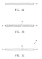
- FIGS. 3A-3C are schematic illustrations showing the manufacturing steps of a thin film substrate in accordance with the present invention.
- a sheet 34 with a thickness of between 20-50 ⁇ m is provided; for instance copper foil or a metal film with superior conductivity.
- a slot 33 is formed on the sheet 34 by a drilling process, an etching process or a punching process.
- the slot 33 separates a first conductive film 31 at one side from a second conductive film 32 at another side, that is, they are electrically isolated from each other, as shown in FIG. 3B .
- an insulating dielectric material 35 is filled in the slot 33 so that the manufacture of a thin film substrate 30 is finished.
- the insulating dielectric material 35 can be SiO, SiN, SiON, TaO, AlO, TiO, AlN, TiN, epoxy resin, silicone or polymer.
- the electrical insulation between the first conductive film 31 and second conductive film 32 is improved, and the thin film substrate 30 is more rigid, as shown in FIG. 3C .
- FIG. 4A is a cross-sectional diagram of the package structure of a compound semiconductor device in accordance with the present invention.
- a compound semiconductor device 40 utilizes the die-bonding technology to adhere a compound semiconductor die 43 to the first conductive film 31 of the thin film substrate 30, that is, the die 43 is mounted on the surface of the first conductive film 31 by a die-bonding adhesive 47.
- the die 43 can be an LED die, a laser diode die or a photodiode die.
- the die 43 and thin film substrate 30 are electrically connected to each other through metal wires 44 so that the thin film substrate 30 acts as the package carrier of the die 43 and metal wires 44.
- a transparent encapsulation material 46 overlays the die 43, metal wires 44, and thin film substrate 30 in order to provide anti-moisture and protection effects.
- the transparent encapsulation material 46 can be epoxy resin or silicone.
- FIG. 4B is a top view of the compound semiconductor device in FIG. 4A .
- a portion of the transparent encapsulation material 46 is removed.
- Two metal wires 44 respectively go from the surface of the die 43 toward the first conductive film 31 and the second conductive film 32, and connect them.
- FIG. 5 is a cross-sectional diagram of the package structure of a compound semiconductor device in accordance with another embodiment of the present invention.
- the compound semiconductor device 50 utilizes a flip-chip bonding process to mount the die 43 on the thin film substrate 30 through bumps 54.
- the active surface of the die 43 faces the thin film substrate 30, and tin balls are utilized to connect the bonding pads of the die 43 and thin film substrate 30 to form the bumps 54.
- the bumps 54 are melted due to solder flux after a reflow process, and solidify to electrically connect them.
- a transparent encapsulation material 46 overlays the die 43, metal wires 44, and thin film substrate 30 in order to have anti-moisture and protection effects.
- there are several advantages such as short current paths and excellent heat dissipation.
- the present invention can reduce the loop height of the metal wires.
- FIG. 6 is a cross-sectional diagram of the package structure of a compound semiconductor device in accordance with another embodiment of the present invention.
- the thickness of the package structure is further reduced and the illumination brightness of the device is increased.
- a die-bonding groove 411 is formed on the first conductive film 31' of the thin film substrate 30a, and a reflecting layer 412 is deposited on the sidewalls and bottom of the die-bonding groove 411.
- the die-bonding groove 411 can be formed by a photolithography etching process, an electroforming process and a drilling process.
- the die 43 is adhered to the bottom of the die-bonding groove 411, and the die-bonding groove 411 acts as a cup-like reflective cavity.
- the brightness of the compound semiconductor device 60 is improved.
- another advantage is that when the die 43 is placed in the die-bonding groove 411 and the metal wires 44 electrically connect the die 44 and thin film substrate 30a, the height of the wire loop of the gold wires is significantly reduced so as to further reduce the thickness of the entire package structure.
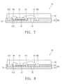
- FIG. 7 is a cross-sectional diagram of the package structure of a compound semiconductor device in accordance with another embodiment of the present invention. Compared with the previous embodiment, this embodiment further reduces the thickness of the package structure.
- a wire-bonding groove 413 is formed on the first conductive film 31'' of the thin film substrate 30b for one of the metal wires 44 to indicate the melting location of a second bond.
- a wire-bonding groove 421 is formed on the second conductive film 32' for another of the metal wires 44 to indicate the melting location of a second bond. Because the second bond of the metal wire 44 is descended to the wire-bonding groove, the thickness of the package structure of the compound semiconductor device 60 is reduced.
- the die-bonding groove and wire-bonding groove are formed by a photolithography etching process, an electroforming process and a drilling process. Furthermore, a patterned insulating material layer 36 can be formed on the thin film substrate 30, and a die-bonding groove 411 and wire-bonding grooves 413 and 421 are formed on the insulating material layer 36, as shown in FIG. 8 . Therefore, the thickness of the package structure of the compound semiconductor device 80 is reduced, which can prevent the metal wire 44 connected to the second conductive film 32 from short-circuit resulting from improperly contacting the first conductive film 31.
- FIGS. 9A-9D are schematic illustrations showing the formation of a die-bonding groove or a wire-bonding groove by an electroforming process.
- a patterned insulating material layer 36' such as a photoresist material is formed on the thin film substrate 30.
- a metal layer 37 is gradually grown on the surfaces of the first conductive film 31 and the second conductive film 32 uncovered by the insulating material layer 36' by an electroforming process.
- the insulating material layer 36' is removed (for example, a photoresist striping step) to expose the die-bonding groove 411 and wire-bonding grooves 413 and 421.
- a package structure of a compound semiconductor device comprising a thin film substrate, a die, at least one metal wire and a transparent encapsulation material.
- the thin film substrate comprises a first conductive film, a second conductive film, and an insulating dielectric material.
- the die is mounted on the surface of the first conductive film, and is electrically connected to the first conductive film and the second conductive film through the metal wire.
- the transparent encapsulation material overlays the first conductive film, second conductive film, and die.
- the surfaces of the first conductive film and second conductive film which is opposite the transparent encapsulation material act as electrodes.
- the insulating dielectric material is between the first conductive film and second conductive film.
Applications Claiming Priority (1)
| Application Number | Priority Date | Filing Date | Title |
|---|---|---|---|
| TW097105846A TW200937667A (en) | 2008-02-20 | 2008-02-20 | Package structure of chemical compound semiconductor device and fabricating method thereof |
Publications (3)
| Publication Number | Publication Date |
|---|---|
| EP2093811A2 true EP2093811A2 (de) | 2009-08-26 |
| EP2093811A3 EP2093811A3 (de) | 2013-05-29 |
| EP2093811B1 EP2093811B1 (de) | 2017-01-11 |
Family
ID=40433921
Family Applications (1)
| Application Number | Title | Priority Date | Filing Date |
|---|---|---|---|
| EP09153073.3A Not-in-force EP2093811B1 (de) | 2008-02-20 | 2009-02-18 | Gehäusestruktur eines Verbundhalbleiterbauelements |
Country Status (3)
| Country | Link |
|---|---|
| US (2) | US7893528B2 (de) |
| EP (1) | EP2093811B1 (de) |
| TW (1) | TW200937667A (de) |
Cited By (1)
| Publication number | Priority date | Publication date | Assignee | Title |
|---|---|---|---|---|
| US8502257B2 (en) | 2009-11-05 | 2013-08-06 | Visera Technologies Company Limited | Light-emitting diode package |
Families Citing this family (14)
| Publication number | Priority date | Publication date | Assignee | Title |
|---|---|---|---|---|
| TWI398933B (zh) * | 2008-03-05 | 2013-06-11 | Advanced Optoelectronic Tech | 積體電路元件之封裝結構及其製造方法 |
| KR20110018777A (ko) * | 2009-08-18 | 2011-02-24 | 삼성엘이디 주식회사 | 발광 다이오드 패키지 |
| TW201131708A (en) * | 2010-03-08 | 2011-09-16 | Harvatek Corp | LED package structure for increasing heat-dissipating efficiency and method of manufacturing the same |
| US8598612B2 (en) * | 2010-03-30 | 2013-12-03 | Micron Technology, Inc. | Light emitting diode thermally enhanced cavity package and method of manufacture |
| TWI472067B (zh) * | 2010-04-28 | 2015-02-01 | Lg Innotek Co Ltd | 光學封裝及其製造方法 |
| EP2418700B1 (de) | 2010-08-09 | 2017-11-01 | LG Innotek Co., Ltd. | Lichtemittierende Vorrichtung |
| KR101114719B1 (ko) | 2010-08-09 | 2012-02-29 | 엘지이노텍 주식회사 | 발광 소자 및 이를 구비한 조명 시스템 |
| KR101114197B1 (ko) * | 2010-08-09 | 2012-02-22 | 엘지이노텍 주식회사 | 발광 소자 및 이를 구비한 조명 시스템 |
| TWI425680B (zh) * | 2010-10-29 | 2014-02-01 | Advanced Optoelectronic Tech | 發光二極體封裝結構 |
| TWI424591B (zh) * | 2011-08-23 | 2014-01-21 | Jentech Prec Ind Co Ltd | 發光二極體封裝結構及其製造方法 |
| CN103022011B (zh) * | 2011-09-23 | 2015-10-07 | 讯芯电子科技(中山)有限公司 | 半导体封装结构及其制造方法 |
| JP5885499B2 (ja) * | 2011-12-27 | 2016-03-15 | 株式会社ディスコ | バイト切削方法 |
| KR20150031849A (ko) * | 2013-09-17 | 2015-03-25 | (주)포인트엔지니어링 | 칩 실장용 기판 및 칩 패키지 |
| EP3818298A4 (de) | 2018-07-03 | 2022-03-23 | Glowgadget, LLC | Flexibles leuchtpaneel und beleuchtungskörper |
Citations (1)
| Publication number | Priority date | Publication date | Assignee | Title |
|---|---|---|---|---|
| US20040090756A1 (en) | 2002-11-07 | 2004-05-13 | Kwun-Yo Ho | Chip packaging structure and manufacturing process thereof |
Family Cites Families (13)
| Publication number | Priority date | Publication date | Assignee | Title |
|---|---|---|---|---|
| JP4215306B2 (ja) | 1998-08-27 | 2009-01-28 | シチズン電子株式会社 | 半導体のパッケージおよびその製造方法 |
| JP3945037B2 (ja) * | 1998-09-04 | 2007-07-18 | 松下電器産業株式会社 | 光電変換素子及びその製造方法 |
| JP2002232018A (ja) * | 2000-11-28 | 2002-08-16 | Nippon Telegr & Teleph Corp <Ntt> | 紫外光源の作製方法および紫外光源部品並びに光学装置の作製方法 |
| DE10228634A1 (de) * | 2002-06-26 | 2004-01-22 | Osram Opto Semiconductors Gmbh | Oberflächenmontierbare Miniatur-Lumineszenz-und/oder Photo-Diode und Verfahren zu deren Herstellung |
| EP1525619A1 (de) * | 2002-07-31 | 2005-04-27 | Osram Opto Semiconductors GmbH | Oberflächenmontierbares halbleiterbauelement und verfahren zu dessen herstellung |
| JP3910171B2 (ja) | 2003-02-18 | 2007-04-25 | シャープ株式会社 | 半導体発光装置、その製造方法および電子撮像装置 |
| US7276782B2 (en) * | 2003-10-31 | 2007-10-02 | Harvatek Corporation | Package structure for semiconductor |
| DE10353679A1 (de) * | 2003-11-17 | 2005-06-02 | Siemens Ag | Kostengünstige, miniaturisierte Aufbau- und Verbindungstechnik für LEDs und andere optoelektronische Module |
| US7183588B2 (en) * | 2004-01-08 | 2007-02-27 | Avago Technologies Ecbu Ip (Singapore) Pte. Ltd. | Light emission device |
| JP4608294B2 (ja) | 2004-11-30 | 2011-01-12 | 日亜化学工業株式会社 | 樹脂成形体及び表面実装型発光装置並びにそれらの製造方法 |
| US20060131708A1 (en) * | 2004-12-16 | 2006-06-22 | Ng Kee Y | Packaged electronic devices, and method for making same |
| US7301225B2 (en) * | 2006-02-28 | 2007-11-27 | Freescale Semiconductor, Inc. | Multi-row lead frame |
| US20090026470A1 (en) * | 2007-07-23 | 2009-01-29 | Novalite Optronics Corp. | Super thin side-view light-emitting diode (led) package and fabrication method thereof |
-
2008
- 2008-02-20 TW TW097105846A patent/TW200937667A/zh unknown
-
2009
- 2009-02-13 US US12/370,923 patent/US7893528B2/en active Active - Reinstated
- 2009-02-18 EP EP09153073.3A patent/EP2093811B1/de not_active Not-in-force
-
2010
- 2010-08-13 US US12/856,052 patent/US8298861B2/en not_active Expired - Fee Related
Patent Citations (1)
| Publication number | Priority date | Publication date | Assignee | Title |
|---|---|---|---|---|
| US20040090756A1 (en) | 2002-11-07 | 2004-05-13 | Kwun-Yo Ho | Chip packaging structure and manufacturing process thereof |
Cited By (1)
| Publication number | Priority date | Publication date | Assignee | Title |
|---|---|---|---|---|
| US8502257B2 (en) | 2009-11-05 | 2013-08-06 | Visera Technologies Company Limited | Light-emitting diode package |
Also Published As
| Publication number | Publication date |
|---|---|
| US8298861B2 (en) | 2012-10-30 |
| EP2093811B1 (de) | 2017-01-11 |
| TW200937667A (en) | 2009-09-01 |
| US7893528B2 (en) | 2011-02-22 |
| US20100304535A1 (en) | 2010-12-02 |
| US20090206358A1 (en) | 2009-08-20 |
| EP2093811A3 (de) | 2013-05-29 |
Similar Documents
| Publication | Publication Date | Title |
|---|---|---|
| EP2093811B1 (de) | Gehäusestruktur eines Verbundhalbleiterbauelements | |
| EP2897182B1 (de) | Lichtemittierende Vorrichtung | |
| US20090022198A1 (en) | Package structure of compound semiconductor device and fabricating method thereof | |
| JP6131048B2 (ja) | Ledモジュール | |
| CN102185091B (zh) | 一种发光二极管器件及其制造方法 | |
| US8344406B2 (en) | Light emitting diode package and manufacturing method thereof | |
| JP2005322937A (ja) | フレキシブル基板を備えた半導体発光素子 | |
| US20100096746A1 (en) | Package module structure of compound semiconductor devices and fabricating method thereof | |
| US20070290307A1 (en) | Light emitting diode module | |
| CN102160197A (zh) | 光电元件封装基座 | |
| US20120056223A1 (en) | Led package structure and packaging method thereof | |
| US9425373B2 (en) | Light emitting module | |
| JP2012109521A (ja) | Ledモジュール装置及びその製造方法 | |
| US20110181182A1 (en) | Top view light emitting device package and fabrication method thereof | |
| CN103579129B (zh) | 半导体元件安装构件以及半导体装置 | |
| CN101546737B (zh) | 化合物半导体元件的封装结构及其制造方法 | |
| JP2007005722A (ja) | 光半導体素子用外囲器およびそれを用いた光半導体装置 | |
| JP2005123657A (ja) | チップ型発光素子およびその製造方法 | |
| JP2012165016A (ja) | 発光装置 | |
| TWI393273B (zh) | 發光二極體組件之製造方法 | |
| JP2006279080A (ja) | 発光素子ウエハの固定方法 | |
| KR101363980B1 (ko) | 광 모듈 및 그 제조 방법 | |
| JP5861356B2 (ja) | 光半導体装置用反射部材付リードフレーム、光半導体装置用リードフレーム、光半導体装置用リードフレーム基板、光半導体装置、および、光半導体装置用反射部材付リードフレームの製造方法、並びに、光半導体装置の製造方法 | |
| TW201025676A (en) | Compound semiconductor device package module structure and fabricating method thereof | |
| KR101129002B1 (ko) | 광 패키지 및 그 제조 방법 |
Legal Events
| Date | Code | Title | Description |
|---|---|---|---|
| PUAI | Public reference made under article 153(3) epc to a published international application that has entered the european phase |
Free format text: ORIGINAL CODE: 0009012 |
|
| AK | Designated contracting states |
Kind code of ref document: A2 Designated state(s): AT BE BG CH CY CZ DE DK EE ES FI FR GB GR HR HU IE IS IT LI LT LU LV MC MK MT NL NO PL PT RO SE SI SK TR |
|
| AX | Request for extension of the european patent |
Extension state: AL BA RS |
|
| PUAL | Search report despatched |
Free format text: ORIGINAL CODE: 0009013 |
|
| AK | Designated contracting states |
Kind code of ref document: A3 Designated state(s): AT BE BG CH CY CZ DE DK EE ES FI FR GB GR HR HU IE IS IT LI LT LU LV MC MK MT NL NO PL PT RO SE SI SK TR |
|
| AX | Request for extension of the european patent |
Extension state: AL BA RS |
|
| RIC1 | Information provided on ipc code assigned before grant |
Ipc: H01L 31/0203 20060101AFI20130424BHEP Ipc: H01L 33/48 20100101ALI20130424BHEP |
|
| 17P | Request for examination filed |
Effective date: 20131129 |
|
| RBV | Designated contracting states (corrected) |
Designated state(s): AT BE BG CH CY CZ DE DK EE ES FI FR GB GR HR HU IE IS IT LI LT LU LV MC MK MT NL NO PL PT RO SE SI SK TR |
|
| RBV | Designated contracting states (corrected) |
Designated state(s): AT BE BG CH CY CZ DE DK EE ES FI FR GB GR HR HU IE IS IT LI LT LU LV MC MK MT NL NO PL PT RO SE SI SK TR |
|
| AKX | Designation fees paid |
Designated state(s): AT BE BG CH CY CZ DE DK EE ES FI FR GB GR HR HU IE IS IT LI LT LU LV MC MK MT NL NO PL PT RO SE SI SK TR |
|
| 17Q | First examination report despatched |
Effective date: 20160428 |
|
| REG | Reference to a national code |
Ref country code: DE Ref legal event code: R079 Ref document number: 602009043642 Country of ref document: DE Free format text: PREVIOUS MAIN CLASS: H01L0033000000 Ipc: H01L0031020300 |
|
| GRAP | Despatch of communication of intention to grant a patent |
Free format text: ORIGINAL CODE: EPIDOSNIGR1 |
|
| RIC1 | Information provided on ipc code assigned before grant |
Ipc: H01L 33/62 20100101ALI20160829BHEP Ipc: H01L 31/0203 20060101AFI20160829BHEP Ipc: H01L 33/48 20100101ALI20160829BHEP |
|
| INTG | Intention to grant announced |
Effective date: 20161005 |
|
| GRAS | Grant fee paid |
Free format text: ORIGINAL CODE: EPIDOSNIGR3 |
|
| GRAA | (expected) grant |
Free format text: ORIGINAL CODE: 0009210 |
|
| AK | Designated contracting states |
Kind code of ref document: B1 Designated state(s): AT BE BG CH CY CZ DE DK EE ES FI FR GB GR HR HU IE IS IT LI LT LU LV MC MK MT NL NO PL PT RO SE SI SK TR |
|
| REG | Reference to a national code |
Ref country code: GB Ref legal event code: FG4D |
|
| REG | Reference to a national code |
Ref country code: CH Ref legal event code: EP |
|
| REG | Reference to a national code |
Ref country code: AT Ref legal event code: REF Ref document number: 861977 Country of ref document: AT Kind code of ref document: T Effective date: 20170115 |
|
| REG | Reference to a national code |
Ref country code: IE Ref legal event code: FG4D |
|
| REG | Reference to a national code |
Ref country code: FR Ref legal event code: PLFP Year of fee payment: 9 |
|
| REG | Reference to a national code |
Ref country code: DE Ref legal event code: R096 Ref document number: 602009043642 Country of ref document: DE |
|
| REG | Reference to a national code |
Ref country code: LT Ref legal event code: MG4D |
|
| REG | Reference to a national code |
Ref country code: NL Ref legal event code: MP Effective date: 20170111 |
|
| PG25 | Lapsed in a contracting state [announced via postgrant information from national office to epo] |
Ref country code: BE Free format text: LAPSE BECAUSE OF NON-PAYMENT OF DUE FEES Effective date: 20170228 |
|
| REG | Reference to a national code |
Ref country code: AT Ref legal event code: MK05 Ref document number: 861977 Country of ref document: AT Kind code of ref document: T Effective date: 20170111 |
|
| PG25 | Lapsed in a contracting state [announced via postgrant information from national office to epo] |
Ref country code: NL Free format text: LAPSE BECAUSE OF FAILURE TO SUBMIT A TRANSLATION OF THE DESCRIPTION OR TO PAY THE FEE WITHIN THE PRESCRIBED TIME-LIMIT Effective date: 20170111 |
|
| PG25 | Lapsed in a contracting state [announced via postgrant information from national office to epo] |
Ref country code: IS Free format text: LAPSE BECAUSE OF FAILURE TO SUBMIT A TRANSLATION OF THE DESCRIPTION OR TO PAY THE FEE WITHIN THE PRESCRIBED TIME-LIMIT Effective date: 20170511 Ref country code: GR Free format text: LAPSE BECAUSE OF FAILURE TO SUBMIT A TRANSLATION OF THE DESCRIPTION OR TO PAY THE FEE WITHIN THE PRESCRIBED TIME-LIMIT Effective date: 20170412 Ref country code: NO Free format text: LAPSE BECAUSE OF FAILURE TO SUBMIT A TRANSLATION OF THE DESCRIPTION OR TO PAY THE FEE WITHIN THE PRESCRIBED TIME-LIMIT Effective date: 20170411 Ref country code: HR Free format text: LAPSE BECAUSE OF FAILURE TO SUBMIT A TRANSLATION OF THE DESCRIPTION OR TO PAY THE FEE WITHIN THE PRESCRIBED TIME-LIMIT Effective date: 20170111 Ref country code: FI Free format text: LAPSE BECAUSE OF FAILURE TO SUBMIT A TRANSLATION OF THE DESCRIPTION OR TO PAY THE FEE WITHIN THE PRESCRIBED TIME-LIMIT Effective date: 20170111 Ref country code: LT Free format text: LAPSE BECAUSE OF FAILURE TO SUBMIT A TRANSLATION OF THE DESCRIPTION OR TO PAY THE FEE WITHIN THE PRESCRIBED TIME-LIMIT Effective date: 20170111 |
|
| PG25 | Lapsed in a contracting state [announced via postgrant information from national office to epo] |
Ref country code: PT Free format text: LAPSE BECAUSE OF FAILURE TO SUBMIT A TRANSLATION OF THE DESCRIPTION OR TO PAY THE FEE WITHIN THE PRESCRIBED TIME-LIMIT Effective date: 20170511 Ref country code: ES Free format text: LAPSE BECAUSE OF FAILURE TO SUBMIT A TRANSLATION OF THE DESCRIPTION OR TO PAY THE FEE WITHIN THE PRESCRIBED TIME-LIMIT Effective date: 20170111 Ref country code: SE Free format text: LAPSE BECAUSE OF FAILURE TO SUBMIT A TRANSLATION OF THE DESCRIPTION OR TO PAY THE FEE WITHIN THE PRESCRIBED TIME-LIMIT Effective date: 20170111 Ref country code: LV Free format text: LAPSE BECAUSE OF FAILURE TO SUBMIT A TRANSLATION OF THE DESCRIPTION OR TO PAY THE FEE WITHIN THE PRESCRIBED TIME-LIMIT Effective date: 20170111 Ref country code: AT Free format text: LAPSE BECAUSE OF FAILURE TO SUBMIT A TRANSLATION OF THE DESCRIPTION OR TO PAY THE FEE WITHIN THE PRESCRIBED TIME-LIMIT Effective date: 20170111 Ref country code: PL Free format text: LAPSE BECAUSE OF FAILURE TO SUBMIT A TRANSLATION OF THE DESCRIPTION OR TO PAY THE FEE WITHIN THE PRESCRIBED TIME-LIMIT Effective date: 20170111 Ref country code: BG Free format text: LAPSE BECAUSE OF FAILURE TO SUBMIT A TRANSLATION OF THE DESCRIPTION OR TO PAY THE FEE WITHIN THE PRESCRIBED TIME-LIMIT Effective date: 20170411 |
|
| REG | Reference to a national code |
Ref country code: CH Ref legal event code: PL |
|
| REG | Reference to a national code |
Ref country code: DE Ref legal event code: R097 Ref document number: 602009043642 Country of ref document: DE |
|
| PG25 | Lapsed in a contracting state [announced via postgrant information from national office to epo] |
Ref country code: SK Free format text: LAPSE BECAUSE OF FAILURE TO SUBMIT A TRANSLATION OF THE DESCRIPTION OR TO PAY THE FEE WITHIN THE PRESCRIBED TIME-LIMIT Effective date: 20170111 Ref country code: CZ Free format text: LAPSE BECAUSE OF FAILURE TO SUBMIT A TRANSLATION OF THE DESCRIPTION OR TO PAY THE FEE WITHIN THE PRESCRIBED TIME-LIMIT Effective date: 20170111 Ref country code: EE Free format text: LAPSE BECAUSE OF FAILURE TO SUBMIT A TRANSLATION OF THE DESCRIPTION OR TO PAY THE FEE WITHIN THE PRESCRIBED TIME-LIMIT Effective date: 20170111 Ref country code: RO Free format text: LAPSE BECAUSE OF FAILURE TO SUBMIT A TRANSLATION OF THE DESCRIPTION OR TO PAY THE FEE WITHIN THE PRESCRIBED TIME-LIMIT Effective date: 20170111 Ref country code: CH Free format text: LAPSE BECAUSE OF NON-PAYMENT OF DUE FEES Effective date: 20170228 Ref country code: LI Free format text: LAPSE BECAUSE OF NON-PAYMENT OF DUE FEES Effective date: 20170228 Ref country code: IT Free format text: LAPSE BECAUSE OF FAILURE TO SUBMIT A TRANSLATION OF THE DESCRIPTION OR TO PAY THE FEE WITHIN THE PRESCRIBED TIME-LIMIT Effective date: 20170111 |
|
| PLBE | No opposition filed within time limit |
Free format text: ORIGINAL CODE: 0009261 |
|
| STAA | Information on the status of an ep patent application or granted ep patent |
Free format text: STATUS: NO OPPOSITION FILED WITHIN TIME LIMIT |
|
| REG | Reference to a national code |
Ref country code: IE Ref legal event code: MM4A |
|
| PG25 | Lapsed in a contracting state [announced via postgrant information from national office to epo] |
Ref country code: MC Free format text: LAPSE BECAUSE OF FAILURE TO SUBMIT A TRANSLATION OF THE DESCRIPTION OR TO PAY THE FEE WITHIN THE PRESCRIBED TIME-LIMIT Effective date: 20170111 Ref country code: DK Free format text: LAPSE BECAUSE OF FAILURE TO SUBMIT A TRANSLATION OF THE DESCRIPTION OR TO PAY THE FEE WITHIN THE PRESCRIBED TIME-LIMIT Effective date: 20170111 |
|
| 26N | No opposition filed |
Effective date: 20171012 |
|
| GBPC | Gb: european patent ceased through non-payment of renewal fee |
Effective date: 20170411 |
|
| PG25 | Lapsed in a contracting state [announced via postgrant information from national office to epo] |
Ref country code: LU Free format text: LAPSE BECAUSE OF NON-PAYMENT OF DUE FEES Effective date: 20170218 |
|
| REG | Reference to a national code |
Ref country code: FR Ref legal event code: PLFP Year of fee payment: 10 |
|
| REG | Reference to a national code |
Ref country code: BE Ref legal event code: MM Effective date: 20170228 |
|
| PG25 | Lapsed in a contracting state [announced via postgrant information from national office to epo] |
Ref country code: GB Free format text: LAPSE BECAUSE OF NON-PAYMENT OF DUE FEES Effective date: 20170411 Ref country code: SI Free format text: LAPSE BECAUSE OF FAILURE TO SUBMIT A TRANSLATION OF THE DESCRIPTION OR TO PAY THE FEE WITHIN THE PRESCRIBED TIME-LIMIT Effective date: 20170111 Ref country code: IE Free format text: LAPSE BECAUSE OF NON-PAYMENT OF DUE FEES Effective date: 20170218 |
|
| PG25 | Lapsed in a contracting state [announced via postgrant information from national office to epo] |
Ref country code: MT Free format text: LAPSE BECAUSE OF NON-PAYMENT OF DUE FEES Effective date: 20170218 |
|
| PG25 | Lapsed in a contracting state [announced via postgrant information from national office to epo] |
Ref country code: HU Free format text: LAPSE BECAUSE OF FAILURE TO SUBMIT A TRANSLATION OF THE DESCRIPTION OR TO PAY THE FEE WITHIN THE PRESCRIBED TIME-LIMIT; INVALID AB INITIO Effective date: 20090218 |
|
| PG25 | Lapsed in a contracting state [announced via postgrant information from national office to epo] |
Ref country code: CY Free format text: LAPSE BECAUSE OF NON-PAYMENT OF DUE FEES Effective date: 20170111 |
|
| PG25 | Lapsed in a contracting state [announced via postgrant information from national office to epo] |
Ref country code: MK Free format text: LAPSE BECAUSE OF FAILURE TO SUBMIT A TRANSLATION OF THE DESCRIPTION OR TO PAY THE FEE WITHIN THE PRESCRIBED TIME-LIMIT Effective date: 20170111 |
|
| REG | Reference to a national code |
Ref country code: DE Ref legal event code: R082 Ref document number: 602009043642 Country of ref document: DE |
|
| PG25 | Lapsed in a contracting state [announced via postgrant information from national office to epo] |
Ref country code: TR Free format text: LAPSE BECAUSE OF FAILURE TO SUBMIT A TRANSLATION OF THE DESCRIPTION OR TO PAY THE FEE WITHIN THE PRESCRIBED TIME-LIMIT Effective date: 20170111 |
|
| PGFP | Annual fee paid to national office [announced via postgrant information from national office to epo] |
Ref country code: DE Payment date: 20200204 Year of fee payment: 12 |
|
| PGFP | Annual fee paid to national office [announced via postgrant information from national office to epo] |
Ref country code: FR Payment date: 20200127 Year of fee payment: 12 |
|
| REG | Reference to a national code |
Ref country code: DE Ref legal event code: R119 Ref document number: 602009043642 Country of ref document: DE |
|
| PG25 | Lapsed in a contracting state [announced via postgrant information from national office to epo] |
Ref country code: FR Free format text: LAPSE BECAUSE OF NON-PAYMENT OF DUE FEES Effective date: 20210228 Ref country code: DE Free format text: LAPSE BECAUSE OF NON-PAYMENT OF DUE FEES Effective date: 20210901 |