EP2093368A2 - Laibungsanschlussprofil für an Putz angrenzende Bauteile - Google Patents
Laibungsanschlussprofil für an Putz angrenzende Bauteile Download PDFInfo
- Publication number
- EP2093368A2 EP2093368A2 EP09153104A EP09153104A EP2093368A2 EP 2093368 A2 EP2093368 A2 EP 2093368A2 EP 09153104 A EP09153104 A EP 09153104A EP 09153104 A EP09153104 A EP 09153104A EP 2093368 A2 EP2093368 A2 EP 2093368A2
- Authority
- EP
- European Patent Office
- Prior art keywords
- sealing
- connection profile
- leg
- component
- strip
- Prior art date
- Legal status (The legal status is an assumption and is not a legal conclusion. Google has not performed a legal analysis and makes no representation as to the accuracy of the status listed.)
- Granted
Links
- 239000011505 plaster Substances 0.000 title claims description 10
- 238000007789 sealing Methods 0.000 claims abstract description 96
- 239000000853 adhesive Substances 0.000 claims abstract description 22
- 230000001070 adhesive effect Effects 0.000 claims abstract description 20
- 239000004033 plastic Substances 0.000 claims abstract description 4
- 239000006260 foam Substances 0.000 claims description 18
- 230000001681 protective effect Effects 0.000 claims description 2
- 238000011144 upstream manufacturing Methods 0.000 abstract description 2
- 230000009977 dual effect Effects 0.000 abstract 1
- 239000000463 material Substances 0.000 abstract 1
- 239000012790 adhesive layer Substances 0.000 description 3
- 239000002390 adhesive tape Substances 0.000 description 3
- 238000009434 installation Methods 0.000 description 2
- 238000010521 absorption reaction Methods 0.000 description 1
- 230000015572 biosynthetic process Effects 0.000 description 1
- 238000010276 construction Methods 0.000 description 1
- 230000000694 effects Effects 0.000 description 1
- 239000003000 extruded plastic Substances 0.000 description 1
- 239000004744 fabric Substances 0.000 description 1
- 238000009413 insulation Methods 0.000 description 1
- 238000004519 manufacturing process Methods 0.000 description 1
- 230000003014 reinforcing effect Effects 0.000 description 1
- 238000010008 shearing Methods 0.000 description 1
Images


Classifications
-
- E—FIXED CONSTRUCTIONS
- E04—BUILDING
- E04F—FINISHING WORK ON BUILDINGS, e.g. STAIRS, FLOORS
- E04F13/00—Coverings or linings, e.g. for walls or ceilings
- E04F13/02—Coverings or linings, e.g. for walls or ceilings of plastic materials hardening after applying, e.g. plaster
- E04F13/04—Bases for plaster
- E04F13/06—Edge-protecting borders
- E04F13/068—Edge-protecting borders combined with mesh material or the like to allow plaster to bond therewith
-
- E—FIXED CONSTRUCTIONS
- E04—BUILDING
- E04G—SCAFFOLDING; FORMS; SHUTTERING; BUILDING IMPLEMENTS OR AIDS, OR THEIR USE; HANDLING BUILDING MATERIALS ON THE SITE; REPAIRING, BREAKING-UP OR OTHER WORK ON EXISTING BUILDINGS
- E04G21/00—Preparing, conveying, or working-up building materials or building elements in situ; Other devices or measures for constructional work
- E04G21/24—Safety or protective measures preventing damage to building parts or finishing work during construction
- E04G21/30—Safety or protective measures preventing damage to building parts or finishing work during construction against mechanical damage or dirt, e.g. guard covers of stairs
-
- E—FIXED CONSTRUCTIONS
- E06—DOORS, WINDOWS, SHUTTERS, OR ROLLER BLINDS IN GENERAL; LADDERS
- E06B—FIXED OR MOVABLE CLOSURES FOR OPENINGS IN BUILDINGS, VEHICLES, FENCES OR LIKE ENCLOSURES IN GENERAL, e.g. DOORS, WINDOWS, BLINDS, GATES
- E06B1/00—Border constructions of openings in walls, floors, or ceilings; Frames to be rigidly mounted in such openings
- E06B1/62—Tightening or covering joints between the border of openings and the frame or between contiguous frames
-
- E—FIXED CONSTRUCTIONS
- E04—BUILDING
- E04F—FINISHING WORK ON BUILDINGS, e.g. STAIRS, FLOORS
- E04F13/00—Coverings or linings, e.g. for walls or ceilings
- E04F13/02—Coverings or linings, e.g. for walls or ceilings of plastic materials hardening after applying, e.g. plaster
- E04F13/04—Bases for plaster
- E04F13/06—Edge-protecting borders
- E04F2013/063—Edge-protecting borders for corners
-
- E—FIXED CONSTRUCTIONS
- E06—DOORS, WINDOWS, SHUTTERS, OR ROLLER BLINDS IN GENERAL; LADDERS
- E06B—FIXED OR MOVABLE CLOSURES FOR OPENINGS IN BUILDINGS, VEHICLES, FENCES OR LIKE ENCLOSURES IN GENERAL, e.g. DOORS, WINDOWS, BLINDS, GATES
- E06B1/00—Border constructions of openings in walls, floors, or ceilings; Frames to be rigidly mounted in such openings
- E06B1/62—Tightening or covering joints between the border of openings and the frame or between contiguous frames
- E06B2001/624—Tightening or covering joints between the border of openings and the frame or between contiguous frames with parts to be embedded in the stucco layer or otherwise linked to this layer
Definitions
- the invention relates to a soffit connection profile for plaster adjacent components, in particular for window or door frames, with a sealing leg, which component side has a sealing tape with a holding means for attachment to the component.
- Sealing tapes such as double adhesive tapes, with which soffit connection profiles are fastened to window or door sills, have the disadvantage that relative movements (tensile and shear movements) between the adjoining built-in part and the facade can be absorbed only to a very limited extent.
- the extensibility of the sealing strip is about 10% of the strip thickness.
- a sealing tape with a thickness of 4 mm can, for example, absorb movements of the facade away from the window or door frame only to the extent of approx. 0.4 mm.
- the sealing tape is detached from the adjacent component, creating unsightly joints and gaps, in which moisture can penetrate.
- connection profile is known, which is attached to a component with a self-adhesive sealing strip made of a foam sheet.
- a self-adhesive sealing strip made of a foam sheet.
- an elastic sealing lip is upstream of the weather side, which rests against the component in the installed state. A detachment of the sealing strip from the mounting part in relative movements of the components, however, is not prevented by this construction.
- a soffit connection profile which allows both a vertical movement as well as a pulling movement in a direction away from the adjacent component to a sufficient extent, is in the EP 1 479 848 A1 described.
- This profile has a sealing leg which is equipped on the component side with a sealing strip and connected in a U-shaped arrangement with an outer leg. A relative movement between sealing leg and outer leg is received by a flexible tab which connects the sealing leg with the outer leg.
- the outer leg has a substantially perpendicular thereto angled Einputzsteg, and a Putzarm istsgewebe.
- the outer leg is further with a component in the direction protruding cover strip, which projects beyond the gap between the sealing leg and outer leg.
- On both sides of the sealing strip in the direction of component projecting sealing lips made of a soft or hard plastic are arranged. The disadvantage is only the complicated structure and the great effort to produce such a profile.
- the object of the invention is to propose a soffit connection profile for components adjacent to plaster, which is suitable to compensate for shearing movements, or tensile loads away from the adjacent component, but the manufacture and handling of the profile during installation should be simplified.
- sealing leg and the sealing strip form a receiving space in which an expanding, elastic foam element is arranged.
- the resulting gap is advantageously closed immediately by the expanding foam element.
- the sealing tape is fastened with an adhesive on the sealing leg of the soffit connection profile, whose holding force is adjusted in relation to that of the component-side adhesive such that the sealing strip detaches from the sealing leg during a tensile or shear movement and releases the expandable, elastic foam element.
- the sealing tape can be designed for example as a double-sided adhesive tape that is self-adhesive on both sides.
- the adhesive layer of the sealing strip can be reduced compared to the opposite side, whereby the adhesive bond dissolves under tensile or shear loads and the foam element or the foam strip can expand accordingly.
- the different adhesive forces on both sides of the sealing strip can also be realized by different sized adhesive surfaces, which arise from the fact that the receiving space for the expanding elastic foam element is formed by a recess of the sealing leg.
- the adhesive strength between the sealing strip and the sealing leg must be sufficiently great to ensure that the expanding foam element remains in a compressed state during storage and installation of the reveal connection profile.
- the soffit connection profile is constructed in two parts and one on the sealing leg having by means of a latching connection attachable Einputzsteg, wherein the latching connection defines the Einputzsteg displaced in the direction of the profile longitudinal axis.
- a further embodiment of the invention provides that the sealing leg is designed angled, the adjacent component, such as a roller shutter rail, surrounds and has a cover strip, which forms a plaster receiving space together with a Einputzsteg which is aligned substantially parallel to the sealing leg.
- a sealing leg 2 which is attached to the component 20 with the interposition of a sealing strip 3 with an adhesive 4 (eg adhesive layer).
- an adhesive 5 eg adhesive layer
- the adhesive force - for example, due to the smaller adhesive surfaces or a lower adhesive application - is smaller than that of Adhesive 4 to the component 20.
- the sealing strip 3 together with adhesive 4, 5 may for example be designed as a double-sided adhesive tape.
- a sealing web 6 protruding in the direction of the component 20 is arranged laterally of the sealing strip 3 and slidably bears against the narrow side 7 of the sealing strip 3.
- the sealing leg 2 and the sealing strip 3 form when installing the soffit connection profile 1 in a cross-section, for example, rectangular, closed receiving space 12, in which an expanding, preferably permanently elastic foam element 13 is arranged in its compressed form.
- the sealing strip 3 is fastened with an adhesive 5 on the sealing leg 2, the holding force in relation to that of the component-side adhesive 4 is tuned such that in a tensile or shear movement, the sealing strip 3 from the sealing leg 2 dissolves and the expanding elastic foam element 13 free gives (see Fig. 3 )
- the sealing tape 3 remains stuck to the component 20 and it forms a gap s of about 2 mm to 3 mm between the upper contact surface of the sealing strip 3 and the underside of the sealing leg 2, which, however, at the front of the connection profile 1 by the sliding on the narrow side 7 of the sealing strip 3 adjacent sealing ridge 6 remains closed and in which the expanding elastic foam element 13 unfolds.
- an area arises in which the thermal insulation function of the connection profile is essentially taken over by the expanding elastic foam element 13.
- the receiving space 12 for the expanding foam element 13 is formed by a recess in the sealing leg 2.
- the soffit connection profile 1 is made in two parts.
- a Einputzsteg 9 ' is attached to the sealing leg 2 by means of a locking connection 14, wherein the locking connection 14 the Einputzsteg 9' defines slidably in the direction of the profile longitudinal axis.
- the latching connection 14 can consist of a groove arranged on the sealing leg 2 and a catch web 9 'integrally formed on the latching web.
- the sealing leg 2 of the embodiments according to Fig. 1 to Fig. 6 also has a cover strip 8 protruding at an angle ⁇ of approximately 20 ° to 45 ° in the direction of component 20, which together with a plastered web 9 or 9 ', which protrudes substantially vertically from the sealing leg 2 forms a Putzabilityraum.
- a reinforcing fabric 10 may be secured, for example by means of an extruded plastic strip 19.
- the L-shaped structure of sealing leg 2 and Einputzsteg 9, 9 ' serves to receive the outer edge of a Fassadendämmimplantations not shown.
- the sealing leg 2 on the weather side has a sealing web 6 protruding in the direction of the component 20. It is also possible to provide 3 sealing webs on both sides of the sealing strip.
- the sealing ridge 6 may be preceded by a fitting on the component 20, elastic sealing lip 21 made of hard or soft plastic.
- FIGS. 7 to 9 show a variant in which the connection profile 1 adjacent to a roller shutter rail 20.
- the sealing leg 2 is executed here angled, wherein the adjacent component 20, for example, a roller shutter rail, is partially encompassed.
- the sealing leg 2 has a cover strip 8, which forms a plaster receiving space together with a Einputzsteg 9, which is aligned parallel to the sealing leg 2 substantially.
- the cover strip 8 rests with a support web 22 on a weather-side outside of the component 20. Again, one is a relative movement away from the component 20 (according to arrow 11) possible, with a gap s is formed by the expanding foam element 13 is bridged (see Fig. 9 )
- the cover strip 8 has in a known manner a detachable protective leg 15, which may be fastened for example via a predetermined breaking point 16 on the cover strip 8.
Landscapes
- Engineering & Computer Science (AREA)
- Architecture (AREA)
- Civil Engineering (AREA)
- Structural Engineering (AREA)
- Mechanical Engineering (AREA)
- Building Environments (AREA)
- Door And Window Frames Mounted To Openings (AREA)
Abstract
Description
- Die Erfindung betrifft ein Laibungsanschlussprofil für an Putz angrenzende Bauteile, insbesondere für Fenster- oder Türstöcke, mit einem Dichtungsschenkel, welcher bauteilseitig ein Dichtungsband mit einem Haltemittel zur Befestigung am Bauteil aufweist.
- Dichtungsbänder, beispielsweise Doppelklebebänder, mit welchen Laibungsanschlussprofile an Fenster- oder Türstöcken befestigt werden, haben den Nachteil, dass Relativbewegungen (Zug- und Scherbewegungen) zwischen dem angrenzenden Einbauteil und der Fassade nur sehr eingeschränkt aufgenommen werden können. Üblicherweise liegt die Dehnungsfähigkeit des Dichtungsbandes bei ca. 10% der Bandstärke. Ein Dichtungsband mit 4 mm Dicke kann so zum Bespiel Bewegungen der Fassade weg vom Fenster- oder Türstock lediglich im Ausmaß von ca. 0,4 mm aufnehmen. Bei größeren Relativbewegungen wird das Dichtungsband vom angrenzenden Bauteil abgelöst, wodurch unansehnliche Fugen und Spalten entstehen, in welche Feuchte eindringen kann.
- In diesem Zusammenhang ist aus der
DE 200 11 013 U1 ein Laibungsanschlussprofil bekannt, welches mit einem selbstklebenden Dichtungsband aus einem Schaumstoff-Flachmaterial an einem Bauteil befestigt wird. Um das Dichtungsband gegen Witterungseinflüsse zu schützen, ist wetterseitig eine elastische Dichtlippe vorgelagert, die in eingebautem Zustand am Bauteil anliegt. Ein Ablösen des Dichtungsbandes vom Einbauteil bei Relativbewegungen der Bauteile wird allerdings durch diese Konstruktion nicht verhindert. - Ein Laibungsanschlussprofil, welches sowohl eine Vertikalbewegung als auch eine Zugbewegung in eine vom angrenzenden Bauteil wegführende Richtung in ausreichendem Ausmaß zulässt, wird in der
EP 1 479 848 A1 beschrieben. Dieses Profil weist einen Dichtungsschenkel auf, welcher bauteilseitig mit einem Dichtungsband ausgestattet und in einer U-förmigen Anordnung mit einem Außenschenkel verbunden ist. Eine Relativbewegung zwischen Dichtungsschenkel und Außenschenkel wird durch ein flexible Lasche aufgenommen, welche den Dichtungsschenkel mit dem Außenschenkel verbindet. Der Außenschenkel weist einen im Wesentlichen senkrecht dazu abgewinkelten Einputzsteg auf, sowie ein Putzarmierungsgewebe. Der Außenschenkel ist weiters mit einer in Richtung Bauteil ragenden Deckleiste ausgestattet, welche den Spalt zwischen Dichtungsschenkel und Außenschenkel überragt. Zu beiden Seiten des Dichtungsbandes sind in Richtung Bauteil ragende Dichtlippen aus einem Weich- oder Hartkunststoff angeordnet. Nachteilig ist lediglich der komplizierte Aufbau und der große Aufwand zur Herstellung eines derartigen Profils. - Aufgabe der Erfindung ist es, ein Laibungsanschlussprofil für an Putz angrenzende Bauteile vorzuschlagen, welches geeignet ist, Scherbewegungen, bzw. Zugbelastungen weg vom angrenzenden Bauteil auszugleichen, wobei jedoch die Herstellung und die Handhabung des Profils beim Einbau vereinfacht werden soll.
- Diese Aufgabe wird erfindungsgemäß dadurch gelöst, dass der Dichtungsschenkel und das Dichtungsband einen Aufnahmeraum bilden, in welchem ein expandierendes, elastisches Schaumstoffelement angeordnet ist. Bei der Ausbildung eines Spaltes, hervorgerufen durch eine Relativbewegung zwischen Fassade und Einbauteil, wird der entstehende Spalt in vorteilhafter Weise sofort durch das expandierende Schaumstoffelement verschlossen.
- Erfindungsgemäß ist das Dichtungsband mit einem Haftmittel am Dichtschenkel des Laibungsanschlussprofils befestigt, dessen Haltekraft im Verhältnis zu jener des bauteilseitigen Haftmittels derart abgestimmt ist, dass sich bei einer Zug- oder Scherbewegung das Dichtungsband vom Dichtungsschenkel löst und das expandiere, elastische Schaumstoffelement frei gibt. Dadurch ist die Aufnahme größerer Bewegungen nach Entkoppelung in sämtliche Richtungen gewährleistet. Das Dichtungsband kann beispielsweise als Doppelklebeband ausgebildet sein, dass auf beiden Seiten selbstklebend ist. Auf jener Seite, wo das expandierende Schaumstoffelement integriert ist, kann die Kleberauflage des Dichtbandes im Vergleich zur gegenüberliegenden Seite verringert sein, wodurch sich die Klebeverbindung bei Zug- oder Scherbelastungen löst und das Schaumstoffelement bzw. das Schaumstoffband entsprechend expandieren kann.
- Die unterschiedlichen Haftkräfte auf beiden Seiten des Dichtungsbandes können auch durch unterschiedlich große Klebeflächen realisiert werden, welche dadurch entstehen, dass der Aufnahmeraum für das expandierende, elastische Schaumstoffelement durch eine Aussparung des Dichtungsschenkels gebildet wird. Die Klebekraft zwischen Dichtungsband und Dichtungsschenkel muss jedenfalls ausreichend groß sein, um während der Lagerung und des Einbaues des Laibungsanschlussprofils dafür zu sorgen, dass das expandierende Schaumstoffelement in einem komprimierten Zustand verbleibt.
- Gemäß einer bevorzugten Ausführungsvariante der Erfindung ist vorgesehen, dass das Laibungsanschlussprofil zweiteilig aufgebaut ist und einen am Dichtungsschenkel mit Hilfe einer Rastverbindung befestigbaren Einputzsteg aufweist, wobei die Rastverbindung den Einputzsteg in Richtung der Profillängsachse verschiebbar festlegt.
- Eine weitere Ausführungsvariante der Erfindung sieht vor, dass der Dichtungsschenkel abgewinkelt ausgeführt ist, das angrenzende Bauteil, beispielsweise eine Rollladenschiene, umgreift und eine Deckleiste aufweist, welche zusammen mit einem Einputzsteg, der zum Dichtungsschenkel im Wesentlichen parallel ausgerichtet ist, einen Putzaufnahmeraum bildet.
- Die Erfindung wird im Folgenden anhand von Zeichnungen näher erläutert. Es zeigen:
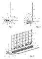
- Fig. 1
- ein erfindungsgemäßes einteiliges Laibungsanschlussprofil für an Putz angrenzende Bauteile in einer Schnittdarstellung;
- Fig. 2
- das Anschlussprofil gemäß
Fig. 1 in einer dreidimensionalen Darstellung; - Fig. 3
- das Anschlussprofil gemäß
Fig. 1 in einer Zugbeanspruchung weg vom Bauteil; - Fig. 4
- ein erfindungsgemäßes zweiteiliges Laibungsanschlussprofil in einer Schnittdarstellung;
- Fig. 5
- das Anschlussprofil gemäß
Fig. 4 in einer dreidimensionalen Darstellung; - Fig. 6
- das Anschlussprofil gemäß
Fig. 4 in einer Zugbeanspruchung weg vom Bauteil; - Fig. 7
- ein erfindungsgemäßes Anschlussprofil für Rollladenschienen in einer Schnittdarstellung;
- Fig. 8
- das Anschlussprofil gemäß
Fig. 7 in einer dreidimensionalen Darstellung; sowie - Fig. 9
- das Anschlussprofil gemäß
Fig. 7 in einer Zugbeanspruchung weg vom Bauteil. - Das in den
Fig. 1 bis Fig. 3 dargestellten einteilige Laibungsanschlussprofil 1 für an Putz angrenzende Bauteile 20 weist einen Dichtungsschenkel 2 auf, welcher unter Zwischenlage eines Dichtungsbandes 3 mit einem Haftmittel 4 (z.B. Kleberschicht) am Bauteil 20 befestigt wird. An den Kontaktflächen des Dichtungsbandes 3 zum Dichtungsschenkel 2 ist ebenfalls ein Haftmittel 5 (z.B. Kleberschicht) vorgesehen, dessen Haftkraft - beispielsweise aufgrund der kleineren Haftflächen oder eines geringeren Haftmittelauftrages - kleiner ist als jene des Haftmittels 4 zum Bauteil 20. Das Dichtungsband 3 samt Haftmittel 4, 5 kann beispielsweise als Doppelklebeband ausgeführt sein. Am Dichtungsschenkel 2 ist seitlich des Dichtungsbandes 3 ein in Richtung Bauteil 20 ragender Dichtsteg 6 angeordnet, der an der Schmalseite 7 des Dichtungsbandes 3 gleitend anliegt. - Der Dichtungsschenkel 2 und das Dichtungsband 3 bilden beim Einbau des Laibungsanschlussprofils 1 einen im Querschnitt beispielsweise rechteckförmigen, geschlossenen Aufnahmeraum 12, in welchem ein expandierendes, bevorzugt dauerelastisches Schaumstoffelement 13 in seiner komprimierten Form angeordnet ist. Das Dichtungsband 3 ist mit einem Haftmittel 5 am Dichtungsschenkel 2 befestigt, dessen Haltekraft im Verhältnis zur jener des bauteilseitigen Haftmittels 4 derart abgestimmt ist, dass sich bei einer Zug- oder Scherbewegung das Dichtungsband 3 vom Dichtungsschenkel 2 löst und das expandierende, elastische Schaumstoffelement 13 frei gibt (siehe
Fig. 3 ) - Im Fall einer Relativbewegung gemäß Pfeil 11 (siehe
Fig. 3 ) bleibt somit das Dichtungsband 3 am Bauteil 20 kleben und es bildet sich ein Spalt s von ca. 2 mm bis 3 mm zwischen der oberen Kontaktfläche des Dichtungsbandes 3 und der Unterseite des Dichtungsschenkels 2, welcher allerdings an der Vorderseite des Anschlussprofils 1 durch den gleitend an der Schmalseite 7 des Dichtungsbandes 3 anliegenden Dichtsteg 6 verschlossen bleibt und in welchem sich das expandierende, elastische Schaumstoffelement 13 entfaltet. Es entsteht somit ein Bereich, in welchem die Wärmedämmfunktion des Anschlussprofils im Wesentlichen durch das expandierende, elastische Schaumstoffelement 13 übernommen wird. - In den dargestellten Beispielen wird der Aufnahmeraum 12 für das expandierende Schaumstoffelement 13 durch eine Ausnehmung im Dichtungsschenkel 2 gebildet. Es wäre allerdings auch möglich, eine entsprechende Ausnehmung zumindest zum Teil im Dichtungsband 3 vorzusehen.
- In den
Fig. 4 bis Fig. 6 wird eine Ausführungsvariante der Erfindung dargestellt, bei welcher das Laibungsanschlussprofil 1 zweiteilig ausgeführt ist. Dabei ist am Dichtungsschenkel 2 mit Hilfe einer Rastverbindung 14 ein Einputzsteg 9' befestigt, wobei die Rastverbindung 14 den Einputzsteg 9' in Richtung der Profillängsachse verschiebbar festlegt. Wie aus dem dargestellten Beispiel ersichtlich, kann die Rastverbindung 14 aus einer am Dichtungsschenkel 2 angeordneten Nut und einem am Einputzsteg 9' angeformten Raststeg bestehen. - Der Dichtungsschenkel 2 der Ausführungsvarianten gemäß
Fig. 1 bis Fig. 6 weist weiters eine im Winkel α von ca. 20° bis 45° in Richtung Bauteil 20 ragende Deckleiste 8 auf, welche zusammen mit einem Einputzsteg 9 bzw. 9', welcher vom Dichtungsschenkel 2 im Wesentlichen senkrecht absteht, einen Putzaufnahmeraum bildet. Am Einputzsteg 9, 9' kann ein Armierungsgewebe 10 beispielsweise mit Hilfe eines aufextrudierten Kunststoffstreifens 19 befestigt sein. Die L-förmigen Struktur aus Dichtungsschenkel 2 und Einputzsteg 9, 9' dient zur Aufnahme der Außenkante eines nicht weiter dargestellten Fassadendämmelementes. - In den Ausführungsvarianten gemäß
Fig. 1 bis Fig. 6 weist der Dichtungsschenkel 2 wetterseitig einen in Richtung Bauteil 20 ragenden Dichtsteg 6 auf. Es ist auch möglich, beiderseits des Dichtungsbandes 3 Dichtstege vorzusehen. Dem Dichtsteg 6 kann eine am Bauteil 20 anliegende, elastische Dichtlippe 21 aus Hart- oder Weichkunststoff vorgelagert sein. - Die
Fig. 7 bis Fig. 9 zeigen eine Ausführungsvariante, bei welcher das Anschlussprofil 1 an eine Rollladenschiene 20 angrenzt. Der Dichtungsschenkel 2 ist hier abgewinkelt ausgeführt, wobei das angrenzende Bauteil 20, beispielsweise eine Rollladenschiene, teilweise umgriffen wird. Der Dichtungsschenkel 2 weist eine Deckleiste 8 auf, welche zusammen mit einem Einputzsteg 9, der zum Dichtungsschenkel 2 im Wesentlichen parallel ausgerichtet ist, einen Putzaufnahmeraum bildet. Die Deckleiste 8 liegt mit einem Stützsteg 22 an einer wetterseitigen Außenseite des Bauteils 20 an. Auch hier ist eine ist eine Relativbewegung weg vom Bauteil 20 (gemäß Pfeil 11) möglich, wobei ein Spalt s entsteht der vom expandierenden Schaumstoffelement 13 überbrückt wird (sieheFig. 9 ) - Die Deckleiste 8 weist in bekannter Weise einen abtrennbaren Schutzschenkel 15 auf, welcher beispielsweise über eine Sollbruchstelle 16 an der Deckleiste 8 befestigt sein kann.
- Zum besseren Verkrallen des Anschlussprofils 1 im Verputz kann der freie Rand des Einputzsteges 9, 9' eine Verzahnung 17 und/oder Durchbrüche 18 aufweisen.
Claims (12)
- Laibungsanschlussprofil (1) für an Putz angrenzende Bauteile (20), insbesondere für Fensterstöcke, Türstöcke oder Rollladenschienen, mit einem Dichtungsschenkel (2), welcher bauteilseitig ein Dichtungsband (3) mit einem Haftmittel (4) zur Befestigung am Bauteil (20) aufweist, dadurch gekennzeichnet, dass der Dichtungsschenkel (2) und das Dichtungsband (3) einen Aufnahmeraum (12) bilden, in welchem ein expandierendes, elastisches Schaumstoffelement (13) angeordnet ist.
- Laibungsanschlussprofil (1) nach Anspruch 1, dadurch gekennzeichnet, dass das Dichtungsband (3) mit einem Haftmittel (5) am Dichtungsschenkel (2) befestigt ist, dessen Haltekraft im Verhältnis zu jener des bauteilseitigen Haftmittels (4) derart abgestimmt ist, dass sich bei einer Zug- oder Scherbelastung das Dichtungsband (3) vom Dichtungsschenkel (2) löst und das expandierende, elastische Schaumstoffelement (13) frei gibt.
- Laibungsanschlussprofil (1) nach Anspruch 1 oder 2, dadurch gekennzeichnet, dass der Aufnahmeraum (12) für das expandierende, elastische Schaumstoffelement (13) durch eine Aussparung des Dichtungsschenkels (2) gebildet ist.
- Laibungsanschlussprofil (1) nach einem der Ansprüche 1 bis 3, dadurch gekennzeichnet, dass am Dichtungsschenkel (2) zumindest ein in Richtung Bauteil (20) ragender Dichtsteg (6) angeordnet ist, der an einer Schmalseite (7) des Dichtungsbandes (3) gleitend anliegt.
- Laibungsanschlussprofil (1) nach einem der Ansprüche 1 bis 4, dadurch gekennzeichnet, dass das Laibungsanschlussprofil (1) zweiteilig aufgebaut ist und einen am Dichtungsschenkel (2) mit Hilfe einer Rastverbindung (14) befestigbaren Einputzsteg (9') aufweist, wobei die Rastverbindung (14) den Einputzsteg (9') in Richtung der Profillängsachse verschiebbar festlegt.
- Laibungsanschlussprofil (1) nach Anspruch 5, dadurch gekennzeichnet, dass die Rastverbindung (14) aus einer im Dichtungsschenkel (2) angeordneten Nut und einem am Einputzsteg (9') angeordneten Raststeg besteht.
- Laibungsanschlussprofil (1) nach einem der Ansprüche 1 bis 6, dadurch gekennzeichnet, dass der Dichtungsschenkel (2) eine im Winkel (α) von ca. 20° bis 45° in Richtung Bauteil (20) ragende Deckleiste (8) aufweist, welche zusammen mit einem Einputzsteg (9, 9'), der vom Dichtungsschenkel (2) im Wesentlichen senkrecht absteht, einen Putzaufnahmeraum bildet.
- Laibungsanschlussprofil (1) nach einem der Ansprüche 1 bis 3, dadurch gekennzeichnet, dass der Dichtungsschenkel (2) abgewinkelt ausgeführt ist, das angrenzende Bauteil (20), beispielsweise eine Rollladenschiene, umgreift und eine Deckleiste (8) aufweist, welche zusammen mit einem Einputzsteg (9), der zum Dichtungsschenkel (2) im Wesentlichen parallel ausgerichtet ist, einen Putzaufnahmeraum bildet.
- Laibungsanschlussprofil (1) nach Anspruch 8, dadurch gekennzeichnet, dass die Deckleiste (8) mit einem Stützsteg (22) an einer Außenseite des Bauteils (20) anliegt.
- Laibungsanschlussprofil (1) nach einem der Ansprüche 7 bis 9, dadurch gekennzeichnet, dass die Deckleiste (8) einen abtrennbaren Schutzschenkel (15) zur Aufnahme einer Abdeckfolie aufweist, welcher über eine Sollbruchstelle (16) an der Deckleiste (8) befestigt ist.
- Laibungsanschlussprofil (1) nach einem der Ansprüche 1 bis 10, dadurch gekennzeichnet, dass der freie Rand des Einputzsteges (9, 9') eine Verzahnung (17) und/oder Durchbrüche (18) aufweist.
- Laibungsanschlussprofil (1) nach einem der Ansprüche 1 bis 6, dadurch gekennzeichnet, dass dem Dichtsteg (6) eine am Bauteil (20) anliegende, elastische Dichtlippe (21) aus Hart- oder Weichkunststoff vorgelagert ist.
Priority Applications (2)
| Application Number | Priority Date | Filing Date | Title |
|---|---|---|---|
| PL09153104T PL2093368T3 (pl) | 2008-02-22 | 2009-02-18 | Profil przyłączeniowy ościeża do elementu konstrukcyjnych graniczących z tynkiem |
| SI200930706T SI2093368T1 (sl) | 2008-02-22 | 2009-02-18 | Ĺ paletni profil za konstrukcijske dele, ki mejijo na omet |
Applications Claiming Priority (1)
| Application Number | Priority Date | Filing Date | Title |
|---|---|---|---|
| AT0011008U AT10453U1 (de) | 2008-02-22 | 2008-02-22 | Laibungsanschlussprofil für an putz angrenzende bauteile |
Publications (3)
| Publication Number | Publication Date |
|---|---|
| EP2093368A2 true EP2093368A2 (de) | 2009-08-26 |
| EP2093368A3 EP2093368A3 (de) | 2010-11-10 |
| EP2093368B1 EP2093368B1 (de) | 2013-06-05 |
Family
ID=40240485
Family Applications (1)
| Application Number | Title | Priority Date | Filing Date |
|---|---|---|---|
| EP09153104.6A Active EP2093368B1 (de) | 2008-02-22 | 2009-02-18 | Laibungsanschlussprofil für an Putz angrenzende Bauteile |
Country Status (4)
| Country | Link |
|---|---|
| EP (1) | EP2093368B1 (de) |
| AT (1) | AT10453U1 (de) |
| PL (1) | PL2093368T3 (de) |
| SI (1) | SI2093368T1 (de) |
Cited By (6)
| Publication number | Priority date | Publication date | Assignee | Title |
|---|---|---|---|---|
| EP2762668A2 (de) | 2013-02-01 | 2014-08-06 | Af Tec Beteiligungs Gmbh | Anschlussprofil |
| EP2505737A3 (de) * | 2011-03-28 | 2016-01-13 | August Braun | Anputzleiste sowie Bauwerksecke mit Anputzleiste |
| AT516186A1 (de) * | 2014-08-25 | 2016-03-15 | Raml Anna | Anschlussprofil für an Putz angrenzende Bauteile |
| EP3040494A1 (de) | 2014-08-28 | 2016-07-06 | Anna Raml | Anschlussprofil für an putzangrenzende bauteile |
| EP3473782A1 (de) | 2017-10-17 | 2019-04-24 | all-tech Profile GmbH | Anschlussprofil für an putz angrenzende bauteile |
| CZ308320B6 (cs) * | 2018-11-08 | 2020-05-06 | ÄŚeskĂ© vysokĂ© uÄŤenĂ technickĂ© v Praze | Konstrukční prvek pro zajištění vodonepropustnosti stavebního detailu v místě návaznosti betonové konstrukce a kovové části |
Families Citing this family (4)
| Publication number | Priority date | Publication date | Assignee | Title |
|---|---|---|---|---|
| DE102009034445A1 (de) * | 2009-07-23 | 2011-01-27 | August Braun | Einteilige Abdicht- oder Anputzleiste |
| AT522244B1 (de) | 2019-02-19 | 2020-09-15 | AF Tec Beteiligungs GmbH | Anschlussprofil für an putz angrenzende bauteile |
| AT521610B1 (de) | 2019-02-19 | 2020-03-15 | AF Tec Beteiligungs GmbH | Anschlussprofil für an putz angrenzende bauteile |
| AT523847B1 (de) | 2021-02-01 | 2021-12-15 | K Uni Kunststoffproduktions Und Handels Gmbh | Anschlussprofil für an putz angrenzende bauteile |
Citations (3)
| Publication number | Priority date | Publication date | Assignee | Title |
|---|---|---|---|---|
| DE20011013U1 (de) | 2000-06-28 | 2000-12-28 | Maisch F Protektorwerk | Laibungsanschlußprofil |
| EP1479848A1 (de) | 2003-05-22 | 2004-11-24 | Peter Kassmannhuber | Laibungsanschlussprofil für an Putz angrenzende Bauteile |
| EP1808565A1 (de) | 2006-01-16 | 2007-07-18 | Konrad Lehrhuber | Abdichtungsanordnung und Profilleiste für eine Abdichtungsanordnung |
Family Cites Families (5)
| Publication number | Priority date | Publication date | Assignee | Title |
|---|---|---|---|---|
| DE9110813U1 (de) * | 1991-08-31 | 1992-12-24 | Irbit Research + Consulting Ag, Freiburg/Fribourg, Ch | |
| DE20317871U1 (de) * | 2003-11-19 | 2004-03-04 | Roma Rolladensysteme Gmbh | Rollladenanordnung |
| AT7272U1 (de) * | 2004-01-21 | 2004-12-27 | Peter Kassmannhuber | Laibungsanschlussprofil für an putz angrenzende bauteile |
| AT8398U1 (de) * | 2005-06-23 | 2006-07-15 | Peter Kassmannhuber | Zweiteiliges laibungsanschlussprofil |
| DE102005057778A1 (de) * | 2005-12-02 | 2007-06-06 | August Braun | Putzabschlussleiste für eine Putzschicht auf einer Wärmedämmung |
-
2008
- 2008-02-22 AT AT0011008U patent/AT10453U1/de not_active IP Right Cessation
-
2009
- 2009-02-18 SI SI200930706T patent/SI2093368T1/sl unknown
- 2009-02-18 PL PL09153104T patent/PL2093368T3/pl unknown
- 2009-02-18 EP EP09153104.6A patent/EP2093368B1/de active Active
Patent Citations (3)
| Publication number | Priority date | Publication date | Assignee | Title |
|---|---|---|---|---|
| DE20011013U1 (de) | 2000-06-28 | 2000-12-28 | Maisch F Protektorwerk | Laibungsanschlußprofil |
| EP1479848A1 (de) | 2003-05-22 | 2004-11-24 | Peter Kassmannhuber | Laibungsanschlussprofil für an Putz angrenzende Bauteile |
| EP1808565A1 (de) | 2006-01-16 | 2007-07-18 | Konrad Lehrhuber | Abdichtungsanordnung und Profilleiste für eine Abdichtungsanordnung |
Cited By (8)
| Publication number | Priority date | Publication date | Assignee | Title |
|---|---|---|---|---|
| EP2505737A3 (de) * | 2011-03-28 | 2016-01-13 | August Braun | Anputzleiste sowie Bauwerksecke mit Anputzleiste |
| EP2762668A2 (de) | 2013-02-01 | 2014-08-06 | Af Tec Beteiligungs Gmbh | Anschlussprofil |
| AT516186A1 (de) * | 2014-08-25 | 2016-03-15 | Raml Anna | Anschlussprofil für an Putz angrenzende Bauteile |
| EP3040493A1 (de) | 2014-08-25 | 2016-07-06 | Anna Raml | Anschlussprofil für an putzangrenzende bauteile |
| AT516186B1 (de) * | 2014-08-25 | 2016-08-15 | Raml Anna | Anschlussprofil für an Putz angrenzende Bauteile |
| EP3040494A1 (de) | 2014-08-28 | 2016-07-06 | Anna Raml | Anschlussprofil für an putzangrenzende bauteile |
| EP3473782A1 (de) | 2017-10-17 | 2019-04-24 | all-tech Profile GmbH | Anschlussprofil für an putz angrenzende bauteile |
| CZ308320B6 (cs) * | 2018-11-08 | 2020-05-06 | ÄŚeskĂ© vysokĂ© uÄŤenĂ technickĂ© v Praze | Konstrukční prvek pro zajištění vodonepropustnosti stavebního detailu v místě návaznosti betonové konstrukce a kovové části |
Also Published As
| Publication number | Publication date |
|---|---|
| SI2093368T1 (sl) | 2013-11-29 |
| AT10453U1 (de) | 2009-03-15 |
| PL2093368T3 (pl) | 2013-12-31 |
| EP2093368A3 (de) | 2010-11-10 |
| EP2093368B1 (de) | 2013-06-05 |
Similar Documents
| Publication | Publication Date | Title |
|---|---|---|
| EP2093368B1 (de) | Laibungsanschlussprofil für an Putz angrenzende Bauteile | |
| EP1479848B1 (de) | Laibungsanschlussprofil für an Putz angrenzende Bauteile | |
| EP2404009B1 (de) | Profilanschlussleiste mit einer dichtvorrichtung zur fugenabdichtung | |
| EP2116683B1 (de) | Anschlussprofil für an Dämmstofflagen mit Putz angrenzende Bauteile | |
| EP1674649B1 (de) | Zweiteiliges Laibungsanschlussprofil für an putz angrenzende Bauteile | |
| EP1942237B1 (de) | Zweiteiliges Laibungsanschlussprofil | |
| AT516184B1 (de) | Anschlussprofil für an Putz angrenzende Bauteile | |
| EP1698742A2 (de) | Laibungsanschlussprofil für an Putz und an eine Dämmschicht angrenzende Bauteile | |
| EP2116682A2 (de) | Anschlussprofil für an Putz angrenzende Bauteile | |
| AT504237A1 (de) | Laibungsanschlussprofil für an putz angrenzende bauteile | |
| EP2762668B1 (de) | Anschlussprofil | |
| AT6500U1 (de) | Laibungsanschlussprofil | |
| EP2171175B1 (de) | Putzanschlussleiste für die laibung von fenstern und türen | |
| DE202005004044U1 (de) | Foliensystem zur Abdichtung von Anschlussfugen | |
| DE202022102154U1 (de) | Anschlussprofilleiste | |
| DE102006038695A1 (de) | Profilleiste zur Aufnahme von Bewegungen | |
| EP3473782A1 (de) | Anschlussprofil für an putz angrenzende bauteile | |
| DE102007046051B4 (de) | Laibungsanschlussprofil | |
| DE102008057798B4 (de) | Zweiteiliges Laibungsanschlussprofil | |
| AT506795B1 (de) | Anschlussprofil für an putz angrenzende bauteile | |
| DE202006009790U1 (de) | Zweiteiliges Laibungsanschlussprofil | |
| EP3653805B1 (de) | Anschlussprofil | |
| AT513757B1 (de) | Anschlussprofil | |
| AT506771B1 (de) | Zweiteiliges anschlussprofil für an putz angrenzende bauteile | |
| AT516185A1 (de) | Anschlussprofil für an Putz angrenzende Bauteile |
Legal Events
| Date | Code | Title | Description |
|---|---|---|---|
| PUAI | Public reference made under article 153(3) epc to a published international application that has entered the european phase |
Free format text: ORIGINAL CODE: 0009012 |
|
| AK | Designated contracting states |
Kind code of ref document: A2 Designated state(s): AT BE BG CH CY CZ DE DK EE ES FI FR GB GR HR HU IE IS IT LI LT LU LV MC MK MT NL NO PL PT RO SE SI SK TR |
|
| AX | Request for extension of the european patent |
Extension state: AL BA RS |
|
| PUAL | Search report despatched |
Free format text: ORIGINAL CODE: 0009013 |
|
| AK | Designated contracting states |
Kind code of ref document: A3 Designated state(s): AT BE BG CH CY CZ DE DK EE ES FI FR GB GR HR HU IE IS IT LI LT LU LV MC MK MT NL NO PL PT RO SE SI SK TR |
|
| AX | Request for extension of the european patent |
Extension state: AL BA RS |
|
| 17P | Request for examination filed |
Effective date: 20110427 |
|
| REG | Reference to a national code |
Ref country code: DE Ref legal event code: R108 |
|
| AKX | Designation fees paid |
Designated state(s): AT BE BG CH CY LI |
|
| AXX | Extension fees paid |
Extension state: BA Payment date: 20110427 Extension state: AL Payment date: 20110427 Extension state: RS Payment date: 20110427 |
|
| RIC1 | Information provided on ipc code assigned before grant |
Ipc: E06B 1/62 20060101AFI20110610BHEP |
|
| 17Q | First examination report despatched |
Effective date: 20110627 |
|
| REG | Reference to a national code |
Ref country code: DE Ref legal event code: R108 Ref document number: 502009007278 Country of ref document: DE Effective date: 20110707 Ref country code: DE Ref legal event code: R108 Effective date: 20110707 |
|
| RBV | Designated contracting states (corrected) |
Designated state(s): AT BE BG CH CY CZ DE DK EE ES FI FR GB GR HR HU IE IS IT LI LT LU LV MC MK MT NL NO PL PT RO SE SI SK TR |
|
| RIC1 | Information provided on ipc code assigned before grant |
Ipc: E04F 13/06 20060101ALI20121115BHEP Ipc: E06B 1/62 20060101AFI20121115BHEP Ipc: E04G 21/30 20060101ALI20121115BHEP |
|
| GRAP | Despatch of communication of intention to grant a patent |
Free format text: ORIGINAL CODE: EPIDOSNIGR1 |
|
| GRAS | Grant fee paid |
Free format text: ORIGINAL CODE: EPIDOSNIGR3 |
|
| GRAA | (expected) grant |
Free format text: ORIGINAL CODE: 0009210 |
|
| 111Z | Information provided on other rights and legal means of execution |
Free format text: AT BE BG CH CY CZ DE DK EE ES FI FR GB GR HR HU IE IS IT LT LU LV MC MK MT NL NO PL PT RO SE SI SK TR Effective date: 20130314 |
|
| RAP1 | Party data changed (applicant data changed or rights of an application transferred) |
Owner name: AF TEC BETEILIGUNGS GMBH |
|
| RIN1 | Information on inventor provided before grant (corrected) |
Inventor name: KASSMANNHUBER, PETER Inventor name: MICK, STEFAN |
|
| AK | Designated contracting states |
Kind code of ref document: B1 Designated state(s): AT BE BG CH CY CZ DE DK EE ES FI FR GB GR HR HU IE IS IT LI LT LU LV MC MK MT NL NO PL PT RO SE SI SK TR |
|
| AX | Request for extension of the european patent |
Extension state: AL BA RS |
|
| REG | Reference to a national code |
Ref country code: GB Ref legal event code: FG4D Free format text: NOT ENGLISH |
|
| REG | Reference to a national code |
Ref country code: CH Ref legal event code: EP |
|
| REG | Reference to a national code |
Ref country code: AT Ref legal event code: REF Ref document number: 615776 Country of ref document: AT Kind code of ref document: T Effective date: 20130615 |
|
| REG | Reference to a national code |
Ref country code: IE Ref legal event code: FG4D Free format text: LANGUAGE OF EP DOCUMENT: GERMAN |
|
| REG | Reference to a national code |
Ref country code: DE Ref legal event code: R096 Ref document number: 502009007278 Country of ref document: DE Effective date: 20130801 |
|
| PG25 | Lapsed in a contracting state [announced via postgrant information from national office to epo] |
Ref country code: ES Free format text: LAPSE BECAUSE OF FAILURE TO SUBMIT A TRANSLATION OF THE DESCRIPTION OR TO PAY THE FEE WITHIN THE PRESCRIBED TIME-LIMIT Effective date: 20130916 Ref country code: LT Free format text: LAPSE BECAUSE OF FAILURE TO SUBMIT A TRANSLATION OF THE DESCRIPTION OR TO PAY THE FEE WITHIN THE PRESCRIBED TIME-LIMIT Effective date: 20130605 Ref country code: FI Free format text: LAPSE BECAUSE OF FAILURE TO SUBMIT A TRANSLATION OF THE DESCRIPTION OR TO PAY THE FEE WITHIN THE PRESCRIBED TIME-LIMIT Effective date: 20130605 Ref country code: GR Free format text: LAPSE BECAUSE OF FAILURE TO SUBMIT A TRANSLATION OF THE DESCRIPTION OR TO PAY THE FEE WITHIN THE PRESCRIBED TIME-LIMIT Effective date: 20130906 Ref country code: NO Free format text: LAPSE BECAUSE OF FAILURE TO SUBMIT A TRANSLATION OF THE DESCRIPTION OR TO PAY THE FEE WITHIN THE PRESCRIBED TIME-LIMIT Effective date: 20130905 Ref country code: SE Free format text: LAPSE BECAUSE OF FAILURE TO SUBMIT A TRANSLATION OF THE DESCRIPTION OR TO PAY THE FEE WITHIN THE PRESCRIBED TIME-LIMIT Effective date: 20130605 |
|
| REG | Reference to a national code |
Ref country code: SK Ref legal event code: T3 Ref document number: E 14782 Country of ref document: SK |
|
| REG | Reference to a national code |
Ref country code: NL Ref legal event code: VDEP Effective date: 20130605 |
|
| REG | Reference to a national code |
Ref country code: LT Ref legal event code: MG4D |
|
| PG25 | Lapsed in a contracting state [announced via postgrant information from national office to epo] |
Ref country code: BG Free format text: LAPSE BECAUSE OF FAILURE TO SUBMIT A TRANSLATION OF THE DESCRIPTION OR TO PAY THE FEE WITHIN THE PRESCRIBED TIME-LIMIT Effective date: 20130905 Ref country code: HR Free format text: LAPSE BECAUSE OF FAILURE TO SUBMIT A TRANSLATION OF THE DESCRIPTION OR TO PAY THE FEE WITHIN THE PRESCRIBED TIME-LIMIT Effective date: 20130605 |
|
| PG25 | Lapsed in a contracting state [announced via postgrant information from national office to epo] |
Ref country code: LV Free format text: LAPSE BECAUSE OF FAILURE TO SUBMIT A TRANSLATION OF THE DESCRIPTION OR TO PAY THE FEE WITHIN THE PRESCRIBED TIME-LIMIT Effective date: 20130605 |
|
| REG | Reference to a national code |
Ref country code: PL Ref legal event code: T3 |
|
| PG25 | Lapsed in a contracting state [announced via postgrant information from national office to epo] |
Ref country code: IS Free format text: LAPSE BECAUSE OF FAILURE TO SUBMIT A TRANSLATION OF THE DESCRIPTION OR TO PAY THE FEE WITHIN THE PRESCRIBED TIME-LIMIT Effective date: 20131005 Ref country code: EE Free format text: LAPSE BECAUSE OF FAILURE TO SUBMIT A TRANSLATION OF THE DESCRIPTION OR TO PAY THE FEE WITHIN THE PRESCRIBED TIME-LIMIT Effective date: 20130605 Ref country code: PT Free format text: LAPSE BECAUSE OF FAILURE TO SUBMIT A TRANSLATION OF THE DESCRIPTION OR TO PAY THE FEE WITHIN THE PRESCRIBED TIME-LIMIT Effective date: 20131007 |
|
| PG25 | Lapsed in a contracting state [announced via postgrant information from national office to epo] |
Ref country code: RO Free format text: LAPSE BECAUSE OF FAILURE TO SUBMIT A TRANSLATION OF THE DESCRIPTION OR TO PAY THE FEE WITHIN THE PRESCRIBED TIME-LIMIT Effective date: 20130605 Ref country code: NL Free format text: LAPSE BECAUSE OF FAILURE TO SUBMIT A TRANSLATION OF THE DESCRIPTION OR TO PAY THE FEE WITHIN THE PRESCRIBED TIME-LIMIT Effective date: 20130605 |
|
| PLBE | No opposition filed within time limit |
Free format text: ORIGINAL CODE: 0009261 |
|
| STAA | Information on the status of an ep patent application or granted ep patent |
Free format text: STATUS: NO OPPOSITION FILED WITHIN TIME LIMIT |
|
| PG25 | Lapsed in a contracting state [announced via postgrant information from national office to epo] |
Ref country code: DK Free format text: LAPSE BECAUSE OF FAILURE TO SUBMIT A TRANSLATION OF THE DESCRIPTION OR TO PAY THE FEE WITHIN THE PRESCRIBED TIME-LIMIT Effective date: 20130605 |
|
| 26N | No opposition filed |
Effective date: 20140306 |
|
| PG25 | Lapsed in a contracting state [announced via postgrant information from national office to epo] |
Ref country code: IT Free format text: LAPSE BECAUSE OF FAILURE TO SUBMIT A TRANSLATION OF THE DESCRIPTION OR TO PAY THE FEE WITHIN THE PRESCRIBED TIME-LIMIT Effective date: 20130605 |
|
| PGFP | Annual fee paid to national office [announced via postgrant information from national office to epo] |
Ref country code: TR Payment date: 20140205 Year of fee payment: 6 |
|
| REG | Reference to a national code |
Ref country code: DE Ref legal event code: R097 Ref document number: 502009007278 Country of ref document: DE Effective date: 20140306 |
|
| PGFP | Annual fee paid to national office [announced via postgrant information from national office to epo] |
Ref country code: GB Payment date: 20140224 Year of fee payment: 6 |
|
| BERE | Be: lapsed |
Owner name: AF TEC BETEILIGUNGS GMBH Effective date: 20140228 |
|
| PG25 | Lapsed in a contracting state [announced via postgrant information from national office to epo] |
Ref country code: LU Free format text: LAPSE BECAUSE OF FAILURE TO SUBMIT A TRANSLATION OF THE DESCRIPTION OR TO PAY THE FEE WITHIN THE PRESCRIBED TIME-LIMIT Effective date: 20140218 Ref country code: MC Free format text: LAPSE BECAUSE OF FAILURE TO SUBMIT A TRANSLATION OF THE DESCRIPTION OR TO PAY THE FEE WITHIN THE PRESCRIBED TIME-LIMIT Effective date: 20130605 |
|
| REG | Reference to a national code |
Ref country code: CH Ref legal event code: PL |
|
| PG25 | Lapsed in a contracting state [announced via postgrant information from national office to epo] |
Ref country code: LI Free format text: LAPSE BECAUSE OF NON-PAYMENT OF DUE FEES Effective date: 20140228 Ref country code: CH Free format text: LAPSE BECAUSE OF NON-PAYMENT OF DUE FEES Effective date: 20140228 |
|
| REG | Reference to a national code |
Ref country code: IE Ref legal event code: MM4A |
|
| PG25 | Lapsed in a contracting state [announced via postgrant information from national office to epo] |
Ref country code: IE Free format text: LAPSE BECAUSE OF NON-PAYMENT OF DUE FEES Effective date: 20140218 Ref country code: BE Free format text: LAPSE BECAUSE OF NON-PAYMENT OF DUE FEES Effective date: 20140228 |
|
| REG | Reference to a national code |
Ref country code: DE Ref legal event code: R082 Ref document number: 502009007278 Country of ref document: DE Representative=s name: PATENTANWAELTE KATSCHER HABERMANN, DE Ref country code: DE Ref legal event code: R081 Ref document number: 502009007278 Country of ref document: DE Owner name: AF TEC BETEILIGUNGS GMBH, AT Free format text: FORMER OWNER: AF TEC BETEILIGUNGS GMBH, FEISTRITZ AN DER DRAU, AT |
|
| GBPC | Gb: european patent ceased through non-payment of renewal fee |
Effective date: 20150218 |
|
| PG25 | Lapsed in a contracting state [announced via postgrant information from national office to epo] |
Ref country code: GB Free format text: LAPSE BECAUSE OF NON-PAYMENT OF DUE FEES Effective date: 20150218 |
|
| REG | Reference to a national code |
Ref country code: FR Ref legal event code: PLFP Year of fee payment: 8 |
|
| PG25 | Lapsed in a contracting state [announced via postgrant information from national office to epo] |
Ref country code: MT Free format text: LAPSE BECAUSE OF FAILURE TO SUBMIT A TRANSLATION OF THE DESCRIPTION OR TO PAY THE FEE WITHIN THE PRESCRIBED TIME-LIMIT Effective date: 20130605 |
|
| PG25 | Lapsed in a contracting state [announced via postgrant information from national office to epo] |
Ref country code: CY Free format text: LAPSE BECAUSE OF FAILURE TO SUBMIT A TRANSLATION OF THE DESCRIPTION OR TO PAY THE FEE WITHIN THE PRESCRIBED TIME-LIMIT Effective date: 20130605 |
|
| PG25 | Lapsed in a contracting state [announced via postgrant information from national office to epo] |
Ref country code: HU Free format text: LAPSE BECAUSE OF FAILURE TO SUBMIT A TRANSLATION OF THE DESCRIPTION OR TO PAY THE FEE WITHIN THE PRESCRIBED TIME-LIMIT; INVALID AB INITIO Effective date: 20090218 |
|
| REG | Reference to a national code |
Ref country code: FR Ref legal event code: PLFP Year of fee payment: 9 |
|
| PG25 | Lapsed in a contracting state [announced via postgrant information from national office to epo] |
Ref country code: TR Free format text: LAPSE BECAUSE OF NON-PAYMENT OF DUE FEES Effective date: 20150218 |
|
| REG | Reference to a national code |
Ref country code: FR Ref legal event code: PLFP Year of fee payment: 10 |
|
| PG25 | Lapsed in a contracting state [announced via postgrant information from national office to epo] |
Ref country code: MK Free format text: LAPSE BECAUSE OF FAILURE TO SUBMIT A TRANSLATION OF THE DESCRIPTION OR TO PAY THE FEE WITHIN THE PRESCRIBED TIME-LIMIT Effective date: 20130605 |
|
| REG | Reference to a national code |
Ref country code: SK Ref legal event code: TE4A Ref document number: E 14782 Country of ref document: SK Owner name: AF TEC BETEILIGUNGS GMBH, WIEN, AT Effective date: 20200824 |
|
| REG | Reference to a national code |
Ref country code: SI Ref legal event code: SP73 Owner name: AF TEC BETEILIGUNGS GMBH; AT Effective date: 20200706 |
|
| PGFP | Annual fee paid to national office [announced via postgrant information from national office to epo] |
Ref country code: FR Payment date: 20210223 Year of fee payment: 13 |
|
| REG | Reference to a national code |
Ref country code: SI Ref legal event code: ZPQB Effective date: 20211105 |
|
| PG25 | Lapsed in a contracting state [announced via postgrant information from national office to epo] |
Ref country code: FR Free format text: LAPSE BECAUSE OF NON-PAYMENT OF DUE FEES Effective date: 20220228 |
|
| PGFP | Annual fee paid to national office [announced via postgrant information from national office to epo] |
Ref country code: PL Payment date: 20230216 Year of fee payment: 15 |
|
| P01 | Opt-out of the competence of the unified patent court (upc) registered |
Effective date: 20230512 |
|
| PGFP | Annual fee paid to national office [announced via postgrant information from national office to epo] |
Ref country code: AT Payment date: 20240229 Year of fee payment: 16 |
|
| PGFP | Annual fee paid to national office [announced via postgrant information from national office to epo] |
Ref country code: DE Payment date: 20240228 Year of fee payment: 16 Ref country code: CZ Payment date: 20240208 Year of fee payment: 16 Ref country code: SK Payment date: 20240212 Year of fee payment: 16 |
|
| PGFP | Annual fee paid to national office [announced via postgrant information from national office to epo] |
Ref country code: SI Payment date: 20240207 Year of fee payment: 16 |