EP2092542B1 - Feldemissionsvorrichtung - Google Patents
Feldemissionsvorrichtung Download PDFInfo
- Publication number
- EP2092542B1 EP2092542B1 EP07846340A EP07846340A EP2092542B1 EP 2092542 B1 EP2092542 B1 EP 2092542B1 EP 07846340 A EP07846340 A EP 07846340A EP 07846340 A EP07846340 A EP 07846340A EP 2092542 B1 EP2092542 B1 EP 2092542B1
- Authority
- EP
- European Patent Office
- Prior art keywords
- atoms
- anode
- electrons
- field emission
- molecules
- Prior art date
- Legal status (The legal status is an assumption and is not a legal conclusion. Google has not performed a legal analysis and makes no representation as to the accuracy of the status listed.)
- Not-in-force
Links
- 239000000463 material Substances 0.000 claims description 39
- 125000004429 atom Chemical group 0.000 claims description 30
- 229910052751 metal Inorganic materials 0.000 claims description 13
- 239000002184 metal Substances 0.000 claims description 13
- OKTJSMMVPCPJKN-UHFFFAOYSA-N Carbon Chemical compound [C] OKTJSMMVPCPJKN-UHFFFAOYSA-N 0.000 claims description 8
- KDLHZDBZIXYQEI-UHFFFAOYSA-N Palladium Chemical compound [Pd] KDLHZDBZIXYQEI-UHFFFAOYSA-N 0.000 claims description 8
- 229920003023 plastic Polymers 0.000 claims description 8
- 239000004033 plastic Substances 0.000 claims description 8
- 239000004020 conductor Substances 0.000 claims description 6
- 229910052799 carbon Inorganic materials 0.000 claims description 5
- 239000002041 carbon nanotube Substances 0.000 claims description 5
- 229910021393 carbon nanotube Inorganic materials 0.000 claims description 5
- 239000010409 thin film Substances 0.000 claims description 5
- RYGMFSIKBFXOCR-UHFFFAOYSA-N Copper Chemical compound [Cu] RYGMFSIKBFXOCR-UHFFFAOYSA-N 0.000 claims description 4
- XEEYBQQBJWHFJM-UHFFFAOYSA-N Iron Chemical compound [Fe] XEEYBQQBJWHFJM-UHFFFAOYSA-N 0.000 claims description 4
- 229910052782 aluminium Inorganic materials 0.000 claims description 4
- XAGFODPZIPBFFR-UHFFFAOYSA-N aluminium Chemical compound [Al] XAGFODPZIPBFFR-UHFFFAOYSA-N 0.000 claims description 4
- 239000000919 ceramic Substances 0.000 claims description 4
- 229910052802 copper Inorganic materials 0.000 claims description 4
- 239000010949 copper Substances 0.000 claims description 4
- 239000013078 crystal Substances 0.000 claims description 4
- 229910052763 palladium Inorganic materials 0.000 claims description 4
- BASFCYQUMIYNBI-UHFFFAOYSA-N platinum Chemical compound [Pt] BASFCYQUMIYNBI-UHFFFAOYSA-N 0.000 claims description 4
- 229920000767 polyaniline Polymers 0.000 claims description 4
- 239000011521 glass Substances 0.000 claims description 3
- 239000002105 nanoparticle Substances 0.000 claims description 3
- 239000002071 nanotube Substances 0.000 claims description 3
- 239000004065 semiconductor Substances 0.000 claims description 3
- 229910052710 silicon Inorganic materials 0.000 claims description 3
- 239000010703 silicon Substances 0.000 claims description 3
- FYYHWMGAXLPEAU-UHFFFAOYSA-N Magnesium Chemical compound [Mg] FYYHWMGAXLPEAU-UHFFFAOYSA-N 0.000 claims description 2
- ZLMJMSJWJFRBEC-UHFFFAOYSA-N Potassium Chemical compound [K] ZLMJMSJWJFRBEC-UHFFFAOYSA-N 0.000 claims description 2
- XUIMIQQOPSSXEZ-UHFFFAOYSA-N Silicon Chemical compound [Si] XUIMIQQOPSSXEZ-UHFFFAOYSA-N 0.000 claims description 2
- BQCADISMDOOEFD-UHFFFAOYSA-N Silver Chemical compound [Ag] BQCADISMDOOEFD-UHFFFAOYSA-N 0.000 claims description 2
- JRPBQTZRNDNNOP-UHFFFAOYSA-N barium titanate Chemical compound [Ba+2].[Ba+2].[O-][Ti]([O-])([O-])[O-] JRPBQTZRNDNNOP-UHFFFAOYSA-N 0.000 claims description 2
- 229910002113 barium titanate Inorganic materials 0.000 claims description 2
- 150000001721 carbon Chemical group 0.000 claims description 2
- 125000004432 carbon atom Chemical group C* 0.000 claims description 2
- 239000002131 composite material Substances 0.000 claims description 2
- 230000007613 environmental effect Effects 0.000 claims description 2
- 239000003302 ferromagnetic material Substances 0.000 claims description 2
- 229910052737 gold Inorganic materials 0.000 claims description 2
- PCHJSUWPFVWCPO-UHFFFAOYSA-N gold Chemical group [Au] PCHJSUWPFVWCPO-UHFFFAOYSA-N 0.000 claims description 2
- 229910052742 iron Inorganic materials 0.000 claims description 2
- 230000001788 irregular Effects 0.000 claims description 2
- 229910052749 magnesium Inorganic materials 0.000 claims description 2
- 239000011777 magnesium Substances 0.000 claims description 2
- 239000011159 matrix material Substances 0.000 claims description 2
- 239000002114 nanocomposite Substances 0.000 claims description 2
- 230000003287 optical effect Effects 0.000 claims description 2
- 229910003445 palladium oxide Inorganic materials 0.000 claims description 2
- JQPTYAILLJKUCY-UHFFFAOYSA-N palladium(ii) oxide Chemical compound [O-2].[Pd+2] JQPTYAILLJKUCY-UHFFFAOYSA-N 0.000 claims description 2
- 229910052697 platinum Inorganic materials 0.000 claims description 2
- 229910052700 potassium Inorganic materials 0.000 claims description 2
- 239000011591 potassium Substances 0.000 claims description 2
- 239000010453 quartz Substances 0.000 claims description 2
- 229910052703 rhodium Inorganic materials 0.000 claims description 2
- 239000010948 rhodium Substances 0.000 claims description 2
- MHOVAHRLVXNVSD-UHFFFAOYSA-N rhodium atom Chemical compound [Rh] MHOVAHRLVXNVSD-UHFFFAOYSA-N 0.000 claims description 2
- VYPSYNLAJGMNEJ-UHFFFAOYSA-N silicon dioxide Inorganic materials O=[Si]=O VYPSYNLAJGMNEJ-UHFFFAOYSA-N 0.000 claims description 2
- 229910052709 silver Inorganic materials 0.000 claims description 2
- 239000004332 silver Substances 0.000 claims description 2
- 229910052715 tantalum Inorganic materials 0.000 claims description 2
- GUVRBAGPIYLISA-UHFFFAOYSA-N tantalum atom Chemical compound [Ta] GUVRBAGPIYLISA-UHFFFAOYSA-N 0.000 claims description 2
- WFKWXMTUELFFGS-UHFFFAOYSA-N tungsten Chemical compound [W] WFKWXMTUELFFGS-UHFFFAOYSA-N 0.000 claims description 2
- 229910052721 tungsten Inorganic materials 0.000 claims description 2
- 239000010937 tungsten Substances 0.000 claims description 2
- 230000005641 tunneling Effects 0.000 claims description 2
- 229920000265 Polyparaphenylene Polymers 0.000 claims 2
- 150000001412 amines Chemical class 0.000 claims 2
- -1 polyphenylene Polymers 0.000 claims 2
- 229920000128 polypyrrole Polymers 0.000 claims 2
- 239000002245 particle Substances 0.000 description 8
- 150000002739 metals Chemical class 0.000 description 5
- XLOMVQKBTHCTTD-UHFFFAOYSA-N Zinc monoxide Chemical compound [Zn]=O XLOMVQKBTHCTTD-UHFFFAOYSA-N 0.000 description 4
- 230000000694 effects Effects 0.000 description 4
- 239000010405 anode material Substances 0.000 description 3
- 238000000313 electron-beam-induced deposition Methods 0.000 description 3
- 239000012876 carrier material Substances 0.000 description 2
- 229910052729 chemical element Inorganic materials 0.000 description 2
- 239000002772 conduction electron Substances 0.000 description 2
- 230000005684 electric field Effects 0.000 description 2
- 230000003993 interaction Effects 0.000 description 2
- 239000007787 solid Substances 0.000 description 2
- 239000011787 zinc oxide Substances 0.000 description 2
- OAICVXFJPJFONN-UHFFFAOYSA-N Phosphorus Chemical compound [P] OAICVXFJPJFONN-UHFFFAOYSA-N 0.000 description 1
- 230000001133 acceleration Effects 0.000 description 1
- 230000005540 biological transmission Effects 0.000 description 1
- 239000000969 carrier Substances 0.000 description 1
- 238000002591 computed tomography Methods 0.000 description 1
- 239000012141 concentrate Substances 0.000 description 1
- 239000000470 constituent Substances 0.000 description 1
- 238000000151 deposition Methods 0.000 description 1
- 238000011161 development Methods 0.000 description 1
- 230000018109 developmental process Effects 0.000 description 1
- 239000006185 dispersion Substances 0.000 description 1
- 238000010894 electron beam technology Methods 0.000 description 1
- 238000005516 engineering process Methods 0.000 description 1
- 239000007789 gas Substances 0.000 description 1
- 239000007788 liquid Substances 0.000 description 1
- 239000007791 liquid phase Substances 0.000 description 1
- 238000004519 manufacturing process Methods 0.000 description 1
- 239000002923 metal particle Substances 0.000 description 1
- 239000013528 metallic particle Substances 0.000 description 1
- 238000004377 microelectronic Methods 0.000 description 1
- 239000000203 mixture Substances 0.000 description 1
- 238000000623 plasma-assisted chemical vapour deposition Methods 0.000 description 1
- 229920000642 polymer Polymers 0.000 description 1
- 230000008092 positive effect Effects 0.000 description 1
- 239000011164 primary particle Substances 0.000 description 1
- 238000004574 scanning tunneling microscopy Methods 0.000 description 1
- 238000005245 sintering Methods 0.000 description 1
- 238000004876 x-ray fluorescence Methods 0.000 description 1
Images
Classifications
-
- H—ELECTRICITY
- H01—ELECTRIC ELEMENTS
- H01J—ELECTRIC DISCHARGE TUBES OR DISCHARGE LAMPS
- H01J1/00—Details of electrodes, of magnetic control means, of screens, or of the mounting or spacing thereof, common to two or more basic types of discharge tubes or lamps
- H01J1/02—Main electrodes
- H01J1/30—Cold cathodes, e.g. field-emissive cathode
- H01J1/304—Field-emissive cathodes
- H01J1/3042—Field-emissive cathodes microengineered, e.g. Spindt-type
- H01J1/3044—Point emitters
-
- B—PERFORMING OPERATIONS; TRANSPORTING
- B82—NANOTECHNOLOGY
- B82Y—SPECIFIC USES OR APPLICATIONS OF NANOSTRUCTURES; MEASUREMENT OR ANALYSIS OF NANOSTRUCTURES; MANUFACTURE OR TREATMENT OF NANOSTRUCTURES
- B82Y40/00—Manufacture or treatment of nanostructures
-
- H—ELECTRICITY
- H01—ELECTRIC ELEMENTS
- H01J—ELECTRIC DISCHARGE TUBES OR DISCHARGE LAMPS
- H01J29/00—Details of cathode-ray tubes or of electron-beam tubes of the types covered by group H01J31/00
- H01J29/02—Electrodes; Screens; Mounting, supporting, spacing or insulating thereof
- H01J29/04—Cathodes
-
- H—ELECTRICITY
- H01—ELECTRIC ELEMENTS
- H01J—ELECTRIC DISCHARGE TUBES OR DISCHARGE LAMPS
- H01J9/00—Apparatus or processes specially adapted for the manufacture, installation, removal, maintenance of electric discharge tubes, discharge lamps, or parts thereof; Recovery of material from discharge tubes or lamps
- H01J9/02—Manufacture of electrodes or electrode systems
- H01J9/022—Manufacture of electrodes or electrode systems of cold cathodes
- H01J9/025—Manufacture of electrodes or electrode systems of cold cathodes of field emission cathodes
-
- H—ELECTRICITY
- H01—ELECTRIC ELEMENTS
- H01J—ELECTRIC DISCHARGE TUBES OR DISCHARGE LAMPS
- H01J2201/00—Electrodes common to discharge tubes
- H01J2201/30—Cold cathodes
- H01J2201/304—Field emission cathodes
- H01J2201/30446—Field emission cathodes characterised by the emitter material
Definitions
- the invention relates to a field emission device with a cathode having an emission range for electrons.
- a Fetdemisstonsvprraum the input type mentioned is, for example, from the US RE 38,561 E and the US-A-2002 076 846 known.
- the emission region used is a carbon nanotube.
- the present invention is therefore based on the object of specifying a field emission device with which technically usable electron currents can be realized at the lowest possible voltage.
- the above object is achieved by a field emission device having the features of claim 1: Thereafter, the field emission device has an emission region with an arrangement of a plurality of individually positioned or positionable atoms or molecules, wherein the emission region opposite an anode arranged to attract the emitted electrons and the Anode is implemented as an admixture in a fluorescent material.
- emission regions suitable for the field emission can be generated by arranging individual atoms or molecules in a suitable manner to form an emission region.
- Such emission regions usually have very small radii of curvature. This has the consequence that technically usable electron currents emit from the cathode with very low electrical voltages can be.
- Positioning of individual atoms could be done by means known from scanning tunneling microscopy.
- the atoms or molecules could be arranged in a crystal structure. In this case, a stable and uniform emission of electrons over a long period of time can be maintained.
- the atoms, molecules or crystals could be arranged on a carrier.
- a carrier enables safe handling of the entire field emission device.
- the support could comprise glass, silicon, carbon, rhodium, tantalum, palladium, palladium oxide, aluminum, a quartz material, a ferroelectric, a ferromagnetic material, or a preferably conductive ceramic.
- a conductive ceramic is, for example, with aluminum-doped zinc oxide - Al: ZnO - on.
- the ferroelectric could, for example, comprise barium titanate.
- the carrier could comprise a plastic or be formed entirely of plastic.
- plastic polyaniline, polypyroll or poly-phenylenamine as a constituent of the carrier or as a carrier material are available as plastics.
- organic metals may be used which have some properties characteristic of metals. In contrast to conventional metals, nanoeffects still occur.
- all primary particles of the various conductive plastics have a diameter of well below 20 nm. Such particles spontaneously form the finest chains and networks from critical concentrations in a dispersion.
- the cathode could be rod-shaped or be formed cut-shaped. In such an embodiment, several cathodes can be arranged in the smallest space.
- At least one of the atoms or molecules could be selected such that it has conductor or semiconductor properties at least under a predeterminable environmental condition. In this respect, it is possible to design particularly individual emission areas.
- At least one of the atoms could be a metal atom, with fundamentally embodiments of the field emission device in which at least one of the atoms is an iron, magnesium, copper, potassium, platinum, silver, palladium or gold atom.
- the choice of suitable material should be based on the particular application for the field emission device.
- At least one of the atoms could be a carbon atom.
- the emission regions in the form of carbon nanotubes have recently proven to be very advantageous with regard to the safe emission of electrons.
- the arrangement of the emission region could be converted into a carbon nanotube in a particularly advantageous manner.
- one or more carbon atoms or nanotubes could be associated with composites or exist in the form of linked nanoparticles or nanocomposites.
- Carbon nanotubes can be produced in a particularly secure manner by different deposition methods.
- plasma-induced and electron-beam-induced depositions - PECVD and EBID (Electron Beam Induced Deposition) - are suitable.
- the arrangement could essentially have the form of an n-side pyramid.
- the pyramid could be regular or not regular, for example, have a trapezoidal base.
- the arrangement could essentially have the shape of a truncated pyramid. It is only necessary to ensure that a sufficiently small radius of curvature for the safe emission of electrons is realized at the lowest possible voltage.
- the arrangement could essentially have the shape of a preferably regular polyhedron.
- the shape of a cube or generally cuboid is also conceivable.
- an embodiment suitable for the field emission could also be realized in that the arrangement has essentially the shape of a cone or preferably a straight circular cone or a cylinder.
- the arrangement could essentially have the shape of a truncated cone.
- a single atom or molecule could form a peak of the emission range.
- several individual atoms or molecules could form a preferably slender tip, edge or corner.
- the emission range does not necessarily have to have only one chemical element. Rather, it is also conceivable that at least two different types of atoms or molecules are arranged in the emission area. Precisely by the interaction of different chemical elements a positive effect with regard to a safe field emission could be provided.
- the field emission device according to the invention could be used for the ionization of gases, in a field emission microscope, in a scanning tunneling microscope or in an atomic force microscope. Furthermore, the field emission device according to the invention could be used in the range of lamps or lamps or backlights. Furthermore, it is possible to mount the field emission device on circuit boards, in the field of microelements, microdevices or in the field of data carriers. Furthermore, an application in the field of measuring sensors, in the field of handheld X-ray fluorescence analyzers, in X-ray machines and in the field of computer tomography conceivable.
- a plurality of individual field emission devices could be arranged in the smallest space.
- a plurality of cathodes could be arranged in a line or in a plane, so that a line-shaped or flat electron source is formed by a plurality of individual emitters.
- an irregular and random arrangement of the cathode or a symmetrical arrangement could be made.
- cathodes could be arranged in one plane in the form of a matrix. In this case, a symmetrical arrangement of individual cathodes could be realized.
- the individual cathodes could be controlled individually or in groups. In this case, it could be taken into account whether the electron current of a single cathode is sufficient for the desired application or whether several cathodes, taken together, first form a sufficient electron current. In the latter case, a groupwise controllability of the cathodes could then be advantageous.
- the cathodes could each be realized as an electron source for pixels of an optical display or a display. This is especially intended for computer or TV screens.
- an anode for attracting the emitted electrons could be arranged opposite to the emission region. As a result, a particularly secure guidance of the emitted electrons is achieved to the desired location.
- the anode could comprise an electrically conductive material or be formed from such a material. This allows a safe transmission of emitted electrons via the anode.
- the anode could have an electron-permeable material.
- electrons emitted by the emission region of the cathode could be accelerated towards the anode and then pass through the anode for another application.
- Such an embodiment would be particularly advantageous for the realization of a display or TV screen, in which case the electrons could impinge through the anode on a fluorescent material.
- the anode could comprise a metal or a preferably conductive plastic.
- the material selection of the anode could take place taking into account a high vacuum resistance.
- the metal could be aluminum, copper or tungsten.
- the anode could comprise polyaniline, polypyroll or poly-phenylenamine, or be composed of these plastics.
- organic metals can be used here, as have already been described above in connection with the material of the emission range.
- the anode could be formed by a thin layer or a thin film.
- a thin layer or thin film could be applied at least in sections to a fluorescent material.
- a TV screen could be realized in a structurally simple manner.
- the anode could be realized as an admixture in a fluorescent material.
- a particularly effective interaction between the emitted and incident on the fluorescent material electrons without interference effects by a layer-like or film-like and arranged in front of the material anode is guaranteed.
- the electrons can impinge directly on the fluorescent material and produce a fluorescence effect.
- a secure attractive effect for the electrons can be ensured by the anode in this case.
- An admixture Anode material into the fluorescent material could each be in a liquid phase of the respective materials.
- solid particles of the anode material could be mixed into a liquid or powdered fluorescent material. Subsequently, sintering could take place to obtain a quasi solid body of anode material and fluorescent material.
- the fluorescent material could comprise an admixture of an electron-conducting and / or attractive material. This ensures an attraction of the electrons and / or a safe dissipation of the incident electrons via the fluorescent material.
- the electron conducting and / or attracting material could comprise a metal.
- electron-conducting materials however, organic metals are also suitable.
- An anode as described above could also be used with other known field emission devices or other electron emission devices. In this case, no forced connection of the anode described with a field emission device as described in claim 1 is required.
- the advantages of the embodiment of the previously described anode can be achieved partially or even completely even with other electron sources.
- an insert of the anode described above could also be used together with an SCE surface conduction electron emitter, as used, for example, in a SED surface-conduction electron emitter display.
- spherical, disk-shaped or rod-shaped particles could be present in the emission region.
- metal particles, semiconductor particles, polymer particles or ceramic particles could be present.
- nanoparticles or fibrous particles and combinations of all the aforementioned particles could also be present.
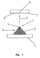
- Fig. 1 shows a schematic side view of a first embodiment of a field emission device according to the invention with an emission region 1 for 2 electrons cathode 3.
- the emission region 1 has an array of a plurality of individually positioned or positionable atoms 4.
- the arrangement of atoms 4 is arranged on a support 5, which may have, for example, glass, silicon, or carbon.
- the arrangement of atoms 4 essentially has the shape of a four-sided pyramid 6.
- a single atom 4 forms a tip of the emission region 1. From the tip, electrons 2, in the direction of an anode 7, are emitted.
- the anode 7 is formed as a thin film 8 and applied to a fluorescent material 9. Between the cathode 3 and the anode 7 acts a voltage which allows the field emission and thus the acceleration of the electrons 2 in the direction of the anode 7. The electrons incident on the fluorescent material 9 cause a light emission in the fluorescent material 9.
- the field emission device shown can be used in the manufacture of a TV screen.
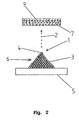
- Fig. 2 shows a schematic side view of a second embodiment of a field emission device according to the invention.
- the second embodiment is opposite to in Fig. 1 shown first embodiment, only the anode 7 is formed differently. Otherwise, the structure of the atoms 4 positioned on the carrier 5 corresponds to that in FIG Fig. 1 shown embodiment.
- the anode 7 is realized as an admixture in a fluorescent material 9.
- metallic particles may be mixed into the fluorescent material 9 to form, as it were, an anode 7 integrated in the fluorescent material 9.
Landscapes
- Engineering & Computer Science (AREA)
- Manufacturing & Machinery (AREA)
- Chemical & Material Sciences (AREA)
- Nanotechnology (AREA)
- Physics & Mathematics (AREA)
- Condensed Matter Physics & Semiconductors (AREA)
- General Physics & Mathematics (AREA)
- Crystallography & Structural Chemistry (AREA)
- Cathode-Ray Tubes And Fluorescent Screens For Display (AREA)
- Cold Cathode And The Manufacture (AREA)
- Gas-Filled Discharge Tubes (AREA)
Applications Claiming Priority (2)
| Application Number | Priority Date | Filing Date | Title |
|---|---|---|---|
| DE102006054206A DE102006054206A1 (de) | 2006-11-15 | 2006-11-15 | Feldemissionsvorrichtung |
| PCT/DE2007/002065 WO2008058527A2 (de) | 2006-11-15 | 2007-11-15 | Feldemissionsvorrichtung |
Publications (2)
| Publication Number | Publication Date |
|---|---|
| EP2092542A2 EP2092542A2 (de) | 2009-08-26 |
| EP2092542B1 true EP2092542B1 (de) | 2010-01-13 |
Family
ID=39311228
Family Applications (1)
| Application Number | Title | Priority Date | Filing Date |
|---|---|---|---|
| EP07846340A Not-in-force EP2092542B1 (de) | 2006-11-15 | 2007-11-15 | Feldemissionsvorrichtung |
Country Status (9)
| Country | Link |
|---|---|
| US (1) | US20100052511A1 (enExample) |
| EP (1) | EP2092542B1 (enExample) |
| JP (1) | JP2010509740A (enExample) |
| KR (1) | KR20090092770A (enExample) |
| CN (1) | CN101663724A (enExample) |
| AT (1) | ATE455358T1 (enExample) |
| CA (1) | CA2667653A1 (enExample) |
| DE (2) | DE102006054206A1 (enExample) |
| WO (1) | WO2008058527A2 (enExample) |
Families Citing this family (6)
| Publication number | Priority date | Publication date | Assignee | Title |
|---|---|---|---|---|
| US9224851B2 (en) | 2011-10-14 | 2015-12-29 | Diftek Lasers, Inc. | Planarized semiconductor particles positioned on a substrate |
| US9209019B2 (en) | 2013-09-05 | 2015-12-08 | Diftek Lasers, Inc. | Method and system for manufacturing a semi-conducting backplane |
| US9455307B2 (en) | 2011-10-14 | 2016-09-27 | Diftek Lasers, Inc. | Active matrix electro-optical device and method of making thereof |
| US10312310B2 (en) | 2016-01-19 | 2019-06-04 | Diftek Lasers, Inc. | OLED display and method of fabrication thereof |
| EP3933881A1 (en) | 2020-06-30 | 2022-01-05 | VEC Imaging GmbH & Co. KG | X-ray source with multiple grids |
| US12230468B2 (en) | 2022-06-30 | 2025-02-18 | Varex Imaging Corporation | X-ray system with field emitters and arc protection |
Family Cites Families (31)
| Publication number | Priority date | Publication date | Assignee | Title |
|---|---|---|---|---|
| JPS6276576A (ja) * | 1985-09-30 | 1987-04-08 | Toshiba Corp | 注入型発光素子 |
| US4818914A (en) * | 1987-07-17 | 1989-04-04 | Sri International | High efficiency lamp |
| GB2235819A (en) * | 1989-08-12 | 1991-03-13 | Cathodeon Ltd | Gas discharge display device |
| US5126574A (en) * | 1989-10-10 | 1992-06-30 | The United States Of America As Represented By The Secretary Of Commerce | Microtip-controlled nanostructure fabrication and multi-tipped field-emission tool for parallel-process nanostructure fabrication |
| JPH04315750A (ja) * | 1991-01-10 | 1992-11-06 | Nec Corp | 薄膜トランジスタ制御型蛍光表示パネル |
| US5515234A (en) * | 1993-06-30 | 1996-05-07 | Texas Instruments Incorporated | Antistatic protector and method |
| DE4405768A1 (de) * | 1994-02-23 | 1995-08-24 | Till Keesmann | Feldemissionskathodeneinrichtung und Verfahren zu ihrer Herstellung |
| USRE38561E1 (en) * | 1995-02-22 | 2004-08-03 | Till Keesmann | Field emission cathode |
| US5667724A (en) * | 1996-05-13 | 1997-09-16 | Motorola | Phosphor and method of making same |
| US5785873A (en) * | 1996-06-24 | 1998-07-28 | Industrial Technology Research Institute | Low cost field emission based print head and method of making |
| US5882533A (en) * | 1996-07-15 | 1999-03-16 | Industrial Technology Research Institute | Field emission based print head |
| EP0936651B1 (en) * | 1998-02-12 | 2004-08-11 | Canon Kabushiki Kaisha | Method for manufacturing electron emission element, electron source, and image forming apparatus |
| FR2789223B1 (fr) * | 1999-01-29 | 2001-03-23 | Univ Nantes | Corps de cathode ferroelectrique pour la production d'electrons |
| US6207578B1 (en) * | 1999-02-19 | 2001-03-27 | Micron Technology, Inc. | Methods of forming patterned constructions, methods of patterning semiconductive substrates, and methods of forming field emission displays |
| JP4010077B2 (ja) * | 1999-07-06 | 2007-11-21 | ソニー株式会社 | 冷陰極電界電子放出素子の製造方法及び冷陰極電界電子放出表示装置の製造方法 |
| US6342755B1 (en) * | 1999-08-11 | 2002-01-29 | Sony Corporation | Field emission cathodes having an emitting layer comprised of electron emitting particles and insulating particles |
| KR100480768B1 (ko) * | 1999-12-23 | 2005-04-06 | 삼성에스디아이 주식회사 | 전도성 발광물질을 이용한 저전압 구동용 적색 형광체 및그 제조방법 |
| JP2001236026A (ja) * | 2000-02-21 | 2001-08-31 | Ricoh Co Ltd | 表示用蛍光体、表示用蛍光体の製造方法、および該表示用蛍光体を使用した電界放出表示素子 |
| JP3906653B2 (ja) * | 2000-07-18 | 2007-04-18 | ソニー株式会社 | 画像表示装置及びその製造方法 |
| KR20020049630A (ko) * | 2000-12-19 | 2002-06-26 | 임지순 | 전계방출 에미터 |
| US7112366B2 (en) * | 2001-01-05 | 2006-09-26 | The Ohio State University | Chemical monolayer and micro-electronic junctions and devices containing same |
| JP2003115255A (ja) * | 2001-10-04 | 2003-04-18 | Kazuyuki Taji | 電界電子放出電極およびその製造方法 |
| KR20030060611A (ko) * | 2002-01-10 | 2003-07-16 | 삼성전자주식회사 | 보호막을 가지는 탄소나노튜브를 구비하는 전계방출소자 |
| US6852554B2 (en) * | 2002-02-27 | 2005-02-08 | Hewlett-Packard Development Company, L.P. | Emission layer formed by rapid thermal formation process |
| US6787792B2 (en) * | 2002-04-18 | 2004-09-07 | Hewlett-Packard Development Company, L.P. | Emitter with filled zeolite emission layer |
| JP2004241292A (ja) * | 2003-02-07 | 2004-08-26 | Sony Corp | 冷陰極電界電子放出表示装置 |
| CN1287413C (zh) * | 2003-03-26 | 2006-11-29 | 清华大学 | 一种场发射显示器 |
| KR100551229B1 (ko) * | 2003-06-26 | 2006-02-10 | 주식회사 디피아이 솔루션스 | 디스플레이용 유기 투명 전극의 제조방법 |
| US7201627B2 (en) * | 2003-07-31 | 2007-04-10 | Semiconductor Energy Laboratory, Co., Ltd. | Method for manufacturing ultrafine carbon fiber and field emission element |
| CN1333013C (zh) * | 2004-12-15 | 2007-08-22 | 中国科学院化学研究所 | 导电聚苯胺与碳纳米管复合的电磁屏蔽复合膜及其制法 |
| JP2006297549A (ja) * | 2005-04-21 | 2006-11-02 | Keio Gijuku | 金属ナノ粒子の配列蒸着方法及び金属ナノ粒子を用いたカーボンナノチューブの成長方法 |
-
2006
- 2006-11-15 DE DE102006054206A patent/DE102006054206A1/de not_active Ceased
-
2007
- 2007-11-15 EP EP07846340A patent/EP2092542B1/de not_active Not-in-force
- 2007-11-15 CN CN200780042058A patent/CN101663724A/zh active Pending
- 2007-11-15 WO PCT/DE2007/002065 patent/WO2008058527A2/de not_active Ceased
- 2007-11-15 DE DE502007002648T patent/DE502007002648D1/de active Active
- 2007-11-15 JP JP2009536600A patent/JP2010509740A/ja active Pending
- 2007-11-15 KR KR1020097009979A patent/KR20090092770A/ko not_active Withdrawn
- 2007-11-15 AT AT07846340T patent/ATE455358T1/de active
- 2007-11-15 CA CA002667653A patent/CA2667653A1/en not_active Abandoned
- 2007-11-15 US US12/514,765 patent/US20100052511A1/en not_active Abandoned
Also Published As
| Publication number | Publication date |
|---|---|
| CA2667653A1 (en) | 2008-05-22 |
| WO2008058527A2 (de) | 2008-05-22 |
| DE502007002648D1 (de) | 2010-03-04 |
| KR20090092770A (ko) | 2009-09-01 |
| US20100052511A1 (en) | 2010-03-04 |
| CN101663724A (zh) | 2010-03-03 |
| JP2010509740A (ja) | 2010-03-25 |
| EP2092542A2 (de) | 2009-08-26 |
| WO2008058527A3 (de) | 2008-10-16 |
| ATE455358T1 (de) | 2010-01-15 |
| DE102006054206A1 (de) | 2008-05-21 |
Similar Documents
| Publication | Publication Date | Title |
|---|---|---|
| DE60021778T2 (de) | Kohlenstofftinte, elektronenemittierendes Element, Verfahren zur Herstellung eines elektronenemittierenden Elements und Bildanzeigevorrichtung | |
| DE69607356T2 (de) | Feldelektronenemitterende materialen und vorrichtungen | |
| DE69816479T2 (de) | Feldemissionselektronenmaterialen und herstellungsverfahren | |
| DE69328977T2 (de) | Flache feldemissionskathode anwendende flache anzeigevorrichtung mit triodenstruktur | |
| EP0801805B1 (de) | Feldemissionskathodeneinrichtung und verfahren zur herstellung | |
| DE60014461T2 (de) | Feld Emissions Vorrichtung mit ausgerichteten und verkürzten Kohlenstoffnanoröhren und Herstellungsverfahren | |
| DE69318444T2 (de) | Elektronenquelle mit Mikropunktkathoden und Anzeigevorrichtung mit Kathodolumineszenz erregt durch Feldemission unter Anwendung dieser Quelle | |
| DE69503223T2 (de) | Feldemitter aus diamantfasern, diamantartigen fasern oder fasern aus glaskohlenstoff | |
| DE69619426T2 (de) | Bilderzeugungsgerät | |
| DE69019368T2 (de) | Feldeffektemissionsvorrichtung mit vorgeformten emittierenden elementen. | |
| DE69331749T2 (de) | Flacher bildschirm mit diodenstruktur | |
| EP2092542B1 (de) | Feldemissionsvorrichtung | |
| DE69727877T2 (de) | Elektronenröhre | |
| DE69413319T2 (de) | Bilderzeugungsgerät | |
| DE1957247C3 (de) | Bildröhre | |
| DE69730195T2 (de) | Bilderzeugungsgerät | |
| DE60037027T2 (de) | Elektronememittierende- und isolierende teilchen enthaltende feldemissions kathoden | |
| DE69529642T2 (de) | Vorrichtung zur Emission von Elektronen | |
| DE69530978T2 (de) | Begrenzung und Selbstvergleichmässigung von durch Mikrospitzen einer flachen Feldemissionsbildwiedergabevorrichtung fliessenden Kathodenströmen | |
| DE60122144T2 (de) | Gleichmässiger emissionsstrom für eine feldemissionsvorrichtung | |
| DE19724606C2 (de) | Feldemissions-Elektronenquelle für Flachbildschirme | |
| DE102006013223B4 (de) | Feldemissionsanzeigevorrichtung und Verfahren zum Betreiben derselben | |
| DE4416597B4 (de) | Verfahren und Vorrichtung zur Herstellung der Bildpunkt-Strahlungsquellen für flache Farb-Bildschirme | |
| DE602006000200T2 (de) | Elektronenemitter und Herstellungsverfahren | |
| DE69816604T2 (de) | Metall-kohlenstoff-sauerstoff-feldemissionsanordnungen |
Legal Events
| Date | Code | Title | Description |
|---|---|---|---|
| PUAI | Public reference made under article 153(3) epc to a published international application that has entered the european phase |
Free format text: ORIGINAL CODE: 0009012 |
|
| 17P | Request for examination filed |
Effective date: 20090312 |
|
| AK | Designated contracting states |
Kind code of ref document: A2 Designated state(s): AT BE BG CH CY CZ DE DK EE ES FI FR GB GR HU IE IS IT LI LT LU LV MC MT NL PL PT RO SE SI SK TR |
|
| GRAP | Despatch of communication of intention to grant a patent |
Free format text: ORIGINAL CODE: EPIDOSNIGR1 |
|
| DAX | Request for extension of the european patent (deleted) | ||
| GRAS | Grant fee paid |
Free format text: ORIGINAL CODE: EPIDOSNIGR3 |
|
| GRAA | (expected) grant |
Free format text: ORIGINAL CODE: 0009210 |
|
| AK | Designated contracting states |
Kind code of ref document: B1 Designated state(s): AT BE BG CH CY CZ DE DK EE ES FI FR GB GR HU IE IS IT LI LT LU LV MC MT NL PL PT RO SE SI SK TR |
|
| REG | Reference to a national code |
Ref country code: GB Ref legal event code: FG4D Free format text: NOT ENGLISH |
|
| REG | Reference to a national code |
Ref country code: CH Ref legal event code: EP |
|
| REG | Reference to a national code |
Ref country code: IE Ref legal event code: FG4D |
|
| REF | Corresponds to: |
Ref document number: 502007002648 Country of ref document: DE Date of ref document: 20100304 Kind code of ref document: P |
|
| REG | Reference to a national code |
Ref country code: NL Ref legal event code: T3 |
|
| LTIE | Lt: invalidation of european patent or patent extension |
Effective date: 20100113 |
|
| PG25 | Lapsed in a contracting state [announced via postgrant information from national office to epo] |
Ref country code: IS Free format text: LAPSE BECAUSE OF FAILURE TO SUBMIT A TRANSLATION OF THE DESCRIPTION OR TO PAY THE FEE WITHIN THE PRESCRIBED TIME-LIMIT Effective date: 20100513 Ref country code: ES Free format text: LAPSE BECAUSE OF FAILURE TO SUBMIT A TRANSLATION OF THE DESCRIPTION OR TO PAY THE FEE WITHIN THE PRESCRIBED TIME-LIMIT Effective date: 20100424 Ref country code: PT Free format text: LAPSE BECAUSE OF FAILURE TO SUBMIT A TRANSLATION OF THE DESCRIPTION OR TO PAY THE FEE WITHIN THE PRESCRIBED TIME-LIMIT Effective date: 20100513 Ref country code: LT Free format text: LAPSE BECAUSE OF FAILURE TO SUBMIT A TRANSLATION OF THE DESCRIPTION OR TO PAY THE FEE WITHIN THE PRESCRIBED TIME-LIMIT Effective date: 20100113 |
|
| REG | Reference to a national code |
Ref country code: IE Ref legal event code: FD4D |
|
| PG25 | Lapsed in a contracting state [announced via postgrant information from national office to epo] |
Ref country code: FI Free format text: LAPSE BECAUSE OF FAILURE TO SUBMIT A TRANSLATION OF THE DESCRIPTION OR TO PAY THE FEE WITHIN THE PRESCRIBED TIME-LIMIT Effective date: 20100113 Ref country code: LV Free format text: LAPSE BECAUSE OF FAILURE TO SUBMIT A TRANSLATION OF THE DESCRIPTION OR TO PAY THE FEE WITHIN THE PRESCRIBED TIME-LIMIT Effective date: 20100113 Ref country code: PL Free format text: LAPSE BECAUSE OF FAILURE TO SUBMIT A TRANSLATION OF THE DESCRIPTION OR TO PAY THE FEE WITHIN THE PRESCRIBED TIME-LIMIT Effective date: 20100113 Ref country code: SI Free format text: LAPSE BECAUSE OF FAILURE TO SUBMIT A TRANSLATION OF THE DESCRIPTION OR TO PAY THE FEE WITHIN THE PRESCRIBED TIME-LIMIT Effective date: 20100113 |
|
| PG25 | Lapsed in a contracting state [announced via postgrant information from national office to epo] |
Ref country code: RO Free format text: LAPSE BECAUSE OF FAILURE TO SUBMIT A TRANSLATION OF THE DESCRIPTION OR TO PAY THE FEE WITHIN THE PRESCRIBED TIME-LIMIT Effective date: 20100113 Ref country code: GR Free format text: LAPSE BECAUSE OF FAILURE TO SUBMIT A TRANSLATION OF THE DESCRIPTION OR TO PAY THE FEE WITHIN THE PRESCRIBED TIME-LIMIT Effective date: 20100414 Ref country code: EE Free format text: LAPSE BECAUSE OF FAILURE TO SUBMIT A TRANSLATION OF THE DESCRIPTION OR TO PAY THE FEE WITHIN THE PRESCRIBED TIME-LIMIT Effective date: 20100113 Ref country code: CY Free format text: LAPSE BECAUSE OF FAILURE TO SUBMIT A TRANSLATION OF THE DESCRIPTION OR TO PAY THE FEE WITHIN THE PRESCRIBED TIME-LIMIT Effective date: 20100113 Ref country code: IE Free format text: LAPSE BECAUSE OF FAILURE TO SUBMIT A TRANSLATION OF THE DESCRIPTION OR TO PAY THE FEE WITHIN THE PRESCRIBED TIME-LIMIT Effective date: 20100113 |
|
| PLBE | No opposition filed within time limit |
Free format text: ORIGINAL CODE: 0009261 |
|
| STAA | Information on the status of an ep patent application or granted ep patent |
Free format text: STATUS: NO OPPOSITION FILED WITHIN TIME LIMIT |
|
| PG25 | Lapsed in a contracting state [announced via postgrant information from national office to epo] |
Ref country code: SK Free format text: LAPSE BECAUSE OF FAILURE TO SUBMIT A TRANSLATION OF THE DESCRIPTION OR TO PAY THE FEE WITHIN THE PRESCRIBED TIME-LIMIT Effective date: 20100113 Ref country code: BG Free format text: LAPSE BECAUSE OF FAILURE TO SUBMIT A TRANSLATION OF THE DESCRIPTION OR TO PAY THE FEE WITHIN THE PRESCRIBED TIME-LIMIT Effective date: 20100413 Ref country code: CZ Free format text: LAPSE BECAUSE OF FAILURE TO SUBMIT A TRANSLATION OF THE DESCRIPTION OR TO PAY THE FEE WITHIN THE PRESCRIBED TIME-LIMIT Effective date: 20100113 |
|
| 26N | No opposition filed |
Effective date: 20101014 |
|
| PG25 | Lapsed in a contracting state [announced via postgrant information from national office to epo] |
Ref country code: DK Free format text: LAPSE BECAUSE OF FAILURE TO SUBMIT A TRANSLATION OF THE DESCRIPTION OR TO PAY THE FEE WITHIN THE PRESCRIBED TIME-LIMIT Effective date: 20100113 |
|
| PGFP | Annual fee paid to national office [announced via postgrant information from national office to epo] |
Ref country code: FR Payment date: 20101130 Year of fee payment: 4 Ref country code: NL Payment date: 20101123 Year of fee payment: 4 |
|
| PGFP | Annual fee paid to national office [announced via postgrant information from national office to epo] |
Ref country code: SE Payment date: 20101124 Year of fee payment: 4 |
|
| BERE | Be: lapsed |
Owner name: KEESMANN, TILL Effective date: 20101130 |
|
| PGFP | Annual fee paid to national office [announced via postgrant information from national office to epo] |
Ref country code: DE Payment date: 20110128 Year of fee payment: 4 |
|
| PG25 | Lapsed in a contracting state [announced via postgrant information from national office to epo] |
Ref country code: MC Free format text: LAPSE BECAUSE OF NON-PAYMENT OF DUE FEES Effective date: 20101130 |
|
| PG25 | Lapsed in a contracting state [announced via postgrant information from national office to epo] |
Ref country code: BE Free format text: LAPSE BECAUSE OF NON-PAYMENT OF DUE FEES Effective date: 20101130 |
|
| PG25 | Lapsed in a contracting state [announced via postgrant information from national office to epo] |
Ref country code: MT Free format text: LAPSE BECAUSE OF FAILURE TO SUBMIT A TRANSLATION OF THE DESCRIPTION OR TO PAY THE FEE WITHIN THE PRESCRIBED TIME-LIMIT Effective date: 20100113 Ref country code: IT Free format text: LAPSE BECAUSE OF NON-PAYMENT OF DUE FEES Effective date: 20101115 |
|
| PGFP | Annual fee paid to national office [announced via postgrant information from national office to epo] |
Ref country code: IT Payment date: 20101130 Year of fee payment: 4 |
|
| REG | Reference to a national code |
Ref country code: NL Ref legal event code: V1 Effective date: 20120601 |
|
| REG | Reference to a national code |
Ref country code: CH Ref legal event code: PL |
|
| REG | Reference to a national code |
Ref country code: SE Ref legal event code: EUG |
|
| GBPC | Gb: european patent ceased through non-payment of renewal fee |
Effective date: 20111115 |
|
| PG25 | Lapsed in a contracting state [announced via postgrant information from national office to epo] |
Ref country code: NL Free format text: LAPSE BECAUSE OF NON-PAYMENT OF DUE FEES Effective date: 20120601 Ref country code: LI Free format text: LAPSE BECAUSE OF NON-PAYMENT OF DUE FEES Effective date: 20111130 Ref country code: CH Free format text: LAPSE BECAUSE OF NON-PAYMENT OF DUE FEES Effective date: 20111130 |
|
| REG | Reference to a national code |
Ref country code: FR Ref legal event code: ST Effective date: 20120731 |
|
| PG25 | Lapsed in a contracting state [announced via postgrant information from national office to epo] |
Ref country code: IT Free format text: LAPSE BECAUSE OF NON-PAYMENT OF DUE FEES Effective date: 20111115 |
|
| REG | Reference to a national code |
Ref country code: CH Ref legal event code: AEN Free format text: DAS PATENT IST AUFGRUND DES WEITERBEHANDLUNGSANTRAGS VOM 30.08.2012 REAKTIVIERT WORDEN. ?? |
|
| REG | Reference to a national code |
Ref country code: DE Ref legal event code: R119 Ref document number: 502007002648 Country of ref document: DE Effective date: 20120601 |
|
| PG25 | Lapsed in a contracting state [announced via postgrant information from national office to epo] |
Ref country code: LU Free format text: LAPSE BECAUSE OF NON-PAYMENT OF DUE FEES Effective date: 20101115 Ref country code: HU Free format text: LAPSE BECAUSE OF FAILURE TO SUBMIT A TRANSLATION OF THE DESCRIPTION OR TO PAY THE FEE WITHIN THE PRESCRIBED TIME-LIMIT Effective date: 20100714 |
|
| PG25 | Lapsed in a contracting state [announced via postgrant information from national office to epo] |
Ref country code: GB Free format text: LAPSE BECAUSE OF NON-PAYMENT OF DUE FEES Effective date: 20111115 Ref country code: TR Free format text: LAPSE BECAUSE OF FAILURE TO SUBMIT A TRANSLATION OF THE DESCRIPTION OR TO PAY THE FEE WITHIN THE PRESCRIBED TIME-LIMIT Effective date: 20100113 Ref country code: SE Free format text: LAPSE BECAUSE OF NON-PAYMENT OF DUE FEES Effective date: 20111116 |
|
| PGRI | Patent reinstated in contracting state [announced from national office to epo] |
Ref country code: CH Effective date: 20120830 Ref country code: LI Effective date: 20120830 |
|
| PG25 | Lapsed in a contracting state [announced via postgrant information from national office to epo] |
Ref country code: FR Free format text: LAPSE BECAUSE OF NON-PAYMENT OF DUE FEES Effective date: 20111130 |
|
| PGFP | Annual fee paid to national office [announced via postgrant information from national office to epo] |
Ref country code: CH Payment date: 20121122 Year of fee payment: 6 |
|
| PG25 | Lapsed in a contracting state [announced via postgrant information from national office to epo] |
Ref country code: DE Free format text: LAPSE BECAUSE OF NON-PAYMENT OF DUE FEES Effective date: 20120601 |
|
| REG | Reference to a national code |
Ref country code: AT Ref legal event code: MM01 Ref document number: 455358 Country of ref document: AT Kind code of ref document: T Effective date: 20121130 |
|
| PG25 | Lapsed in a contracting state [announced via postgrant information from national office to epo] |
Ref country code: AT Free format text: LAPSE BECAUSE OF NON-PAYMENT OF DUE FEES Effective date: 20121130 |
|
| REG | Reference to a national code |
Ref country code: CH Ref legal event code: PL |
|
| PG25 | Lapsed in a contracting state [announced via postgrant information from national office to epo] |
Ref country code: LI Free format text: LAPSE BECAUSE OF NON-PAYMENT OF DUE FEES Effective date: 20131130 Ref country code: CH Free format text: LAPSE BECAUSE OF NON-PAYMENT OF DUE FEES Effective date: 20131130 |