EP2086030A2 - Piezoelektrische/elektrostriktive Keramik und Verfahren zu deren Herstellung - Google Patents
Piezoelektrische/elektrostriktive Keramik und Verfahren zu deren Herstellung Download PDFInfo
- Publication number
- EP2086030A2 EP2086030A2 EP20090250226 EP09250226A EP2086030A2 EP 2086030 A2 EP2086030 A2 EP 2086030A2 EP 20090250226 EP20090250226 EP 20090250226 EP 09250226 A EP09250226 A EP 09250226A EP 2086030 A2 EP2086030 A2 EP 2086030A2
- Authority
- EP
- European Patent Office
- Prior art keywords
- piezoelectric
- electrostrictive
- magnesium
- nickel
- film
- Prior art date
- Legal status (The legal status is an assumption and is not a legal conclusion. Google has not performed a legal analysis and makes no representation as to the accuracy of the status listed.)
- Granted
Links
Images




Classifications
-
- C—CHEMISTRY; METALLURGY
- C01—INORGANIC CHEMISTRY
- C01G—COMPOUNDS CONTAINING METALS NOT COVERED BY SUBCLASSES C01D OR C01F
- C01G33/00—Compounds of niobium
-
- C—CHEMISTRY; METALLURGY
- C01—INORGANIC CHEMISTRY
- C01G—COMPOUNDS CONTAINING METALS NOT COVERED BY SUBCLASSES C01D OR C01F
- C01G33/00—Compounds of niobium
- C01G33/006—Compounds containing niobium, with or without oxygen or hydrogen, and containing two or more other elements
-
- C—CHEMISTRY; METALLURGY
- C04—CEMENTS; CONCRETE; ARTIFICIAL STONE; CERAMICS; REFRACTORIES
- C04B—LIME, MAGNESIA; SLAG; CEMENTS; COMPOSITIONS THEREOF, e.g. MORTARS, CONCRETE OR LIKE BUILDING MATERIALS; ARTIFICIAL STONE; CERAMICS; REFRACTORIES; TREATMENT OF NATURAL STONE
- C04B35/00—Shaped ceramic products characterised by their composition; Ceramics compositions; Processing powders of inorganic compounds preparatory to the manufacturing of ceramic products
- C04B35/01—Shaped ceramic products characterised by their composition; Ceramics compositions; Processing powders of inorganic compounds preparatory to the manufacturing of ceramic products based on oxide ceramics
- C04B35/48—Shaped ceramic products characterised by their composition; Ceramics compositions; Processing powders of inorganic compounds preparatory to the manufacturing of ceramic products based on oxide ceramics based on zirconium or hafnium oxides, zirconates, zircon or hafnates
- C04B35/49—Shaped ceramic products characterised by their composition; Ceramics compositions; Processing powders of inorganic compounds preparatory to the manufacturing of ceramic products based on oxide ceramics based on zirconium or hafnium oxides, zirconates, zircon or hafnates containing also titanium oxides or titanates
- C04B35/491—Shaped ceramic products characterised by their composition; Ceramics compositions; Processing powders of inorganic compounds preparatory to the manufacturing of ceramic products based on oxide ceramics based on zirconium or hafnium oxides, zirconates, zircon or hafnates containing also titanium oxides or titanates based on lead zirconates and lead titanates, e.g. PZT
- C04B35/493—Shaped ceramic products characterised by their composition; Ceramics compositions; Processing powders of inorganic compounds preparatory to the manufacturing of ceramic products based on oxide ceramics based on zirconium or hafnium oxides, zirconates, zircon or hafnates containing also titanium oxides or titanates based on lead zirconates and lead titanates, e.g. PZT containing also other lead compounds
-
- C—CHEMISTRY; METALLURGY
- C04—CEMENTS; CONCRETE; ARTIFICIAL STONE; CERAMICS; REFRACTORIES
- C04B—LIME, MAGNESIA; SLAG; CEMENTS; COMPOSITIONS THEREOF, e.g. MORTARS, CONCRETE OR LIKE BUILDING MATERIALS; ARTIFICIAL STONE; CERAMICS; REFRACTORIES; TREATMENT OF NATURAL STONE
- C04B35/00—Shaped ceramic products characterised by their composition; Ceramics compositions; Processing powders of inorganic compounds preparatory to the manufacturing of ceramic products
- C04B35/01—Shaped ceramic products characterised by their composition; Ceramics compositions; Processing powders of inorganic compounds preparatory to the manufacturing of ceramic products based on oxide ceramics
- C04B35/495—Shaped ceramic products characterised by their composition; Ceramics compositions; Processing powders of inorganic compounds preparatory to the manufacturing of ceramic products based on oxide ceramics based on vanadium, niobium, tantalum, molybdenum or tungsten oxides or solid solutions thereof with other oxides, e.g. vanadates, niobates, tantalates, molybdates or tungstates
- C04B35/497—Shaped ceramic products characterised by their composition; Ceramics compositions; Processing powders of inorganic compounds preparatory to the manufacturing of ceramic products based on oxide ceramics based on vanadium, niobium, tantalum, molybdenum or tungsten oxides or solid solutions thereof with other oxides, e.g. vanadates, niobates, tantalates, molybdates or tungstates based on solid solutions with lead oxides
- C04B35/499—Shaped ceramic products characterised by their composition; Ceramics compositions; Processing powders of inorganic compounds preparatory to the manufacturing of ceramic products based on oxide ceramics based on vanadium, niobium, tantalum, molybdenum or tungsten oxides or solid solutions thereof with other oxides, e.g. vanadates, niobates, tantalates, molybdates or tungstates based on solid solutions with lead oxides containing also titanates
-
- C—CHEMISTRY; METALLURGY
- C04—CEMENTS; CONCRETE; ARTIFICIAL STONE; CERAMICS; REFRACTORIES
- C04B—LIME, MAGNESIA; SLAG; CEMENTS; COMPOSITIONS THEREOF, e.g. MORTARS, CONCRETE OR LIKE BUILDING MATERIALS; ARTIFICIAL STONE; CERAMICS; REFRACTORIES; TREATMENT OF NATURAL STONE
- C04B35/00—Shaped ceramic products characterised by their composition; Ceramics compositions; Processing powders of inorganic compounds preparatory to the manufacturing of ceramic products
- C04B35/622—Forming processes; Processing powders of inorganic compounds preparatory to the manufacturing of ceramic products
- C04B35/626—Preparing or treating the powders individually or as batches ; preparing or treating macroscopic reinforcing agents for ceramic products, e.g. fibres; mechanical aspects section B
- C04B35/62605—Treating the starting powders individually or as mixtures
- C04B35/62685—Treating the starting powders individually or as mixtures characterised by the order of addition of constituents or additives
-
- C—CHEMISTRY; METALLURGY
- C04—CEMENTS; CONCRETE; ARTIFICIAL STONE; CERAMICS; REFRACTORIES
- C04B—LIME, MAGNESIA; SLAG; CEMENTS; COMPOSITIONS THEREOF, e.g. MORTARS, CONCRETE OR LIKE BUILDING MATERIALS; ARTIFICIAL STONE; CERAMICS; REFRACTORIES; TREATMENT OF NATURAL STONE
- C04B35/00—Shaped ceramic products characterised by their composition; Ceramics compositions; Processing powders of inorganic compounds preparatory to the manufacturing of ceramic products
- C04B35/622—Forming processes; Processing powders of inorganic compounds preparatory to the manufacturing of ceramic products
- C04B35/626—Preparing or treating the powders individually or as batches ; preparing or treating macroscopic reinforcing agents for ceramic products, e.g. fibres; mechanical aspects section B
- C04B35/628—Coating the powders or the macroscopic reinforcing agents
- C04B35/62802—Powder coating materials
- C04B35/62805—Oxide ceramics
- C04B35/62826—Iron group metal oxides
-
- H—ELECTRICITY
- H10—SEMICONDUCTOR DEVICES; ELECTRIC SOLID-STATE DEVICES NOT OTHERWISE PROVIDED FOR
- H10N—ELECTRIC SOLID-STATE DEVICES NOT OTHERWISE PROVIDED FOR
- H10N30/00—Piezoelectric or electrostrictive devices
- H10N30/01—Manufacture or treatment
- H10N30/09—Forming piezoelectric or electrostrictive materials
- H10N30/093—Forming inorganic materials
- H10N30/097—Forming inorganic materials by sintering
-
- H—ELECTRICITY
- H10—SEMICONDUCTOR DEVICES; ELECTRIC SOLID-STATE DEVICES NOT OTHERWISE PROVIDED FOR
- H10N—ELECTRIC SOLID-STATE DEVICES NOT OTHERWISE PROVIDED FOR
- H10N30/00—Piezoelectric or electrostrictive devices
- H10N30/80—Constructional details
- H10N30/85—Piezoelectric or electrostrictive active materials
- H10N30/853—Ceramic compositions
- H10N30/8548—Lead-based oxides
-
- C—CHEMISTRY; METALLURGY
- C01—INORGANIC CHEMISTRY
- C01P—INDEXING SCHEME RELATING TO STRUCTURAL AND PHYSICAL ASPECTS OF SOLID INORGANIC COMPOUNDS
- C01P2002/00—Crystal-structural characteristics
- C01P2002/30—Three-dimensional structures
- C01P2002/34—Three-dimensional structures perovskite-type (ABO3)
-
- C—CHEMISTRY; METALLURGY
- C01—INORGANIC CHEMISTRY
- C01P—INDEXING SCHEME RELATING TO STRUCTURAL AND PHYSICAL ASPECTS OF SOLID INORGANIC COMPOUNDS
- C01P2004/00—Particle morphology
- C01P2004/60—Particles characterised by their size
- C01P2004/61—Micrometer sized, i.e. from 1-100 micrometer
-
- C—CHEMISTRY; METALLURGY
- C01—INORGANIC CHEMISTRY
- C01P—INDEXING SCHEME RELATING TO STRUCTURAL AND PHYSICAL ASPECTS OF SOLID INORGANIC COMPOUNDS
- C01P2006/00—Physical properties of inorganic compounds
- C01P2006/40—Electric properties
-
- C—CHEMISTRY; METALLURGY
- C04—CEMENTS; CONCRETE; ARTIFICIAL STONE; CERAMICS; REFRACTORIES
- C04B—LIME, MAGNESIA; SLAG; CEMENTS; COMPOSITIONS THEREOF, e.g. MORTARS, CONCRETE OR LIKE BUILDING MATERIALS; ARTIFICIAL STONE; CERAMICS; REFRACTORIES; TREATMENT OF NATURAL STONE
- C04B2235/00—Aspects relating to ceramic starting mixtures or sintered ceramic products
- C04B2235/02—Composition of constituents of the starting material or of secondary phases of the final product
- C04B2235/30—Constituents and secondary phases not being of a fibrous nature
- C04B2235/32—Metal oxides, mixed metal oxides, or oxide-forming salts thereof, e.g. carbonates, nitrates, (oxy)hydroxides, chlorides
- C04B2235/3205—Alkaline earth oxides or oxide forming salts thereof, e.g. beryllium oxide
- C04B2235/3206—Magnesium oxides or oxide-forming salts thereof
-
- C—CHEMISTRY; METALLURGY
- C04—CEMENTS; CONCRETE; ARTIFICIAL STONE; CERAMICS; REFRACTORIES
- C04B—LIME, MAGNESIA; SLAG; CEMENTS; COMPOSITIONS THEREOF, e.g. MORTARS, CONCRETE OR LIKE BUILDING MATERIALS; ARTIFICIAL STONE; CERAMICS; REFRACTORIES; TREATMENT OF NATURAL STONE
- C04B2235/00—Aspects relating to ceramic starting mixtures or sintered ceramic products
- C04B2235/02—Composition of constituents of the starting material or of secondary phases of the final product
- C04B2235/30—Constituents and secondary phases not being of a fibrous nature
- C04B2235/32—Metal oxides, mixed metal oxides, or oxide-forming salts thereof, e.g. carbonates, nitrates, (oxy)hydroxides, chlorides
- C04B2235/3231—Refractory metal oxides, their mixed metal oxides, or oxide-forming salts thereof
- C04B2235/3244—Zirconium oxides, zirconates, hafnium oxides, hafnates, or oxide-forming salts thereof
- C04B2235/3248—Zirconates or hafnates, e.g. zircon
- C04B2235/3249—Zirconates or hafnates, e.g. zircon containing also titanium oxide or titanates, e.g. lead zirconate titanate (PZT)
-
- C—CHEMISTRY; METALLURGY
- C04—CEMENTS; CONCRETE; ARTIFICIAL STONE; CERAMICS; REFRACTORIES
- C04B—LIME, MAGNESIA; SLAG; CEMENTS; COMPOSITIONS THEREOF, e.g. MORTARS, CONCRETE OR LIKE BUILDING MATERIALS; ARTIFICIAL STONE; CERAMICS; REFRACTORIES; TREATMENT OF NATURAL STONE
- C04B2235/00—Aspects relating to ceramic starting mixtures or sintered ceramic products
- C04B2235/02—Composition of constituents of the starting material or of secondary phases of the final product
- C04B2235/30—Constituents and secondary phases not being of a fibrous nature
- C04B2235/32—Metal oxides, mixed metal oxides, or oxide-forming salts thereof, e.g. carbonates, nitrates, (oxy)hydroxides, chlorides
- C04B2235/3231—Refractory metal oxides, their mixed metal oxides, or oxide-forming salts thereof
- C04B2235/3251—Niobium oxides, niobates, tantalum oxides, tantalates, or oxide-forming salts thereof
- C04B2235/3255—Niobates or tantalates, e.g. silver niobate
-
- C—CHEMISTRY; METALLURGY
- C04—CEMENTS; CONCRETE; ARTIFICIAL STONE; CERAMICS; REFRACTORIES
- C04B—LIME, MAGNESIA; SLAG; CEMENTS; COMPOSITIONS THEREOF, e.g. MORTARS, CONCRETE OR LIKE BUILDING MATERIALS; ARTIFICIAL STONE; CERAMICS; REFRACTORIES; TREATMENT OF NATURAL STONE
- C04B2235/00—Aspects relating to ceramic starting mixtures or sintered ceramic products
- C04B2235/02—Composition of constituents of the starting material or of secondary phases of the final product
- C04B2235/30—Constituents and secondary phases not being of a fibrous nature
- C04B2235/32—Metal oxides, mixed metal oxides, or oxide-forming salts thereof, e.g. carbonates, nitrates, (oxy)hydroxides, chlorides
- C04B2235/327—Iron group oxides, their mixed metal oxides, or oxide-forming salts thereof
- C04B2235/3279—Nickel oxides, nickalates, or oxide-forming salts thereof
-
- C—CHEMISTRY; METALLURGY
- C04—CEMENTS; CONCRETE; ARTIFICIAL STONE; CERAMICS; REFRACTORIES
- C04B—LIME, MAGNESIA; SLAG; CEMENTS; COMPOSITIONS THEREOF, e.g. MORTARS, CONCRETE OR LIKE BUILDING MATERIALS; ARTIFICIAL STONE; CERAMICS; REFRACTORIES; TREATMENT OF NATURAL STONE
- C04B2235/00—Aspects relating to ceramic starting mixtures or sintered ceramic products
- C04B2235/70—Aspects relating to sintered or melt-casted ceramic products
- C04B2235/74—Physical characteristics
- C04B2235/76—Crystal structural characteristics, e.g. symmetry
- C04B2235/768—Perovskite structure ABO3
-
- H—ELECTRICITY
- H10—SEMICONDUCTOR DEVICES; ELECTRIC SOLID-STATE DEVICES NOT OTHERWISE PROVIDED FOR
- H10N—ELECTRIC SOLID-STATE DEVICES NOT OTHERWISE PROVIDED FOR
- H10N30/00—Piezoelectric or electrostrictive devices
- H10N30/01—Manufacture or treatment
- H10N30/05—Manufacture of multilayered piezoelectric or electrostrictive devices, or parts thereof, e.g. by stacking piezoelectric bodies and electrodes
- H10N30/053—Manufacture of multilayered piezoelectric or electrostrictive devices, or parts thereof, e.g. by stacking piezoelectric bodies and electrodes by integrally sintering piezoelectric or electrostrictive bodies and electrodes
-
- H—ELECTRICITY
- H10—SEMICONDUCTOR DEVICES; ELECTRIC SOLID-STATE DEVICES NOT OTHERWISE PROVIDED FOR
- H10N—ELECTRIC SOLID-STATE DEVICES NOT OTHERWISE PROVIDED FOR
- H10N30/00—Piezoelectric or electrostrictive devices
- H10N30/20—Piezoelectric or electrostrictive devices with electrical input and mechanical output, e.g. functioning as actuators or vibrators
- H10N30/204—Piezoelectric or electrostrictive devices with electrical input and mechanical output, e.g. functioning as actuators or vibrators using bending displacement, e.g. unimorph, bimorph or multimorph cantilever or membrane benders
- H10N30/2047—Membrane type
-
- H—ELECTRICITY
- H10—SEMICONDUCTOR DEVICES; ELECTRIC SOLID-STATE DEVICES NOT OTHERWISE PROVIDED FOR
- H10N—ELECTRIC SOLID-STATE DEVICES NOT OTHERWISE PROVIDED FOR
- H10N30/00—Piezoelectric or electrostrictive devices
- H10N30/50—Piezoelectric or electrostrictive devices having a stacked or multilayer structure
Definitions
- the present invention relates to piezoelectric/electrostrictive ceramics that exhibit only a small change in properties after polarization, high insulating properties, and narrow variations in durability, and to a process for producing such piezoelectric/electrostrictive ceramics.
- Piezoelectric/electrostrictive actuators have the advantage of precise displacement control of the order of submicrons.
- piezoelectric/electrostrictive actuators employing a sintered piezoelectric/electrostrictive ceramic body as a piezoelectric/electrostrictive body have the advantages of, in addition to precise displacement control, high electromechanical conversion efficiency, high generative power, fast response speed, great durability, and low power consumption. With these advantages, they are used for equipment such as inkjet printer heads, diesel engine injectors, hydraulic servo valves, VTR heads, and pixels in piezoelectric ceramic displays.
- Patent document 1 also discloses that nickel has a concentration gradient in the direction along the thickness of a piezoelectric/electrostrictive film.
- the piezoelectric/electrostrictive ceramic includes a perovskite oxide containing lead as an A-site component and magnesium, nickel, niobium, titanium, and zirconium as B-site components. Crystal grains in the piezoelectric/electrostrictive ceramic have a core/shell construction with a shell portion having a higher concentration of nickel than a core portion and with the core portion having a higher concentration of magnesium than the shell portion.
- This piezoelectric/electrostrictive ceramic exhibits only a small change in properties after polarization, high insulating properties, and narrow variations in durability.
- a process for producing a piezoelectric/electrostrictive ceramic includes the following steps: (a) initiating a reaction between raw materials for first elements selected from among B-site components to form an intermediate, the first elements including magnesium and niobium and not including nickel; and (b) initiating a reaction between the intermediate synthesized in said step (a) and a raw material for a second element selected from among A-site and B-site components, the second element including nickel and not including magnesium.
- the steps (a) and (b) produce a piezoelectric/electrostrictive ceramic that includes a perovskite oxide containing lead as an A-site component and magnesium, nickel, niobium, zirconium, and titanium as B-site components.
- This process produces a piezoelectric/electrostrictive ceramic that exhibits only a small change in properties after polarization, high insulating properties, and narrow variations in durability.
- Fig. 1 is a diagrammatic illustration of the principal part of a piezoelectric/electrostrictive element 1 according to a first preferred embodiment of the invention, showing the piezoelectric/electrostrictive element 1 in cross section.
- the piezoelectric/electrostrictive element 1 in Fig. 1 is an actuator adopted in an inkjet printer head. This, however, is not meant to limit the application of the invention to only piezoelectric/electrostrictive elements for inkjet printer heads.
- the present invention may be applicable to, for example, various kinds of actuators or sensors.
- the piezoelectric/electrostrictive element 1 has a laminated structure in which an electrode film 110, a piezoelectric/electrostrictive film 112, another electrode film 114, another piezoelectric/electrostrictive film 116, and another electrode film 118 are laminated in order of mention on a thin portion 104 of a substrate 102.
- the present invention is also applicable to the cases where two or more layers of electrode film are within the laminated body 108 or where no electrode film is within the laminated body 108. While in the case of Fig. 1 the laminated body 108 is formed directly on the substrate 102, the laminated body 108 may indirectly be formed on the substrate 102 with an inert layer therebetween. Alternatively, a plurality of piezoelectric/electrostrictive elements 1 may be arranged at regular intervals into an integral unit.
- a drive signal is applied between the electrode films 110, 118 as external electrodes and the electrode film 114 as an internal electrode so that an electric field is applied to the piezoelectric/electrostrictive films 112 and 116 to induce flexural oscillations of the thin portion 104 and the laminated body 108.
- a region 182 in which such flexural oscillations are excited is referred to as a "flexural oscillation region.”
- the substrate 102 supports the laminated body 108.
- the substrate 102 is a sintered ceramic body produced by firing laminated sheet compacts of a ceramic powder.
- the substrate 102 is made of an insulating material.
- the insulating material should preferably be zirconium oxide (ZrO 2 ) with the addition of a stabilizer, such as calcium oxide (CaO), magnesium oxide (MgO), yttrium oxide (Y 2 O 3 ), ytterbium oxide (Yb 2 O 3 ), or cerium oxide (Ce 2 O 3 ); that is, it should preferably be stabilized or partly stabilized zirconia.
- a stabilizer such as calcium oxide (CaO), magnesium oxide (MgO), yttrium oxide (Y 2 O 3 ), ytterbium oxide (Yb 2 O 3 ), or cerium oxide (Ce 2 O 3 ); that is, it should preferably be stabilized or partly stabilized zirconia.
- the substrate 102 has a cavity structure with the central thin portion 104 surrounded and supported by a peripheral thick portion 106.
- the thin portion 104 should preferably have a plate thickness of 0.5 to 15 ⁇ m , more preferably, 0.5 to 10 ⁇ m . This is because the plate thickness below this range tends to cause damage to the thin portion 104, while the plate thickness above this range tends to reduce the displacement of the piezoelectric/electrostrictive element 1.
- the piezoelectric/electrostrictive films 112 and 116 are sintered ceramics body produced by firing a film compact of a ceramic powder.
- the piezoelectric/electrostrictive films 112 and 116 are made of a piezoelectric/electrostrictive material.
- the piezoelectric/electrostrictive films 112 and 116 should preferably include a perovskite oxide containing lead (Pb) as an A-site component and magnesium (Mg), nickel (Ni), niobium (Nb), titanium (Ti), and zirconium (Zr) as B-site components.
- variable x is defined as 0.95 ⁇ x ⁇ 1.10 because the variable x below this range tends to degrade sintering properties of the piezoelectric/electrostrictive ceramics, while the variable x above this range tends to increase segregating elements such as lead oxide (PbO), resulting in degraded insulating and moisture-resistant properties of the piezoelectric/electrostrictive ceramics.
- PbO lead oxide
- variable y is defined as 0.05 ⁇ y ⁇ 0.50 because the variable y outside this range tends to result in lower electric-field-induced strains of the piezoelectric/electrostrictive ceramics.
- variable z is defined as 0.90 ⁇ z ⁇ 1.10 because the variable z below this range tends to cause an excessive increase of donor components, resulting in degraded sintering properties of the piezoelectric/electrostrictive ceramics, while the variable z above this range tends to cause an excessive increase of acceptor components, resulting in an excessive progress of the grain growth of the piezoelectric/electrostrictive ceramics.
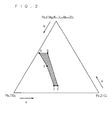
- the ratio of composition ( a , b , c ) is made to fall within the range defined by the five points, namely A(0.550, 0.425, 0.025), B(0.550, 0.325, 0.125), C(0.100, 0.425, 0.475), D(0.100, 0.475, 0.425), and E(0.375, 0.425, 0.200), in the ternary diagram in Fig. 2 because the ratio of composition ( a , b , c ) outside this range tends to cause the piezoelectric/electrostrictive ceramics to have a composition apart from the Morphotropic phase boundary, resulting in degraded piezoelectric/electrostrictive properties of the piezoelectric/electrostrictive ceramics.
- a part of lead forming an A-site may be substituted with alkaline-earth metal elements such as calcium (Ca), strontium (Sr), or barium (Ba) or with rare-earth elements such as lanthanum (La) or neodymium (Nd).
- the piezoelectric/electrostrictive ceramics may further include at least one or more oxides selected from the group consisting of cerium oxide (Ce 2 O 3 ), yttrium oxide (Y 2 O 3 ), aluminum oxide (Al 2 O 3 ), nickel oxide (NiO), niobium oxide (Nb 2 O 5 ), and the like.
- variable x is defined as 0.95 ⁇ x ⁇ 1.10 because the variable x below this range tends to degrade sintering properties of the piezoelectric/electrostrictive ceramics, while the variable x above this range tends to increase segregating elements such as lead oxide, resulting in degraded insulating and moisture-resistant properties of the piezoelectric/electrostrictive ceramics.
- variable y is defined as 0.90 ⁇ y ⁇ 1.10 because the variable y below this range tends to cause an excessive increase of donor components, resulting in degraded sintering properties of the piezoelectric/electrostrictive ceramics, while the variable y above this range tends to cause an excessive increase of acceptor components, resulting in an excessive progress of the grain growth of the piezoelectric/electrostrictive ceramics.
- composition ( a , b , c ) is made to fall within the range defined by the six points, namely F(0.550, 0.425, 0.025), G(0.550, 0.325, 0.125), H(0.375, 0.325, 0.300), I(0.050, 0.425, 0.525), J(0.050, 0.525, 0.425), and K(0.375, 0.425, 0.200), in the ternary diagram in Fig.
- the piezoelectric/electrostrictive films 112 and 116 have such a film thickness distribution that the film thickness increases continuously from the central portion of the flexural oscillation region 182, the central portion being the antinode of the primary flexural mode, toward the edge of the flexural oscillation region 182, the edge being the node of the primary flexural mode.
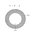
- Crystal grains in the piezoelectric/electrostrictive films 112 and 116 should preferably have a core/shell structure with the shell portion 124 having a higher concentration of nickel than the core portion 122 and with the core portion 122 having a higher concentration of magnesium than the shell portion 124 as schematically illustrated in Fig. 4 .
- the electrode films 110, 114, and 118 are made of a conductive material.
- the conductive material for the electrode films 110 and 114 should preferably be platinum (Pt) or palladium (Pd), or an alloy consisting primarily of Pt or Pd. It is, however, to be noted that, if the piezoelectric/electrostrictive films 112 and 116 can be sintered together, the electrode films 110 and 114 may be made of any other conductive material.
- the conductive material for the electrode film 118 should preferably be gold (Au) or an alloy consisting primarily of Au.
- the electrode films 110 and 114 are opposed to each other with the piezoelectric/electrostrictive film 112 therebetween, and the electrode films 114 and 118 are opposed to each other with the piezoelectric/electrostrictive film 116 therebetween.
- the electrode film 110 and 118 are electrically connected to each other. This configuration allows the piezoelectric/electrostrictive films 112 and 116 to expand and contract upon the application of a drive signal between the electrode films 110, 118 as external electrodes and the electrode film 114 as an internal electrode, thus allowing flexural oscillations in the flexural oscillation region 182.
- Fig. 5 is a flowchart for explaining a process for producing the piezoelectric/electrostrictive element 1.
- the production of the piezoelectric/electrostrictive element 1 firstly starts with the preparation of the substrate 102 (step S101).
- the laminated body 108 is formed on the thin portion 104 of the substrate 102 (steps S 102 to S 109).
- a conductor paste which is a kneaded product of a conductive material powder, an organic solvent, a dispersant, and a binder is applied by screen printing to the upper surface of the thin portion 104 (step S102), and the resulting coating film is fired integrally with the substrate 102 (step S103). This produces the electrode film 110 united with the substrate 102.
- a piezoelectric/electrostrictive paste which is a kneaded product of piezoelectric/electrostrictive material powder, an organic solvent, a dispersant, and a binder; a conductor paste; and another piezoelectric/electrostrictive paste are applied sequentially by screen printing to the upper surface of the electrode film 110 (steps S104, S105, and S106), and the resulting coating film is fired integrally with the substrate 102 and the electrode film 110 (step S107).
- a conductor paste is applied by screen printing to the upper surface of the piezoelectric/electrostrictive film 116 (step S108), and the resultant coating film is fired integrally with the substrate 102, the electrode film 110, the piezoelectric/electrostrictive film 112, the electrode film 114, and the piezoelectric/electrostrictive film 116 (step S109).
- a piezoelectric/electrostrictive material powder should preferably be synthesized firstly by the reaction of powders of raw materials for first elements selected from among B-site components, the first elements including magnesium and niobium and not including nickel, to form an intermediate powder and then by the reaction of the intermediate powder with powders of raw materials for second elements selected from among A-site and B-site components, the second elements including nickel and not including magnesium.
- the raw materials should preferably be oxides, but it may be compounds, such as hydroxides, carbonates, or tartrates, that turn into oxides during calcination.
- the synthesis of a piezoelectric/electrostrictive material powder firstly starts with weighing of raw materials for the first elements selected from among the B-site components, the first elements including magnesium and niobium and not including nickel, so as to form a desired intermediate to be synthesized (step S121).
- the weighed raw materials for the first elements are then mixed with the addition of a dispersion medium in a ball mill, a bead mill, an oscillating mill, or other mills, and the dispersion medium is removed by evaporation drying, filteration, or other techniques from the resulting slurry of a mixture of the raw materials for the first elements (step S122).
- the mixture of the raw materials for the first elements is calcinated to initiate a reaction of the raw materials for the first elements, thereby synthesizing an intermediate (step S123).
- the synthesized intermediate powder may then be either grinded or classified to control a particle size distribution of the intermediate powder. It is also preferable that the synthesis of the intermediate be speeded up by performing calcination two or more times.
- the most typical case is to synthesize a columbite compound (MgNb 2 O 6 ) as an intermediate from magnesium and niobium as the first elements; however, it may also be possible to synthesize as an intermediate any other compound of magnesium and niobium oxides than a columbite compound, or a solid solution of magnesium and niobium oxides (e.g., Mg 4 Nb 2 O 9 or a solid solution of MgNb 2 O 6 and Ng 5 Nb 4 O 15 ) As another alternative, the first elements may further include other B-site components except nickel.
- the first elements may include titanium and zirconium, and a compound or solid solution of magnesium, niobium, titanium, and zirconium oxides (i.e., a MgO-Nb 2 O 5 -TiO 2 -ZrO 2 compound or solid solution) may be synthesized as an intermediate.
- a compound or solid solution of magnesium, niobium, titanium, and zirconium oxides i.e., a MgO-Nb 2 O 5 -TiO 2 -ZrO 2 compound or solid solution
- step S124 the intermediate and the raw materials for second elements selected from among A-site and B-site components, the second elements including nickel and not including magnesium, are weighed so as to form a desired piezoelectric/electrostrictive material to be synthesized.
- the weighed raw materials for the second elements and intermediate are then mixed with the addition of a dispersion medium in a ball mill, a bead mill, an oscillating mill, or other mills, and the dispersion medium is removed by evaporation drying, filteration, or other techniques from the resulting slurry of the mixture of the raw materials for the second elements and the intermediate (step S125).
- the mixture of the raw materials for the second elements and the intermediate is calcinated to initiate a reaction of the intermediate and the raw materials for the second elements, thereby synthesizing a target piezoelectric/electrostrictive material (step S126).
- the synthesized piezoelectric/electrostrictive material powder may then be either grinded or classified to control a particle size distribution of the piezoelectric/electrostrictive material powder. It is also preferable that the synthesis of the piezoelectric/electrostrictive material be progressed by performing calcination two or more times.
- This process for synthesizing a piezoelectric/electrostrictive material powder firstly synthesizes an intermediate containing magnesium and niobium and then synthesizes a target piezoelectric/electrostrictive material. This prevents a third component introduced in PZT (titanium lead zirconate) from having a varying composition among Pb(Mg 1/3 Nb 2/3 )O 3 , Pb(Ni 1/3 Nb 2/3 )O 3 , and Pb ⁇ (Mg, Nb) 1/3 Nb 2/3 ⁇ O 3 , thus reducing variations in the durability of the piezoelectric/electrostrictive films.
- PZT titanium lead zirconate
- the first is the synthesis of Pb(Mg 1/3 Nb 2/3 )O 3
- the second is the reaction of Pb(Mg 1/3 Nb 2/3 )O 3 with NiO
- the third is the substitution of Mg with Ni starting from the surface of the Pb(Mg 1/3 Nb 2/3 )O 3 particles.
- Pb(Mg 1/3 Nb 2/3 )O 3 , Pb(Ni 1/3 Nb 2/3 )O 3 , and Pb ⁇ (Mg, Nb) 1/3 Nb 2/3 ⁇ O 3 are all synthesized so that variations will occur in durability depending on the composition.
- the amounts of lead and nickel be increased at the time of weighing in consideration of the amount of evaporation, because a target composition may not be obtained due to evaporation of lead and nickel during firing. Increasing the amount of nickel also brings about the effect of accelerating the grain growth during firing.
- Fig. 7 is a diagrammatic illustration of the principal part of a piezoelectric/electrostrictive element 2 according to a second preferred embodiment of the invention, showing the piezoelectric/electrostrictive element 2 in cross section.
- the piezoelectric/electrostrictive element 2 in Fig. 7 is an actuator adopted in an inkjet printer head.
- the piezoelectric/electrostrictive element 2 has a laminated structure in which an electrode film 210, a piezoelectric/electrostrictive film 212, another electrode film 214, another piezoelectric/electrostrictive film 216, and another electrode film 218 are laminated in order of mention on a thin portion 204 of a substrate 202.
- the substrate 202, the electrode film 210, the piezoelectric/electrostrictive film 212, the electrode film 214, the piezoelectric/electrostrictive film 216, and the electrode film 218 of the piezoelectric/electrostrictive element 2 are configured in a similar way to the substrate 102, the electrode film 110, the piezoelectric/electrostrictive film 112, the electrode film 114, the piezoelectric/electrostrictive film 116, and the electrode film 118 of the piezoelectric/electrostrictive element 1, except in that the piezoelectric/electrostrictive films 212 and 216 have a different film thickness distribution from the piezoelectric/electrostrictive films 112 and 116.
- the piezoelectric/electrostrictive films 212 and 216 have such a film thickness distribution that the film thickness decreases continuously from the central portion of a flexural oscillation region 282, the central portion being the antinode of the primary flexural mode, toward the edge of the flexural oscillation region 282, the edge being the node of the primary flexural mode, which distribution is the reverse of that of the piezoelectric/electrostrictive films 112 and 116.
- piezoelectric/electrostrictive films 212 and 236 formed of crystal grains having the core/shell structure in Fig. 4 are also produced by filing a film compact of a piezoelectric/electrostrictive material powder as described in the first preferred embodiment.
- the piezoelectric/electrostrictive films 212 and 236 can thus exhibit a small change in properties, high insulating properties, and narrow variations in durability.
- EXAMPLE 1 a magnesium carbonate (MgCO 3 ) powder and a niobium oxide (Nb 2 O 5 ) powder, which are raw materials for magnesium and niobium, were weighed so as to obtain a Mg to Nb molar ratio of 1:2.
- MgCO 3 magnesium carbonate
- Nb 2 O 5 niobium oxide
- the weighed magnesium carbonate and niobium oxide were then mixed with the addition of water as a dispersion medium in a ball mill, and the resulting slurry of a mixture of magnesium carbonate and niobium oxide was dried by evaporation in a dryer to be dehydrated.
- the mixture of magnesium carbonate and niobium oxide was then placed in an alumina (Al 2 O 3 ) sagger and was calcined in an electric furnace at 950° C to synthesize a columbite compound (MgNb 2 O 6 ) powder.
- the synthesized columbite compound was then added with water as a dispersion medium and was grinded in the ball mill. The resulting slurry of the grinded columbite compound was dried by evaporation in the dryer to be dehydrated.
- the grinded columbite compound was placed in the alumina sagger and was calcined at 950° C in the electric furnace to progress the synthesis of the columbite compound.
- the columbite compound was then added with water as a dispersion medium and was grinded in the ball mill.
- the resulting slurry of the grinded columbite compound was dried by evaporation in the dryer to be dehydrated.
- a lead oxide (PbO) powder, a nickel oxide (NiO) powder, a niobium oxide (Nb 2 O 5 ) powder, a titanium oxide (TiO 2 ) powder, and a zirconium oxide (ZrO 2 ) powder which are raw materials for lead, nickel, niobium, titanium, and zirconium; and the synthesized columbite compound powder were weighed to obtain a piezoelectric/electrostrictive material having a composition represented by the following formula: 0.20 Pb ⁇ ( Mg 0.87 Ni 0.13 ) 1/3 Nb 2/3 ⁇ O 3 - 0.43 Pb x TiO 3 -0.37 Pb x ZrO 3 .
- the weighed columbite compound, lead oxide, nickel oxide, niobium oxide, titanium oxide, and zirconium oxide were then mixed with the addition of water as a dispersion medium in the ball mill.
- the resulting slurry of a mixture of the columbite compound, lead oxide, nickel oxide, niobium oxide, titanium oxide, and zirconium oxide was dried by evaporation in the drier to be dehydrated.
- the mixture of the columbite compound, lead oxide, nickel oxide, niobium oxide, titanium oxide, and zirconium oxide was placed in a magnesia (MgO) sagger and was calcined in the electric furnace at 950 ° C to synthesize a piezoelectric/electrostrictive material powder.
- MgO magnesia
- the synthesized piezoelectric/electrostrictive material was added with water as a dispersion medium and was grinded in the ball mill, and the resulting slurry of the grinded piezoelectric/electrostrictive material was dried by evaporation in the drier to be dehydrated.
- the substrate 102 of yttria-stabilized zirconia is prepared.
- the thin portion 104 of the substrate 102 is rectangular in plane shape, having a size of 1.6 mm by 1.1 mm and a thickness of 6 ⁇ m .
- a platinum paste which was a kneaded product of a platinum powder, an organic solvent, a dispersant, and a binder was applied by screen printing on the flat upper surface of the thin portion 104 to form a coating film of the platinum paste.
- the coating film of the platinum paste is rectangular in plan shape in plane shape, having a size of 1.2 mm by 0.8 mm and a thickness of 3 ⁇ m .
- the coating of the platinum paste was then placed and fired in the electric furnace at 1250° C for two hours.
- a piezoelectric/electrostrictive paste which was a kneaded product of the synthesized piezoelectric/electrostrictive material powder, an organic solvent, a dispersant, and a binder; a platinum paste; and another piezoelectric/electrostrictive paste were applied sequentially by screen printing to the upper surface of the electrode film 110 to form a coating film of the piezoelectric/electrostrictive paste, a coating film of the platinum paste, and another coating film of the piezoelectric/electrostrictive paste.
- the coating films of the piezoelectric/electrostrictive pastes are rectangular in plan shape, having a size of 1.3 mm by 0.9 mm and a thickness of 11 ⁇ m .
- the platinum paste used contains 0.6 parts by weight of cerium oxide to 100 parts by weight of the platinum powder and 20 parts by volume of the piezoelectric/electrostrictive material powder to 100 parts by volume of the platinum powder.
- the coating of the platinum paste has a thickness of 2 ⁇ m .
- the coating film of the one piezoelectric/electrostrictive paste, the coating film of the platinum paste, and the coating film of the other piezoelectric/electrostrictive paste were then packed in the magnesia sagger and was placed and fired in the electric furnace at 1275° C for two hours.
- the piezoelectric/electrostrictive films 112 and 116 after firing have a thickness of 7 ⁇ m .
- a gold paste which was a kneaded product of a gold powder, an organic solvent, a dispersant, and a binder was applied by screen printing to the upper surface of the piezoelectric/electrostrictive film 112 to form a coating film of the gold paste.
- the coating film of the gold paste is rectangular in plane shape, having a size of 1.2 mm by 0.8 mm and a thickness of 0.5 ⁇ m .
- the coating film of the gold paste was then fired in the electric furnace at 800° C for two hours.
- Fig. 8 plots the electrical resistance value (the vertical axis) after the durability test for each of the 20 piezoelectric/electrostrictive elements 1 (the horizontal axis) according to EXAMPLE 1. As shown in Fig. 8 , in EXAMPLE 1, three out of the 20 piezoelectric/electrostrictive elements 1 have electrical resistance values less than 10 6 ⁇ .
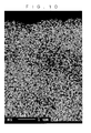
- the cross sections of the piezoelectric/electrostrictive elements 1 were mirror-polished, and the magnesium and nickel distributions in the cross sections of the piezoelectric/electrostrictive elements 1 were examined through EPMA (Electron Probe Micro Analysis). The results were shown in Figs. 9 and 10 .
- the white part represents a high element concentration.
- crystal grains in the piezoelectric/electrostrictive films 112 and 116 have a core/shell structure in which the shell portion closer to the grain boundary has a higher concentration of nickel than the core portion further away from the grain boundary, while the core portion further away from the grain boundary has a higher concentration of magnesium than the shell portion closer to the grain boundary.
- the weighed lead oxide powder, magnesium carbonate powder, nickel oxide powder, niobium oxide powder, titanium oxide powder, and zirconium oxide powder were mixed with the addition of water as a dispersion medium in the ball mill, and the resulting slurry of a mixture of lead oxide, magnesium carbonate, nickel oxide, niobium oxide, titanium oxide, and zirconium oxide was dried by evaporation in a drier to be dehydrated.
- the mixture of lead oxide, magnesium carbonate, nickel oxide, niobium oxide, titanium oxide, and zirconium oxide was then placed in a magnesia sagger and was calcinated in an electric furnace at 950° C to synthesize a piezoelectric/electrostrictive material powder.
- the synthesized piezoelectric/electrostrictive material powder was added with water as a dispersion medium and was grinded in the ball mill, and the resulting slurry of the grinded piezoelectric/electrostrictive material was dried by evaporation in the dryer to be dehydrated.
- a piezoelectric/electrostrictive element was prepared as described in EXAMPLE 1. Similar measurement of the flexural displacement of 20 piezoelectric/electrostrictive elements to that in the EXAMPLE 1 resulted in an average value of 1.6 ⁇ m . Also similar measurement of the electrical resistance value of the 20 piezoelectric/electrostrictive elements after the durability test to that in the EXAMPLE 1 resulted in an average value of 1.2 ⁇ 10 5 ⁇ . Fig.
Landscapes
- Chemical & Material Sciences (AREA)
- Engineering & Computer Science (AREA)
- Ceramic Engineering (AREA)
- Organic Chemistry (AREA)
- Manufacturing & Machinery (AREA)
- Inorganic Chemistry (AREA)
- Materials Engineering (AREA)
- Structural Engineering (AREA)
- Composite Materials (AREA)
- Compositions Of Oxide Ceramics (AREA)
Applications Claiming Priority (1)
| Application Number | Priority Date | Filing Date | Title |
|---|---|---|---|
| JP2008019076A JP4777370B2 (ja) | 2008-01-30 | 2008-01-30 | 圧電/電歪セラミックス |
Publications (3)
| Publication Number | Publication Date |
|---|---|
| EP2086030A2 true EP2086030A2 (de) | 2009-08-05 |
| EP2086030A3 EP2086030A3 (de) | 2012-03-07 |
| EP2086030B1 EP2086030B1 (de) | 2013-04-10 |
Family
ID=40668144
Family Applications (1)
| Application Number | Title | Priority Date | Filing Date |
|---|---|---|---|
| EP20090250226 Ceased EP2086030B1 (de) | 2008-01-30 | 2009-01-28 | Piezoelektrische/elektrostriktive Keramik und Verfahren zu deren Herstellung |
Country Status (3)
| Country | Link |
|---|---|
| US (1) | US20090189112A1 (de) |
| EP (1) | EP2086030B1 (de) |
| JP (1) | JP4777370B2 (de) |
Citations (1)
| Publication number | Priority date | Publication date | Assignee | Title |
|---|---|---|---|---|
| JP2002100819A (ja) | 2000-09-20 | 2002-04-05 | Ngk Insulators Ltd | 圧電体素子、及びその製造方法 |
Family Cites Families (6)
| Publication number | Priority date | Publication date | Assignee | Title |
|---|---|---|---|---|
| JPS62191423A (ja) * | 1986-02-19 | 1987-08-21 | Denki Kagaku Kogyo Kk | 易焼結性鉛含有酸化物粉末の製造方法 |
| JP2919360B2 (ja) * | 1996-06-17 | 1999-07-12 | 日本電気株式会社 | 誘電体磁器組成物 |
| JP4298039B2 (ja) * | 1999-03-02 | 2009-07-15 | キヤノン株式会社 | コア/シェル型無機微粒子及び強誘電体薄膜の製造方法 |
| US6610427B2 (en) * | 2000-09-20 | 2003-08-26 | Ngk Insulators, Ltd. | Piezoelectric element and process for production thereof |
| JP2006202990A (ja) * | 2005-01-20 | 2006-08-03 | Ngk Insulators Ltd | 圧電素子 |
| JP2007204336A (ja) * | 2006-02-03 | 2007-08-16 | Denso Corp | 鉛フリー圧電セラミックス |
-
2008
- 2008-01-30 JP JP2008019076A patent/JP4777370B2/ja not_active Expired - Fee Related
-
2009
- 2009-01-20 US US12/356,181 patent/US20090189112A1/en not_active Abandoned
- 2009-01-28 EP EP20090250226 patent/EP2086030B1/de not_active Ceased
Patent Citations (1)
| Publication number | Priority date | Publication date | Assignee | Title |
|---|---|---|---|---|
| JP2002100819A (ja) | 2000-09-20 | 2002-04-05 | Ngk Insulators Ltd | 圧電体素子、及びその製造方法 |
Also Published As
| Publication number | Publication date |
|---|---|
| EP2086030A3 (de) | 2012-03-07 |
| JP2009179506A (ja) | 2009-08-13 |
| US20090189112A1 (en) | 2009-07-30 |
| JP4777370B2 (ja) | 2011-09-21 |
| EP2086030B1 (de) | 2013-04-10 |
Similar Documents
| Publication | Publication Date | Title |
|---|---|---|
| US7576477B2 (en) | Piezoelectric/electrostrictive porcelain composition and method of manufacturing the same | |
| JP4219688B2 (ja) | 圧電磁器及びその製造方法並びに圧電素子 | |
| US7598659B2 (en) | Piezoelectric ceramic and method of manufacturing the same | |
| JP5118294B2 (ja) | 圧電/電歪磁器組成物、圧電/電歪体、及び圧電/電歪膜型素子 | |
| US8080923B2 (en) | Piezoelectric/electrostrictive membrane element | |
| JP4782412B2 (ja) | 圧電/電歪体、圧電/電歪積層体、及び圧電/電歪膜型アクチュエータ | |
| US7901729B2 (en) | Method of manufacturing a piezoelectric/electrostrictive device | |
| US7737611B2 (en) | Piezoelectric/electrostrictive ceramics and piezoelectric/electrostrictive device | |
| JP4945352B2 (ja) | 圧電/電歪磁器組成物、圧電/電歪素子及びその製造方法 | |
| JP5219388B2 (ja) | 圧電セラミックス及びその製造方法 | |
| JP4782413B2 (ja) | 圧電/電歪体、圧電/電歪積層体、及び圧電/電歪膜型アクチュエータ | |
| JP2005247619A (ja) | 圧電/電歪磁器組成物、圧電/電歪体、及び圧電/電歪膜型素子 | |
| JP2004349423A (ja) | 多層型圧電/電歪素子 | |
| EP2086030B1 (de) | Piezoelektrische/elektrostriktive Keramik und Verfahren zu deren Herstellung | |
| US20060290240A1 (en) | Piezoelectric/electrostrictive porcelain composition, piezoelectric/electrostrictive body, and piezoelectric/electrostrictive film type device | |
| JP5054149B2 (ja) | 圧電/電歪膜型素子 | |
| JP2002293624A (ja) | 圧電磁器およびその製造方法並びに圧電素子 |
Legal Events
| Date | Code | Title | Description |
|---|---|---|---|
| PUAI | Public reference made under article 153(3) epc to a published international application that has entered the european phase |
Free format text: ORIGINAL CODE: 0009012 |
|
| AK | Designated contracting states |
Kind code of ref document: A2 Designated state(s): AT BE BG CH CY CZ DE DK EE ES FI FR GB GR HR HU IE IS IT LI LT LU LV MC MK MT NL NO PL PT RO SE SI SK TR |
|
| AX | Request for extension of the european patent |
Extension state: AL BA RS |
|
| PUAL | Search report despatched |
Free format text: ORIGINAL CODE: 0009013 |
|
| RIC1 | Information provided on ipc code assigned before grant |
Ipc: H01L 41/24 20060101ALI20120126BHEP Ipc: C04B 35/499 20060101ALI20120126BHEP Ipc: H01L 41/187 20060101AFI20120126BHEP |
|
| AK | Designated contracting states |
Kind code of ref document: A3 Designated state(s): AT BE BG CH CY CZ DE DK EE ES FI FR GB GR HR HU IE IS IT LI LT LU LV MC MK MT NL NO PL PT RO SE SI SK TR |
|
| AX | Request for extension of the european patent |
Extension state: AL BA RS |
|
| 17P | Request for examination filed |
Effective date: 20120903 |
|
| GRAP | Despatch of communication of intention to grant a patent |
Free format text: ORIGINAL CODE: EPIDOSNIGR1 |
|
| RIC1 | Information provided on ipc code assigned before grant |
Ipc: C04B 35/626 20060101ALI20121001BHEP Ipc: H01L 41/24 20060101ALI20121001BHEP Ipc: C04B 35/493 20060101ALI20121001BHEP Ipc: C01G 33/00 20060101ALI20121001BHEP Ipc: C01G 53/00 20060101ALI20121001BHEP Ipc: C04B 35/499 20060101ALI20121001BHEP Ipc: H01L 41/187 20060101AFI20121001BHEP Ipc: C04B 35/628 20060101ALI20121001BHEP |
|
| AKX | Designation fees paid |
Designated state(s): DE |
|
| GRAS | Grant fee paid |
Free format text: ORIGINAL CODE: EPIDOSNIGR3 |
|
| GRAA | (expected) grant |
Free format text: ORIGINAL CODE: 0009210 |
|
| AK | Designated contracting states |
Kind code of ref document: B1 Designated state(s): DE |
|
| RIC1 | Information provided on ipc code assigned before grant |
Ipc: C04B 35/628 20060101ALI20130305BHEP Ipc: C01G 33/00 20060101ALI20130305BHEP Ipc: C01G 53/00 20060101ALI20130305BHEP Ipc: C04B 35/499 20060101ALI20130305BHEP Ipc: C04B 35/626 20060101ALI20130305BHEP Ipc: C04B 35/493 20060101ALI20130305BHEP Ipc: H01L 41/187 20060101AFI20130305BHEP Ipc: H01L 41/43 20130101ALI20130305BHEP |
|
| REG | Reference to a national code |
Ref country code: DE Ref legal event code: R096 Ref document number: 602009014803 Country of ref document: DE Effective date: 20130606 |
|
| PLBE | No opposition filed within time limit |
Free format text: ORIGINAL CODE: 0009261 |
|
| STAA | Information on the status of an ep patent application or granted ep patent |
Free format text: STATUS: NO OPPOSITION FILED WITHIN TIME LIMIT |
|
| 26N | No opposition filed |
Effective date: 20140113 |
|
| REG | Reference to a national code |
Ref country code: DE Ref legal event code: R097 Ref document number: 602009014803 Country of ref document: DE Effective date: 20140113 |
|
| PGFP | Annual fee paid to national office [announced via postgrant information from national office to epo] |
Ref country code: DE Payment date: 20160119 Year of fee payment: 8 |
|
| REG | Reference to a national code |
Ref country code: DE Ref legal event code: R119 Ref document number: 602009014803 Country of ref document: DE |
|
| PG25 | Lapsed in a contracting state [announced via postgrant information from national office to epo] |
Ref country code: DE Free format text: LAPSE BECAUSE OF NON-PAYMENT OF DUE FEES Effective date: 20170801 |