EP2083393A2 - Bildverarbeitungsvorrichtung, Bildverarbeitungsverfahren und Datenträger, der ein Programm zum Bewirken, dass eine Bildverarbeitungsvorrichtung ein Bildverarbeitungsverfahren ausführt, speichert - Google Patents
Bildverarbeitungsvorrichtung, Bildverarbeitungsverfahren und Datenträger, der ein Programm zum Bewirken, dass eine Bildverarbeitungsvorrichtung ein Bildverarbeitungsverfahren ausführt, speichert Download PDFInfo
- Publication number
- EP2083393A2 EP2083393A2 EP09250189A EP09250189A EP2083393A2 EP 2083393 A2 EP2083393 A2 EP 2083393A2 EP 09250189 A EP09250189 A EP 09250189A EP 09250189 A EP09250189 A EP 09250189A EP 2083393 A2 EP2083393 A2 EP 2083393A2
- Authority
- EP
- European Patent Office
- Prior art keywords
- image
- parts
- individual
- highlighted
- image processing
- Prior art date
- Legal status (The legal status is an assumption and is not a legal conclusion. Google has not performed a legal analysis and makes no representation as to the accuracy of the status listed.)
- Withdrawn
Links
Images




Classifications
-
- G—PHYSICS
- G06—COMPUTING OR CALCULATING; COUNTING
- G06T—IMAGE DATA PROCESSING OR GENERATION, IN GENERAL
- G06T15/00—Three-dimensional [3D] image rendering
- G06T15/10—Geometric effects
-
- G—PHYSICS
- G06—COMPUTING OR CALCULATING; COUNTING
- G06F—ELECTRIC DIGITAL DATA PROCESSING
- G06F30/00—Computer-aided design [CAD]
-
- G—PHYSICS
- G06—COMPUTING OR CALCULATING; COUNTING
- G06F—ELECTRIC DIGITAL DATA PROCESSING
- G06F30/00—Computer-aided design [CAD]
- G06F30/10—Geometric CAD
-
- G—PHYSICS
- G06—COMPUTING OR CALCULATING; COUNTING
- G06Q—INFORMATION AND COMMUNICATION TECHNOLOGY [ICT] SPECIALLY ADAPTED FOR ADMINISTRATIVE, COMMERCIAL, FINANCIAL, MANAGERIAL OR SUPERVISORY PURPOSES; SYSTEMS OR METHODS SPECIALLY ADAPTED FOR ADMINISTRATIVE, COMMERCIAL, FINANCIAL, MANAGERIAL OR SUPERVISORY PURPOSES, NOT OTHERWISE PROVIDED FOR
- G06Q10/00—Administration; Management
- G06Q10/08—Logistics, e.g. warehousing, loading or distribution; Inventory or stock management
- G06Q10/087—Inventory or stock management, e.g. order filling, procurement or balancing against orders
-
- G—PHYSICS
- G06—COMPUTING OR CALCULATING; COUNTING
- G06Q—INFORMATION AND COMMUNICATION TECHNOLOGY [ICT] SPECIALLY ADAPTED FOR ADMINISTRATIVE, COMMERCIAL, FINANCIAL, MANAGERIAL OR SUPERVISORY PURPOSES; SYSTEMS OR METHODS SPECIALLY ADAPTED FOR ADMINISTRATIVE, COMMERCIAL, FINANCIAL, MANAGERIAL OR SUPERVISORY PURPOSES, NOT OTHERWISE PROVIDED FOR
- G06Q10/00—Administration; Management
- G06Q10/08—Logistics, e.g. warehousing, loading or distribution; Inventory or stock management
- G06Q10/087—Inventory or stock management, e.g. order filling, procurement or balancing against orders
- G06Q10/0875—Itemisation or classification of parts, supplies or services, e.g. bill of materials
-
- G—PHYSICS
- G06—COMPUTING OR CALCULATING; COUNTING
- G06T—IMAGE DATA PROCESSING OR GENERATION, IN GENERAL
- G06T19/00—Manipulating three-dimensional [3D] models or images for computer graphics
-
- G—PHYSICS
- G06—COMPUTING OR CALCULATING; COUNTING
- G06F—ELECTRIC DIGITAL DATA PROCESSING
- G06F2111/00—Details relating to CAD techniques
- G06F2111/20—Configuration CAD, e.g. designing by assembling or positioning modules selected from libraries of predesigned modules
-
- G—PHYSICS
- G06—COMPUTING OR CALCULATING; COUNTING
- G06T—IMAGE DATA PROCESSING OR GENERATION, IN GENERAL
- G06T2219/00—Indexing scheme for manipulating 3D models or images for computer graphics
- G06T2219/016—Exploded view
-
- G—PHYSICS
- G06—COMPUTING OR CALCULATING; COUNTING
- G06T—IMAGE DATA PROCESSING OR GENERATION, IN GENERAL
- G06T2219/00—Indexing scheme for manipulating 3D models or images for computer graphics
- G06T2219/20—Indexing scheme for editing of 3D models
- G06T2219/2008—Assembling, disassembling
Definitions
- Exemplary aspects of the present invention relate to an image processing apparatus, an image processing method, and a storage medium storing a program for causing an image processing apparatus to execute an image processing method.
- the present invention relates to an image processing apparatus, an image processing method, and a storage medium storing a program for causing an image processing apparatus to execute an image processing method for efficiently generating a two dimensional output image used for a parts catalog or the like based on three-dimensional model data.
- service manuals and parts catalogs for industrial products including mechanical and electronic products, provide a user with information useful for maintenance and operation of the products through such media as electronic data and paper.
- Such service manuals and parts catalogs use graphics for showing a structure of the product.
- an exploded diagram is used for precisely showing the user how a plurality of components is assembled into the product.
- the exploded diagram shows the components of the product slightly separated from each other, so that a user can easily grasp a shape of each part and an assembly relation between the components.
- One known related-art image processing apparatus provides a system for creating an exploded view of a product model based on 3D model data.
- an operator needs to manually specify a direction of each part and a distance between adjacent parts, and position and arrange each part on the created image.
- the amount of work involved in creating such an exploded view increases substantially.
- Another known related-art image processing apparatus provides a method of creating a two-dimensional image based on 3D model data without manual input.
- the created image includes a parts assembly image of a whole product model with a particular part highlighted and a corresponding individual image of the highlighted part.
- the product model includes multiple parts, a lot of print sheets are needed to print all the output images of each of the plurality of parts, which increases printing costs and is difficult to use.
- an image processing apparatus includes an individual image generator, an assembly image generator, a boundary information calculator, an individual image arrangement calculator, and an output image generator.
- the individual image generator generates an individual image of each part of a product model based on three-dimensional data.
- the assembly image generator generates a parts assembly image of the entire product model with a specific part highlighted.
- the boundary information calculator calculates boundary information for each part highlighted on the assembly image.
- the individual image arrangement calculator obtains a center position of the highlighted part on the parts assembly image based on the boundary information, obtains a straight line dividing the parts assembly image to equally distribute the parts into respective areas defined by the straight line, and calculates a position of arrangement of the individual image of each part corresponding to the highlighted part distributed in each of the areas.
- the output image generator generates an output image in which the individual image of each part is arranged around the parts assembly image and a leading line extends from the individual image of each part to the corresponding part on the parts assembly image.
- the image processing method includes generating an individual image of each part of a product model based on three-dimensional data, generating a parts assembly image of the entire product model with a specific part highlighted, calculating boundary information for each part highlighted on the parts assembly image, obtaining a center position of the highlighted part on the assembly image based on the boundary information, obtaining a straight line dividing the parts assembly image to equally distribute the parts into respective areas defined by the straight line, calculating a position of arrangement of the individual image of each part corresponding to the highlighted part distributed in each of the areas, and generating an output image in which the individual image of each part is arranged around the parts assembly image and a leading line extends from the individual image of each part to the corresponding part on the parts assembly image.
- This specification further describes a computer-readable storage medium according having recorded thereon computer-readable program code for causing a computer system to execute an image processing method when the program code is executed on the computer system.
- the image processing method includes generating an individual image of each part of a product model based on three-dimensional data, generating a parts assembly image of the entire product model with a specific part highlighted, calculating boundary information for each part highlighted on the parts assembly image, obtaining a center position of the highlighted part on the assembly image based on the boundary information, obtaining a straight line dividing the parts assembly image to equally distribute the parts into respective areas defined by the straight line, calculating a position of arrangement of the individual image of each part corresponding to the highlighted part distributed in each of the areas, and generating an output image in which the individual image of each part is arranged around the parts assembly image and a leading line extends from the individual image of each part to the corresponding part on the parts assembly image.
- FIG. 1 an image processing apparatus 100 according to an illustrative embodiment of the present invention is described.
- the image processing apparatus 100 generates and outputs a two-dimensional image used for an instruction manual or a parts catalog based on 3D (three-dimensional) models formed by combinations of parts.
- the output image includes an assembly image of a whole product assembled with all parts, with a particular part highlighted and an individual image of the highlighted part positioned around the assembly image.
- a 3D model which is also called a geometric model, refers to a data object with a 3D shape and includes 3D CAD (computer aided design) data or data of an actual object obtained by 3D measurement.
- the image processing apparatus 100 serves as a system (e.g., a parts catalog printed image creation system) for creating image data used for printing a parts catalog and outputting a printed image generated based on the image data.
- a system e.g., a parts catalog printed image creation system
- the image processing apparatus 100 may output the two-dimensional image on a screen of a display device or the like.
- FIG. 1 is a schematic diagram of a hardware configuration of the image processing apparatus 100.
- the image processing apparatus 100 serves as a data processor (system) for constructing the parts catalog printed image creation system, and may be implemented as a general-purpose PC (personal computer) or a PC to which peripheral equipment is connected.
- system data processor
- PC personal computer
- the image processing apparatus 100 includes a CPU (central processing unit) 11, a memory 12, an input device 13, a display device 14, an external storage device 15, and a bus 16 that connects these units.
- CPU central processing unit
- the CPU 11 serves as a controller for performing data processing of the image processing apparatus 100 and uses various application programs, work data, file data, and the like, stored in the memory 12 and the external storage device 15, to implement a data processing function of each application.
- the image processing apparatus 100 serving as the parts catalog printed image creation system, is provided with an individual image generator, an assembly image generator, a boundary information calculator, an individual image arrangement calculator, and a print data generator, described later, thus transforming the general-purpose PC into a special purpose PC.
- the input device 13 includes a keyboard and a mouse, and functions as a GUI (graphical user interface) together with the display device 14, so that a user inputs a search keyword and the like using the keyboard, orders a search for a target part, and specifies the target part using the mouse.
- GUI graphical user interface
- the display device 14 displays a retrieval image, a user selects a target part from among a plurality of parts on the retrieval image and presses a start key to request generation of the printed image of the selected part.
- the display device 14 may display the plurality of units to cause the user to select a target part.
- the CPU 11 accepts the request for generation of the printed image as a request signal via the bus 16 and reads corresponding 3D model data from the external storage device 15 and the memory 12. Thereafter, the CPU 11 generates a composite printed image of the parts catalog in which an individual image of each part and an assembly image of the product model are arranged in a predetermined position. The arrangement of respective images on the printed image is described later.
- the CPU 11 orders the external storage device 15 and the memory 12 to store the generated printed image of the parts catalog as print data, and orders a printer, described later, to output the printed image based on the print data.
- a series of processes for storing the print data and outputting the printed image of the parts catalog is performed based on a user's request issued from the input device 13 and the display device 14, serving as a GUI.
- the external storage device 15 uses an external HDD (hard disk drive), a CD (compact disk), a ROM (read only memory) drive, a DVD (digital versatile disk) drive, a MO (magneto-optic), and the like.
- the memory 12 includes a ROM (read only memory), a RAM (random access memory), an internal HDD, and the like.
- the external storage device 15 and the memory 12, serving as a recording medium, store the program for generating a printed image of a parts catalog.
- FIG. 2 is a schematic diagram of a software configuration of the image processing apparatus 100.
- the image processing apparatus 100 includes a 3D data 21, a parts list 22, an individual image generator 23, an assembly image generator 24, a boundary information calculator 25, an individual image arrangement calculator 26, a print data generator 27, parts catalog print data 28, a printer 29, and a parts catalog 30.
- the parts catalog printed image creation system generates the parts catalog print data 28 from the 3D data 21 and the parts list 22 and outputs an image of the parts catalog generated based on the parts catalog print data 28 from the printer 29.
- the 3D data 21, the parts list 22, the individual image generator 23, the assembly image generator 24, the boundary information calculator 25, the individual image arrangement calculator 26, and the print data generator 27 generate the parts catalog print data 28.
- the parts catalog print data 28 generated by the print data generator 27 and the printer 29 are used to output a printed image of the parts catalog. It is to be noted that each of the 3D data 21, the parts list 22, and the parts catalog print data 28 is stored in the memory 12 and the external storage device 15, depicted in FIG. 1 , under control of the CPU 11.
- the 3D data 21 and the parts list 22 are stored and managed as data used for generating the parts catalog print data 28.
- the 3D data 21 is 3D CAD (computer aided design) data.
- the 3D CAD data includes data of a shape, height, width, depth, and the like, and a whole configuration of the product model assembled with parts.
- the parts list 22 includes data of each part including information of a name, number, material, and the like of each part, and manages the data of each part separately. The information of a name of a part and a number of the part is used as identification information of the part.
- the individual image generator 23 reads the 3D data 21 and the parts list 22 from a storage device, for example, the memory 12 or the external storage device 15, depicted in FIG. 1 , based on a request for generating a parts catalog, and generates an individual image of each part from the 3D data 21 based on the parts list 22.
- a storage device for example, the memory 12 or the external storage device 15, depicted in FIG. 1 .
- the individual image generator 23 specifies a requested part based on the information of a name of a part and the like acquired from the parts list 22, and analyzes the 3D data 21 to retrieve data of a height, width, depth, and the like of each part. Based on the data, the individual image generator 23 generates an individual image of each part. Two-dimensional image data is created based on three-dimensional model data using known technology.
- the assembly image generator 24 In response to a user's request for generating the parts catalog, the assembly image generator 24 reads the 3D data 21 and the parts list 22 from a storage device, for example, the memory 12 or the external storage device 15, depicted in FIG. 1 , and generates a parts assembly image, also referred to as an assembly image, representing a whole construction of a product model assembled with all parts based on the read data.
- the assembly image generator 24 highlights a part specified by the user based on the information of a name of the part and the like stored in the parts list 22, so that the requested part is displayed in a way that stands out on the assembly image of the product model.
- the part specified by the user is shown in a different way from which the other parts are shown using known technology.
- the part specified by the user is realistically drawn using shading, while the other parts are semitransparent.
- the specified part may be drawn in a striking color.
- the specified part may be made to flash on and off, or the like.
- the boundary information calculator 25 reads the 3D data and the parts list 22 from a storage device, for example, the memory 12 or the external storage device 15, depicted in FIG. 1 , and acquires boundary information of each part from the 3D data 21 based on the parts list 22.
- the boundary information includes position coordinates of the highlighted part on the assembly image generated by the assembly image generator 24.
- the individual image arrangement calculator 26 acquires data for defining a position of arrangement of the individual image of each part around the assembly image.
- the data acquired by the individual image arrangement calculator 26 satisfies a condition that leading lines drawn from a highlighted part on the assembly image to a corresponding individual image do not intersect. Therefore, the calculation performed by individual image arrangement calculator 26 defines a position of arrangement of the individual image based on the boundary information of the highlighted part on the assembly image acquired by the boundary information calculator 25.
- a specific example of a process for calculating the position of arrangement is described later in detail with reference to FIG. 3B .
- the print data generator 27 serving as an output image generator, generates print data for outputting the parts catalog as printed matter.
- the parts catalog includes an assembly image of a product model with a specific part highlighted and an individual image of the highlighted part positioned around the assembly image. Therefore, the print data generator 27 generates the print data of the parts catalog in which an individual image generated by the individual image generator 23 is arranged around the assembly image generated by the assembly image generator 24 based on the information of position of arrangement acquired by the individual image arrangement calculator 26.
- the print data generator 27 performs a process for drawing a leading line from the individual image arranged around the assembly image to the corresponding highlighted image on the assembly image, and outputs the generated print data as the parts catalog print data 28 to a storage device, for example, the memory 12 or the external storage device 15, depicted in FIG. 1 .
- the image processing apparatus 100 serving as a parts catalog printed image creation system, is connected to the printer 29.
- the printer 29 performs print output using the parts catalog print data 28 generated by the print data generator 27.
- the CPU 11 controls the printer 29 in response to a user's request for print output issued from a GUI function, that is, the input device 13 and the display device 14, depicted in FIG. 1 .
- the printer 29 Upon receipt of the request for print output, the printer 29 receives the parts catalog print data 28, drives a plotter based on the parts catalog print data 28, and generates the parts catalog 30 as printed matter.
- FIG. 3A is a flowchart of processes of generating a printed image of a parts catalog.
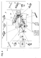
- FIG. 4 illustrates a printed image of a parts catalog generated by the image processing apparatus 100.
- the following processes are performed, for example, when a user issues a request for generating a printed image of a parts catalog of a product model assembled with a plurality of parts stored in the 3D data 21 and the parts list 22 depicted in FIG. 1 .
- the individual image generator 23 acquires data of each part of the product model listed on the parts list 22 from the 3D data 21 and generates an individual image of each part based on the acquired data in step S101. It is to be noted that when picture image data and the like other than 3D data is supplied as an individual image, the picture image may be used. Such image data other than 3D data may be supplied by a known method.
- the individual image of each part generated in step S101 corresponds to each of images P1 to P14 positioned outside a screen 50 depicted in FIG. 4 .
- step S102 the assembly image generator 24 generates a parts assembly image representing a whole image of the product model assembled with all parts constituting the product model.
- the assembly image generator 24 highlights a part specified by the user based on the identification information of a name of the part and the like acquired from the parts list 22, so that the specified part is displayed in a way that stands out on the parts assembly image of the product model.
- the parts assembly image generated by the assembly image generator 24 in step S102 is displayed on the screen 50 as illustrated in FIG. 4 .
- Parts surrounded by rectangular frames B1 to B14 and indicated by a solid line are to be highlighted, while another parts indicated by a broken line are not highlighted.
- the assembly image generator 24 may generate a parts assembly image of each unit.
- step S103 the boundary information calculator 25 calculates boundary information of each part highlighted on the parts assembly image generated in step S102.
- This calculation is performed for obtaining a position of each part highlighted on the assembly image.
- the position of each part highlighted is represented by positional coordinates of a center of the part.
- the boundary information calculator 25 may obtain coordinates of an outline of each part as boundary information of the part, according to this illustrative embodiment, the boundary information calculator 25 calculates coordinates of a rectangle surrounding the outline of the part, since the calculation of the rectangle easily derives a center position of the part with a small amount of data. Accordingly, the boundary information of each part is represented by coordinates of two points, (Xmax, Ymax) and (Xmin, Ymin), in an x- and y- (two-dimensional) coordinate system mapped onto the parts assembly image. Each side of the rectangle representing the boundary information of each part is parallel to one of the axes of the x and y coordinates.
- the rectangular frames B1 to B14 on the assembly image displayed on the screen 50 in FIG. 4 correspond to the rectangle calculated by the boundary information calculator 25 as boundary information of each part highlighted on the parts assembly image in step S103, and surround the outline of each part highlighted and indicated by the solid line, respectively.
- step S104 the individual image arrangement calculator 26 calculates a position of arrangement of the individual image of each part based on the boundary information of the part highlighted calculated by the boundary information calculator 25 in step S103. This calculation is used for generating a printed image of a parts catalog showing a parts assembly image of a product model with a particular part highlighted surrounded by an individual image of each highlighted part generated by the individual image generator 23 in step S101. It is to be noted that the individual image of each part is arranged around the parts assembly image, such that leading lines drawn from each of the highlighted parts on the parts assembly image to the corresponding individual image do not intersect.
- the individual image arrangement calculator 26 obtains one or more straight lines dividing the assembly image to equally distribute the center positions of each part calculated based on the boundary information of the highlighted part on the assembly image, so that the individual image of each part is positioned in a corresponding area defined by the straight lines.
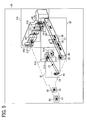
- FIG. 5 illustrates the parts assembly image on the screen 50.
- Each part of the product model indicated by a solid line is highlighted and surrounded by rectangular frames B1 to B14 as boundary information.
- the individual image arrangement calculator 26 calculates a position of arrangement of the individual image of each part around the assembly image.
- the individual image arrangement calculator 26 obtains straight lines dividing the assembly image into left, right, top, and bottom areas, such that each area includes an equal number of parts. However, since each area includes a plurality of parts, leading lines are drawn from each of the highlighted parts on the assembly image to the corresponding individual images so as not to intersect.
- FIG. 3B is a flowchart of the process performed by the individual image arrangement calculator 26 in step S104 depicted in FIG. 3A .
- FIG. 6 illustrates a first dividing line L1 dividing the assembly image.
- FIG. 7 illustrates a second dividing line L2 dividing the assembly image.
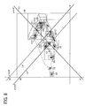
- FIG. 8 illustrates a third dividing line L3 dividing the assembly image.
- step S104-1 the individual image arrangement calculator 26 obtains a center position of the highlighted part on the assembly image based on the boundary information of the part calculated by the boundary information calculator 25 in step S103. Since the boundary information includes coordinate values of two points representing the rectangle surrounding the outline of the part, that is, the rectangular frames B1 to B14, the individual image arrangement calculator 26 calculates the center position of the rectangle based on the coordinate values of two points by a simple calculation. As illustrated in FIG. 5 , center points C1 to C14 indicate a center of the rectangular frames B1 to B14 as a center position of each of the highlighted parts as well.
- step S104-2 as illustrated in FIG. 6 , the individual image arrangement calculator 26 obtains a straight line L1 dividing the assembly image into the left upper area and the lower right area, also referred to as a dividing line, such that an equal number of the center points C1 to C14 of each of the highlighted parts obtained in the step S104-1 is included in the left upper area and the lower right area.
- the dividing line L1 equally distributes the center points C1 to C14 of each part. That is, the left upper area includes a group of the center points C1, C2, C3, C4, C12, C13, and C14, while the lower right area includes a group of the center points C5, C6, C7, C8, C9, C10, and C11.
- the individual image arrangement calculator 26 After the individual image arrangement calculator 26 obtains the straight line L1 dividing the assembly image into the left upper area and the lower right area in step S104-2, the individual image arrangement calculator 26 obtains a straight line L2 further dividing the assembly image to distribute an equal number of the center points C1, C2, C3, C4, C12, C13, and C14 of each part into each of the divided areas in step S104-3.
- the straight line L2 obtained by the individual image arrangement calculator 26 further divides the left upper area into the upper area and the left area, as illustrated in FIG. 7 .
- the dividing line L2 equally distributes the center points C1, C2, C3, C4, C12, C13, and C14 into the upper area and the left area, so that the upper area includes C12, C13, and C14, while the left area includes C1, C2, C3, and C4.
- step S104-4 the individual image arrangement calculator 26 obtains a straight line L3 dividing the lower right area of the assembly image into right and lower areas.
- the straight line L3 divides the lower right area of the assembly image to equally distribute the center points C5, C6, C7, C8, C9, C10, and C11 into the right area and the lower area, so that the right area includes C8, C9, C10, and C11, while the left area includes C5, C6, and C7.
- the straight lines L1, L2, and L3 having an inclination of +1 or -1 in the x-y coordinate system equally divide the assembly image into upper, lower, left, and right areas to equally distribute all the parts into each of the divided areas.
- the divided areas are substantially equal in size and have a sector-like shape from the center of the assembly image to the edge of the screen 50 in vertical and horizontal directions (directions of x-, y-axes), respectively.
- the individual image arrangement calculator 26 depicted in FIG. 2 obtains the dividing lines L1, L2, and L3 to divide the assembly image into four areas to arrange the individual images of each part in the corresponding areas. Therefore, a storage device, for example, the memory 12 or the external storage device 15, depicted in FIG. 1 , stores information on the arrangement of each part obtained by the individual image arrangement calculator 26, which is used for generation of a printed image of a parts catalog.
- the individual image arrangement calculator 26 compares coordinate values of a center point of each part included in the same area to define arrangement of the part. According to this illustrative embodiment, when the assembly image is divided into the upper, lower, left, and right areas, as illustrated in FIG. 8 , the individual image arrangement calculator 26 defines a position of the individual image by arranging the individual image in the order of the x- or y- coordinate values of the center point of each part on the assembly image, thereby preventing crossing of the leading lines.
- the individual image arrangement calculator 26 compares coordinate values of the center point of each part included in the same area to define the order of arrangement of the individual image in the divided area in step S104-5. It is to be noted that the coordinate value of the center point of each part to be compared corresponds to the x- and y-coordinate values obtained in step S104-1.
- the individual image arrangement calculator 26 determines the order of arrangement of the individual image of each part included in the upper and the lower areas, the individual image arrangement calculator 26 compares x-coordinate values of the center point of each part to determine the individual image to be arranged to the left of the assembly image in the order of increasing x-coordinate values. Therefore, as illustrated in FIG. 8 , the center points C14, C13, and C12 are arranged to the left in the upper area of the assembly image, and the center points C5, C6, and C7 are arranged to the left in the lower area of the assembly image thereof.
- the individual image arrangement calculator 26 determines the order of arrangement of the individual image of each part included in the left and the right areas, the individual image arrangement calculator 26 compares y-coordinate values of the center point of each part to determine the individual image to be arranged from the top of the assembly image in the order of decreasing y coordinate values. Therefore, the center points C1, C2, C3, and C4 are arranged from the top in the left area of the assembly image, and C11, C10, C9, and C8 are arranged from the top in the right area thereof.
- the individual image arrangement calculator 26 provides the print data generator 27 depicted in FIG. 2 with information on the center position of each part, information on which area each part belongs to on the assembly image, and information on an arrangement of each part in each area.
- the print data generator 27 receives a result obtained from the previous processes in steps S101 through S104 and generates a printed image of a parts catalog in step S105.
- the print data generator 27 receives the parts assembly image with a specific part highlighted from the assembly image generator 24 and receives the individual image of the highlighted part from the individual image generator 23. The print data generator 27 then arranges the individual image around the parts assembly image according to the conditions for determining the position of arrangement of the individual image received from the individual image arrangement calculator 26. Thereafter, the print data generator 27 draws a leading line connecting the highlighted part on the assembly image with the individual image arranged around the assembly image according to the above conditions.
- the individual image arrangement calculator 26 defines the information of which area each part belongs to on the assembly image and the information on the order of arrangement of each part in each area. Therefore, based on the above information, the print data generator 27 positions the individual image of each part.
- the print data generator 27 serving as an output image generator, generates an image of a parts catalog in which a leading line connects the individual image of each part to the center position of the corresponding part on the assembly image.
- the image processing apparatus 100 serving as a parts catalog printed image creation system, generates a printed image of the parts catalog.
- the screen 50 displays each part highlighted, indicated by a solid line, on the parts assembly image, indicated by a dotted line, while a screen 50' displays individual images P1 to P14 corresponding to each of the highlighted parts positioned around the parts assembly image.
- the individual images P1 to P14 are arranged in the upper, lower, left, and right areas to which each part belongs, respectively, as described above by referring to FIGS. 6 , 7 , and 8 , that is, on the upper, lower, left, and right side of the screen 50', respectively.
- the individual images P1, P2, P3, and P4 are positioned on the left side of the screen 50'.
- the individual image of each of the plurality of parts provided in the same area is arranged in the order of increasing or decreasing coordinate values of the center position of each part.
- the individual images P14, P13, and P12 included in the upper area are arranged to the left in the order of increasing x-coordinate values.
- the image processing apparatus 100 depicted in FIG. 1 serving as a parts catalog printed image creation system, generates the printed image of the parts catalog in which the individual image of each part of the product model is arranged around the parts assembly image of the product model using the above-described method.
- the image processing apparatus 100 can properly and efficiently provide the user with information on the structure and the like of the product.
- This invention may be conveniently implemented using a conventional general-purpose digital computer programmed according to the teachings of the present specification, as will be apparent to those skilled in the computer art.
- Appropriate software coding can readily be prepared by skilled programmers based on the teachings of the present disclosure, as will be apparent to those skilled in the software art.
- the present invention may also be implemented by the preparation of application specific integrated circuits or by interconnecting an appropriate network of conventional component circuits, as will be readily apparent to those skilled in the art.
Landscapes
- Engineering & Computer Science (AREA)
- Business, Economics & Management (AREA)
- Physics & Mathematics (AREA)
- Theoretical Computer Science (AREA)
- General Physics & Mathematics (AREA)
- Economics (AREA)
- Computer Hardware Design (AREA)
- Geometry (AREA)
- General Engineering & Computer Science (AREA)
- Human Resources & Organizations (AREA)
- General Business, Economics & Management (AREA)
- Accounting & Taxation (AREA)
- Finance (AREA)
- Development Economics (AREA)
- Tourism & Hospitality (AREA)
- Entrepreneurship & Innovation (AREA)
- Strategic Management (AREA)
- Marketing (AREA)
- Operations Research (AREA)
- Quality & Reliability (AREA)
- Computer Graphics (AREA)
- Evolutionary Computation (AREA)
- Software Systems (AREA)
- Computational Mathematics (AREA)
- Mathematical Analysis (AREA)
- Mathematical Optimization (AREA)
- Pure & Applied Mathematics (AREA)
- Processing Or Creating Images (AREA)
Applications Claiming Priority (1)
| Application Number | Priority Date | Filing Date | Title |
|---|---|---|---|
| JP2008016811A JP4990173B2 (ja) | 2008-01-28 | 2008-01-28 | 画像処理装置、画像処理方法及びプログラム |
Publications (2)
| Publication Number | Publication Date |
|---|---|
| EP2083393A2 true EP2083393A2 (de) | 2009-07-29 |
| EP2083393A3 EP2083393A3 (de) | 2013-03-13 |
Family
ID=40689656
Family Applications (1)
| Application Number | Title | Priority Date | Filing Date |
|---|---|---|---|
| EP09250189A Withdrawn EP2083393A3 (de) | 2008-01-28 | 2009-01-23 | Bildverarbeitungsvorrichtung, Bildverarbeitungsverfahren und Datenträger, der ein Programm zum Bewirken, dass eine Bildverarbeitungsvorrichtung ein Bildverarbeitungsverfahren ausführt, speichert |
Country Status (4)
| Country | Link |
|---|---|
| US (1) | US8149239B2 (de) |
| EP (1) | EP2083393A3 (de) |
| JP (1) | JP4990173B2 (de) |
| CN (1) | CN101499179B (de) |
Families Citing this family (6)
| Publication number | Priority date | Publication date | Assignee | Title |
|---|---|---|---|---|
| JP2009054018A (ja) * | 2007-08-28 | 2009-03-12 | Ricoh Co Ltd | 画像検索装置、画像検索方法及びプログラム |
| JP5598024B2 (ja) * | 2010-03-04 | 2014-10-01 | 株式会社リコー | 部品管理システム、部品管理装置、部品管理プログラム及び部品管理方法 |
| US8473362B2 (en) | 2011-04-07 | 2013-06-25 | Ebay Inc. | Item model based on descriptor and images |
| DE112014000784T5 (de) * | 2013-02-12 | 2015-12-03 | Mitsubishi Electric Corporation | Zeichnungsdatenerzeugungsgerät, Zeichnungsdatenerzeugungsverfahren und Anzeigegerät |
| JP6467879B2 (ja) * | 2014-11-11 | 2019-02-13 | 富士通株式会社 | 引出線配置位置決定プログラム、引出線配置位置決定方法および引出線配置位置決定装置 |
| JP2017130004A (ja) * | 2016-01-20 | 2017-07-27 | 株式会社ハイパーエンジニアリング | 施工検査システム及びその方法 |
Citations (1)
| Publication number | Priority date | Publication date | Assignee | Title |
|---|---|---|---|---|
| JP2008016811A (ja) | 2006-07-04 | 2008-01-24 | Hynix Semiconductor Inc | フォトレジストのストリップ方法 |
Family Cites Families (20)
| Publication number | Priority date | Publication date | Assignee | Title |
|---|---|---|---|---|
| JPH01264367A (ja) * | 1988-04-15 | 1989-10-20 | Hitachi Ltd | ダイナミックフォーカス回路 |
| US5216612A (en) * | 1990-07-16 | 1993-06-01 | R. J. Reynolds Tobacco Company | Intelligent computer integrated maintenance system and method |
| JP2710882B2 (ja) * | 1991-08-30 | 1998-02-10 | 三菱電機株式会社 | データ自動配置装置 |
| JPH0683881A (ja) * | 1992-05-14 | 1994-03-25 | Sanyo Electric Co Ltd | 組立図における部品番号の付与方法 |
| JP3353212B2 (ja) * | 1993-03-24 | 2002-12-03 | 東京瓦斯株式会社 | 引出線自動作成方法および引出線自動作成システム |
| JP2003076724A (ja) | 2001-09-04 | 2003-03-14 | Toyota Keeramu:Kk | 分解図自動作成装置、分解図自動作成方法及びその記録媒体 |
| JP3831290B2 (ja) * | 2002-05-07 | 2006-10-11 | 株式会社日立製作所 | Cadデータの評価方法及び評価装置 |
| JP2004246762A (ja) | 2003-02-17 | 2004-09-02 | Olympus Corp | 作業マニュアル作成支援システム |
| JP2005004489A (ja) * | 2003-06-12 | 2005-01-06 | Toyota Industries Corp | 部品カタログ作成装置および部品カタログ作成プログラム |
| JP3786127B2 (ja) * | 2004-07-20 | 2006-06-14 | 株式会社日立製作所 | 分解組立図作成装置および方法 |
| JP4825594B2 (ja) * | 2005-07-07 | 2011-11-30 | 株式会社リコー | パーツ選択装置 |
| US20070100713A1 (en) * | 2005-11-03 | 2007-05-03 | Jim Del Favero | Identifying inventory items within an image |
| JP2007219907A (ja) * | 2006-02-17 | 2007-08-30 | Ricoh Co Ltd | パーツカタログ・システム、パーツカタログ作成方法、プログラムおよび記録媒体 |
| JP2007280354A (ja) * | 2006-03-16 | 2007-10-25 | Ricoh Co Ltd | 三次元形状処理装置、三次元形状処理方法、三次元形状処理プログラム、記録媒体、パーツカタログ・システム、パーツカタログ作成方法、及びプログラム |
| JP4798579B2 (ja) * | 2006-04-21 | 2011-10-19 | 株式会社リコー | 部品カタログ生成システム、部品カタログ生成方法、プログラムおよび記録媒体 |
| JP4809121B2 (ja) * | 2006-05-15 | 2011-11-09 | 株式会社リコー | パーツカタログ作成方法およびパーツカタログ作成装置およびプログラム |
| JP4890116B2 (ja) * | 2006-06-19 | 2012-03-07 | 株式会社リコー | パーツカタログ作成方法およびパーツカタログ作成装置 |
| JP4838079B2 (ja) * | 2006-09-07 | 2011-12-14 | 株式会社リコー | パーツ識別画像作成装置およびプログラムおよびコンピュータ読み取り可能な記憶媒体 |
| US20080086324A1 (en) * | 2006-09-14 | 2008-04-10 | Junichi Yamagata | Parts managing system, parts managing method, and computer program product |
| JP5041801B2 (ja) * | 2006-12-26 | 2012-10-03 | 本田技研工業株式会社 | 作業内容を表示するためのプログラム |
-
2008
- 2008-01-28 JP JP2008016811A patent/JP4990173B2/ja not_active Expired - Fee Related
-
2009
- 2009-01-23 EP EP09250189A patent/EP2083393A3/de not_active Withdrawn
- 2009-01-23 US US12/358,421 patent/US8149239B2/en not_active Expired - Fee Related
- 2009-01-24 CN CN2009100028203A patent/CN101499179B/zh not_active Expired - Fee Related
Patent Citations (1)
| Publication number | Priority date | Publication date | Assignee | Title |
|---|---|---|---|---|
| JP2008016811A (ja) | 2006-07-04 | 2008-01-24 | Hynix Semiconductor Inc | フォトレジストのストリップ方法 |
Also Published As
| Publication number | Publication date |
|---|---|
| JP2009176248A (ja) | 2009-08-06 |
| EP2083393A3 (de) | 2013-03-13 |
| CN101499179A (zh) | 2009-08-05 |
| CN101499179B (zh) | 2011-12-07 |
| JP4990173B2 (ja) | 2012-08-01 |
| US20090189899A1 (en) | 2009-07-30 |
| US8149239B2 (en) | 2012-04-03 |
Similar Documents
| Publication | Publication Date | Title |
|---|---|---|
| US6025847A (en) | Three dimensional modeling system with visual feedback | |
| CN100524327C (zh) | 零件目录作成方法,作成装置及显示装置 | |
| JP5062884B2 (ja) | 画像検索装置、画像検索方法及びプログラム | |
| EP1898327B1 (de) | Bildprozessor zur Teileidentifikation, Programm zur Erzeugung eines Teileidentifikationsbildes und Aufzeichnungsmedium zu deren Speicherung | |
| US8149239B2 (en) | Image processing apparatus, image processing method, and storage medium storing a program for causing an image processing apparatus to execute an image processing method | |
| US6683606B1 (en) | Virtual architecture experience method and apparatus | |
| JP2007280354A (ja) | 三次元形状処理装置、三次元形状処理方法、三次元形状処理プログラム、記録媒体、パーツカタログ・システム、パーツカタログ作成方法、及びプログラム | |
| JPH0765201A (ja) | 形状モデリング装置及び形状モデリング方法 | |
| US20050093860A1 (en) | Information processing apparatus and method, program for executing said method, and storage medium storing said program | |
| JP5047124B2 (ja) | パーツ識別画像作成装置及び同方法、パーツ識別表示装置及び同方法、プログラム及び記憶媒体 | |
| JP2966376B2 (ja) | 薄板金属製作設備全体にわたって設計製作情報を分配する装置と方法 | |
| US8477133B2 (en) | Method and apparatus for generating three-dimensional finite element mesh | |
| JP4870581B2 (ja) | パーツカタログ作成システム、コンピュータが実行するためのプログラム、およびコンピュータが読み取り可能な記録媒体 | |
| JP5372590B2 (ja) | 情報処理装置、情報処理方法、およびプログラム | |
| JP3181877B2 (ja) | 3次元画像作成装置 | |
| JP2008117113A (ja) | 画像生成装置および方法、画像生成プログラム | |
| JP4915522B2 (ja) | 図形処理装置 | |
| JP2001202396A (ja) | プリント基板cadの3次元表示方法およびその装置 | |
| JP4949001B2 (ja) | 画像処理装置およびプログラムおよび記憶媒体 | |
| JP4979358B2 (ja) | 画像処理装置および画像処理方法およびプログラムおよび記憶媒体 | |
| JP7262655B2 (ja) | 寸法作成装置、寸法作成方法及びプログラム | |
| JP3254276B2 (ja) | 貼り形状算出装置 | |
| JP6264208B2 (ja) | 表示プログラム、表示方法、および表示装置 | |
| JPH07175944A (ja) | 3次元モデルの配置方法 | |
| JPH0749965A (ja) | 形状作成支援方法及びその装置 |
Legal Events
| Date | Code | Title | Description |
|---|---|---|---|
| PUAI | Public reference made under article 153(3) epc to a published international application that has entered the european phase |
Free format text: ORIGINAL CODE: 0009012 |
|
| AK | Designated contracting states |
Kind code of ref document: A2 Designated state(s): AT BE BG CH CY CZ DE DK EE ES FI FR GB GR HR HU IE IS IT LI LT LU LV MC MK MT NL NO PL PT RO SE SI SK TR |
|
| AX | Request for extension of the european patent |
Extension state: AL BA RS |
|
| PUAL | Search report despatched |
Free format text: ORIGINAL CODE: 0009013 |
|
| AK | Designated contracting states |
Kind code of ref document: A3 Designated state(s): AT BE BG CH CY CZ DE DK EE ES FI FR GB GR HR HU IE IS IT LI LT LU LV MC MK MT NL NO PL PT RO SE SI SK TR |
|
| AX | Request for extension of the european patent |
Extension state: AL BA RS |
|
| RIC1 | Information provided on ipc code assigned before grant |
Ipc: G06T 19/00 20110101ALI20130207BHEP Ipc: G06F 17/50 20060101AFI20130207BHEP |
|
| 17P | Request for examination filed |
Effective date: 20130711 |
|
| RBV | Designated contracting states (corrected) |
Designated state(s): AT BE BG CH CY CZ DE DK EE ES FI FR GB GR HR HU IE IS IT LI LT LU LV MC MK MT NL NO PL PT RO SE SI SK TR |
|
| AKX | Designation fees paid |
Designated state(s): DE FR GB |
|
| GRAP | Despatch of communication of intention to grant a patent |
Free format text: ORIGINAL CODE: EPIDOSNIGR1 |
|
| STAA | Information on the status of an ep patent application or granted ep patent |
Free format text: STATUS: GRANT OF PATENT IS INTENDED |
|
| RIC1 | Information provided on ipc code assigned before grant |
Ipc: G06Q 10/08 20120101AFI20180730BHEP Ipc: G06T 19/00 20110101ALI20180730BHEP Ipc: G06T 15/10 20110101ALI20180730BHEP Ipc: G06F 17/50 20060101ALI20180730BHEP |
|
| INTG | Intention to grant announced |
Effective date: 20180814 |
|
| STAA | Information on the status of an ep patent application or granted ep patent |
Free format text: STATUS: THE APPLICATION IS DEEMED TO BE WITHDRAWN |
|
| 18D | Application deemed to be withdrawn |
Effective date: 20190103 |