EP2083176B1 - Unité de ventilateur dotée d'un ventilateur axial - Google Patents
Unité de ventilateur dotée d'un ventilateur axial Download PDFInfo
- Publication number
- EP2083176B1 EP2083176B1 EP08021713A EP08021713A EP2083176B1 EP 2083176 B1 EP2083176 B1 EP 2083176B1 EP 08021713 A EP08021713 A EP 08021713A EP 08021713 A EP08021713 A EP 08021713A EP 2083176 B1 EP2083176 B1 EP 2083176B1
- Authority
- EP
- European Patent Office
- Prior art keywords
- ring
- fan unit
- unit according
- fan
- external tube
- Prior art date
- Legal status (The legal status is an assumption and is not a legal conclusion. Google has not performed a legal analysis and makes no representation as to the accuracy of the status listed.)
- Active
Links
- 238000009423 ventilation Methods 0.000 title description 2
- 239000004033 plastic Substances 0.000 claims abstract description 18
- 229920003023 plastic Polymers 0.000 claims abstract description 18
- 239000000725 suspension Substances 0.000 claims description 51
- 238000005516 engineering process Methods 0.000 claims description 5
- 239000011324 bead Substances 0.000 claims description 4
- 239000013536 elastomeric material Substances 0.000 claims description 4
- 230000010355 oscillation Effects 0.000 claims description 4
- 239000000853 adhesive Substances 0.000 claims description 2
- 230000001070 adhesive effect Effects 0.000 claims description 2
- 238000010276 construction Methods 0.000 claims description 2
- 238000001746 injection moulding Methods 0.000 claims description 2
- 238000004023 plastic welding Methods 0.000 claims description 2
- 230000002093 peripheral effect Effects 0.000 claims 1
- 238000013016 damping Methods 0.000 abstract description 19
- 229920001971 elastomer Polymers 0.000 abstract description 5
- 230000032258 transport Effects 0.000 abstract description 2
- 239000000806 elastomer Substances 0.000 abstract 1
- 239000000463 material Substances 0.000 abstract 1
- 239000012528 membrane Substances 0.000 description 4
- 230000000284 resting effect Effects 0.000 description 3
- 238000011161 development Methods 0.000 description 2
- 230000018109 developmental process Effects 0.000 description 2
- 239000002184 metal Substances 0.000 description 2
- 238000012986 modification Methods 0.000 description 2
- 230000004048 modification Effects 0.000 description 2
- 229920000642 polymer Polymers 0.000 description 2
- 239000007779 soft material Substances 0.000 description 2
- 230000005540 biological transmission Effects 0.000 description 1
- 230000001419 dependent effect Effects 0.000 description 1
- 239000006260 foam Substances 0.000 description 1
- 229920001821 foam rubber Polymers 0.000 description 1
- 238000010438 heat treatment Methods 0.000 description 1
- 238000004519 manufacturing process Methods 0.000 description 1
- 229920002635 polyurethane Polymers 0.000 description 1
- 239000004814 polyurethane Substances 0.000 description 1
- 239000003351 stiffener Substances 0.000 description 1
Images


Classifications
-
- F—MECHANICAL ENGINEERING; LIGHTING; HEATING; WEAPONS; BLASTING
- F04—POSITIVE - DISPLACEMENT MACHINES FOR LIQUIDS; PUMPS FOR LIQUIDS OR ELASTIC FLUIDS
- F04D—NON-POSITIVE-DISPLACEMENT PUMPS
- F04D29/00—Details, component parts, or accessories
- F04D29/40—Casings; Connections of working fluid
- F04D29/52—Casings; Connections of working fluid for axial pumps
- F04D29/522—Casings; Connections of working fluid for axial pumps especially adapted for elastic fluid pumps
- F04D29/526—Details of the casing section radially opposing blade tips
-
- F—MECHANICAL ENGINEERING; LIGHTING; HEATING; WEAPONS; BLASTING
- F04—POSITIVE - DISPLACEMENT MACHINES FOR LIQUIDS; PUMPS FOR LIQUIDS OR ELASTIC FLUIDS
- F04D—NON-POSITIVE-DISPLACEMENT PUMPS
- F04D29/00—Details, component parts, or accessories
- F04D29/66—Combating cavitation, whirls, noise, vibration or the like; Balancing
- F04D29/661—Combating cavitation, whirls, noise, vibration or the like; Balancing especially adapted for elastic fluid pumps
- F04D29/668—Combating cavitation, whirls, noise, vibration or the like; Balancing especially adapted for elastic fluid pumps damping or preventing mechanical vibrations
-
- F—MECHANICAL ENGINEERING; LIGHTING; HEATING; WEAPONS; BLASTING
- F16—ENGINEERING ELEMENTS AND UNITS; GENERAL MEASURES FOR PRODUCING AND MAINTAINING EFFECTIVE FUNCTIONING OF MACHINES OR INSTALLATIONS; THERMAL INSULATION IN GENERAL
- F16F—SPRINGS; SHOCK-ABSORBERS; MEANS FOR DAMPING VIBRATION
- F16F15/00—Suppression of vibrations in systems; Means or arrangements for avoiding or reducing out-of-balance forces, e.g. due to motion
- F16F15/02—Suppression of vibrations of non-rotating, e.g. reciprocating systems; Suppression of vibrations of rotating systems by use of members not moving with the rotating systems
- F16F15/04—Suppression of vibrations of non-rotating, e.g. reciprocating systems; Suppression of vibrations of rotating systems by use of members not moving with the rotating systems using elastic means
- F16F15/08—Suppression of vibrations of non-rotating, e.g. reciprocating systems; Suppression of vibrations of rotating systems by use of members not moving with the rotating systems using elastic means with rubber springs ; with springs made of rubber and metal
Definitions
- the invention relates to a fan unit with an axial fan.
- the DE 20 2005 011 514 U1 concerns different versions of fan units.
- the fan is in an annular housing part, and this is connected via six rubber cords with an external mounting flange.
- a conical part made of polyurethane is provided, whereby the air losses are reduced and the efficiency is improved.
- a fan unit which uses an outer and an inner frame member which are interconnected by a rubber membrane.
- the axial fan is attached to the inner frame member.
- the rubber membrane is intended to prevent or reduce the transmission of structure-borne noise to the outer frame element.
- the US 4,908,929 uses a fan, which is connected by a foam rubber disc with a housing, whereby a noise attenuation is to be achieved.
- a noise attenuation is to be achieved.
- left, right, front, back, top, and bottom refer to the respective drawing figure and may vary from one drawing figure to another depending on a particular orientation (portrait or landscape). Identical or equivalent parts are denoted by the same reference numerals in the various figures and usually described only once.
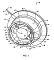
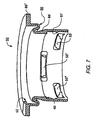
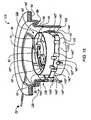
- Fig. 1 shows a first embodiment of a fan unit 10 with an axial fan 20 and a vibration and noise damping device 30 in a rear view.
- the axial fan 20 has an approximately hollow cylindrical air guide tube 22, which can be uniformly formed of plastic or metal or any mixed form thereof.
- On the outer circumference of the air guide tube 22 a plurality of suspension members 23 are provided from an elastomeric material, of which in Fig. 1 the suspension members 23 'to 23 IV are visible.
- a fan 24 is arranged, which is arranged rotatably about a rotation axis 23 which extends along the longitudinal axis of the air guide tube 22.
- the fan 24 has fan blades 26 'to 26 V , whose shape is adapted to the shape of the inside of the air duct 22.
- the fan 20 has a motor 21 (FIG. Fig. 4 and 5 ) for driving its fan wheel 24, which motor 21 is preferably designed as an electronically commutated external rotor motor. He has a rotor bell 25 ( Fig. 1 ) to which the fan 24 is attached.
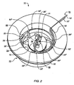
- a mounting flange 38 ( Fig. 2 ), which via thin holding webs 29 'to 29 III ( Fig. 2 ) is connected to the air guide tube 22, as at Fig. 2 described.
- the motor 21 is connected to a flexible electrical connection line 70. This is on a printed circuit board 90 ( Fig. 5 ) of the motor 21 soldered.
- the fan 20 has two lines 70 'and 70 "for supplying an operating voltage, in many cases further lines are provided, eg for a tacho signal or an alarm signal.
- the fan 20 is arranged in the vibration and noise damping device 30.
- This has a first ring 40 for the elastic suspension of the fan 20, a connected thereto tubular extension 50 for vibration damping, and a second ring 60 for connecting the fan unit 10 with a support member 15 (FIGS. Fig. 5 ).
- the first ring 40 thus carries the fan 20 and is therefore also referred to below as the "carrier ring”.
- the extension 50 is supported relative to the carrier part. Therefore, this ring 60 is also referred to as a "support ring”.
- the tubular extension 50 is formed as a bellows and has a spring element 86 with a predetermined Oscillation behavior for vibration and noise damping, which in Fig. 3 is described in detail.
- the support ring 40 and the support ring 60 are preferably formed of a hard plastic and the tubular extension 50 of a soft material.
- the tubular extension 50 can be connected to the carrier ring 40 and / or the support ring 60, for example by injection molding, a clamping connection, an adhesive connection or plastic welding.
- suspension members 55 On support ring 40 for attaching the suspension members 23 more suspension members 55 are provided from a hard plastic, of which Fig. 1 the suspension links 55 'to 55 IV are visible.
- the suspension members 55 may be at least partially formed on the inner circumference of the tubular extension 50 of a soft plastic, as in Fig. 3 and 7 described.
- the motor 21 drives the fan 24 in such a way that it rotates about its axis of rotation 23, for example in the direction of an arrow 27 (FIG. Fig. 1 ).
- the undesirable vibrations and noises arising, for example, from an imbalance of the fan 20 are damped by the device 30, as in FIG Fig. 5 described.
- Fig. 2 shows a front view of the fan unit 10 of Fig. 1 in which a further suspension member 23 V is shown, and the assembly of the fan 20 for driving the fan 24 associated motor 21 is illustrated on a attached to the air duct 22 flange plate 38, the thin support webs 29 'to 29 III with the air duct 22nd connected is.
- a bearing element 80 is arranged, for example, a bearing tube on which the rotor of the motor 21 is mounted.
- the element 80 is provided with three screws 82, of which in Fig. 2 only the screws 82 'and 82 "are visible, attached to the flange 38.
- Fig. 2 also shows the cable guide of the connecting line 70.
- This is the motor 21 via the flange 38, where it is attached to a bracket 72, to the inner wall of the tubular extension 50, along there to an opening 52 and through this outwardly in the radial direction.
- Fig. 3 shows an embodiment in which the suspension members 55 are formed of a soft plastic as an integral part of the tubular extension 50, which at least partially surrounds the support ring 40.
- the carrier ring 40 has recesses 42, of which in Fig. 3 only the recesses 42 ', 42 ", 42 IV and 42 V are visible, through which the suspension links 55 extend.
- the suspension members 55 are formed as support elements on which the suspension members 23 rest after the assembly of the fan unit 10.
- the recesses 42 are preferably formed such that the suspension members 23 at least partially engage in this, in order to ensure jamming or hooking in the recesses 42 and thus a stable support on the associated support elements.
- Ein stressglieder 55 are formed with groove-shaped recesses 28 and reinforced side portions 31 and 33, respectively.
- the support member 23 VI has a groove-shaped recess 28 VI and reinforced side portions 31 VI and 33 VI .
- the bearing member 80 has another fastener 82 '''and the spring member 86 is disposed between a hollow cylindrical portion 88' and a collar 88 'of the tubular extension 50.
- the portion 88' is integral with the support ring 40 and collar 88 '. connected to the support ring 60.
- the spring element 86 has a predetermined vibration behavior to allow for vibration and noise damping relative movement between the support ring 40 and the support ring 60, and is formed according to a first embodiment as a curved, approximately S-shaped vibration membrane.
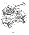
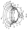
- Fig. 4 shows a partially cutaway perspective view of the fan unit 10th Fig. 4 illustrates on the one hand the resting on the suspension links 55 suspension members 23, and on the other hand, an annular shoulder 49, against which the support ring 40 is applied.
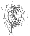
- Fig. 5 shows the arranged in a support member 15 fan unit 10.
- the support member 15 is formed for example of foam, which is used for upholstering a vehicle seat.
- the fan unit 10 can be used for ventilation or heating of the seat, which is sunk as shown in the support member 15 in order to ensure a predetermined distance between the collar 88 "and a corresponding seat surface.
- FIG. 5 shows Fig. 5 the motor 21 with a stator assembly 37 and a printed circuit board 90, to which the connecting line 70 is connected.
- the motor 21 can be realized with any, electronically commutated electric motor, which is suitable for driving the axial fan 20, so that a detailed description of the motor 21 can be dispensed with.
- Fig. 5 the suspension of the air duct tube 22 in the vibration and noise damping device 30 by the Auf vongliedern 55 resting on the suspension members 23, with only the suspension members 55 "and 55 IV resting suspension members 23" and 23 IV are visible.
- the device 30 has a predetermined number of degrees of freedom both in the horizontal and in the vertical direction.
- Fig. 6 shows a sectional view of the vibration and noise damping device 30 according to an embodiment.
- Fig. 6 illustrates the provided on the tubular extension 50 Einitatiglieder 55 'to 55 "', which pass through the provided in the support ring 40 recesses 42 'to 42''' Fig. 6 a provided on the extension 50, annular projection 97, which in an am Support ring 40 provided, annular groove 96 engages to ensure a non-slip connection between the support ring 40 and the extension 50.
- Fig. 7 shows a sectional view of the tubular extension 50, which illustrates the provided thereon Ein vonglieder 55 'to 55''', the annular projection 97 and the annular shoulder 49.
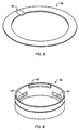
- Fig. 8 shows a perspective view of the support ring 60, which has a bulge 62 for guiding the connecting line 70 of Fig. 1 has
- Fig. 9 shows a perspective view of the support ring 40, which illustrates the provided therein recesses 42 'to 42'''.
- Fig. 10 shows a tubular extension 50 'according to a second embodiment, which is used instead of the above-described extension 50 with the vibration and noise damping device 30.
- the tubular extension 50 ' has a modified spring element 86' with a first circumferential bead 86 "which connects the collar 88" to the cylindrical section 88 'and has an im - in Fig. 10 - the upper portion of the portion 88 'provided second designswulst 86''' on.
- the extension 50' has a different oscillation behavior than the oscillation membrane extension 50 described above, ie the spring element 86 or 86 'can be configured in different ways, as appropriate Accordingly, many possible embodiments of the spring element 86 or 86 'are to be understood as part of the invention.
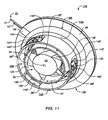
- the Fig.11 to 19 show another embodiment of a fan unit 110.
- components whose functionality of the functionality of components of the Fig. 1 to 10 described fan unit 10 provided with the enlarged by the number 100 reference numerals of the components of the fan unit 10. Accordingly, the description of such components will not be repeated in detail below.
- Fig. 11 shows a second embodiment of a fan unit 110 with an axial fan 120 and a vibration and noise damping device 130 in a rear view.
- the axial fan 120 substantially corresponds to the axial fan 20 of the first embodiment with the motor 21, which in Fig. 14 however, it has a modified air guide tube 122.
- This is approximately hollow cylindrical, can be uniformly formed of plastic or metal or any hybrid form thereof, and is as in Fig. 13 described, connected to a suspension member 123 made of an elastomeric material.
- the axial fan 120 of Fig. 11 is disposed in the vibration and noise damping device 130, to which a first ring or support ring 140 for the elastic suspension of the fan 120, a connected thereto tubular extension 150 for vibration damping, and the support ring 60 belong.
- the support ring 140, the tubular extension 150 and the support ring 60 are again preferably designed as a structural unit in multi-component technology, in particular 2K technology, wherein the support ring 140 and the support ring 60 made of a hard plastic and the tubular extension 150 made of a soft material are.
- the support ring 140, the tubular extension 150 and the support ring 60 can as in the above Fig. 1 be described interconnected.
- the spring element 86 (FIG. Fig. 13 ) provided for vibration damping.
- suspension links 155 made of a hard plastic provided in this provided lateral recesses 142 'to 142'' (hereinafter also referred to as the recesses 142 are designated) are arranged.
- the suspension member 123 is formed as an annular carrier band, as in the Fig. 13 and 16 described.
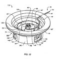
- Fig. 12 shows a front view of the fan unit 110 of Fig. 11 in which the assembly of the motor 21 is illustrated on the attached to the air guide tube 122 flange plate 38 which is connected via the retaining webs 29 'to 29 III with the air guide tube 122.
- the plate 38 is the bearing element 80, which with the Fastening elements 82 is provided.
- Fig. 12 illustrates an exemplary cable guide the connecting line 70 via the plate 38, the holder 72 and the opening 52nd
- Fig. 13 shows an embodiment of the invention, in which the suspension members 155 are formed of a hard plastic and as components of the tubular extension 150. These are arranged in the recesses 142, of which in Fig. 13 only the recesses 142 'and 142''' with the suspension members 155 'and 155 "' are visible.
- suspension members 155 are shown as hooks on which the suspension member 123 is suspended after assembly of the fan unit 110. These hooks are preferably designed as components of the carrier ring 140 such that the suspension member 123 at least partially engages in the recesses 142.
- the suspension link 123 is also suspended in retaining hooks 168 ', 168 ", 168''', 169 ', 169", 169'''. These are provided on the outer circumference of the carrier ring 140 and, for example, as components of the carrier ring 140 made of a hard plastic. In order to prevent slippage of the suspension member 123 during operation of the fan unit 110, stiffeners 143 and 145 are provided thereon, of which in Fig. 13 only the stiffening members 143 ", 143 '", 143 V, VI 143, 145', 145 ", 145 '", 145 V and 145 VI are visible.
- Fig. 14 11 shows a sectional view of the fan unit 110 in which the axial fan 120 is mounted in the vibration and noise damping device 130.
- Fig. 14 shows Fig. 14 the motor 21 with the stator assembly 37th
- Fig. 15 shows a partially cutaway perspective view of the fan unit 110th Fig. 15 illustrates on the one hand provided on the tubular extension 150, annular shoulder 49, against which the support ring 140 is applied. On the other hand clarifies Fig. 15 the suspension of the air duct 122 in the vibration and Noise-damping device 130 by the suspended in the suspension links 155 suspension member 123, with only the suspension member 155 '''is visible.
- Fig. 16 This suspension is in Fig. 16 further clarified in which was dispensed with an image of the fan 120.
- the tubular extension 150 rests against the support ring 140 and rests on this, without encasing this.
- the tubular extension 150 may be formed such that it at least partially surrounds the carrier ring 140.
- Fig. 17 shows a sectional view of the tubular extension 150, which illustrates the formed as a curved, approximately S-shaped vibration diaphragm spring element 86.
- This can alternatively like the one above Fig. 10 described modified spring element 86 'with the circumferential beads 86 "and 86''' be formed or in other, different ways, depending on which vibration behavior is required.
- Fig. 18 shows a perspective view of the support ring 60, which has a bulge 62 for guiding the connecting line 70 of Fig. 11 has
- Fig. 19 shows a perspective view of the support ring 140, which illustrates the provided therein recesses 142 'to 142''' with the hooks provided therein hook members 155 'to 155''.
- the suspension member 155 may be formed as an integral part of the first ring 140.
- the at least one suspension link 123 may be formed as an annular carrier strip which is secured to a plurality of brackets (168 ', 168 ", 168"', 169 ') provided on the air guide tube 122.
- at least a part of a suspension member 23 can engage in a lateral recess (42), in particular a suspension member can be a recess (28), which rests on the support element 55, in particular, the support element 55 may be formed as part of the tubular extension 50.
Claims (14)
- Unité de ventilation équipée d'un ventilateur axial (20 ; 120), lequel ventilateur axial comporte un tube (22 ; 122) de guidage d'air qui est qualifié de tube interne de guidage d'air, ci-après, et par l'intermédiaire duquel de l'air est acheminé en service, lequel tube interne (22 ; 122) de guidage d'air est muni d'au moins un organe de suspension (23 ; 123) en un matériau élastomère, caractérisée par le fait que ladite unité de ventilation est dotée d'un tube externe (50 ; 150) en une matière plastique tendre ou molle, relié à une première bague (40 ; 140) constituée d'une matière plastique à stabilité de forme, à l'intérieur de laquelle le tube interne (22 ; 122) de guidage d'air est fixé au moyen d'au moins un organe de suspension (23 ; 123), et qui est pourvue d'au moins un évidement latéral (42 ; 142) au niveau duquel un organe d'accrochage (55 ; 155) est prévu pour accrocher ledit au moins un organe de suspension (23 ; 123).
- Unité de ventilation selon la revendication 1, dans laquelle l'organe d'accrochage (155), prévu au minimum, est réalisé en forme de crochet,
et l'organe de suspension (123), prévu au minimum, est suspendu à cet organe d'accrochage (155). - Unité de ventilation selon la revendication 2, dans laquelle l'organe d'accrochage (55), prévu au minimum, est réalisé sous la forme d'un élément d'appui,
et l'organe de suspension (23), prévu au minimum, repose au moins en partie sur ledit élément d'appui (55). - Unité de ventilation selon l'une des revendications précédentes, dans laquelle le tube externe (50 ; 150) est réalisé à la manière d'un soufflet.
- Unité de ventilation selon l'une des revendications précédentes, dans laquelle le tube externe (50 ; 150) comporte une seconde bague (60) constituée d'une matière plastique dure, en vue de relier ce tube (50 ; 150) à une partie de support (15) avec effet d'amortissement vibratoire.
- Unité de ventilation selon la revendication 5, dans laquelle la seconde bague (60) est reliée à l'extrémité du tube externe (50 ; 150) qui est tournée vers la partie de support (15).
- Unité de ventilation selon la revendication 5 ou 6, dans laquelle la première bague (40 ; 140), le tube externe (50 ; 150) et la seconde bague (60) sont réalisés sous la forme d'un ensemble structurel unitaire par application d'une technique à composants multiples.
- Unité de ventilation selon l'une des revendications 5 à 7, dans laquelle le tube externe (50 ; 150) présente, entre la première bague (40 ; 140) et la seconde bague (60), un élément élastique (86, 86') à comportement oscillatoire préétabli, en vue d'autoriser un mouvement relatif entre ladite première bague (40 ; 140) et ladite seconde bague (60).
- Unité de ventilation selon la revendication 8, dans laquelle l'élément élastique (86) est de réalisation du type membrane.
- Unité de ventilation selon la revendication 9, dans laquelle l'élément élastique (86') est réalisé sous la forme d'un bourrelet périphérique (86", 86"') (figure 10).
- Unité de ventilation selon l'une des revendications 5 à 10, dans laquelle le tube externe (50 ; 150) est relié à la première bague (40 ; 140) et/ou à la seconde bague (60) par coulée injectée.
- Unité de ventilation selon l'une des revendications 5 à 11, dans laquelle le tube externe (50 ; 150) est relié à la première bague (40 ; 140) et/ou à la seconde bague (60) par instauration d'une liaison par coincement (figure 13).
- Unité de ventilation selon l'une des revendications 5 à 12, dans laquelle le tube externe (50 ; 150) est relié à la première bague (40 ; 140) et/ou à la seconde bague (60) par instauration d'une liaison par collage.
- Unité de ventilation selon l'une des revendications 5 à 13, dans laquelle le tube externe (50 ; 150) est relié à la première bague (40 ; 140) et/ou à la seconde bague (60) par soudage de matières plastiques.
Applications Claiming Priority (1)
| Application Number | Priority Date | Filing Date | Title |
|---|---|---|---|
| DE202008001613U DE202008001613U1 (de) | 2008-01-25 | 2008-01-25 | Lüftereinheit mit einem Axiallüfter |
Publications (2)
| Publication Number | Publication Date |
|---|---|
| EP2083176A1 EP2083176A1 (fr) | 2009-07-29 |
| EP2083176B1 true EP2083176B1 (fr) | 2010-10-20 |
Family
ID=40524544
Family Applications (1)
| Application Number | Title | Priority Date | Filing Date |
|---|---|---|---|
| EP08021713A Active EP2083176B1 (fr) | 2008-01-25 | 2008-12-15 | Unité de ventilateur dotée d'un ventilateur axial |
Country Status (4)
| Country | Link |
|---|---|
| US (1) | US8142139B2 (fr) |
| EP (1) | EP2083176B1 (fr) |
| AT (1) | ATE485453T1 (fr) |
| DE (3) | DE202008001613U1 (fr) |
Families Citing this family (90)
| Publication number | Priority date | Publication date | Assignee | Title |
|---|---|---|---|---|
| GB0814835D0 (en) * | 2007-09-04 | 2008-09-17 | Dyson Technology Ltd | A Fan |
| GB2463698B (en) * | 2008-09-23 | 2010-12-01 | Dyson Technology Ltd | A fan |
| GB2464736A (en) | 2008-10-25 | 2010-04-28 | Dyson Technology Ltd | Fan with a filter |
| GB2466058B (en) * | 2008-12-11 | 2010-12-22 | Dyson Technology Ltd | Fan nozzle with spacers |
| GB2468323A (en) | 2009-03-04 | 2010-09-08 | Dyson Technology Ltd | Fan assembly |
| KR101455224B1 (ko) | 2009-03-04 | 2014-10-31 | 다이슨 테크놀러지 리미티드 | 선풍기 |
| PL2276933T3 (pl) | 2009-03-04 | 2011-10-31 | Dyson Technology Ltd | Wentylator |
| GB2468331B (en) | 2009-03-04 | 2011-02-16 | Dyson Technology Ltd | A fan |
| AU2010219483B2 (en) | 2009-03-04 | 2011-10-13 | Dyson Technology Limited | A fan assembly |
| GB2468329A (en) | 2009-03-04 | 2010-09-08 | Dyson Technology Ltd | Fan assembly |
| GB2468312A (en) | 2009-03-04 | 2010-09-08 | Dyson Technology Ltd | Fan assembly |
| GB0903682D0 (en) | 2009-03-04 | 2009-04-15 | Dyson Technology Ltd | A fan |
| GB2468317A (en) * | 2009-03-04 | 2010-09-08 | Dyson Technology Ltd | Height adjustable and oscillating fan |
| GB2476172B (en) | 2009-03-04 | 2011-11-16 | Dyson Technology Ltd | Tilting fan stand |
| GB2468320C (en) | 2009-03-04 | 2011-06-01 | Dyson Technology Ltd | Tilting fan |
| WO2010100462A1 (fr) * | 2009-03-04 | 2010-09-10 | Dyson Technology Limited | Appareil humidificateur |
| GB2468315A (en) | 2009-03-04 | 2010-09-08 | Dyson Technology Ltd | Tilting fan |
| GB2468325A (en) * | 2009-03-04 | 2010-09-08 | Dyson Technology Ltd | Height adjustable fan with nozzle |
| GB2468326A (en) | 2009-03-04 | 2010-09-08 | Dyson Technology Ltd | Telescopic pedestal fan |
| DE102009044349A1 (de) * | 2009-10-28 | 2011-05-05 | Minebea Co., Ltd. | Lüfteranordnung |
| GB0919473D0 (en) | 2009-11-06 | 2009-12-23 | Dyson Technology Ltd | A fan |
| DE202009017511U1 (de) * | 2009-12-22 | 2011-05-05 | Ebm-Pabst Mulfingen Gmbh & Co. Kg | Lüftereinheit für Filterlüfter |
| GB2478927B (en) * | 2010-03-23 | 2016-09-14 | Dyson Technology Ltd | Portable fan with filter unit |
| GB2478925A (en) | 2010-03-23 | 2011-09-28 | Dyson Technology Ltd | External filter for a fan |
| WO2011147318A1 (fr) | 2010-05-27 | 2011-12-01 | Li Dezheng | Dispositif pour souffler de l'air au moyen d'un ensemble buse à fente étroite |
| GB2482549A (en) | 2010-08-06 | 2012-02-08 | Dyson Technology Ltd | A fan assembly with a heater |
| GB2482548A (en) | 2010-08-06 | 2012-02-08 | Dyson Technology Ltd | A fan assembly with a heater |
| GB2482547A (en) | 2010-08-06 | 2012-02-08 | Dyson Technology Ltd | A fan assembly with a heater |
| GB2483448B (en) * | 2010-09-07 | 2015-12-02 | Dyson Technology Ltd | A fan |
| DE102010045899B3 (de) * | 2010-09-17 | 2012-02-16 | Ingo Schehr | Ventilatoreinheit mit einem elektrischen Axialventilator |
| JP5588565B2 (ja) | 2010-10-13 | 2014-09-10 | ダイソン テクノロジー リミテッド | 送風機組立体 |
| GB2484670B (en) | 2010-10-18 | 2018-04-25 | Dyson Technology Ltd | A fan assembly |
| ES2619373T3 (es) | 2010-10-18 | 2017-06-26 | Dyson Technology Limited | Conjunto de ventilador |
| WO2012059730A1 (fr) | 2010-11-02 | 2012-05-10 | Dyson Technology Limited | Ensemble ventilateur |
| GB2486019B (en) | 2010-12-02 | 2013-02-20 | Dyson Technology Ltd | A fan |
| GB2493506B (en) | 2011-07-27 | 2013-09-11 | Dyson Technology Ltd | A fan assembly |
| BR112014001474A2 (pt) | 2011-07-27 | 2017-02-21 | Dyson Technology Ltd | conjunto de ventilador |
| GB201119500D0 (en) | 2011-11-11 | 2011-12-21 | Dyson Technology Ltd | A fan assembly |
| GB2496877B (en) | 2011-11-24 | 2014-05-07 | Dyson Technology Ltd | A fan assembly |
| GB2498547B (en) * | 2012-01-19 | 2015-02-18 | Dyson Technology Ltd | A fan |
| GB2499044B (en) | 2012-02-06 | 2014-03-19 | Dyson Technology Ltd | A fan |
| GB2499041A (en) | 2012-02-06 | 2013-08-07 | Dyson Technology Ltd | Bladeless fan including an ionizer |
| GB2499042A (en) | 2012-02-06 | 2013-08-07 | Dyson Technology Ltd | A nozzle for a fan assembly |
| GB2500011B (en) | 2012-03-06 | 2016-07-06 | Dyson Technology Ltd | A Humidifying Apparatus |
| GB2500017B (en) | 2012-03-06 | 2015-07-29 | Dyson Technology Ltd | A Humidifying Apparatus |
| GB2500010B (en) | 2012-03-06 | 2016-08-24 | Dyson Technology Ltd | A humidifying apparatus |
| MY167968A (en) * | 2012-03-06 | 2018-10-09 | Dyson Technology Ltd | A fan assembly |
| GB2500012B (en) | 2012-03-06 | 2016-07-06 | Dyson Technology Ltd | A Humidifying Apparatus |
| EP2822626B1 (fr) * | 2012-03-06 | 2017-09-27 | ResMed Motor Technologies Inc. | Générateur de flux |
| GB2512192B (en) | 2012-03-06 | 2015-08-05 | Dyson Technology Ltd | A Humidifying Apparatus |
| GB2500903B (en) | 2012-04-04 | 2015-06-24 | Dyson Technology Ltd | Heating apparatus |
| GB2501301B (en) | 2012-04-19 | 2016-02-03 | Dyson Technology Ltd | A fan assembly |
| GB2518935B (en) | 2012-05-16 | 2016-01-27 | Dyson Technology Ltd | A fan |
| WO2013171452A2 (fr) | 2012-05-16 | 2013-11-21 | Dyson Technology Limited | Ventilateur |
| GB2502104B (en) | 2012-05-16 | 2016-01-27 | Dyson Technology Ltd | A fan |
| DE102012209970A1 (de) | 2012-06-14 | 2013-12-19 | Krones Ag | Monotec-sternsäulen mit umluftkühler |
| GB2503907B (en) | 2012-07-11 | 2014-05-28 | Dyson Technology Ltd | A fan assembly |
| CN103790866B (zh) * | 2012-10-31 | 2016-05-11 | 英业达科技有限公司 | 风扇结构 |
| BR302013003358S1 (pt) | 2013-01-18 | 2014-11-25 | Dyson Technology Ltd | Configuração aplicada em umidificador |
| AU350179S (en) | 2013-01-18 | 2013-08-15 | Dyson Technology Ltd | Humidifier or fan |
| AU350140S (en) | 2013-01-18 | 2013-08-13 | Dyson Technology Ltd | Humidifier or fan |
| AU350181S (en) | 2013-01-18 | 2013-08-15 | Dyson Technology Ltd | Humidifier or fan |
| GB2510195B (en) | 2013-01-29 | 2016-04-27 | Dyson Technology Ltd | A fan assembly |
| RU2684043C2 (ru) | 2013-01-29 | 2019-04-03 | Дайсон Текнолоджи Лимитед | Вентилятор в сборе |
| CA152656S (en) | 2013-03-07 | 2014-05-20 | Dyson Technology Ltd | Fan |
| CA152657S (en) | 2013-03-07 | 2014-05-20 | Dyson Technology Ltd | Fan |
| BR302013004394S1 (pt) | 2013-03-07 | 2014-12-02 | Dyson Technology Ltd | Configuração aplicada a ventilador |
| USD729372S1 (en) | 2013-03-07 | 2015-05-12 | Dyson Technology Limited | Fan |
| CA152658S (en) | 2013-03-07 | 2014-05-20 | Dyson Technology Ltd | Fan |
| CA152655S (en) | 2013-03-07 | 2014-05-20 | Dyson Technology Ltd | Fan |
| DE202013101596U1 (de) | 2013-04-15 | 2013-04-24 | Elektrosil Systeme Der Elektronik Gmbh | Lüftereinheit |
| GB2516058B (en) | 2013-07-09 | 2016-12-21 | Dyson Technology Ltd | A fan assembly with an oscillation and tilt mechanism |
| CA154722S (en) | 2013-08-01 | 2015-02-16 | Dyson Technology Ltd | Fan |
| TWD172707S (zh) | 2013-08-01 | 2015-12-21 | 戴森科技有限公司 | 風扇 |
| CA154723S (en) | 2013-08-01 | 2015-02-16 | Dyson Technology Ltd | Fan |
| DE102013108827B4 (de) * | 2013-08-14 | 2021-07-22 | Ebm-Papst St. Georgen Gmbh & Co. Kg | Lüftereinheit mit einem Axiallüfter |
| GB2518638B (en) | 2013-09-26 | 2016-10-12 | Dyson Technology Ltd | Humidifying apparatus |
| JP2015151925A (ja) * | 2014-02-14 | 2015-08-24 | 株式会社デンソー | 送風装置 |
| GB2528708B (en) | 2014-07-29 | 2016-06-29 | Dyson Technology Ltd | A fan assembly |
| GB2528704A (en) | 2014-07-29 | 2016-02-03 | Dyson Technology Ltd | Humidifying apparatus |
| GB2528709B (en) | 2014-07-29 | 2017-02-08 | Dyson Technology Ltd | Humidifying apparatus |
| DE102014111055A1 (de) * | 2014-08-04 | 2016-02-04 | Ebm-Papst St. Georgen Gmbh & Co. Kg | Lüftereinheit mit einem Axiallüfter |
| DE102015211116A1 (de) * | 2015-06-17 | 2016-12-22 | Volkswagen Aktiengesellschaft | Verfahren und Vorrichtung zum Betreiben einer Sitzbelüftungseinrichtung, Sitzbelüftungseinrichtung |
| FR3047123A1 (fr) * | 2016-01-26 | 2017-07-28 | Valeo Systemes Thermiques | Ensemble de support d'un moteur electrique, notamment dans un dispositif de chauffage, ventilation et/ou climatisation pour vehicule automobile |
| DE202016103052U1 (de) | 2016-06-08 | 2017-03-28 | Elektrosil Systeme Der Elektronik Gmbh | Lüftereinheit mit mehreren zwischen Luftführungsrohr und Lüftergitter angeordneten Dämpfungselementen |
| JP1581993S (fr) * | 2016-11-29 | 2017-07-24 | ||
| USD909559S1 (en) * | 2019-01-09 | 2021-02-02 | Rodney James Harman | Grille for air duct |
| US10837461B2 (en) * | 2019-04-10 | 2020-11-17 | Haier Us Appliance Solutions, Inc. | Vibration isolating mounting of fan |
| CN114526267B (zh) * | 2020-11-23 | 2024-01-30 | 广东美的白色家电技术创新中心有限公司 | 风机和油烟机 |
| CN214145996U (zh) * | 2021-01-13 | 2021-09-07 | 北京小米移动软件有限公司 | 一种空调贯流风扇用旋转轴套及空调 |
Family Cites Families (13)
| Publication number | Priority date | Publication date | Assignee | Title |
|---|---|---|---|---|
| US3820916A (en) * | 1972-05-12 | 1974-06-28 | I Brusilovsky | Axial flow reversible fan |
| US4568243A (en) | 1981-10-08 | 1986-02-04 | Barry Wright Corporation | Vibration isolating seal for mounting fans and blowers |
| US4908929A (en) | 1987-12-22 | 1990-03-20 | The United States Of America As Represented By The Secretary Of The Navy | Fabrication of low frequency structureborne vibration isolation mount |
| SE469041B (sv) * | 1991-08-16 | 1993-05-03 | Nokia Data Ab | Anordning foer uppbaerande av ett flaekthus med hjaelp av en elastisk ring |
| DE19746185B4 (de) * | 1997-10-18 | 2013-04-11 | Behr Gmbh & Co. Kg | Halter für einen Elektromotor, insbesondere für einen Gebläsemotor einer Lüftungs-, Heizungs- oder Klimaanlage eines Kraftfahrzeuges |
| US7409111B2 (en) * | 1997-10-21 | 2008-08-05 | Canon Kabushiki Kaisha | Image synthesizing system for automatically retrieving and synthesizing images to be synthesized |
| DE29914693U1 (de) * | 1998-09-01 | 2000-01-13 | Papst Motoren Gmbh & Co Kg | Axiallüfter mit einem Aussenläufer-Antriebsmotor |
| US6616094B2 (en) * | 1999-05-21 | 2003-09-09 | Vortex Holding Company | Lifting platform |
| EP1498613B1 (fr) * | 2003-07-15 | 2010-05-19 | EMB-Papst St. Georgen GmbH & Co. KG | Ensemble ventilateur et sa méthode de fabrication |
| DE202005011514U1 (de) * | 2005-07-19 | 2005-10-13 | Arctic-Cooling Switzerland Ag | Ventilator für Computer |
| DE102005051853B3 (de) * | 2005-10-28 | 2007-06-06 | Fujitsu Siemens Computers Gmbh | Lüfteranordnung |
| DE102006004465B4 (de) * | 2006-01-30 | 2008-10-30 | I.G. Bauerhin Gmbh | Einlegerteil für einen klimatisierten Fahrzeugsitz, Baugruppe mit mindestens zwei Einlegerteilen, Fahrzeugsitz, der ein solches Einlegerteil oder eine solche Baugruppe aufweist |
| JP4967773B2 (ja) * | 2007-04-12 | 2012-07-04 | ソニー株式会社 | 投射型表示装置 |
-
2008
- 2008-01-25 DE DE202008001613U patent/DE202008001613U1/de not_active Expired - Lifetime
- 2008-12-15 US US12/334,558 patent/US8142139B2/en active Active
- 2008-12-15 EP EP08021713A patent/EP2083176B1/fr active Active
- 2008-12-15 DE DE502008001580T patent/DE502008001580D1/de active Active
- 2008-12-15 AT AT08021713T patent/ATE485453T1/de active
-
2009
- 2009-01-21 DE DE102009005383A patent/DE102009005383A1/de not_active Ceased
Also Published As
| Publication number | Publication date |
|---|---|
| ATE485453T1 (de) | 2010-11-15 |
| US8142139B2 (en) | 2012-03-27 |
| EP2083176A1 (fr) | 2009-07-29 |
| DE102009005383A1 (de) | 2009-07-30 |
| US20090191054A1 (en) | 2009-07-30 |
| DE502008001580D1 (de) | 2010-12-02 |
| DE202008001613U1 (de) | 2009-06-10 |
Similar Documents
| Publication | Publication Date | Title |
|---|---|---|
| EP2083176B1 (fr) | Unité de ventilateur dotée d'un ventilateur axial | |
| EP1498613B1 (fr) | Ensemble ventilateur et sa méthode de fabrication | |
| DE19712228B4 (de) | Befestigungsvorrichtung für einen Gebläsemotor | |
| EP0642206B2 (fr) | Support pour un moteur électrique, en particulier pour un ventilateur d'un appareil de chauffage ou de climatisation | |
| DE69722828T2 (de) | Gebläserad mit axiallufteinlassöffnung | |
| DE2515234C3 (de) | Halter zum schwingungsdämpfenden Befestigen eines Mikrophons im Inneren eines elektrischen Gerätes | |
| DE102009044349A1 (de) | Lüfteranordnung | |
| EP0135845B1 (fr) | Moyens de montage d'un appareil pourvu de deux brides successives de support | |
| EP2112381A2 (fr) | Dispositif ventilateur | |
| EP1813471A2 (fr) | Partie d'insertion pour un siège climatisé, module doté d'au moins deux parties d'insertion, siège de véhicule automobile, comprenant une telle partie d'insertion ou un tel module | |
| EP1447898A1 (fr) | Moteur à rotor extérieur | |
| WO2016096170A1 (fr) | Dispositif de ventilation d'un siège de véhicule et siège de véhicule | |
| DE202005011514U1 (de) | Ventilator für Computer | |
| DE19651735A1 (de) | Halterung für einen Motor, insbesondere einen Gebläserad-Elektromotor | |
| DE10058935A1 (de) | Vorrichtung zur Befestigung einer Ventilatorschraube an einer Antriebswelle | |
| DE102013107579A1 (de) | Ventilator für gasförmige Medien | |
| EP0696833B1 (fr) | Dispositif de fixation insonorisant pour moteur notamment pour positionneurs électriques de véhicules | |
| DE202006019690U1 (de) | Luftdurchtrittsvorrichtung | |
| DE202014010370U1 (de) | Lüftereinheit mit einem Lüftergehäuse | |
| EP3116106A1 (fr) | Machine électrique avec insonorisation | |
| DE10109621B4 (de) | Serieller Lüfter | |
| EP2467606B1 (fr) | Découplage vibratoire d'un moteur d'entraînement | |
| DE102014105876A1 (de) | Motorlagerung für einen Motor, insbesondere eines Ventilators eines Fahrzeugklimageräts | |
| EP2381112A2 (fr) | Ventilateur axial | |
| EP3976971A1 (fr) | Dispositif de refroidissement |
Legal Events
| Date | Code | Title | Description |
|---|---|---|---|
| PUAI | Public reference made under article 153(3) epc to a published international application that has entered the european phase |
Free format text: ORIGINAL CODE: 0009012 |
|
| AK | Designated contracting states |
Kind code of ref document: A1 Designated state(s): AT BE BG CH CY CZ DE DK EE ES FI FR GB GR HR HU IE IS IT LI LT LU LV MC MT NL NO PL PT RO SE SI SK TR |
|
| AX | Request for extension of the european patent |
Extension state: AL BA MK RS |
|
| 17P | Request for examination filed |
Effective date: 20090904 |
|
| 17Q | First examination report despatched |
Effective date: 20091130 |
|
| AKX | Designation fees paid |
Designated state(s): AT BE BG CH CY CZ DE DK EE ES FI FR GB GR HR HU IE IS IT LI LT LU LV MC MT NL NO PL PT RO SE SI SK TR |
|
| GRAP | Despatch of communication of intention to grant a patent |
Free format text: ORIGINAL CODE: EPIDOSNIGR1 |
|
| GRAS | Grant fee paid |
Free format text: ORIGINAL CODE: EPIDOSNIGR3 |
|
| GRAA | (expected) grant |
Free format text: ORIGINAL CODE: 0009210 |
|
| AK | Designated contracting states |
Kind code of ref document: B1 Designated state(s): AT BE BG CH CY CZ DE DK EE ES FI FR GB GR HR HU IE IS IT LI LT LU LV MC MT NL NO PL PT RO SE SI SK TR |
|
| REG | Reference to a national code |
Ref country code: GB Ref legal event code: FG4D Free format text: NOT ENGLISH |
|
| REG | Reference to a national code |
Ref country code: CH Ref legal event code: EP |
|
| REG | Reference to a national code |
Ref country code: IE Ref legal event code: FG4D Free format text: LANGUAGE OF EP DOCUMENT: GERMAN |
|
| REF | Corresponds to: |
Ref document number: 502008001580 Country of ref document: DE Date of ref document: 20101202 Kind code of ref document: P |
|
| REG | Reference to a national code |
Ref country code: NL Ref legal event code: VDEP Effective date: 20101020 |
|
| LTIE | Lt: invalidation of european patent or patent extension |
Effective date: 20101020 |
|
| PG25 | Lapsed in a contracting state [announced via postgrant information from national office to epo] |
Ref country code: LT Free format text: LAPSE BECAUSE OF FAILURE TO SUBMIT A TRANSLATION OF THE DESCRIPTION OR TO PAY THE FEE WITHIN THE PRESCRIBED TIME-LIMIT Effective date: 20101020 Ref country code: NO Free format text: LAPSE BECAUSE OF FAILURE TO SUBMIT A TRANSLATION OF THE DESCRIPTION OR TO PAY THE FEE WITHIN THE PRESCRIBED TIME-LIMIT Effective date: 20110120 |
|
| REG | Reference to a national code |
Ref country code: IE Ref legal event code: FD4D |
|
| PG25 | Lapsed in a contracting state [announced via postgrant information from national office to epo] |
Ref country code: SI Free format text: LAPSE BECAUSE OF FAILURE TO SUBMIT A TRANSLATION OF THE DESCRIPTION OR TO PAY THE FEE WITHIN THE PRESCRIBED TIME-LIMIT Effective date: 20101020 Ref country code: LV Free format text: LAPSE BECAUSE OF FAILURE TO SUBMIT A TRANSLATION OF THE DESCRIPTION OR TO PAY THE FEE WITHIN THE PRESCRIBED TIME-LIMIT Effective date: 20101020 Ref country code: HR Free format text: LAPSE BECAUSE OF FAILURE TO SUBMIT A TRANSLATION OF THE DESCRIPTION OR TO PAY THE FEE WITHIN THE PRESCRIBED TIME-LIMIT Effective date: 20101020 Ref country code: NL Free format text: LAPSE BECAUSE OF FAILURE TO SUBMIT A TRANSLATION OF THE DESCRIPTION OR TO PAY THE FEE WITHIN THE PRESCRIBED TIME-LIMIT Effective date: 20101020 Ref country code: PT Free format text: LAPSE BECAUSE OF FAILURE TO SUBMIT A TRANSLATION OF THE DESCRIPTION OR TO PAY THE FEE WITHIN THE PRESCRIBED TIME-LIMIT Effective date: 20110221 Ref country code: BG Free format text: LAPSE BECAUSE OF FAILURE TO SUBMIT A TRANSLATION OF THE DESCRIPTION OR TO PAY THE FEE WITHIN THE PRESCRIBED TIME-LIMIT Effective date: 20110120 Ref country code: SE Free format text: LAPSE BECAUSE OF FAILURE TO SUBMIT A TRANSLATION OF THE DESCRIPTION OR TO PAY THE FEE WITHIN THE PRESCRIBED TIME-LIMIT Effective date: 20101020 Ref country code: IS Free format text: LAPSE BECAUSE OF FAILURE TO SUBMIT A TRANSLATION OF THE DESCRIPTION OR TO PAY THE FEE WITHIN THE PRESCRIBED TIME-LIMIT Effective date: 20110220 Ref country code: FI Free format text: LAPSE BECAUSE OF FAILURE TO SUBMIT A TRANSLATION OF THE DESCRIPTION OR TO PAY THE FEE WITHIN THE PRESCRIBED TIME-LIMIT Effective date: 20101020 |
|
| BERE | Be: lapsed |
Owner name: EBM-PAPST ST. GEORGEN G.M.B.H. & CO. KG Effective date: 20101231 |
|
| PG25 | Lapsed in a contracting state [announced via postgrant information from national office to epo] |
Ref country code: GR Free format text: LAPSE BECAUSE OF FAILURE TO SUBMIT A TRANSLATION OF THE DESCRIPTION OR TO PAY THE FEE WITHIN THE PRESCRIBED TIME-LIMIT Effective date: 20110121 |
|
| PG25 | Lapsed in a contracting state [announced via postgrant information from national office to epo] |
Ref country code: MC Free format text: LAPSE BECAUSE OF NON-PAYMENT OF DUE FEES Effective date: 20101231 Ref country code: CZ Free format text: LAPSE BECAUSE OF FAILURE TO SUBMIT A TRANSLATION OF THE DESCRIPTION OR TO PAY THE FEE WITHIN THE PRESCRIBED TIME-LIMIT Effective date: 20101020 Ref country code: ES Free format text: LAPSE BECAUSE OF FAILURE TO SUBMIT A TRANSLATION OF THE DESCRIPTION OR TO PAY THE FEE WITHIN THE PRESCRIBED TIME-LIMIT Effective date: 20110131 Ref country code: IE Free format text: LAPSE BECAUSE OF FAILURE TO SUBMIT A TRANSLATION OF THE DESCRIPTION OR TO PAY THE FEE WITHIN THE PRESCRIBED TIME-LIMIT Effective date: 20101020 Ref country code: EE Free format text: LAPSE BECAUSE OF FAILURE TO SUBMIT A TRANSLATION OF THE DESCRIPTION OR TO PAY THE FEE WITHIN THE PRESCRIBED TIME-LIMIT Effective date: 20101020 |
|
| PLBE | No opposition filed within time limit |
Free format text: ORIGINAL CODE: 0009261 |
|
| STAA | Information on the status of an ep patent application or granted ep patent |
Free format text: STATUS: NO OPPOSITION FILED WITHIN TIME LIMIT |
|
| PG25 | Lapsed in a contracting state [announced via postgrant information from national office to epo] |
Ref country code: PL Free format text: LAPSE BECAUSE OF FAILURE TO SUBMIT A TRANSLATION OF THE DESCRIPTION OR TO PAY THE FEE WITHIN THE PRESCRIBED TIME-LIMIT Effective date: 20101020 Ref country code: RO Free format text: LAPSE BECAUSE OF FAILURE TO SUBMIT A TRANSLATION OF THE DESCRIPTION OR TO PAY THE FEE WITHIN THE PRESCRIBED TIME-LIMIT Effective date: 20101020 Ref country code: SK Free format text: LAPSE BECAUSE OF FAILURE TO SUBMIT A TRANSLATION OF THE DESCRIPTION OR TO PAY THE FEE WITHIN THE PRESCRIBED TIME-LIMIT Effective date: 20101020 Ref country code: DK Free format text: LAPSE BECAUSE OF FAILURE TO SUBMIT A TRANSLATION OF THE DESCRIPTION OR TO PAY THE FEE WITHIN THE PRESCRIBED TIME-LIMIT Effective date: 20101020 |
|
| 26N | No opposition filed |
Effective date: 20110721 |
|
| PG25 | Lapsed in a contracting state [announced via postgrant information from national office to epo] |
Ref country code: BE Free format text: LAPSE BECAUSE OF NON-PAYMENT OF DUE FEES Effective date: 20101231 |
|
| REG | Reference to a national code |
Ref country code: DE Ref legal event code: R097 Ref document number: 502008001580 Country of ref document: DE Effective date: 20110721 |
|
| PG25 | Lapsed in a contracting state [announced via postgrant information from national office to epo] |
Ref country code: MT Free format text: LAPSE BECAUSE OF FAILURE TO SUBMIT A TRANSLATION OF THE DESCRIPTION OR TO PAY THE FEE WITHIN THE PRESCRIBED TIME-LIMIT Effective date: 20101020 |
|
| PG25 | Lapsed in a contracting state [announced via postgrant information from national office to epo] |
Ref country code: CY Free format text: LAPSE BECAUSE OF FAILURE TO SUBMIT A TRANSLATION OF THE DESCRIPTION OR TO PAY THE FEE WITHIN THE PRESCRIBED TIME-LIMIT Effective date: 20101020 |
|
| PG25 | Lapsed in a contracting state [announced via postgrant information from national office to epo] |
Ref country code: LU Free format text: LAPSE BECAUSE OF NON-PAYMENT OF DUE FEES Effective date: 20101215 Ref country code: HU Free format text: LAPSE BECAUSE OF FAILURE TO SUBMIT A TRANSLATION OF THE DESCRIPTION OR TO PAY THE FEE WITHIN THE PRESCRIBED TIME-LIMIT Effective date: 20110421 |
|
| PG25 | Lapsed in a contracting state [announced via postgrant information from national office to epo] |
Ref country code: TR Free format text: LAPSE BECAUSE OF FAILURE TO SUBMIT A TRANSLATION OF THE DESCRIPTION OR TO PAY THE FEE WITHIN THE PRESCRIBED TIME-LIMIT Effective date: 20101020 |
|
| REG | Reference to a national code |
Ref country code: CH Ref legal event code: PL |
|
| GBPC | Gb: european patent ceased through non-payment of renewal fee |
Effective date: 20121215 |
|
| PG25 | Lapsed in a contracting state [announced via postgrant information from national office to epo] |
Ref country code: CH Free format text: LAPSE BECAUSE OF NON-PAYMENT OF DUE FEES Effective date: 20121231 Ref country code: LI Free format text: LAPSE BECAUSE OF NON-PAYMENT OF DUE FEES Effective date: 20121231 |
|
| PG25 | Lapsed in a contracting state [announced via postgrant information from national office to epo] |
Ref country code: GB Free format text: LAPSE BECAUSE OF NON-PAYMENT OF DUE FEES Effective date: 20121215 |
|
| REG | Reference to a national code |
Ref country code: AT Ref legal event code: MM01 Ref document number: 485453 Country of ref document: AT Kind code of ref document: T Effective date: 20131215 |
|
| PG25 | Lapsed in a contracting state [announced via postgrant information from national office to epo] |
Ref country code: AT Free format text: LAPSE BECAUSE OF NON-PAYMENT OF DUE FEES Effective date: 20131215 |
|
| REG | Reference to a national code |
Ref country code: FR Ref legal event code: PLFP Year of fee payment: 8 |
|
| REG | Reference to a national code |
Ref country code: FR Ref legal event code: PLFP Year of fee payment: 9 |
|
| REG | Reference to a national code |
Ref country code: FR Ref legal event code: PLFP Year of fee payment: 10 |
|
| PGFP | Annual fee paid to national office [announced via postgrant information from national office to epo] |
Ref country code: IT Payment date: 20221230 Year of fee payment: 15 |
|
| PGFP | Annual fee paid to national office [announced via postgrant information from national office to epo] |
Ref country code: FR Payment date: 20231219 Year of fee payment: 16 Ref country code: DE Payment date: 20231214 Year of fee payment: 16 |