EP2083176B1 - Ventilation unit with an axial ventilator - Google Patents
Ventilation unit with an axial ventilator Download PDFInfo
- Publication number
- EP2083176B1 EP2083176B1 EP08021713A EP08021713A EP2083176B1 EP 2083176 B1 EP2083176 B1 EP 2083176B1 EP 08021713 A EP08021713 A EP 08021713A EP 08021713 A EP08021713 A EP 08021713A EP 2083176 B1 EP2083176 B1 EP 2083176B1
- Authority
- EP
- European Patent Office
- Prior art keywords
- ring
- fan unit
- unit according
- fan
- external tube
- Prior art date
- Legal status (The legal status is an assumption and is not a legal conclusion. Google has not performed a legal analysis and makes no representation as to the accuracy of the status listed.)
- Active
Links
- 238000009423 ventilation Methods 0.000 title description 2
- 239000004033 plastic Substances 0.000 claims abstract description 18
- 229920003023 plastic Polymers 0.000 claims abstract description 18
- 239000000725 suspension Substances 0.000 claims description 51
- 238000005516 engineering process Methods 0.000 claims description 5
- 239000011324 bead Substances 0.000 claims description 4
- 239000013536 elastomeric material Substances 0.000 claims description 4
- 230000010355 oscillation Effects 0.000 claims description 4
- 239000000853 adhesive Substances 0.000 claims description 2
- 230000001070 adhesive effect Effects 0.000 claims description 2
- 238000010276 construction Methods 0.000 claims description 2
- 238000001746 injection moulding Methods 0.000 claims description 2
- 238000004023 plastic welding Methods 0.000 claims description 2
- 230000002093 peripheral effect Effects 0.000 claims 1
- 238000013016 damping Methods 0.000 abstract description 19
- 229920001971 elastomer Polymers 0.000 abstract description 5
- 230000032258 transport Effects 0.000 abstract description 2
- 239000000806 elastomer Substances 0.000 abstract 1
- 239000000463 material Substances 0.000 abstract 1
- 239000012528 membrane Substances 0.000 description 4
- 230000000284 resting effect Effects 0.000 description 3
- 238000011161 development Methods 0.000 description 2
- 230000018109 developmental process Effects 0.000 description 2
- 239000002184 metal Substances 0.000 description 2
- 238000012986 modification Methods 0.000 description 2
- 230000004048 modification Effects 0.000 description 2
- 229920000642 polymer Polymers 0.000 description 2
- 239000007779 soft material Substances 0.000 description 2
- 230000005540 biological transmission Effects 0.000 description 1
- 230000001419 dependent effect Effects 0.000 description 1
- 239000006260 foam Substances 0.000 description 1
- 229920001821 foam rubber Polymers 0.000 description 1
- 238000010438 heat treatment Methods 0.000 description 1
- 238000004519 manufacturing process Methods 0.000 description 1
- 229920002635 polyurethane Polymers 0.000 description 1
- 239000004814 polyurethane Substances 0.000 description 1
- 239000003351 stiffener Substances 0.000 description 1
Images


Classifications
-
- F—MECHANICAL ENGINEERING; LIGHTING; HEATING; WEAPONS; BLASTING
- F04—POSITIVE - DISPLACEMENT MACHINES FOR LIQUIDS; PUMPS FOR LIQUIDS OR ELASTIC FLUIDS
- F04D—NON-POSITIVE-DISPLACEMENT PUMPS
- F04D29/00—Details, component parts, or accessories
- F04D29/40—Casings; Connections of working fluid
- F04D29/52—Casings; Connections of working fluid for axial pumps
- F04D29/522—Casings; Connections of working fluid for axial pumps especially adapted for elastic fluid pumps
- F04D29/526—Details of the casing section radially opposing blade tips
-
- F—MECHANICAL ENGINEERING; LIGHTING; HEATING; WEAPONS; BLASTING
- F04—POSITIVE - DISPLACEMENT MACHINES FOR LIQUIDS; PUMPS FOR LIQUIDS OR ELASTIC FLUIDS
- F04D—NON-POSITIVE-DISPLACEMENT PUMPS
- F04D29/00—Details, component parts, or accessories
- F04D29/66—Combating cavitation, whirls, noise, vibration or the like; Balancing
- F04D29/661—Combating cavitation, whirls, noise, vibration or the like; Balancing especially adapted for elastic fluid pumps
- F04D29/668—Combating cavitation, whirls, noise, vibration or the like; Balancing especially adapted for elastic fluid pumps damping or preventing mechanical vibrations
-
- F—MECHANICAL ENGINEERING; LIGHTING; HEATING; WEAPONS; BLASTING
- F16—ENGINEERING ELEMENTS AND UNITS; GENERAL MEASURES FOR PRODUCING AND MAINTAINING EFFECTIVE FUNCTIONING OF MACHINES OR INSTALLATIONS; THERMAL INSULATION IN GENERAL
- F16F—SPRINGS; SHOCK-ABSORBERS; MEANS FOR DAMPING VIBRATION
- F16F15/00—Suppression of vibrations in systems; Means or arrangements for avoiding or reducing out-of-balance forces, e.g. due to motion
- F16F15/02—Suppression of vibrations of non-rotating, e.g. reciprocating systems; Suppression of vibrations of rotating systems by use of members not moving with the rotating systems
- F16F15/04—Suppression of vibrations of non-rotating, e.g. reciprocating systems; Suppression of vibrations of rotating systems by use of members not moving with the rotating systems using elastic means
- F16F15/08—Suppression of vibrations of non-rotating, e.g. reciprocating systems; Suppression of vibrations of rotating systems by use of members not moving with the rotating systems using elastic means with rubber springs ; with springs made of rubber and metal
Landscapes
- Engineering & Computer Science (AREA)
- General Engineering & Computer Science (AREA)
- Mechanical Engineering (AREA)
- Chemical & Material Sciences (AREA)
- Combustion & Propulsion (AREA)
- Physics & Mathematics (AREA)
- Acoustics & Sound (AREA)
- Aviation & Aerospace Engineering (AREA)
- Structures Of Non-Positive Displacement Pumps (AREA)
- Motor Or Generator Cooling System (AREA)
- Cookers (AREA)
- Pipe Accessories (AREA)
Abstract
Description
Die Erfindung betrifft eine Lüftereinheit mit einem Axiallüfter.The invention relates to a fan unit with an axial fan.
Axiallüfter, und Lüfter im Allgemeinen, weisen üblicherweise eine herstellungsbedingte Unwucht auf, welche in deren Betrieb zu unerwünschten Vibrationen führen kann. Auch können durch Motor- und Luftströmungsgeräusche der Lüfter im Betrieb störende Geräusche entstehen. Derartige Vibrationen und störende Geräusche müssen besonders in Komfortanwendungen gedämpft werden.Axial fans, and fans in general, usually have a production-related imbalance, which in their operation can lead to unwanted vibrations. Also, engine and airflow noise may cause the fan to interfere with noise during operation. Such vibrations and disturbing noises must be damped especially in comfort applications.
Die
Bei einer anderen Ausführungsform ist statt der Gummischnüre ein konisches Teil aus Polyurethan vorgesehen, wodurch die Luftverluste verringert werden und der Wirkungsgrad verbessert wird.In another embodiment, instead of the rubber cords, a conical part made of polyurethane is provided, whereby the air losses are reduced and the efficiency is improved.
Aus der
Die
Es ist deshalb eine Aufgabe der Erfindung, eine neue Lüftereinheit mit einem Axiallüfter bereit zu stellen. Diese Aufgabe wird gelöst durch eine Lüftereinheit gemäß Anspruch 1. Hierbei erreicht man einen sehr kompakten Aufbau bei verbesserter Vibrations- und Geräuschdämpfung.It is therefore an object of the invention to provide a new fan unit with an axial fan. This object is achieved by a fan unit according to claim 1. This achieves a very compact design with improved vibration and noise damping.
Bevorzugte Weiterbildungen sind Gegenstand von Unteransprüchen.Preferred developments are the subject of dependent claims.
Weitere Einzelheiten und vorteilhafte Weiterbildungen der Erfindung ergeben sich aus den im folgenden beschriebenen und in den Zeichnungen dargestellten, in keiner Weise als Einschränkung der Erfindung zu verstehenden Ausführungsbeispielen. Es zeigt:
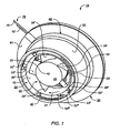
- Fig. 1
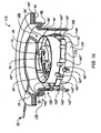
- eine perspektivische Ansicht der Rückseite einer Lüftereinheit mit Axiallüfter gemäß einer ersten Ausführungsform,
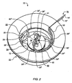
- Fig. 2
- eine perspektivische Ansicht der Vorderseite der Lüftereinheit von
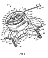
Fig. 1 , - Fig. 3
- eine teilweise geschnittene Explosionsdarstellung der Lüftereinheit von
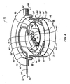
Fig. 1 , - Fig. 4
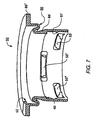
- eine teilweise geschnittene, perspektivische Ansicht der Lüftereinheit von
Fig. 1 , - Fig. 5
- eine Schnittansicht der Lüftereinheit von
Fig. 1 , - Fig. 6
- eine Schnittansicht des mit einem
Trägerring 40 verbundenen Faltenbalgs vonFig. 1 , - Fig. 7
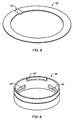
- eine Schnittansicht des Faltenbalgs von
Fig. 1 , - Fig. 8
- eine perspektivische Ansicht des Stützrings 60 von
Fig. 1 , - Fig. 9
- eine perspektivische Ansicht des
Trägerrings 40 vonFig. 1 , - Fig. 10
- eine Schnittansicht einer alternativen Ausführungsform des Faltenbalgs von
Fig. 7 , - Fig. 11
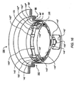
- eine perspektivische Ansicht einer Rückseite einer Lüftereinheit mit Axiallüfter gemäß einer zweiten Ausführungsform,
- Fig. 12
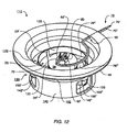
- eine perspektivische Ansicht der Vorderseite der Lüftereinheit von
Fig. 11 , - Fig. 13
- eine teilweise geschnittene Explosionsdarstellung der Lüftereinheit von
Fig. 11 , - Fig. 14
- eine Schnittansicht der Lüftereinheit von
Fig. 11 , - Fig. 15
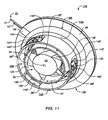
- eine teilweise geschnittene, perspektivische Ansicht der Lüftereinheit von
Fig. 11 , - Fig. 16
- eine teilweise geschnittene, perspektivische Ansicht des mit dem Trägerring verbundenen Faltenbalgs von
Fig. 11 , - Fig. 17
- eine Schnittansicht des Faltenbalgs von
Fig. 11 , - Fig. 18
- eine perspektivische Ansicht des Stützrings 60 von
Fig. 11 , und - Fig. 19
- eine perspektivische Ansicht des
Trägerrings 140 vonFig. 11 .
- Fig. 1
- a perspective view of the back of a fan unit with axial fan according to a first embodiment,
- Fig. 2
- a perspective view of the front of the fan unit of
Fig. 1 . - Fig. 3
- a partially sectioned exploded view of the fan unit of
Fig. 1 . - Fig. 4
- a partially sectioned, perspective view of the fan unit of
Fig. 1 . - Fig. 5
- a sectional view of the fan unit of
Fig. 1 . - Fig. 6
- a sectional view of the connected to a
support ring 40 bellows ofFig. 1 . - Fig. 7
- a sectional view of the bellows of
Fig. 1 . - Fig. 8
- a perspective view of the
support ring 60 ofFig. 1 . - Fig. 9
- a perspective view of the
carrier ring 40 ofFig. 1 . - Fig. 10
- a sectional view of an alternative embodiment of the bellows of
Fig. 7 . - Fig. 11
- 3 is a perspective view of a rear side of a fan unit with axial fan according to a second embodiment,
- Fig. 12
- a perspective view of the front of the fan unit of
Fig. 11 . - Fig. 13
- a partially sectioned exploded view of the fan unit of
Fig. 11 . - Fig. 14
- a sectional view of the fan unit of
Fig. 11 . - Fig. 15
- a partially sectioned, perspective view of the fan unit of
Fig. 11 . - Fig. 16
- a partially cut, perspective view of the support ring connected to the bellows of
Fig. 11 . - Fig. 17
- a sectional view of the bellows of
Fig. 11 . - Fig. 18
- a perspective view of the
support ring 60 ofFig. 11 , and - Fig. 19
- a perspective view of the
carrier ring 140 ofFig. 11 ,
In der nachfolgenden Beschreibung beziehen sich die Begriffe links, rechts, vorne, hinten, oben und unten auf die jeweilige Zeichnungsfigur und können in Abhängigkeit von einer jeweils gewählten Ausrichtung (Hochformat oder Querformat) von einer Zeichnungsfigur zur nächsten variieren. Gleiche oder gleich wirkende Teile werden in den verschiedenen Figuren mit denselben Bezugszeichen bezeichnet und gewöhnlich nur einmal beschrieben.In the following description, the terms left, right, front, back, top, and bottom refer to the respective drawing figure and may vary from one drawing figure to another depending on a particular orientation (portrait or landscape). Identical or equivalent parts are denoted by the same reference numerals in the various figures and usually described only once.
Der Lüfter 20 hat einen Motor 21 (
Der Motor 21 ist mit einer flexiblen elektrischen Anschlussleitung 70 verbunden. Diese ist an einer Leiterplatte 90 (
Wie aus
Gemäß einer bevorzugten Ausführungsform sind der Trägerring 40, der rohrartige Fortsatz 50 und der Stützring 60 als bauliche Einheit in Mehrkomponententechnik ausgebildet, insbesondere in 2K-Technik (2K = 2 Kunststoffe). Hierbei sind der Trägerring 40 und der Stützring 60 bevorzugt aus einem harten Kunststoff und der rohrartige Fortsatz 50 aus einem weichen Werkstoff ausgebildet. Der rohrartige Fortsatz 50 kann beispielsweise durch Spritzguss, eine Klemmverbindung, eine Klebeverbindung oder Kunststoffschweißen mit dem Trägerring 40 und/oder dem Stützring 60 verbunden werden.According to a preferred embodiment, the
Am Trägerring 40 sind zum Einhängen der Aufhängeglieder 23 mehrere Einhängeglieder 55 aus einem harten Kunststoff vorgesehen, von denen in
Im Betrieb des Axiallüfters 20 treibt der Motor 21 das Lüfterrad 24 derart an, dass dieses sich zur Erzeugung eines Luftstroms um seine Drehachse 23 dreht, beispielsweise in Richtung eines Pfeils 27 (
In
Die als Auflageelemente ausgebildeten Einhängeglieder 55 sind mit nutenförmigen Aussparungen 28 und verstärkten Seitenbereichen 31 bzw. 33 ausgebildet. Z.B. hat das Auflageelement 23VI eine nutenförmige Aussparung 28VI und verstärkte Seitenbereiche 31VI und 33VI.Trained as
Wie aus
Darüber hinaus zeigt
Insbesondere verdeutlicht
Die
Der Axiallüfter 120 von
An dem Fortsatz 150 ist das Federelement 86 (
Am Trägerring 140 sind zum Einhängen des Aufhängeglieds 123 mehrere Einhängeglieder 155' bis 155''' (nachfolgend auch als die Einhängeglieder 155 bezeichnet) aus einem harten Kunststoff vorgesehen, die in hierfür vorgesehenen seitlichen Ausnehmungen 142' bis 142''' (nachfolgend auch als die Ausnehmungen 142 bezeichnet) angeordnet sind. Das Aufhängeglied 123 ist als ringförmiges Trägerband ausgebildet, wie bei den
In
Das Aufhängeglied 123 ist ebenfalls in Haltehaken 168', 168", 168''', 169', 169", 169''' eingehängt. Diese sind am Außenumfang des Trägerrings 140 vorgesehen und z.B. als Bestandteile des Trägerrings 140 aus einem harten Kunststoff hergestellt. Um ein Verrutschen des Aufhängeglieds 123 im Betrieb der Lüftereinheit 110 zu verhindern, sind an diesem Versteifungsglieder 143 und 145 vorgesehen, von denen in
Diese Aufhängung wird in
Naturgemäß sind im Rahmen der vorliegenden Erfindung vielfache Abwandlungen und Modifikationen möglich.Naturally, many modifications and modifications are possible within the scope of the present invention.
Insbesondere kann in einer Lüftereinheit nach Anspruch 14 das Einhängeglied 155 als integraler Bestandteil des ersten Rings 140 ausgebildet sein. In einer Lüftereinheit nach Anspruch 13 oder 14 oder nach dem vorhergehenden Satz kann das mindestens eine Aufhängeglied 123 als ringförmiges Trägerband ausgebildet sein, welches an einer Mehrzahl von an dem Luftführungsrohr 122 vorgesehenen Halterungen (168', 168", 168"', 169', 169", 169''') befestigt ist. Bei einer Lüftereinheit nach Anspruch 15 kann zumindest ein Teil eines Aufhängeglieds 23 in eine seitliche Ausnehmung (42) eingreifen, insbesondere kann ein Aufhängeglied eine Aussparung (28) aufweisen, welche auf dem Auflageelement 55 aufliegt, insbesondere kann das Auflageelement 55 als Bestandteil des rohrartigen Fortsatzes 50 ausgebildet sein.In particular, in a fan unit according to claim 14, the
Man kann die Erfindung alternativ auch wie folgt beschreiben:
- Vorrichtung zur vibrationsdämpfenden Aufhängung eines Bauteils, welche Vorrichtung ein aus einem harten
Kunststoff gebildetes Trägerelement 40; 140 aufweist, welches mindestens einen aus einem weichenKunststoff gebildeten Fortsatz 50; 150 zur vibrationsdämpfenden Verbindung des Bauteils mit einem Trägerteil 15 aufweist - wobei insbesondere das
Bauteil eine Lüftereinheit 10; 110mit einem Axiallüfter 20; 120 ist,welchem ein Luftführungsrohr 22; 122 zugeordnet ist, durch welches der Lüfter 20; 120 im Betrieb Luft transportiert, - wobei
insbesondere das Luftführungsrohr 22; 122 mitmindestens einem Aufhängeglied 23; 123 aus einem elastomeren Werkstoff verbunden ist, welches Aufhängeglied indem Trägerelement 40; 140 elastisch aufgehängt ist.
- Device for vibration-damping suspension of a component, which device is formed from a hard
plastic carrier element 40; 140 having at least oneextension 50 formed of a soft plastic; Has 150 for vibration damping connection of the component with asupport member 15 - wherein in particular the component is a
fan unit 10; 110 with anaxial fan 20; 120, which is anair guide tube 22; 122 is assigned, through which thefan 20; 120 transports air during operation, - in particular, the
air guide tube 22; 122 with at least onesuspension member 23; 123 is connected from an elastomeric material, which suspension member in thesupport member 40; 140 is suspended elastically.
Claims (14)
- Fan unit having an axial fan (20; 120), which axial fan has an air-guiding tube (22; 122) which will be referred to below as an "internal air-guiding tube" and through which air is transported during operation, which internal air-guiding tube (22; 122) is provided with at least one suspension member (23; 123) made of an elastomeric material, characterised in that the fan unit has an external tube (50; 150) which is made of a soft plastic and is connected to a first ring (40; 140) which is formed from a dimensionally stable plastic and inside which the internal air-guiding tube (22; 122) is fastened by means of the at least one suspension member (23; 123) and which has at least one lateral clearance (42; 142) at which a hooking-in member (55; 155) is provided for hooking in the at least one suspension member (23; 123).
- Fan unit according to claim 1, in which the at least one hooking-in member (155) is of hook-shaped construction,
and the at least one suspension member (123) is suspended on the said hooking-in member (155). - Fan unit according to claim 2, in which the at least one hooking-in member (55) is constructed as a supporting element,
and the at least one suspension member (23) rests, at least partly, on the supporting element (55). - Fan unit according to one of the preceding claims, in which the external tube (50; 150) is constructed in the manner of a bellows.
- Fan unit according to one of the preceding claims, in which the external tube (50; 150) has a second ring (60) constructed from a hard plastic for the vibration-absorbing connection of the said tube (50; 150) to a carrier part (15).
- Fan unit according to claim 5, in which the second ring (60) is connected to that end of the external tube (50; 150) which faces towards the carrier part (15).
- Fan unit according to claim 5 or 6, in which the first ring (40; 140), the external tube (50; 150) and the second ring (60) are constructed as a structural unit using multi-component technology.
- Fan unit according to one of claims 5 to 7, in which the external tube (50; 150) has, between the first ring (40; 140) and the second ring (60), a spring element (86, 86') with a predetermined oscillation behaviour, in order to permit a relative movement between the first ring (40; 140) and the second ring (60).
- Fan unit according to claim 8, in which the spring element (86) is constructed in the manner of a diaphragm.
- Fan unit according to claim 9, in which the spring element (86') is constructed as a peripheral bead (86", 86") (Fig. 10).
- Fan unit according to one of claims 5 to 10, in which the external tube (50; 150) is connected to the first ring (40; 140) and/or to the second ring (60) by injection moulding.
- Fan unit according to one of claims 5 to 11, in which the external tube (50; 150) is connected to the first ring (40; 140) and/or to the second ring (60) by a clamping connection (Fig. 13).
- Fan unit according to one of claims 5 to 12, in which the external tube (50; 150) is connected to the first ring (40; 140) and/or to the second ring (60) by an adhesive connection.
- Fan unit according to one of claims 5 to 13, in which the external tube (50; 150) is connected to the first ring (40; 140) and/or to the second ring (60) by plastic welding.
Applications Claiming Priority (1)
| Application Number | Priority Date | Filing Date | Title |
|---|---|---|---|
| DE202008001613U DE202008001613U1 (en) | 2008-01-25 | 2008-01-25 | Fan unit with an axial fan |
Publications (2)
| Publication Number | Publication Date |
|---|---|
| EP2083176A1 EP2083176A1 (en) | 2009-07-29 |
| EP2083176B1 true EP2083176B1 (en) | 2010-10-20 |
Family
ID=40524544
Family Applications (1)
| Application Number | Title | Priority Date | Filing Date |
|---|---|---|---|
| EP08021713A Active EP2083176B1 (en) | 2008-01-25 | 2008-12-15 | Ventilation unit with an axial ventilator |
Country Status (4)
| Country | Link |
|---|---|
| US (1) | US8142139B2 (en) |
| EP (1) | EP2083176B1 (en) |
| AT (1) | ATE485453T1 (en) |
| DE (3) | DE202008001613U1 (en) |
Families Citing this family (90)
| Publication number | Priority date | Publication date | Assignee | Title |
|---|---|---|---|---|
| GB2452593A (en) * | 2007-09-04 | 2009-03-11 | Dyson Technology Ltd | A fan |
| GB2463698B (en) * | 2008-09-23 | 2010-12-01 | Dyson Technology Ltd | A fan |
| GB2464736A (en) | 2008-10-25 | 2010-04-28 | Dyson Technology Ltd | Fan with a filter |
| GB2466058B (en) * | 2008-12-11 | 2010-12-22 | Dyson Technology Ltd | Fan nozzle with spacers |
| GB2468317A (en) * | 2009-03-04 | 2010-09-08 | Dyson Technology Ltd | Height adjustable and oscillating fan |
| GB2476172B (en) | 2009-03-04 | 2011-11-16 | Dyson Technology Ltd | Tilting fan stand |
| GB2468323A (en) | 2009-03-04 | 2010-09-08 | Dyson Technology Ltd | Fan assembly |
| GB2468329A (en) | 2009-03-04 | 2010-09-08 | Dyson Technology Ltd | Fan assembly |
| GB2468331B (en) * | 2009-03-04 | 2011-02-16 | Dyson Technology Ltd | A fan |
| GB0903682D0 (en) | 2009-03-04 | 2009-04-15 | Dyson Technology Ltd | A fan |
| GB2468325A (en) * | 2009-03-04 | 2010-09-08 | Dyson Technology Ltd | Height adjustable fan with nozzle |
| GB2468326A (en) | 2009-03-04 | 2010-09-08 | Dyson Technology Ltd | Telescopic pedestal fan |
| ES2437740T3 (en) * | 2009-03-04 | 2014-01-14 | Dyson Technology Limited | Humidifying device |
| GB2468320C (en) | 2009-03-04 | 2011-06-01 | Dyson Technology Ltd | Tilting fan |
| GB2468315A (en) | 2009-03-04 | 2010-09-08 | Dyson Technology Ltd | Tilting fan |
| SG172132A1 (en) | 2009-03-04 | 2011-07-28 | Dyson Technology Ltd | A fan |
| RU2567345C2 (en) * | 2009-03-04 | 2015-11-10 | Дайсон Текнолоджи Лимитед | Fan |
| EP2265825B1 (en) | 2009-03-04 | 2011-06-08 | Dyson Technology Limited | A fan assembly |
| GB2468312A (en) | 2009-03-04 | 2010-09-08 | Dyson Technology Ltd | Fan assembly |
| DE102009044349A1 (en) * | 2009-10-28 | 2011-05-05 | Minebea Co., Ltd. | Ventilator arrangement for ventilation of vehicle seat, has diaphragm flexibly interconnecting ventilator housing and frame structure and attached to front end of frame structure such that diaphragm covers front end of frame structure |
| GB0919473D0 (en) | 2009-11-06 | 2009-12-23 | Dyson Technology Ltd | A fan |
| DE202009017511U1 (en) * | 2009-12-22 | 2011-05-05 | Ebm-Pabst Mulfingen Gmbh & Co. Kg | Fan unit for filter fan |
| GB2478925A (en) | 2010-03-23 | 2011-09-28 | Dyson Technology Ltd | External filter for a fan |
| GB2478927B (en) * | 2010-03-23 | 2016-09-14 | Dyson Technology Ltd | Portable fan with filter unit |
| KR101295170B1 (en) | 2010-05-27 | 2013-08-09 | 이덕정 | Device for Blowing Air by Means of Narrow Slit Nozzle Assembly |
| GB2482549A (en) | 2010-08-06 | 2012-02-08 | Dyson Technology Ltd | A fan assembly with a heater |
| GB2482548A (en) | 2010-08-06 | 2012-02-08 | Dyson Technology Ltd | A fan assembly with a heater |
| GB2482547A (en) | 2010-08-06 | 2012-02-08 | Dyson Technology Ltd | A fan assembly with a heater |
| GB2483448B (en) * | 2010-09-07 | 2015-12-02 | Dyson Technology Ltd | A fan |
| DE102010045899B3 (en) | 2010-09-17 | 2012-02-16 | Ingo Schehr | Fan unit with an electric axial fan |
| JP5588565B2 (en) | 2010-10-13 | 2014-09-10 | ダイソン テクノロジー リミテッド | Blower assembly |
| WO2012052735A1 (en) | 2010-10-18 | 2012-04-26 | Dyson Technology Limited | A fan assembly |
| GB2484670B (en) | 2010-10-18 | 2018-04-25 | Dyson Technology Ltd | A fan assembly |
| US9926804B2 (en) | 2010-11-02 | 2018-03-27 | Dyson Technology Limited | Fan assembly |
| GB2486019B (en) | 2010-12-02 | 2013-02-20 | Dyson Technology Ltd | A fan |
| GB2493506B (en) | 2011-07-27 | 2013-09-11 | Dyson Technology Ltd | A fan assembly |
| RU2576735C2 (en) | 2011-07-27 | 2016-03-10 | Дайсон Текнолоджи Лимитед | Fan assembly |
| GB201119500D0 (en) | 2011-11-11 | 2011-12-21 | Dyson Technology Ltd | A fan assembly |
| GB2496877B (en) | 2011-11-24 | 2014-05-07 | Dyson Technology Ltd | A fan assembly |
| GB2498547B (en) * | 2012-01-19 | 2015-02-18 | Dyson Technology Ltd | A fan |
| GB2499044B (en) | 2012-02-06 | 2014-03-19 | Dyson Technology Ltd | A fan |
| GB2499041A (en) | 2012-02-06 | 2013-08-07 | Dyson Technology Ltd | Bladeless fan including an ionizer |
| GB2499042A (en) | 2012-02-06 | 2013-08-07 | Dyson Technology Ltd | A nozzle for a fan assembly |
| NZ718377A (en) * | 2012-03-06 | 2017-11-24 | Resmed Motor Technologies Inc | Flow generator |
| GB2500010B (en) | 2012-03-06 | 2016-08-24 | Dyson Technology Ltd | A humidifying apparatus |
| GB2500012B (en) | 2012-03-06 | 2016-07-06 | Dyson Technology Ltd | A Humidifying Apparatus |
| GB2500017B (en) | 2012-03-06 | 2015-07-29 | Dyson Technology Ltd | A Humidifying Apparatus |
| GB2500011B (en) | 2012-03-06 | 2016-07-06 | Dyson Technology Ltd | A Humidifying Apparatus |
| CA2866146A1 (en) * | 2012-03-06 | 2013-09-12 | Dyson Technology Limited | A fan assembly |
| GB2500005B (en) | 2012-03-06 | 2014-08-27 | Dyson Technology Ltd | A method of generating a humid air flow |
| GB2500903B (en) | 2012-04-04 | 2015-06-24 | Dyson Technology Ltd | Heating apparatus |
| GB2501301B (en) | 2012-04-19 | 2016-02-03 | Dyson Technology Ltd | A fan assembly |
| EP2850324A2 (en) | 2012-05-16 | 2015-03-25 | Dyson Technology Limited | A fan |
| GB2502104B (en) | 2012-05-16 | 2016-01-27 | Dyson Technology Ltd | A fan |
| GB2502103B (en) | 2012-05-16 | 2015-09-23 | Dyson Technology Ltd | A fan |
| DE102012209970A1 (en) | 2012-06-14 | 2013-12-19 | Krones Ag | Circulating air radiator for beverage filling system, has rolling device arranged in pillar such that air surrounds electromotive drive unit and circulates within pillar, where rolling device is provided with drivable fan |
| GB2503907B (en) | 2012-07-11 | 2014-05-28 | Dyson Technology Ltd | A fan assembly |
| CN103790866B (en) * | 2012-10-31 | 2016-05-11 | 英业达科技有限公司 | Fan structure |
| AU350140S (en) | 2013-01-18 | 2013-08-13 | Dyson Technology Ltd | Humidifier or fan |
| AU350181S (en) | 2013-01-18 | 2013-08-15 | Dyson Technology Ltd | Humidifier or fan |
| BR302013003358S1 (en) | 2013-01-18 | 2014-11-25 | Dyson Technology Ltd | CONFIGURATION APPLIED ON HUMIDIFIER |
| AU350179S (en) | 2013-01-18 | 2013-08-15 | Dyson Technology Ltd | Humidifier or fan |
| GB2510195B (en) | 2013-01-29 | 2016-04-27 | Dyson Technology Ltd | A fan assembly |
| SG11201505665RA (en) | 2013-01-29 | 2015-08-28 | Dyson Technology Ltd | A fan assembly |
| BR302013004394S1 (en) | 2013-03-07 | 2014-12-02 | Dyson Technology Ltd | CONFIGURATION APPLIED TO FAN |
| CA152656S (en) | 2013-03-07 | 2014-05-20 | Dyson Technology Ltd | Fan |
| CA152658S (en) | 2013-03-07 | 2014-05-20 | Dyson Technology Ltd | Fan |
| USD729372S1 (en) | 2013-03-07 | 2015-05-12 | Dyson Technology Limited | Fan |
| CA152657S (en) | 2013-03-07 | 2014-05-20 | Dyson Technology Ltd | Fan |
| CA152655S (en) | 2013-03-07 | 2014-05-20 | Dyson Technology Ltd | Fan |
| DE202013101596U1 (en) | 2013-04-15 | 2013-04-24 | Elektrosil Systeme Der Elektronik Gmbh | fan unit |
| GB2516058B (en) | 2013-07-09 | 2016-12-21 | Dyson Technology Ltd | A fan assembly with an oscillation and tilt mechanism |
| TWD172707S (en) | 2013-08-01 | 2015-12-21 | 戴森科技有限公司 | A fan |
| CA154722S (en) | 2013-08-01 | 2015-02-16 | Dyson Technology Ltd | Fan |
| CA154723S (en) | 2013-08-01 | 2015-02-16 | Dyson Technology Ltd | Fan |
| DE102013108827B4 (en) * | 2013-08-14 | 2021-07-22 | Ebm-Papst St. Georgen Gmbh & Co. Kg | Fan unit with one axial fan |
| GB2518638B (en) | 2013-09-26 | 2016-10-12 | Dyson Technology Ltd | Humidifying apparatus |
| JP2015151925A (en) * | 2014-02-14 | 2015-08-24 | 株式会社デンソー | blower |
| GB2528709B (en) | 2014-07-29 | 2017-02-08 | Dyson Technology Ltd | Humidifying apparatus |
| GB2528708B (en) | 2014-07-29 | 2016-06-29 | Dyson Technology Ltd | A fan assembly |
| GB2528704A (en) | 2014-07-29 | 2016-02-03 | Dyson Technology Ltd | Humidifying apparatus |
| DE102014111055A1 (en) * | 2014-08-04 | 2016-02-04 | Ebm-Papst St. Georgen Gmbh & Co. Kg | Fan unit with an axial fan |
| DE102015211116A1 (en) * | 2015-06-17 | 2016-12-22 | Volkswagen Aktiengesellschaft | Method and device for operating a seat ventilation device, seat ventilation device |
| FR3047123A1 (en) * | 2016-01-26 | 2017-07-28 | Valeo Systemes Thermiques | SUPPORT ASSEMBLY FOR AN ELECTRIC MOTOR, IN PARTICULAR IN A HEATING, VENTILATION AND / OR AIR CONDITIONING DEVICE FOR A MOTOR VEHICLE |
| DE202016103052U1 (en) | 2016-06-08 | 2017-03-28 | Elektrosil Systeme Der Elektronik Gmbh | Fan unit with several arranged between the air duct and fan grille damping elements |
| JP1581993S (en) * | 2016-11-29 | 2017-07-24 | ||
| USD909559S1 (en) * | 2019-01-09 | 2021-02-02 | Rodney James Harman | Grille for air duct |
| US10837461B2 (en) * | 2019-04-10 | 2020-11-17 | Haier Us Appliance Solutions, Inc. | Vibration isolating mounting of fan |
| CN114526267B (en) * | 2020-11-23 | 2024-01-30 | 广东美的白色家电技术创新中心有限公司 | Fan and range hood |
| CN214145996U (en) * | 2021-01-13 | 2021-09-07 | 北京小米移动软件有限公司 | Rotary shaft sleeve for cross-flow fan of air conditioner and air conditioner |
Family Cites Families (13)
| Publication number | Priority date | Publication date | Assignee | Title |
|---|---|---|---|---|
| US3820916A (en) * | 1972-05-12 | 1974-06-28 | I Brusilovsky | Axial flow reversible fan |
| US4568243A (en) | 1981-10-08 | 1986-02-04 | Barry Wright Corporation | Vibration isolating seal for mounting fans and blowers |
| US4908929A (en) | 1987-12-22 | 1990-03-20 | The United States Of America As Represented By The Secretary Of The Navy | Fabrication of low frequency structureborne vibration isolation mount |
| SE469041B (en) * | 1991-08-16 | 1993-05-03 | Nokia Data Ab | DEVICE FOR THE ESTABLISHMENT OF A FAN HOUSE WITH A ELASTIC RING |
| DE19746185B4 (en) * | 1997-10-18 | 2013-04-11 | Behr Gmbh & Co. Kg | Holder for an electric motor, in particular for a fan motor of a ventilation, heating or air conditioning system of a motor vehicle |
| US7409111B2 (en) * | 1997-10-21 | 2008-08-05 | Canon Kabushiki Kaisha | Image synthesizing system for automatically retrieving and synthesizing images to be synthesized |
| DE29914693U1 (en) * | 1998-09-01 | 2000-01-13 | Papst Motoren Gmbh & Co Kg | Axial fan with an external rotor drive motor |
| US6616094B2 (en) * | 1999-05-21 | 2003-09-09 | Vortex Holding Company | Lifting platform |
| EP1498613B1 (en) * | 2003-07-15 | 2010-05-19 | EMB-Papst St. Georgen GmbH & Co. KG | Fan assembly and its fabrication method |
| DE202005011514U1 (en) * | 2005-07-19 | 2005-10-13 | Arctic-Cooling Switzerland Ag | Computer cooling fan with vaned rotor, driving motor and rigid housing part for securing to part to be cooled, with motor and housing part coupled by damping members |
| DE102005051853B3 (en) * | 2005-10-28 | 2007-06-06 | Fujitsu Siemens Computers Gmbh | Damped mounting for electric blower has a circular damping element between a central mounting hole and an outer support rim |
| DE102006004465B4 (en) * | 2006-01-30 | 2008-10-30 | I.G. Bauerhin Gmbh | Insert part for an air-conditioned vehicle seat, assembly with at least two insert parts, vehicle seat having such an insert part or such an assembly |
| JP4967773B2 (en) * | 2007-04-12 | 2012-07-04 | ソニー株式会社 | Projection display |
-
2008
- 2008-01-25 DE DE202008001613U patent/DE202008001613U1/en not_active Expired - Lifetime
- 2008-12-15 US US12/334,558 patent/US8142139B2/en active Active
- 2008-12-15 AT AT08021713T patent/ATE485453T1/en active
- 2008-12-15 DE DE502008001580T patent/DE502008001580D1/en active Active
- 2008-12-15 EP EP08021713A patent/EP2083176B1/en active Active
-
2009
- 2009-01-21 DE DE102009005383A patent/DE102009005383A1/en not_active Ceased
Also Published As
| Publication number | Publication date |
|---|---|
| DE202008001613U1 (en) | 2009-06-10 |
| ATE485453T1 (en) | 2010-11-15 |
| US8142139B2 (en) | 2012-03-27 |
| DE502008001580D1 (en) | 2010-12-02 |
| US20090191054A1 (en) | 2009-07-30 |
| EP2083176A1 (en) | 2009-07-29 |
| DE102009005383A1 (en) | 2009-07-30 |
Similar Documents
| Publication | Publication Date | Title |
|---|---|---|
| EP2083176B1 (en) | Ventilation unit with an axial ventilator | |
| EP1498613B1 (en) | Fan assembly and its fabrication method | |
| DE19712228B4 (en) | Fastening device for a blower motor | |
| EP0642206B2 (en) | Support for an electric motor, particularly for a fan of a heating or air conditioning system | |
| DE69722828T2 (en) | FAN WHEEL WITH AXIAL AIR INLET | |
| DE2515234C3 (en) | Holder for vibration-damping attachment of a microphone inside an electrical device | |
| DE102009044349A1 (en) | Ventilator arrangement for ventilation of vehicle seat, has diaphragm flexibly interconnecting ventilator housing and frame structure and attached to front end of frame structure such that diaphragm covers front end of frame structure | |
| EP1813471B1 (en) | Insert for climatised seat, assembly with at least two inserts, vehicle seat showing such an insert or assembly | |
| EP0135845B1 (en) | Means for mounting an instrument comprising two succesive supporting flanges | |
| EP1447898A1 (en) | Outer rotor motor | |
| WO2016096170A1 (en) | Device for ventilating a vehicle seat and vehicle seat | |
| DE202005011514U1 (en) | Computer cooling fan with vaned rotor, driving motor and rigid housing part for securing to part to be cooled, with motor and housing part coupled by damping members | |
| DE102013107579A1 (en) | Fan for gaseous media | |
| DE10058935A1 (en) | Device to fasten ventilator rotor to drive shaft for motor vehicle cooling systems has drive hub connected to shaft to support rotor hub, and holder ring to press rotor hub against drive hub | |
| EP3116106A1 (en) | Electric machine comprising soundproofing | |
| DE202006019690U1 (en) | Air passage device e.g. outlet filter, has grill unit with rising or sloping section that merges into planar section, and holohedral section provided on planar section, where holohedral section works as blocking device | |
| DE19746185B4 (en) | Holder for an electric motor, in particular for a fan motor of a ventilation, heating or air conditioning system of a motor vehicle | |
| DE202014010370U1 (en) | Fan unit with a fan housing | |
| DE10109621B4 (en) | Serial fan | |
| EP2467606B1 (en) | Vibrational decoupling of a driving motor | |
| DE102014105876A1 (en) | Engine mounting for an engine, in particular a fan of a vehicle air conditioner | |
| EP2381112A2 (en) | Axial ventilator | |
| WO2020237273A1 (en) | Cooler | |
| DE3210164C2 (en) | Device for fastening a fan in a housing wall of an electrical device | |
| DE102015105894A1 (en) | Electric fan |
Legal Events
| Date | Code | Title | Description |
|---|---|---|---|
| PUAI | Public reference made under article 153(3) epc to a published international application that has entered the european phase |
Free format text: ORIGINAL CODE: 0009012 |
|
| AK | Designated contracting states |
Kind code of ref document: A1 Designated state(s): AT BE BG CH CY CZ DE DK EE ES FI FR GB GR HR HU IE IS IT LI LT LU LV MC MT NL NO PL PT RO SE SI SK TR |
|
| AX | Request for extension of the european patent |
Extension state: AL BA MK RS |
|
| 17P | Request for examination filed |
Effective date: 20090904 |
|
| 17Q | First examination report despatched |
Effective date: 20091130 |
|
| AKX | Designation fees paid |
Designated state(s): AT BE BG CH CY CZ DE DK EE ES FI FR GB GR HR HU IE IS IT LI LT LU LV MC MT NL NO PL PT RO SE SI SK TR |
|
| GRAP | Despatch of communication of intention to grant a patent |
Free format text: ORIGINAL CODE: EPIDOSNIGR1 |
|
| GRAS | Grant fee paid |
Free format text: ORIGINAL CODE: EPIDOSNIGR3 |
|
| GRAA | (expected) grant |
Free format text: ORIGINAL CODE: 0009210 |
|
| AK | Designated contracting states |
Kind code of ref document: B1 Designated state(s): AT BE BG CH CY CZ DE DK EE ES FI FR GB GR HR HU IE IS IT LI LT LU LV MC MT NL NO PL PT RO SE SI SK TR |
|
| REG | Reference to a national code |
Ref country code: GB Ref legal event code: FG4D Free format text: NOT ENGLISH |
|
| REG | Reference to a national code |
Ref country code: CH Ref legal event code: EP |
|
| REG | Reference to a national code |
Ref country code: IE Ref legal event code: FG4D Free format text: LANGUAGE OF EP DOCUMENT: GERMAN |
|
| REF | Corresponds to: |
Ref document number: 502008001580 Country of ref document: DE Date of ref document: 20101202 Kind code of ref document: P |
|
| REG | Reference to a national code |
Ref country code: NL Ref legal event code: VDEP Effective date: 20101020 |
|
| LTIE | Lt: invalidation of european patent or patent extension |
Effective date: 20101020 |
|
| PG25 | Lapsed in a contracting state [announced via postgrant information from national office to epo] |
Ref country code: LT Free format text: LAPSE BECAUSE OF FAILURE TO SUBMIT A TRANSLATION OF THE DESCRIPTION OR TO PAY THE FEE WITHIN THE PRESCRIBED TIME-LIMIT Effective date: 20101020 Ref country code: NO Free format text: LAPSE BECAUSE OF FAILURE TO SUBMIT A TRANSLATION OF THE DESCRIPTION OR TO PAY THE FEE WITHIN THE PRESCRIBED TIME-LIMIT Effective date: 20110120 |
|
| REG | Reference to a national code |
Ref country code: IE Ref legal event code: FD4D |
|
| PG25 | Lapsed in a contracting state [announced via postgrant information from national office to epo] |
Ref country code: SI Free format text: LAPSE BECAUSE OF FAILURE TO SUBMIT A TRANSLATION OF THE DESCRIPTION OR TO PAY THE FEE WITHIN THE PRESCRIBED TIME-LIMIT Effective date: 20101020 Ref country code: LV Free format text: LAPSE BECAUSE OF FAILURE TO SUBMIT A TRANSLATION OF THE DESCRIPTION OR TO PAY THE FEE WITHIN THE PRESCRIBED TIME-LIMIT Effective date: 20101020 Ref country code: HR Free format text: LAPSE BECAUSE OF FAILURE TO SUBMIT A TRANSLATION OF THE DESCRIPTION OR TO PAY THE FEE WITHIN THE PRESCRIBED TIME-LIMIT Effective date: 20101020 Ref country code: NL Free format text: LAPSE BECAUSE OF FAILURE TO SUBMIT A TRANSLATION OF THE DESCRIPTION OR TO PAY THE FEE WITHIN THE PRESCRIBED TIME-LIMIT Effective date: 20101020 Ref country code: PT Free format text: LAPSE BECAUSE OF FAILURE TO SUBMIT A TRANSLATION OF THE DESCRIPTION OR TO PAY THE FEE WITHIN THE PRESCRIBED TIME-LIMIT Effective date: 20110221 Ref country code: BG Free format text: LAPSE BECAUSE OF FAILURE TO SUBMIT A TRANSLATION OF THE DESCRIPTION OR TO PAY THE FEE WITHIN THE PRESCRIBED TIME-LIMIT Effective date: 20110120 Ref country code: SE Free format text: LAPSE BECAUSE OF FAILURE TO SUBMIT A TRANSLATION OF THE DESCRIPTION OR TO PAY THE FEE WITHIN THE PRESCRIBED TIME-LIMIT Effective date: 20101020 Ref country code: IS Free format text: LAPSE BECAUSE OF FAILURE TO SUBMIT A TRANSLATION OF THE DESCRIPTION OR TO PAY THE FEE WITHIN THE PRESCRIBED TIME-LIMIT Effective date: 20110220 Ref country code: FI Free format text: LAPSE BECAUSE OF FAILURE TO SUBMIT A TRANSLATION OF THE DESCRIPTION OR TO PAY THE FEE WITHIN THE PRESCRIBED TIME-LIMIT Effective date: 20101020 |
|
| BERE | Be: lapsed |
Owner name: EBM-PAPST ST. GEORGEN G.M.B.H. & CO. KG Effective date: 20101231 |
|
| PG25 | Lapsed in a contracting state [announced via postgrant information from national office to epo] |
Ref country code: GR Free format text: LAPSE BECAUSE OF FAILURE TO SUBMIT A TRANSLATION OF THE DESCRIPTION OR TO PAY THE FEE WITHIN THE PRESCRIBED TIME-LIMIT Effective date: 20110121 |
|
| PG25 | Lapsed in a contracting state [announced via postgrant information from national office to epo] |
Ref country code: MC Free format text: LAPSE BECAUSE OF NON-PAYMENT OF DUE FEES Effective date: 20101231 Ref country code: CZ Free format text: LAPSE BECAUSE OF FAILURE TO SUBMIT A TRANSLATION OF THE DESCRIPTION OR TO PAY THE FEE WITHIN THE PRESCRIBED TIME-LIMIT Effective date: 20101020 Ref country code: ES Free format text: LAPSE BECAUSE OF FAILURE TO SUBMIT A TRANSLATION OF THE DESCRIPTION OR TO PAY THE FEE WITHIN THE PRESCRIBED TIME-LIMIT Effective date: 20110131 Ref country code: IE Free format text: LAPSE BECAUSE OF FAILURE TO SUBMIT A TRANSLATION OF THE DESCRIPTION OR TO PAY THE FEE WITHIN THE PRESCRIBED TIME-LIMIT Effective date: 20101020 Ref country code: EE Free format text: LAPSE BECAUSE OF FAILURE TO SUBMIT A TRANSLATION OF THE DESCRIPTION OR TO PAY THE FEE WITHIN THE PRESCRIBED TIME-LIMIT Effective date: 20101020 |
|
| PLBE | No opposition filed within time limit |
Free format text: ORIGINAL CODE: 0009261 |
|
| STAA | Information on the status of an ep patent application or granted ep patent |
Free format text: STATUS: NO OPPOSITION FILED WITHIN TIME LIMIT |
|
| PG25 | Lapsed in a contracting state [announced via postgrant information from national office to epo] |
Ref country code: PL Free format text: LAPSE BECAUSE OF FAILURE TO SUBMIT A TRANSLATION OF THE DESCRIPTION OR TO PAY THE FEE WITHIN THE PRESCRIBED TIME-LIMIT Effective date: 20101020 Ref country code: RO Free format text: LAPSE BECAUSE OF FAILURE TO SUBMIT A TRANSLATION OF THE DESCRIPTION OR TO PAY THE FEE WITHIN THE PRESCRIBED TIME-LIMIT Effective date: 20101020 Ref country code: SK Free format text: LAPSE BECAUSE OF FAILURE TO SUBMIT A TRANSLATION OF THE DESCRIPTION OR TO PAY THE FEE WITHIN THE PRESCRIBED TIME-LIMIT Effective date: 20101020 Ref country code: DK Free format text: LAPSE BECAUSE OF FAILURE TO SUBMIT A TRANSLATION OF THE DESCRIPTION OR TO PAY THE FEE WITHIN THE PRESCRIBED TIME-LIMIT Effective date: 20101020 |
|
| 26N | No opposition filed |
Effective date: 20110721 |
|
| PG25 | Lapsed in a contracting state [announced via postgrant information from national office to epo] |
Ref country code: BE Free format text: LAPSE BECAUSE OF NON-PAYMENT OF DUE FEES Effective date: 20101231 |
|
| REG | Reference to a national code |
Ref country code: DE Ref legal event code: R097 Ref document number: 502008001580 Country of ref document: DE Effective date: 20110721 |
|
| PG25 | Lapsed in a contracting state [announced via postgrant information from national office to epo] |
Ref country code: MT Free format text: LAPSE BECAUSE OF FAILURE TO SUBMIT A TRANSLATION OF THE DESCRIPTION OR TO PAY THE FEE WITHIN THE PRESCRIBED TIME-LIMIT Effective date: 20101020 |
|
| PG25 | Lapsed in a contracting state [announced via postgrant information from national office to epo] |
Ref country code: CY Free format text: LAPSE BECAUSE OF FAILURE TO SUBMIT A TRANSLATION OF THE DESCRIPTION OR TO PAY THE FEE WITHIN THE PRESCRIBED TIME-LIMIT Effective date: 20101020 |
|
| PG25 | Lapsed in a contracting state [announced via postgrant information from national office to epo] |
Ref country code: LU Free format text: LAPSE BECAUSE OF NON-PAYMENT OF DUE FEES Effective date: 20101215 Ref country code: HU Free format text: LAPSE BECAUSE OF FAILURE TO SUBMIT A TRANSLATION OF THE DESCRIPTION OR TO PAY THE FEE WITHIN THE PRESCRIBED TIME-LIMIT Effective date: 20110421 |
|
| PG25 | Lapsed in a contracting state [announced via postgrant information from national office to epo] |
Ref country code: TR Free format text: LAPSE BECAUSE OF FAILURE TO SUBMIT A TRANSLATION OF THE DESCRIPTION OR TO PAY THE FEE WITHIN THE PRESCRIBED TIME-LIMIT Effective date: 20101020 |
|
| REG | Reference to a national code |
Ref country code: CH Ref legal event code: PL |
|
| GBPC | Gb: european patent ceased through non-payment of renewal fee |
Effective date: 20121215 |
|
| PG25 | Lapsed in a contracting state [announced via postgrant information from national office to epo] |
Ref country code: CH Free format text: LAPSE BECAUSE OF NON-PAYMENT OF DUE FEES Effective date: 20121231 Ref country code: LI Free format text: LAPSE BECAUSE OF NON-PAYMENT OF DUE FEES Effective date: 20121231 |
|
| PG25 | Lapsed in a contracting state [announced via postgrant information from national office to epo] |
Ref country code: GB Free format text: LAPSE BECAUSE OF NON-PAYMENT OF DUE FEES Effective date: 20121215 |
|
| REG | Reference to a national code |
Ref country code: AT Ref legal event code: MM01 Ref document number: 485453 Country of ref document: AT Kind code of ref document: T Effective date: 20131215 |
|
| PG25 | Lapsed in a contracting state [announced via postgrant information from national office to epo] |
Ref country code: AT Free format text: LAPSE BECAUSE OF NON-PAYMENT OF DUE FEES Effective date: 20131215 |
|
| REG | Reference to a national code |
Ref country code: FR Ref legal event code: PLFP Year of fee payment: 8 |
|
| REG | Reference to a national code |
Ref country code: FR Ref legal event code: PLFP Year of fee payment: 9 |
|
| REG | Reference to a national code |
Ref country code: FR Ref legal event code: PLFP Year of fee payment: 10 |
|
| PGFP | Annual fee paid to national office [announced via postgrant information from national office to epo] |
Ref country code: IT Payment date: 20221230 Year of fee payment: 15 |
|
| PGFP | Annual fee paid to national office [announced via postgrant information from national office to epo] |
Ref country code: FR Payment date: 20231219 Year of fee payment: 16 Ref country code: DE Payment date: 20231214 Year of fee payment: 16 |