EP2078263B1 - Dispositif semi-conducteur - Google Patents
Dispositif semi-conducteur Download PDFInfo
- Publication number
- EP2078263B1 EP2078263B1 EP07830602.4A EP07830602A EP2078263B1 EP 2078263 B1 EP2078263 B1 EP 2078263B1 EP 07830602 A EP07830602 A EP 07830602A EP 2078263 B1 EP2078263 B1 EP 2078263B1
- Authority
- EP
- European Patent Office
- Prior art keywords
- circuit
- film
- substrate
- semiconductor device
- data
- Prior art date
- Legal status (The legal status is an assumption and is not a legal conclusion. Google has not performed a legal analysis and makes no representation as to the accuracy of the status listed.)
- Expired - Fee Related
Links
- 239000004065 semiconductor Substances 0.000 title claims description 181
- 239000000758 substrate Substances 0.000 claims description 122
- 238000000034 method Methods 0.000 claims description 118
- 239000010409 thin film Substances 0.000 claims description 57
- 230000008569 process Effects 0.000 claims description 15
- 239000011521 glass Substances 0.000 claims description 5
- 229920003023 plastic Polymers 0.000 claims description 3
- 239000004033 plastic Substances 0.000 claims description 3
- 239000010408 film Substances 0.000 description 452
- 239000010410 layer Substances 0.000 description 133
- 239000012535 impurity Substances 0.000 description 81
- 230000006870 function Effects 0.000 description 63
- 239000000463 material Substances 0.000 description 59
- PXHVJJICTQNCMI-UHFFFAOYSA-N Nickel Chemical compound [Ni] PXHVJJICTQNCMI-UHFFFAOYSA-N 0.000 description 50
- 239000003990 capacitor Substances 0.000 description 46
- VYPSYNLAJGMNEJ-UHFFFAOYSA-N silicon dioxide Inorganic materials O=[Si]=O VYPSYNLAJGMNEJ-UHFFFAOYSA-N 0.000 description 46
- 229910052814 silicon oxide Inorganic materials 0.000 description 44
- 230000015572 biosynthetic process Effects 0.000 description 43
- 230000005540 biological transmission Effects 0.000 description 38
- 229910052782 aluminium Inorganic materials 0.000 description 37
- XAGFODPZIPBFFR-UHFFFAOYSA-N aluminium Chemical compound [Al] XAGFODPZIPBFFR-UHFFFAOYSA-N 0.000 description 37
- 239000010936 titanium Substances 0.000 description 32
- XUIMIQQOPSSXEZ-UHFFFAOYSA-N Silicon Chemical compound [Si] XUIMIQQOPSSXEZ-UHFFFAOYSA-N 0.000 description 31
- 229910052710 silicon Inorganic materials 0.000 description 31
- 239000010703 silicon Substances 0.000 description 31
- 239000010949 copper Substances 0.000 description 28
- 229910052581 Si3N4 Inorganic materials 0.000 description 26
- HQVNEWCFYHHQES-UHFFFAOYSA-N silicon nitride Chemical compound N12[Si]34N5[Si]62N3[Si]51N64 HQVNEWCFYHHQES-UHFFFAOYSA-N 0.000 description 26
- 238000004891 communication Methods 0.000 description 24
- 229920005989 resin Polymers 0.000 description 24
- 239000011347 resin Substances 0.000 description 24
- 238000003860 storage Methods 0.000 description 24
- 238000005229 chemical vapour deposition Methods 0.000 description 23
- 238000004544 sputter deposition Methods 0.000 description 23
- 230000009467 reduction Effects 0.000 description 22
- 239000002356 single layer Substances 0.000 description 22
- 229910052721 tungsten Inorganic materials 0.000 description 22
- 239000010937 tungsten Substances 0.000 description 22
- 230000004888 barrier function Effects 0.000 description 21
- 229910052751 metal Inorganic materials 0.000 description 21
- 239000002184 metal Substances 0.000 description 21
- 229910052759 nickel Inorganic materials 0.000 description 21
- BASFCYQUMIYNBI-UHFFFAOYSA-N platinum Chemical compound [Pt] BASFCYQUMIYNBI-UHFFFAOYSA-N 0.000 description 21
- RTAQQCXQSZGOHL-UHFFFAOYSA-N Titanium Chemical compound [Ti] RTAQQCXQSZGOHL-UHFFFAOYSA-N 0.000 description 19
- 238000004519 manufacturing process Methods 0.000 description 19
- 229910052750 molybdenum Inorganic materials 0.000 description 19
- 239000011733 molybdenum Substances 0.000 description 19
- 229910052719 titanium Inorganic materials 0.000 description 19
- WFKWXMTUELFFGS-UHFFFAOYSA-N tungsten Chemical compound [W] WFKWXMTUELFFGS-UHFFFAOYSA-N 0.000 description 19
- RYGMFSIKBFXOCR-UHFFFAOYSA-N Copper Chemical compound [Cu] RYGMFSIKBFXOCR-UHFFFAOYSA-N 0.000 description 18
- ZOKXTWBITQBERF-UHFFFAOYSA-N Molybdenum Chemical compound [Mo] ZOKXTWBITQBERF-UHFFFAOYSA-N 0.000 description 18
- CSDREXVUYHZDNP-UHFFFAOYSA-N alumanylidynesilicon Chemical compound [Al].[Si] CSDREXVUYHZDNP-UHFFFAOYSA-N 0.000 description 18
- 229910052802 copper Inorganic materials 0.000 description 18
- KPUWHANPEXNPJT-UHFFFAOYSA-N disiloxane Chemical class [SiH3]O[SiH3] KPUWHANPEXNPJT-UHFFFAOYSA-N 0.000 description 18
- 239000001301 oxygen Substances 0.000 description 17
- 229910052760 oxygen Inorganic materials 0.000 description 17
- IJGRMHOSHXDMSA-UHFFFAOYSA-N Atomic nitrogen Chemical compound N#N IJGRMHOSHXDMSA-UHFFFAOYSA-N 0.000 description 16
- QVGXLLKOCUKJST-UHFFFAOYSA-N atomic oxygen Chemical compound [O] QVGXLLKOCUKJST-UHFFFAOYSA-N 0.000 description 16
- OKTJSMMVPCPJKN-UHFFFAOYSA-N Carbon Chemical compound [C] OKTJSMMVPCPJKN-UHFFFAOYSA-N 0.000 description 15
- KDLHZDBZIXYQEI-UHFFFAOYSA-N Palladium Chemical compound [Pd] KDLHZDBZIXYQEI-UHFFFAOYSA-N 0.000 description 15
- 229910052799 carbon Inorganic materials 0.000 description 15
- 239000010931 gold Substances 0.000 description 15
- 239000007773 negative electrode material Substances 0.000 description 15
- 238000009832 plasma treatment Methods 0.000 description 15
- 239000007774 positive electrode material Substances 0.000 description 15
- 229910052715 tantalum Inorganic materials 0.000 description 15
- 238000007254 oxidation reaction Methods 0.000 description 14
- 239000000956 alloy Substances 0.000 description 13
- 150000001875 compounds Chemical class 0.000 description 13
- -1 polyethylene terephthalate Polymers 0.000 description 13
- GUVRBAGPIYLISA-UHFFFAOYSA-N tantalum atom Chemical compound [Ta] GUVRBAGPIYLISA-UHFFFAOYSA-N 0.000 description 13
- OAICVXFJPJFONN-UHFFFAOYSA-N Phosphorus Chemical compound [P] OAICVXFJPJFONN-UHFFFAOYSA-N 0.000 description 12
- 230000008878 coupling Effects 0.000 description 12
- 238000010168 coupling process Methods 0.000 description 12
- 238000005859 coupling reaction Methods 0.000 description 12
- 239000011229 interlayer Substances 0.000 description 12
- 230000003647 oxidation Effects 0.000 description 12
- 229910052698 phosphorus Inorganic materials 0.000 description 12
- 239000011574 phosphorus Substances 0.000 description 12
- 239000007784 solid electrolyte Substances 0.000 description 12
- 238000005530 etching Methods 0.000 description 11
- 239000002216 antistatic agent Substances 0.000 description 10
- 238000002425 crystallisation Methods 0.000 description 10
- 229910052709 silver Inorganic materials 0.000 description 10
- 239000004332 silver Substances 0.000 description 10
- ZOXJGFHDIHLPTG-UHFFFAOYSA-N Boron Chemical compound [B] ZOXJGFHDIHLPTG-UHFFFAOYSA-N 0.000 description 9
- BQCADISMDOOEFD-UHFFFAOYSA-N Silver Chemical compound [Ag] BQCADISMDOOEFD-UHFFFAOYSA-N 0.000 description 9
- 229910052796 boron Inorganic materials 0.000 description 9
- 239000013078 crystal Substances 0.000 description 9
- 238000010438 heat treatment Methods 0.000 description 9
- 230000002829 reductive effect Effects 0.000 description 9
- NRTOMJZYCJJWKI-UHFFFAOYSA-N Titanium nitride Chemical compound [Ti]#N NRTOMJZYCJJWKI-UHFFFAOYSA-N 0.000 description 8
- 239000011651 chromium Substances 0.000 description 8
- 230000008025 crystallization Effects 0.000 description 8
- PCHJSUWPFVWCPO-UHFFFAOYSA-N gold Chemical compound [Au] PCHJSUWPFVWCPO-UHFFFAOYSA-N 0.000 description 8
- 229910052737 gold Inorganic materials 0.000 description 8
- 239000010955 niobium Substances 0.000 description 8
- 229910052757 nitrogen Inorganic materials 0.000 description 8
- 125000001424 substituent group Chemical group 0.000 description 8
- UFHFLCQGNIYNRP-UHFFFAOYSA-N Hydrogen Chemical compound [H][H] UFHFLCQGNIYNRP-UHFFFAOYSA-N 0.000 description 7
- 229910004286 SiNxOy Inorganic materials 0.000 description 7
- 229910020286 SiOxNy Inorganic materials 0.000 description 7
- 239000001257 hydrogen Substances 0.000 description 7
- 229910052739 hydrogen Inorganic materials 0.000 description 7
- 239000011368 organic material Substances 0.000 description 7
- 230000010363 phase shift Effects 0.000 description 7
- 229910052697 platinum Inorganic materials 0.000 description 7
- GYHNNYVSQQEPJS-UHFFFAOYSA-N Gallium Chemical compound [Ga] GYHNNYVSQQEPJS-UHFFFAOYSA-N 0.000 description 6
- MWUXSHHQAYIFBG-UHFFFAOYSA-N Nitric oxide Chemical compound O=[N] MWUXSHHQAYIFBG-UHFFFAOYSA-N 0.000 description 6
- NIXOWILDQLNWCW-UHFFFAOYSA-N acrylic acid group Chemical group C(C=C)(=O)O NIXOWILDQLNWCW-UHFFFAOYSA-N 0.000 description 6
- 229910052785 arsenic Inorganic materials 0.000 description 6
- RQNWIZPPADIBDY-UHFFFAOYSA-N arsenic atom Chemical compound [As] RQNWIZPPADIBDY-UHFFFAOYSA-N 0.000 description 6
- GPBUGPUPKAGMDK-UHFFFAOYSA-N azanylidynemolybdenum Chemical compound [Mo]#N GPBUGPUPKAGMDK-UHFFFAOYSA-N 0.000 description 6
- 125000001153 fluoro group Chemical group F* 0.000 description 6
- 229910052733 gallium Inorganic materials 0.000 description 6
- 239000007789 gas Substances 0.000 description 6
- 229910001386 lithium phosphate Inorganic materials 0.000 description 6
- 239000011572 manganese Substances 0.000 description 6
- 125000000962 organic group Chemical group 0.000 description 6
- TWQULNDIKKJZPH-UHFFFAOYSA-K trilithium;phosphate Chemical compound [Li+].[Li+].[Li+].[O-]P([O-])([O-])=O TWQULNDIKKJZPH-UHFFFAOYSA-K 0.000 description 6
- 229910052720 vanadium Inorganic materials 0.000 description 6
- GPPXJZIENCGNKB-UHFFFAOYSA-N vanadium Chemical compound [V]#[V] GPPXJZIENCGNKB-UHFFFAOYSA-N 0.000 description 6
- 239000004593 Epoxy Substances 0.000 description 5
- WHXSMMKQMYFTQS-UHFFFAOYSA-N Lithium Chemical compound [Li] WHXSMMKQMYFTQS-UHFFFAOYSA-N 0.000 description 5
- 229910052779 Neodymium Inorganic materials 0.000 description 5
- 239000004952 Polyamide Substances 0.000 description 5
- 239000004642 Polyimide Substances 0.000 description 5
- 239000012298 atmosphere Substances 0.000 description 5
- UMIVXZPTRXBADB-UHFFFAOYSA-N benzocyclobutene Chemical compound C1=CC=C2CCC2=C1 UMIVXZPTRXBADB-UHFFFAOYSA-N 0.000 description 5
- 229910052804 chromium Inorganic materials 0.000 description 5
- 229910052744 lithium Inorganic materials 0.000 description 5
- 229910052763 palladium Inorganic materials 0.000 description 5
- 238000000206 photolithography Methods 0.000 description 5
- 229920002647 polyamide Polymers 0.000 description 5
- 229920001721 polyimide Polymers 0.000 description 5
- 238000007650 screen-printing Methods 0.000 description 5
- 229910000679 solder Inorganic materials 0.000 description 5
- MZLGASXMSKOWSE-UHFFFAOYSA-N tantalum nitride Chemical compound [Ta]#N MZLGASXMSKOWSE-UHFFFAOYSA-N 0.000 description 5
- 229920001665 Poly-4-vinylphenol Polymers 0.000 description 4
- 229910009372 YVO4 Inorganic materials 0.000 description 4
- 239000004020 conductor Substances 0.000 description 4
- 238000010586 diagram Methods 0.000 description 4
- 238000007599 discharging Methods 0.000 description 4
- 230000000694 effects Effects 0.000 description 4
- 239000010419 fine particle Substances 0.000 description 4
- 229910044991 metal oxide Inorganic materials 0.000 description 4
- 150000004706 metal oxides Chemical class 0.000 description 4
- 229910021421 monocrystalline silicon Inorganic materials 0.000 description 4
- 229910052758 niobium Inorganic materials 0.000 description 4
- GUCVJGMIXFAOAE-UHFFFAOYSA-N niobium atom Chemical compound [Nb] GUCVJGMIXFAOAE-UHFFFAOYSA-N 0.000 description 4
- 150000004767 nitrides Chemical class 0.000 description 4
- 238000005268 plasma chemical vapour deposition Methods 0.000 description 4
- 229910021420 polycrystalline silicon Inorganic materials 0.000 description 4
- 238000007639 printing Methods 0.000 description 4
- VYZAMTAEIAYCRO-UHFFFAOYSA-N Chromium Chemical compound [Cr] VYZAMTAEIAYCRO-UHFFFAOYSA-N 0.000 description 3
- 229910032387 LiCoO2 Inorganic materials 0.000 description 3
- 229910002097 Lithium manganese(III,IV) oxide Inorganic materials 0.000 description 3
- PWHULOQIROXLJO-UHFFFAOYSA-N Manganese Chemical compound [Mn] PWHULOQIROXLJO-UHFFFAOYSA-N 0.000 description 3
- 229910002808 Si–O–Si Inorganic materials 0.000 description 3
- 125000000217 alkyl group Chemical group 0.000 description 3
- 150000004945 aromatic hydrocarbons Chemical class 0.000 description 3
- 239000002585 base Substances 0.000 description 3
- 230000008901 benefit Effects 0.000 description 3
- 230000000903 blocking effect Effects 0.000 description 3
- 239000000919 ceramic Substances 0.000 description 3
- QHGJSLXSVXVKHZ-UHFFFAOYSA-N dilithium;dioxido(dioxo)manganese Chemical compound [Li+].[Li+].[O-][Mn]([O-])(=O)=O QHGJSLXSVXVKHZ-UHFFFAOYSA-N 0.000 description 3
- GNTDGMZSJNCJKK-UHFFFAOYSA-N divanadium pentaoxide Chemical compound O=[V](=O)O[V](=O)=O GNTDGMZSJNCJKK-UHFFFAOYSA-N 0.000 description 3
- 230000008020 evaporation Effects 0.000 description 3
- 238000001704 evaporation Methods 0.000 description 3
- 230000002349 favourable effect Effects 0.000 description 3
- 238000007646 gravure printing Methods 0.000 description 3
- 229910010272 inorganic material Inorganic materials 0.000 description 3
- 239000011147 inorganic material Substances 0.000 description 3
- 239000011810 insulating material Substances 0.000 description 3
- 239000012212 insulator Substances 0.000 description 3
- VROAXDSNYPAOBJ-UHFFFAOYSA-N lithium;oxido(oxo)nickel Chemical compound [Li+].[O-][Ni]=O VROAXDSNYPAOBJ-UHFFFAOYSA-N 0.000 description 3
- 229910052748 manganese Inorganic materials 0.000 description 3
- QEFYFXOXNSNQGX-UHFFFAOYSA-N neodymium atom Chemical compound [Nd] QEFYFXOXNSNQGX-UHFFFAOYSA-N 0.000 description 3
- QGLKJKCYBOYXKC-UHFFFAOYSA-N nonaoxidotritungsten Chemical compound O=[W]1(=O)O[W](=O)(=O)O[W](=O)(=O)O1 QGLKJKCYBOYXKC-UHFFFAOYSA-N 0.000 description 3
- 239000002245 particle Substances 0.000 description 3
- 239000012071 phase Substances 0.000 description 3
- 238000007747 plating Methods 0.000 description 3
- 238000005498 polishing Methods 0.000 description 3
- 230000001603 reducing effect Effects 0.000 description 3
- 238000000926 separation method Methods 0.000 description 3
- 229910001930 tungsten oxide Inorganic materials 0.000 description 3
- QGZKDVFQNNGYKY-UHFFFAOYSA-N Ammonia Chemical compound N QGZKDVFQNNGYKY-UHFFFAOYSA-N 0.000 description 2
- 229910052691 Erbium Inorganic materials 0.000 description 2
- 229910001218 Gallium arsenide Inorganic materials 0.000 description 2
- JMASRVWKEDWRBT-UHFFFAOYSA-N Gallium nitride Chemical compound [Ga]#N JMASRVWKEDWRBT-UHFFFAOYSA-N 0.000 description 2
- GQPLMRYTRLFLPF-UHFFFAOYSA-N Nitrous Oxide Chemical compound [O-][N+]#N GQPLMRYTRLFLPF-UHFFFAOYSA-N 0.000 description 2
- BOTDANWDWHJENH-UHFFFAOYSA-N Tetraethyl orthosilicate Chemical compound CCO[Si](OCC)(OCC)OCC BOTDANWDWHJENH-UHFFFAOYSA-N 0.000 description 2
- 229910052775 Thulium Inorganic materials 0.000 description 2
- 229910052769 Ytterbium Inorganic materials 0.000 description 2
- 239000000853 adhesive Substances 0.000 description 2
- 230000001070 adhesive effect Effects 0.000 description 2
- 230000002411 adverse Effects 0.000 description 2
- 238000000137 annealing Methods 0.000 description 2
- 230000008859 change Effects 0.000 description 2
- 238000006243 chemical reaction Methods 0.000 description 2
- 229910021419 crystalline silicon Inorganic materials 0.000 description 2
- 239000002019 doping agent Substances 0.000 description 2
- 230000005684 electric field Effects 0.000 description 2
- 230000005611 electricity Effects 0.000 description 2
- 230000005674 electromagnetic induction Effects 0.000 description 2
- 229910052839 forsterite Inorganic materials 0.000 description 2
- 238000000227 grinding Methods 0.000 description 2
- 229910052736 halogen Inorganic materials 0.000 description 2
- 150000002500 ions Chemical class 0.000 description 2
- 239000007788 liquid Substances 0.000 description 2
- 238000004518 low pressure chemical vapour deposition Methods 0.000 description 2
- HCWCAKKEBCNQJP-UHFFFAOYSA-N magnesium orthosilicate Chemical compound [Mg+2].[Mg+2].[O-][Si]([O-])([O-])[O-] HCWCAKKEBCNQJP-UHFFFAOYSA-N 0.000 description 2
- 239000002923 metal particle Substances 0.000 description 2
- 238000005121 nitriding Methods 0.000 description 2
- 239000002985 plastic film Substances 0.000 description 2
- 229920006255 plastic film Polymers 0.000 description 2
- 229920000139 polyethylene terephthalate Polymers 0.000 description 2
- 239000005020 polyethylene terephthalate Substances 0.000 description 2
- 238000003672 processing method Methods 0.000 description 2
- 239000010453 quartz Substances 0.000 description 2
- 150000003254 radicals Chemical class 0.000 description 2
- 239000010948 rhodium Substances 0.000 description 2
- 229910052594 sapphire Inorganic materials 0.000 description 2
- 239000010980 sapphire Substances 0.000 description 2
- SBIBMFFZSBJNJF-UHFFFAOYSA-N selenium;zinc Chemical compound [Se]=[Zn] SBIBMFFZSBJNJF-UHFFFAOYSA-N 0.000 description 2
- 230000003068 static effect Effects 0.000 description 2
- 229910019655 synthetic inorganic crystalline material Inorganic materials 0.000 description 2
- QVWYCTGTGHDWFQ-AWEZNQCLSA-N (2s)-2-[[4-[2-chloroethyl(2-methylsulfonyloxyethyl)amino]benzoyl]amino]pentanedioic acid Chemical compound CS(=O)(=O)OCCN(CCCl)C1=CC=C(C(=O)N[C@@H](CCC(O)=O)C(O)=O)C=C1 QVWYCTGTGHDWFQ-AWEZNQCLSA-N 0.000 description 1
- HBBGRARXTFLTSG-UHFFFAOYSA-N Lithium ion Chemical compound [Li+] HBBGRARXTFLTSG-UHFFFAOYSA-N 0.000 description 1
- 229910017502 Nd:YVO4 Inorganic materials 0.000 description 1
- 229920012266 Poly(ether sulfone) PES Polymers 0.000 description 1
- KJTLSVCANCCWHF-UHFFFAOYSA-N Ruthenium Chemical compound [Ru] KJTLSVCANCCWHF-UHFFFAOYSA-N 0.000 description 1
- 238000001994 activation Methods 0.000 description 1
- 230000004913 activation Effects 0.000 description 1
- 239000004840 adhesive resin Substances 0.000 description 1
- 229920006223 adhesive resin Polymers 0.000 description 1
- 229910052783 alkali metal Inorganic materials 0.000 description 1
- 150000001340 alkali metals Chemical class 0.000 description 1
- 229910052784 alkaline earth metal Inorganic materials 0.000 description 1
- 150000001342 alkaline earth metals Chemical class 0.000 description 1
- 229910021529 ammonia Inorganic materials 0.000 description 1
- 229910021417 amorphous silicon Inorganic materials 0.000 description 1
- 239000002280 amphoteric surfactant Substances 0.000 description 1
- 238000001505 atmospheric-pressure chemical vapour deposition Methods 0.000 description 1
- 239000011230 binding agent Substances 0.000 description 1
- 125000003178 carboxy group Chemical group [H]OC(*)=O 0.000 description 1
- 239000000969 carrier Substances 0.000 description 1
- 239000003093 cationic surfactant Substances 0.000 description 1
- 239000011248 coating agent Substances 0.000 description 1
- 238000000576 coating method Methods 0.000 description 1
- 229910017052 cobalt Inorganic materials 0.000 description 1
- 239000010941 cobalt Substances 0.000 description 1
- GUTLYIVDDKVIGB-UHFFFAOYSA-N cobalt atom Chemical compound [Co] GUTLYIVDDKVIGB-UHFFFAOYSA-N 0.000 description 1
- 239000013065 commercial product Substances 0.000 description 1
- 229920001577 copolymer Polymers 0.000 description 1
- 238000005520 cutting process Methods 0.000 description 1
- 230000003247 decreasing effect Effects 0.000 description 1
- 238000006356 dehydrogenation reaction Methods 0.000 description 1
- 230000001419 dependent effect Effects 0.000 description 1
- 238000000151 deposition Methods 0.000 description 1
- 230000008021 deposition Effects 0.000 description 1
- 239000002270 dispersing agent Substances 0.000 description 1
- 238000001312 dry etching Methods 0.000 description 1
- 239000003822 epoxy resin Substances 0.000 description 1
- 230000005669 field effect Effects 0.000 description 1
- 239000011245 gel electrolyte Substances 0.000 description 1
- 239000012943 hotmelt Substances 0.000 description 1
- 238000005984 hydrogenation reaction Methods 0.000 description 1
- AMGQUBHHOARCQH-UHFFFAOYSA-N indium;oxotin Chemical compound [In].[Sn]=O AMGQUBHHOARCQH-UHFFFAOYSA-N 0.000 description 1
- 238000005468 ion implantation Methods 0.000 description 1
- 229910052741 iridium Inorganic materials 0.000 description 1
- GKOZUEZYRPOHIO-UHFFFAOYSA-N iridium atom Chemical compound [Ir] GKOZUEZYRPOHIO-UHFFFAOYSA-N 0.000 description 1
- 238000002955 isolation Methods 0.000 description 1
- 238000005224 laser annealing Methods 0.000 description 1
- 238000005499 laser crystallization Methods 0.000 description 1
- 229910001416 lithium ion Inorganic materials 0.000 description 1
- 230000001404 mediated effect Effects 0.000 description 1
- 150000002751 molybdenum Chemical class 0.000 description 1
- 239000002105 nanoparticle Substances 0.000 description 1
- 239000012299 nitrogen atmosphere Substances 0.000 description 1
- 150000002831 nitrogen free-radicals Chemical class 0.000 description 1
- 239000002736 nonionic surfactant Substances 0.000 description 1
- 229910052762 osmium Inorganic materials 0.000 description 1
- SYQBFIAQOQZEGI-UHFFFAOYSA-N osmium atom Chemical compound [Os] SYQBFIAQOQZEGI-UHFFFAOYSA-N 0.000 description 1
- 230000002093 peripheral effect Effects 0.000 description 1
- 229920000647 polyepoxide Polymers 0.000 description 1
- 239000011112 polyethylene naphthalate Substances 0.000 description 1
- 229920000642 polymer Polymers 0.000 description 1
- 125000001453 quaternary ammonium group Chemical group 0.000 description 1
- 238000011084 recovery Methods 0.000 description 1
- 230000003252 repetitive effect Effects 0.000 description 1
- 230000000717 retained effect Effects 0.000 description 1
- 229910052703 rhodium Inorganic materials 0.000 description 1
- MHOVAHRLVXNVSD-UHFFFAOYSA-N rhodium atom Chemical compound [Rh] MHOVAHRLVXNVSD-UHFFFAOYSA-N 0.000 description 1
- 239000010979 ruby Substances 0.000 description 1
- 229910001750 ruby Inorganic materials 0.000 description 1
- 229910052707 ruthenium Inorganic materials 0.000 description 1
- VSZWPYCFIRKVQL-UHFFFAOYSA-N selanylidenegallium;selenium Chemical compound [Se].[Se]=[Ga].[Se]=[Ga] VSZWPYCFIRKVQL-UHFFFAOYSA-N 0.000 description 1
- 229920002050 silicone resin Polymers 0.000 description 1
- 239000007790 solid phase Substances 0.000 description 1
- 238000003746 solid phase reaction Methods 0.000 description 1
- 239000002904 solvent Substances 0.000 description 1
- 239000010935 stainless steel Substances 0.000 description 1
- 229910001220 stainless steel Inorganic materials 0.000 description 1
- 239000000126 substance Substances 0.000 description 1
- 239000004094 surface-active agent Substances 0.000 description 1
- JBQYATWDVHIOAR-UHFFFAOYSA-N tellanylidenegermanium Chemical compound [Te]=[Ge] JBQYATWDVHIOAR-UHFFFAOYSA-N 0.000 description 1
- 238000007725 thermal activation Methods 0.000 description 1
- JOHWNGGYGAVMGU-UHFFFAOYSA-N trifluorochlorine Chemical compound FCl(F)F JOHWNGGYGAVMGU-UHFFFAOYSA-N 0.000 description 1
Images


Classifications
-
- H04B5/79—
-
- G—PHYSICS
- G06—COMPUTING; CALCULATING OR COUNTING
- G06F—ELECTRIC DIGITAL DATA PROCESSING
- G06F1/00—Details not covered by groups G06F3/00 - G06F13/00 and G06F21/00
- G06F1/26—Power supply means, e.g. regulation thereof
- G06F1/32—Means for saving power
-
- G—PHYSICS
- G06—COMPUTING; CALCULATING OR COUNTING
- G06F—ELECTRIC DIGITAL DATA PROCESSING
- G06F12/00—Accessing, addressing or allocating within memory systems or architectures
-
- G—PHYSICS
- G06—COMPUTING; CALCULATING OR COUNTING
- G06F—ELECTRIC DIGITAL DATA PROCESSING
- G06F15/00—Digital computers in general; Data processing equipment in general
- G06F15/76—Architectures of general purpose stored program computers
- G06F15/78—Architectures of general purpose stored program computers comprising a single central processing unit
- G06F15/7828—Architectures of general purpose stored program computers comprising a single central processing unit without memory
- G06F15/7832—Architectures of general purpose stored program computers comprising a single central processing unit without memory on one IC chip (single chip microprocessors)
-
- G—PHYSICS
- G06—COMPUTING; CALCULATING OR COUNTING
- G06F—ELECTRIC DIGITAL DATA PROCESSING
- G06F9/00—Arrangements for program control, e.g. control units
- G06F9/06—Arrangements for program control, e.g. control units using stored programs, i.e. using an internal store of processing equipment to receive or retain programs
- G06F9/46—Multiprogramming arrangements
-
- Y—GENERAL TAGGING OF NEW TECHNOLOGICAL DEVELOPMENTS; GENERAL TAGGING OF CROSS-SECTIONAL TECHNOLOGIES SPANNING OVER SEVERAL SECTIONS OF THE IPC; TECHNICAL SUBJECTS COVERED BY FORMER USPC CROSS-REFERENCE ART COLLECTIONS [XRACs] AND DIGESTS
- Y02—TECHNOLOGIES OR APPLICATIONS FOR MITIGATION OR ADAPTATION AGAINST CLIMATE CHANGE
- Y02D—CLIMATE CHANGE MITIGATION TECHNOLOGIES IN INFORMATION AND COMMUNICATION TECHNOLOGIES [ICT], I.E. INFORMATION AND COMMUNICATION TECHNOLOGIES AIMING AT THE REDUCTION OF THEIR OWN ENERGY USE
- Y02D10/00—Energy efficient computing, e.g. low power processors, power management or thermal management
Definitions
- the present invention relates to a semiconductor device having a plurality of CPUs, which is called a multi-core semiconductor device.
- CPUs central processing units
- a stored-program system In this stored-program system, instructions to be processed by a CPU and data necessary for the processing are stored in a memory, and the CPU performs processing by sequentially reading data from the memory. Therefore, for the semiconductor device having a CPU, techniques for increasing an operating frequency of CPU and increasing a memory access rate are employed in order to improve performance.
- the semiconductor device can have higher arithmetic processing performance by increasing the operating frequency of the CPU.
- the amount of electric power consumed by the semiconductor device is increased in proportion to the operating frequency.
- an increase in operating frequency generally requires an increase in circuit size of the CPU.
- the CPU consumes more power as the operating frequency is increased. Therefore, there has been proposed a system for improving overall processing performance of a semiconductor device by providing a plurality of CPUs which consume less power due to suppressed circuit size and operating frequency and by distributing processes to all of the CPUs (for example, Reference 1: Japanese Published Patent Application No. 2006-268070 ).
- Such a system may be referred to as a multi-core system.
- multi-core system various structures and data processing methods have been proposed, such as a symmetric multiprocessing (SMP) system where CPUs are treated equally, an asymmetric multiprocessing (AMP) system where CPUs are treated unequally, a single instruction multiple data (SIMD) method in which plural pieces of data are processed with a single instruction, and a multiple instruction multiple data (MIMD) method in which plural pieces of data are processed with plural instructions.
- SMP symmetric multiprocessing
- AMP asymmetric multiprocessing
- SIMD single instruction multiple data
- MIMD multiple instruction multiple data
- JP 05 012220 A discloses a multi-processor system wherein the processors communicate wirelessly.
- the invention is set out in the appended set of claims.
- the dependent claims set out particular embodiments.
- a semiconductor device of the present invention includes a plurality of CPUs, a router circuit, and a thread control circuit.
- Each CPU functions to transmit and receive data to and from the router circuit with a wireless signal.
- the router circuit functions to transmit and receive data to and from each CPU with a wireless signal.
- the thread control circuit has a function to allocate an instruction to be executed by each CPU, i.e., a scheduling function.
- Data transmission from each CPU to the router circuit is carried out through modulation of a wireless signal.
- Modulation such as phase modulation or amplitude modulation is achieved by turning on or off a switch of a wireless circuit included in each CPU.
- a modulation method i.e., a backscattering method, the amount of power needed for data transmission from each CPU can be reduced.
- a feature of the semiconductor device of the present invention disclosed in this specification is to include a plurality of CPUs, a router circuit, a thread control circuit connected to the router circuit through a first bus, and an external device controller connected to the router circuit through a second bus.
- Each of the plurality of CPUs includes a first wireless circuit which includes a first antenna circuit, a first demodulation circuit, and a first modulation circuit and a CPU core which includes a control circuit, an arithmetic circuit, a cache memory, and a general purpose register.
- the router circuit includes a data processing circuit and a second wireless circuit which includes a second antenna circuit, a second demodulation circuit, and a second modulation circuit.
- the first wireless circuit and the second wireless circuit each function to transmit and receive data between the CPU and the router circuit with a wireless signal.
- the first wireless circuit functions to transmit data to the second wireless circuit by a backscattering method.
- the data processing circuit functions to process and store first data to be transmitted to or received from each of the plurality of CPUs, second data to be transmitted to or received from the thread control circuit, and third data to be transmitted to or received from the external device controller.
- the thread control circuit functions to appropriately allocate an instruction to be executed by the CPU core to the CPU core.
- the external device controller functions to transmit and receive data to and from an external device which is connected through an external data input line and an external data output line.
- Another feature of the semiconductor device of the present invention disclosed in this specification is to include a plurality of CPUs, a router circuit, a thread control circuit connected to the router circuit through a first bus, and an external device controller connected to the router circuit through a second bus.
- Each of the plurality of CPUs includes a first wireless circuit which includes a first antenna circuit, a first demodulation circuit, a first modulation circuit, and a power supply circuit and a CPU core which includes a control circuit, an arithmetic circuit, a cache memory, and a general purpose register.
- the power supply circuit functions to generate a power supply voltage to be supplied to the CPU from a wireless signal received by the first antenna circuit.
- the router circuit includes a data processing circuit and a second wireless circuit which includes a second antenna circuit, a second demodulation circuit, and a second modulation circuit.
- the first wireless circuit and the second wireless circuit function to transmit and receive data between the CPU and the router circuit with a wireless signal.
- the first wireless circuit functions to transmit data to the second wireless circuit by a backscattering method.
- the data processing circuit functions to process and store first data to be transmitted to or received from each of the plurality of CPUs, second data to be transmitted to or received from the thread control circuit, and third data to be transmitted to or received from the external device controller.
- the thread control circuit functions to appropriately allocate an instruction to be executed by the CPU core to the CPU core.
- the external device controller functions to transmit and receive data to and from an external device which is connected through an external data input line and an external data output line.
- Another feature of the semiconductor device of the present invention disclosed in this specification is to include a plurality of CPUs, a router circuit, a thread control circuit connected to the router circuit through a first bus, and an external device controller connected to the router circuit through a second bus.
- Each of the plurality of CPUs includes a first wireless circuit which includes a first antenna circuit, a third antenna circuit, a first demodulation circuit, a first modulation circuit, a first power supply circuit, and a second power supply circuit and a CPU core which includes a control circuit, an arithmetic circuit, a cache memory, and a general purpose register.
- the first power supply circuit functions to generate a power supply voltage to be supplied to the CPU from a first wireless signal received by the first antenna circuit.
- the second power supply circuit includes a step-up circuit and functions to generate a power supply voltage to be supplied to the CPU from a second wireless signal received by the third antenna circuit.
- the router circuit includes a data processing circuit and a second wireless circuit which includes a second antenna circuit, a second demodulation circuit, and a second modulation circuit.
- the first wireless circuit and the second wireless circuit function to transmit and receive data between the CPU and the router circuit with a wireless signal.
- the first wireless circuit functions to transmit data to the second wireless circuit by a backscattering method.
- the data processing circuit functions to process and store first data to be transmitted to or received from each of the plurality of CPUs, second data to be transmitted to or received from the thread control circuit, and third data to be transmitted to or received from the external device controller.
- the thread control circuit functions to appropriately allocate an instruction to be executed by the CPU core to the CPU core.
- the external device controller functions to transmit and receive data to and from an external device which is connected through an external data input line and an external data output line.
- the external device controller can be a DRAM controller, a PCI bus controller, or a USB controller.
- Each CPU may be formed using a thin film transistor which includes as an active layer a semiconductor thin film formed over a substrate having an insulating surface.
- the substrate having an insulating surface is preferably one of a glass substrate, a plastic substrate, and a silicon-on-insulator (SOI) substrate.
- the present invention can provide a multi-core semiconductor device which consumes less power and has high arithmetic performance, at low cost.
- the present invention can also provide a semiconductor device which can transmit data from each CPU to the router circuit while consuming a very small amount of power.
- the present invention can further provide a semiconductor device having a lot of flexibility in physical form because the CPU does not need to be electrically connected to another CPU, the router circuit, the thread control circuit, and an external terminal.
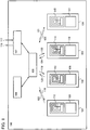
- Embodiment Mode 1 describes an example of a structure of a semiconductor device of the present invention with reference to FIGS. 1 to 3.
- FIGS. 1 to 3 are block diagrams of a semiconductor device, a CPU, and a router circuit of this embodiment mode, respectively.
- a semiconductor device 100 has first to fourth CPUs 101 to 104, a router circuit 105, a thread control circuit 106, and an external device controller 107.
- the first to fourth CPUs 101 to 104 have first to fourth CPU cores 108 to 111 and first to fourth wireless circuits 112 to 115, respectively.
- the router circuit 105 transmits first to fourth wireless transmission signals 118 to 121 to the first to fourth CPUs 101 to 104, and the first to fourth CPUs 101 to 104 transmit fifth to eighth wireless transmission signals 122 to 125 to the router circuit 105, respectively.
- the semiconductor device 100 transmits and receives a data signal or a control signal to and from an external device connected to the semiconductor device 100 with the use of an external data output line 116 and an external data input line 117.
- a CPU 200 corresponds to each of the first to fourth CPUs 101 to 104 of FIG. 1 ; a CPU core 201 corresponds to each of the first to fourth CPU cores 108 to 111 of FIG. 1 ; and a wireless circuit 202 corresponds to each of the first to fourth wireless circuits 112 to 115 of FIG. 1 .
- the CPU core 201 has a control circuit 203, an arithmetic circuit 204, a cache memory 205, and a general purpose register 206.
- the control circuit 203 controls the processing in the CPU 200.
- the arithmetic circuit 204 performs numerical operation and logical operation.
- the cache memory 205 is a storage device which stores programs processed by the CPU 200 and data necessary for the processing.
- the general purpose register 206 is used as a storage source of data which are used for numerical operation and logical operation and as a storage destination of operation results.
- the CPU core 201 can employ an architecture such as a reduced instruction set computer (RISC) or a complex instruction set computer (CISC).
- RISC reduced instruction set computer
- CISC complex instruction set computer
- the wireless circuit 202 has an antenna circuit 207, a demodulation circuit 208, a modulation circuit 209, and a power supply circuit 210.
- the antenna circuit 207 functions to transmit and receive a communication signal.
- the antenna circuit 207 may be provided with a coil in the case of employing an electromagnetic induction method, or may be provided with a dipole antenna in the case of employing an electric field method.
- the demodulation circuit 208 functions to extract reception data from a communication signal.
- the demodulation circuit 208 may be a low-pass filter (LPF).
- the modulation circuit 209 functions to superimpose transmission data on a communication signal.
- the power supply circuit 210 functions to generate a power supply voltage for the CPU 200 from a communication signal.
- the power supply circuit 210 can be formed using a rectifier circuit and a storage capacitor.
- this embodiment mode describes a so-called passive CPU which generates a power supply voltage from a wireless signal received, a so-called active CPU which supplies a power supply voltage from an incorporated battery can also be used.
- a structure in which a power supply voltage is supplied from a commercial power supply can also be used.
- the data transmission from the first to fourth CPUs 101 to 104 to the router circuit 105 is conducted using a modulation method by turning on or off a switch of the modulation circuit, i.e., a backscattering method.
- a phase modulation method or an amplitude modulation method can be used.
- a data encoding method a technique such as a quadrature phase shift keying (QPSK) method, a binary phase shift keying (BPSK) method, or an 8 phase shift keying (8PSK) method can be used.
- QPSK quadrature phase shift keying
- BPSK binary phase shift keying
- 8PSK 8 phase shift keying
- each of the QPSK method, the BPSK method, and the 8PSK method is a modulation method for converting digital values into analog signals and is a phase shift keying method for expressing information using a combination of a plurality of waves with phase shifts.
- the QPSK method four-value (2-bit) information can be transmitted or received at a time by using a total of four waves, a reference sine wave and waves with phase shifts of 90°, 180°, and 270°, and by allocating different values to each of them.
- the BPSK method two-value (1-bit) information can be transmitted or received at a time by using a reference sine wave and a wave with an inverted phase and by relating one of them to 0 and the other to 1.
- the 8PSK method eight-value (3-bit) information can be transmitted or received at a time by using a total of eight waves, a reference sine wave and waves with phase shifts of 45° each and by allocating different values to each of them.
- a router circuit 300 corresponding to the router circuit 105 of FIG. 1 has an antenna circuit 301, a demodulation circuit 302, a modulation circuit 303, a first bus controller circuit 304, a second bus controller circuit 305, and a data processing circuit 306.
- the antenna circuit 301, the demodulation circuit 302, and the modulation circuit 303 are collectively referred to as a wireless circuit 309.
- the antenna circuit 301 functions to transmit and receive a communication signal to and from the CPUs.
- the antenna circuit 301 may be provided with a coil in the case of employing an electromagnetic induction method, or may be provided with a dipole antenna in the case of employing an electric field method.
- the demodulation circuit 302 functions to extract reception data from a communication signal.
- the demodulation circuit 302 may be an LPF.
- the modulation circuit 303 functions to superimpose transmission data on a communication signal.
- the first bus controller circuit 304 is connected to the thread control circuit 106 of FIG. 1 through a first bus 307 and functions to control data transmission and reception to and from the thread control circuit 106.
- the second bus controller circuit 305 is connected to the external device controller 107 of FIG. 1 through a second bus 308 and functions to control data transmission and reception to and from the external device controller 107.
- the data processing circuit 306 functions to process and store reception data from the CPUs, transmission data to the CPUs, data input and output through the first bus 307, and data input and output through the second bus 308, and functions to manage and conduct data transmission and reception between the CPUs, between the CPUs and the thread control circuit, and between the CPUs and the external device controller.
- the router circuit 105 can function to mediate data transmission and reception between the first to fourth CPUs 101 to 104 and the thread control circuit 106 or the external device controller 107. For example, when the router circuit 105 receives, from the first CPU 101, transmission data to which the external device controller 107 is designated as a data transmission destination, the router circuit 105 transmits the data to the transmission destination, i.e., the external device controller 107.
- the router circuit 105 By employing such a method as described above by which data transmission and reception are mediated by the router circuit 105, there is an advantage that competition in data transmission and reception between the CPUs, between the CPUs and the thread controller circuit, and between the CPUs and the external device controller hardly occurs even if a plurality of CPUs are provided.
- data transmission and reception can be efficiently allocated to the CPU, the thread control circuit, or the external device controller which requires data transmission and reception.
- a wireless signal is used for data transmission from the router circuit 105 to the first to fourth CPUs 101 to 104, and a technique such as a time division multiple access (TDMA) method or a code division multiple access (CDMA) method can be employed.
- TDMA time division multiple access
- CDMA code division multiple access
- Data transmission and reception between the router circuit 105 and the thread control circuit 106 or the external device controller 107 can be conducted using a wireless signal or a wired signal.
- the TDMA method is a method in which a single frequency is shared by a plurality of transmitters in turn at short intervals.
- the CMDA method is a method by which transmission data of a plurality of transmitters are each multiplied by different codes and all transmission data are synthesized and transmitted using a single frequency.
- a receiver can extract only transmission data of a relevant transmitter by multiplying the synthesized signal with the code of the relevant transmitter.
- the thread control circuit 106 functions to allocate processing (a thread) to be executed by a CPU to the CPU. Specifically, the thread control circuit 106 functions to schedule threads with the use of information showing an operation state such as being running or idle, information showing running and idle threads, and information about the order of thread priorities, with respect to the first to fourth CPUs 101 to 104 in the semiconductor device 100. In addition, the thread control circuit 106 functions to allocate information about a CPU assigned to handle processing and data necessary for the processing to a thread to produce thread information and functions to transmit the thread information to the router circuit 105. Note that the thread information is transmitted to the relevant CPU of the first to fourth CPUs 101 to 104 through the router circuit 105 and executed appropriately.
- a thread is a unit of processing of a CPU.
- a normal CPU employs a processing method called multitasking.
- a plurality of processes are pseudo-simultaneously executed by temporally changing processes.
- changing processes may require a changing operation with heavy load such as data storing or reading of an internal register of a CPU.
- a thread is a process which is divided so that a changing process is not needed. In other words, the division of processing into threads enables efficient multitasking.
- the external device controller 107 functions to transmit and receive a data signal or a control signal between the semiconductor device 100 and an external device connected to the semiconductor device 100, with the use of the external data output line 116 and the external data input line 117.
- DRAM dynamic random access memory
- the external device controller 107 functions as a DRAM controller.
- the semiconductor device 100 is connected to an external peripheral device having a PCI bus
- the external device controller 107 functions as a PCI bus controller.
- the external device controller 107 functions as a USB controller.
- the external device controller 107 functions to transmit and receive data to and from the router circuit 105.
- the first CPU 101 executes an instruction to generate a new thread
- the first CPU 101 transmits an instruction requiring generation of a thread to the thread control circuit 106 through the router circuit 105.
- the thread control circuit 106 determines a CPU, to which the thread is to be allocated, from idle CPUs or CPUs executing threads with low priority, and transmits thread information including an address of an instruction to be executed to the CPU through the router circuit.
- the thread control circuit 106 has a function to allocate a thread to a relevant CPU, i.e., a scheduling function.
- allocation of a thread to a relevant CPU is carried out by software with the use of a thread scheduling function of an operating system (OS) corresponding to a multiprocessor.
- OS operating system
- the scheduling function itself is achieved by a thread; therefore, a CPU is used.
- operation performance of the semiconductor device as a whole is lowered.
- the semiconductor device of the present invention can realize thread scheduling without lowering the arithmetic processing performance of a CPU by provision of a thread control circuit having a thread scheduling function.
- the semiconductor device of the present invention can realize thread scheduling without lowering the operation performance of a CPU.
- Embodiment Mode 2 describes the structure of the wireless circuit of the CPU in the above embodiment mode with reference to FIG. 4.
- FIG. 4 shows a case where the wireless circuit has the antenna circuit 207, the demodulation circuit 208, the modulation circuit 209, and the power supply circuit 210.
- the modulation circuit 209 has a transistor 406 and can superimpose transmission data on a communication signal by changing the potential of a modulation signal line 402.
- the demodulation circuit 208 has a first coupling capacitor 407, a first diode 408, a second diode 409, an LPF resistor 410, and an LPF capacitor 411.
- a first AC voltage obtained from a communication signal by the antenna circuit 207 is supplied through a wiring 401 and converted into a second AC voltage by the first coupling capacitor 407, and the second AC voltage is supplied to a wiring 412.
- the second AC voltage is converted into a DC voltage by a rectifier circuit which has the first diode 408 and the second diode 409, and the DC voltage is supplied to a wiring 413.
- the DC voltage is converted into a demodulated signal by an LPF which has the LPF resistor 410 and the LPF capacitor 411, and the demodulated signal is supplied to a demodulation signal line 403.
- the power supply circuit 210 has a second coupling capacitor 414, a third diode 415, a fourth diode 416, and a storage capacitor 417.
- the first AC voltage obtained from a communication signal by the antenna circuit 207 is supplied through the wiring 401 and converted into a third AC voltage by the second coupling capacitor 414, and the third AC voltage is supplied to a wiring 418.
- the third AC voltage is converted into a power supply signal by a rectifier circuit which has the third diode 415 and the fourth diode 416, and the power supply signal is supplied to a power supply wiring 404.
- the power supply signal is smoothed by the storage capacitor 417. Note that a ground signal is supplied through a ground wiring 405.
- a wireless circuit which enables wireless data transmission and reception in a CPU and by performing data transmission and reception between CPUs or the like with the use of a backscattering method of a wireless signal through a router, a semiconductor device which consumes less power and has high arithmetic performance can be provided at low cost.
- Embodiment Mode 3 describes a structure of a wireless circuit of a CPU, which is different from that of Embodiment Mode 2, with reference to FIG. 5 .
- the antenna circuit 207 has a first antenna 534 and a second antenna 535.
- the first antenna 534 is used for data transmission and reception with a first communication signal and for generation of a first power supply voltage from the first communication signal.
- the second antenna 535 is used for generation of a second power supply voltage from a second communication signal.
- the modulation circuit 209 has a transistor 506 and can superimpose transmission data on the first communication signal by changing the potential of a modulation signal line 502.
- the demodulation circuit 208 has a first coupling capacitor 507, a first diode 508, a second diode 509, an LPF resistor 510, and an LPF capacitor 511.
- a first AC voltage obtained from the first communication signal by the first antenna 534 is supplied through a wiring 501 and converted into a second AC voltage by the first coupling capacitor 507, and the second AC voltage is supplied to a wiring 512.
- the second AC voltage is converted into a first DC voltage by a rectifier circuit which has the first diode 508 and the second diode 509, and the first DC voltage is supplied to a wiring 513.
- the first DC voltage is converted into a demodulated signal by an LPF which has the LPF resistor 510 and the LPF capacitor 511, and the modulated signal is supplied to a demodulation signal line 503.
- the power supply circuit 210 has a first power supply circuit 536 and a second power supply circuit 537.
- the first power supply circuit 536 has a second coupling capacitor 514, a third diode 515, a fourth diode 516, and a first storage capacitor 517.
- the first AC voltage obtained from the first communication signal by the first antenna 534 is supplied through the wiring 501 and converted into a third AC voltage by the second coupling capacitor 514, and the third AC voltage is supplied to a wiring 518.
- the third AC voltage is converted into a first power supply signal by a rectifier circuit which has the third diode 515 and the fourth diode 516, and the first power supply signal is supplied to a first power supply wiring 539.
- the first power supply signal is smoothed by the first storage capacitor 517.
- the second power supply circuit 537 has a third coupling capacitor 519, a fourth coupling capacitor 520, fifth to eighth diodes 521 to 524, a second storage capacitor 525, and a third storage capacitor 526.
- a fourth AC voltage obtained from the second communication signal by the second antenna 535 is supplied through a wiring 538 and converted into a fifth AC voltage by the third coupling capacitor 519, and the fifth AC voltage is supplied to a wiring 527.
- the fifth AC voltage is converted into a second DC voltage by a rectifier circuit which has the fifth diode 521 and the sixth diode 522, and the second DC voltage is supplied to a wiring 528.
- the second DC voltage is smoothed by the second storage capacitor 525.
- the fifth AC voltage is converted into a sixth AC voltage by the fourth coupling capacitor 520, and the sixth AC voltage is supplied to a wiring 529.
- the sixth AC voltage is converted into a third DC voltage by a rectifier circuit which has the seventh diode 523 and the eighth diode 524, and the third DC voltage is supplied to a second power supply wiring 530 as a second power supply signal.
- the second power signal is smoothed by the third storage capacitor 526. Note that the second power supply signal is increased to a high potential when added to a potential accumulated in the second storage capacitor 525.
- a power supply signal with a higher potential of the first power supply signal and the second power supply signal is supplied to a power supply wiring 504 as a power supply voltage.
- the power supply voltage is smoothed by a fourth storage capacitor 533.
- a ground signal is supplied through a ground wiring 505.
- the fourth storage capacitor 533 can be a capacitor such as an electric double layer capacitor.
- the fourth storage capacitor 533 may be a secondary battery such as a lithium battery, preferably a lithium polymer battery using a gel electrolyte, or a lithium-ion battery.
- the second power supply circuit 537 is a step-up circuit.
- it is possible to supply a power supply voltage sufficient for operating a CPU even when the second communication signal is weak.
- continuous supply of weak second communication signal enables a CPU to continue its operation even if the first communication signal is supplied only when the CPU conducts wireless communication and the first communication signal is stopped from being supplied when the CPU does not conduct wireless communication. Accordingly, wireless communication with a CPU can be achieved with less power consumption.
- a semiconductor device which consumes less power and has high arithmetic performance can be provided at low cost.
- Embodiment Mode 4 describes an example of a method for manufacturing the semiconductor device described in the above embodiment modes with reference to drawings.
- This embodiment mode describes a structure in which an antenna circuit and a power supply circuit in a CPU of the semiconductor device are formed using thin film transistors over the same substrate. It is to be noted that when an antenna circuit and a power supply circuit are formed at a time over the same substrate, reduction in size of the semiconductor device can be achieved, which is advantageous.
- this embodiment mode describes an example in which a thin-film secondary battery is used as a storage capacitor in the power supply circuit. Needless to say, instead of the secondary battery, a capacitor such as an electric double layer capacitor may be used.
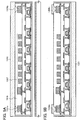
- a peeling layer 1303 is formed over one surface of a substrate 1301 with an insulating film 1302 interposed therebetween, and then an insulating film 1304 functioning as a base film and a semiconductor film (e.g., a film containing amorphous silicon) 1305 are stacked thereover (see FIG. 6A ).
- a semiconductor film e.g., a film containing amorphous silicon
- the insulating film 1302, the peeling layer 1303, the insulating film 1304, and the semiconductor film 1305 can be formed consecutively.
- the substrate 1301 is selected from a glass substrate, a quartz substrate, a metal substrate (e.g., a ceramic substrate or a stainless steel substrate), a semiconductor substrate such as a Si substrate, and the like.
- a plastic substrate made of polyethylene terephthalate (PET), polyethylene naphthalate (PEN), polyether sulfone (PES), acrylic, or the like can be used.
- PET polyethylene terephthalate
- PEN polyethylene naphthalate
- PES polyether sulfone
- acrylic acrylic
- the insulating films 1302 and 1304 are formed using insulating materials such as silicon oxide, silicon nitride, silicon oxynitride (SiO x N y , where x > y > 0), or silicon nitride oxide (SiN x O y , where x > y > 0) by a CVD method, a sputtering method, or the like.
- insulating materials such as silicon oxide, silicon nitride, silicon oxynitride (SiO x N y , where x > y > 0), or silicon nitride oxide (SiN x O y , where x > y > 0) by a CVD method, a sputtering method, or the like.
- a silicon nitride oxide film may be formed as a first insulating film and a silicon oxynitride film may be formed as a second insulating film.
- a silicon nitride film may be formed as a first insulating film and a silicon oxide film may be formed as a second insulating film.
- the insulating film 1302 functions as a blocking layer which prevents an impurity element contained in the substrate 1301 from getting mixed into the peeling layer 1303 or elements formed thereover.
- the insulating film 1304 functions as a blocking layer which prevents an impurity element contained in the substrate 1301 or the peeling layer 1303 from getting mixed into elements formed over the insulating film 1304.
- the insulating films 1302 and 1304 which function as the blocking layers can prevent adverse effects on the elements formed over the peeling layer 1303 or the insulating film 1304, which would otherwise be caused by an alkali metal such as Na or an alkaline earth metal contained in the substrate 1301 or by the impurity element contained in the peeling layer 1303. It is to be noted that when quartz is used for the substrate 1301, for example, the insulating film 1302 may be omitted.
- the peeling layer 1303 may be formed using a metal film, a stacked structure of a metal film and a metal oxide film, or the like.
- a metal film either a single layer or stacked layers is/are formed using an element selected from tungsten (W), molybdenum (Mo), titanium (Ti), tantalum (Ta), niobium (Nb), nickel (Ni), cobalt (Co), zirconium (Zr), zinc (Zn), ruthenium (Ru), rhodium (Rh), palladium (Pd), osmium (Os), and iridium (Ir), or an alloy material or a compound material containing such an element as its main component.
- Such materials can be formed by a sputtering method, various CVD methods such as a plasma CVD method, or the like.
- a stacked structure of a metal film and a metal oxide film can be obtained by the steps of forming the above-described metal film, applying plasma treatment thereto under an oxygen atmosphere or an N 2 O atmosphere or applying heat treatment thereto under an oxygen atmosphere or an N 2 O atmosphere, and thereby forming oxide or oxynitride of the metal film on the surface of the metal film.
- a metal oxide film of tungsten oxide can be formed on the surface of the tungsten film by application of plasma treatment to the tungsten film.
- tungsten oxide there is no particular limitation on the amount of oxygen, and thus, which of the above oxides is to be formed may be determined based on the etching rate or the like.
- a metal film e.g., tungsten
- an insulating film formed of silicon oxide (SiO 2 ) or the like may be formed over the metal film by a sputtering method, and also metal oxide (e.g., tungsten oxide on tungsten) may be formed on the metal film.
- high-density-plasma treatment as described above may be applied as the plasma treatment, for example.
- metal nitride or metal oxynitride may also be formed. In that case, plasma treatment or heat treatment may be applied to the metal film under a nitrogen atmosphere or an atmosphere containing nitrogen and oxygen.
- the amorphous semiconductor film 1305 is formed with a thickness of 25 to 200 nm (preferably, 30 to 150 nm) by a sputtering method, an LPCVD method, a plasma CVD method, or the like.
- the amorphous semiconductor film 1305 is crystallized by laser irradiation.
- the crystallization of the amorphous semiconductor film 1305 may be performed by a method combining the laser crystallization with a thermal crystallization method using RTA or an annealing furnace or with a thermal crystallization method using a metal element that promotes the crystallization.
- the crystallized semiconductor film is etched into a desired shape, whereby crystalline semiconductor films 1305a to 1305f are formed.
- a gate insulating film 1306 is formed so as to cover the semiconductor films 1305a to 1305f (see FIG. 6B ).
- the gate insulating film 1306 is formed using an insulating material such as silicon oxide, silicon nitride, silicon oxynitride (SiO x N y where x > y > 0), or silicon nitride oxide (SiN x O y , where x > y> 0) by a CVD method, a sputtering method, or the like.
- an insulating material such as silicon oxide, silicon nitride, silicon oxynitride (SiO x N y where x > y > 0), or silicon nitride oxide (SiN x O y , where x > y> 0) by a CVD method, a sputtering method, or the like.
- a silicon oxynitride film as a first insulating film and form a silicon nitride oxide film as a second insulating film.
- an amorphous semiconductor film with a thickness of 50 to 60 nm is formed by a plasma CVD method. Then, a solution containing nickel which is a metal element that promotes crystallization is retained on the amorphous semiconductor film, which is followed by dehydrogenation treatment (500°C for one hour) and thermal crystallization treatment (550°C for four hours). Thus, a crystalline semiconductor film is formed. Then, the crystalline semiconductor film is subjected to laser irradiation and then a photolithography process to form the crystalline semiconductor films 1305a to 1305f. It is to be noted that crystallization of the amorphous semiconductor film may be performed only by laser irradiation, not by thermal crystallization which uses a metal element that promotes crystallization.
- a laser oscillator used for crystallization either a continuous wave laser oscillator (a CW laser oscillator) or a pulsed laser oscillator can be used.
- a laser that can be used here there are a gas laser such as an Ar laser, a Kr laser, or an excimer laser; a laser whose medium is single-crystalline YAG, YVO 4 , forsterite (Mg 2 SiO 4 ), YAlO 3 , or GdVO 4 or polycrystalline (ceramic) YAG, Y 2 O 3 , YVO 4 , YAlO 3 , or GdVO 4 doped with one or more of Nd, Yb, Cr, Ti, Ho, Er, Tm, and Ta as a dopant; a glass laser; a ruby laser; an alexandrite laser; a Ti:sapphire laser; a copper vapor laser; and a gold vapor laser.
- a gas laser such as an Ar laser, a Kr laser, or
- crystals with a large grain size can be obtained.
- the second harmonic (532 nm) or the third harmonic (355 nm) of an Nd:YVO 4 laser (the fundamental wave of 1064 nm) can be used.
- a laser power density of approximately 0.01 to 100 MW/cm 2 preferably, 0.1 to 10 MW/cm 2
- irradiation is performed with a scanning rate of approximately 10 to 2000 cm/sec.
- the laser whose medium is single crystalline YAG, YVO 4 , forsterite (Mg 2 SiO 4 ), YAlO 3 , or GdVO 4 or polycrystalline (ceramic) YAG, Y 2 O 3 , YVO 4 , YAlO 3 , or GdVO 4 doped with one or more of Nd, Yb, Cr, Ti, Ho, Er, Tm, and Ta as a dopant; an Ar ion laser, or a Ti:sapphire laser can be used as a CW laser, whereas it can also be used as a pulsed laser with a repetition rate of 10 MHz or more by a Q-switch operation, mode locking, or the like.
- a semiconductor film is irradiated with the next pulse during the period in which the semiconductor film has been melted by the laser beam and is solidified. Therefore, unlike the case of using a pulsed laser with a low repetition rate, a solid-liquid interface in the semiconductor film can be continuously moved. Thus, crystal grains which have grown continuously in the scanning direction can be obtained.
- the gate insulating film 1306 may be formed by oxidization or nitridation of the surfaces of the semiconductor films 1305a to 1305f by the above-described high-density plasma treatment.
- plasma treatment with a mixed gas of a rare gas such as He, Ar, Kr, or Xe, and oxygen, nitrogen oxide (NO 2 ), ammonia, nitrogen, or hydrogen is conducted.
- plasma is excited by the introduction of microwaves, plasma with a low electron temperature and high density can be generated.
- oxygen radicals which may include OH radicals
- nitrogen radicals which are generated by the high-density plasma, a surface of a semiconductor film can be oxidized or nitrided.
- an insulating film with a uniform thickness and low interface state density can be formed without excessive oxidation reaction at the crystal grain boundaries.
- the gate insulating film only an insulating film formed by high-density plasma treatment may be used, or a stacked layer may be employed, which is obtained by deposition of an insulating film such as silicon oxide, silicon oxynitride, or silicon nitride on the insulating film, by a CVD method using plasma or thermal reaction. In either case, a transistor which includes such an insulating film formed by high-density plasma treatment in a part or the whole of its gate insulating film can have reduced characteristic variations.
- the semiconductor films 1305a to 1305f which are obtained by irradiation of a semiconductor film with a continuous wave laser beam or a laser beam oscillated with a repetition rate of 10 MHz or more and scanning the semiconductor film with the laser beam in one direction to crystallize the semiconductor film, have a characteristic in that their crystals grow in the beam scanning direction.
- Transistors are each arranged so that its channel length direction (direction in which carriers move when a channel formation region is formed) is aligned with the scanning direction, and the above-described gate insulating film is combined with the semiconductor film, whereby thin film transistors (TFTs) with high electron field effect mobility and reduced variations in characteristics can be obtained.
- first conductive film and a second conductive film are stacked over the gate insulating film 1306.
- first conductive film is formed to a thickness of 20 to 100 nm by a CVD method, a sputtering method, or the like.
- the second conductive film is formed to a thickness of 100 to 400 nm.
- the first conductive film and the second conductive film are formed of an element selected from tantalum (Ta), tungsten (W), titanium (Ti), molybdenum (Mo), aluminum (Al), copper (Cu), chromium (Cr), niobium (Nb), and the like, or an alloy material or a compound material containing such an element as its main component.
- a semiconductor material typified by polycrystalline silicon doped with an impurity element such as phosphorus can also be used.
- a tantalum nitride film and a tungsten film As combination examples of the first conductive film and the second conductive film, a tantalum nitride film and a tungsten film; a tungsten nitride film and a tungsten film; a molybdenum nitride film and a molybdenum film; and the like can be given.
- Tungsten and tantalum nitride have high heat resistance. Therefore, after forming the first conductive film and the second conductive film, heat treatment for the purpose of thermal activation can be applied thereto.
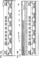
- gate electrodes 1307 are formed above the semiconductor films 1305a to 1305f.
- a stacked structure of a first conductive film 1307a and a second conductive film 1307b is shown as an example of the gate electrode 1307.
- the semiconductor films 1305a to 1305f are doped with an n-type impurity element at low concentration, using the gate electrodes 1307 as masks by an ion doping method or an ion implantation method. Then, a resist mask is selectively formed by photolithography, and the semiconductor films 1305c and 1305e are doped with a p-type impurity element at high concentration.
- n-type impurity element phosphorus (P), arsenic (As), or the like can be used.
- As a p-type impurity element boron (B), aluminum (Al), gallium (Ga), or the like can be used.
- phosphorus (P) is used as an n-type impurity element and is selectively introduced into the semiconductor films 1305a to 1305f so as to be contained at concentrations of 1 ⁇ 10 15 to 1 ⁇ 10 19 /cm 3 .
- n-type impurity regions 1308 are formed.
- boron (B) is used as a p-type impurity element, and is selectively introduced into the semiconductor films 1305c and 1305e so as to be contained at concentrations of 1 ⁇ 10 19 to 1 ⁇ 10 20 /cm 3 .
- p-type impurity regions 1309 are formed (see FIG. 6C ).
- an insulating film is formed so as to cover the gate insulating film 1306 and the gate electrodes 1307.
- the insulating film is formed using either a single layer or a stacked layer of a film containing an inorganic material such as silicon, silicon oxide, or silicon nitride, or a film containing an organic material such as an organic resin by a plasma CVD method, a sputtering method, or the like.
- the insulating film is selectively etched by anisotropic etching mainly in the perpendicular direction, so that insulating films 1310 (also referred to as sidewalls) which are in contact with the side surfaces of the gate electrodes 1307 are formed.
- the insulating films 1310 are used as masks in doping for forming LDD (Lightly Doped Drain) regions.
- the semiconductor films 1305a, 1305b, 1305d, and 1305f are doped with an n-type impurity element at high concentration, using resist masks formed by photolithography, the gate electrodes 1307, and the insulating films 1310 as masks.
- n-type impurity regions 1311 are formed.
- phosphorus (P) is used as an n-type impurity element, and is selectively introduced into the semiconductor films 1305a, 1305b, 1305d, and 1305f so as to be contained at concentrations of 1 ⁇ 10 19 to 1 ⁇ 10 20 /cm 3 .
- the n-type impurity regions 1311 with higher concentration of impurity than that of the impurity regions 1308 are formed.
- n-channel thin film transistors 1300a, 1300b, 1300d, and 1300f, and p-channel thin film transistors 1300c and 1300e are formed (see FIG. 6D ).
- a channel formation region is formed in a region of the semiconductor film 1305a which overlaps with the gate electrode 1307; the impurity regions 1311 serving as source and drain regions are formed in regions of the semiconductor film 1305a which do not overlap with the gate electrode 1307 and the insulating film 1310; and low concentration impurity regions (LDD regions) are formed in regions of the semiconductor film 1305a which overlap with the insulating film 1310, between the channel formation region and the impurity regions 1311.
- LDD regions low concentration impurity regions
- channel formation regions, low concentration impurity regions, and the impurity regions 1311 are formed in the n-channel thin film transistors 1300b, 1300d, and 1300f.
- a channel formation region is formed in a region of the semiconductor film 1305c which overlaps with the gate electrode 1307, and the impurity regions 1309 serving as source and drain regions are formed in regions of the semiconductor film 1305c which do not overlap with the gate electrode 1307.
- a channel formation region and the impurity regions 1309 are formed in the p-channel thin film transistor 1300e.
- LDD regions are not formed in the p-channel thin film transistors 1300c and 1300e, LDD regions may be provided in the p-channel thin film transistors or a structure without LDD regions may be applied to the n-channel thin film transistors.
- an insulating film with a single layer structure or a stacked layer structure is formed so as to cover the semiconductor films 1305a to 1305f, the gate electrodes 1307, and the like.
- conductive films 1313 electrically connected to the impurity regions 1309 and 1311 which serve as the source and drain regions of the thin film transistors 1300a to 1300f are formed over the insulating film (see FIG. 7A ).
- the insulating film is formed with a single layer or a stacked layer, using an inorganic material such as silicon oxide or silicon nitride, an organic material such as polyimide, polyamide, benzocyclobutene, acrylic, or epoxy, a siloxane material, or the like by a CVD method, a sputtering method, an SOG method, a droplet discharging method, a screen printing method, or the like.
- the insulating film is formed to have a two-layer structure, and a silicon nitride oxide film is formed as a first insulating film 1312a and a silicon oxynitride film is formed as a second insulating film 1312b.
- the conductive films 1313 can form the source and drain electrodes of the thin film transistors 1300a to 1300f.
- heat treatment is preferably conducted for recovery of the crystallinity of the semiconductor films, activation of the impurity element which has been added into the semiconductor films, or hydrogenation of the semiconductor films.
- heat treatment thermal annealing, laser annealing, RTA, or the like may be applied.
- the conductive films 1313 are formed with a single layer or a stacked layer of an element selected from aluminum (Al), tungsten (W), titanium (Ti), tantalum (Ta), molybdenum (Mo), nickel (Ni), platinum (Pt), copper (Cu), gold (Au), silver (Ag), manganese (Mn), neodymium (Nd), carbon (C), and silicon (Si), or an alloy material or a compound material containing the element as its main component by a CVD method, a sputtering method, or the like.
- an element selected from aluminum (Al), tungsten (W), titanium (Ti), tantalum (Ta), molybdenum (Mo), nickel (Ni), platinum (Pt), copper (Cu), gold (Au), silver (Ag), manganese (Mn), neodymium (Nd), carbon (C), and silicon (Si), or an alloy material or a compound material containing the element as its main component by a CV
- An alloy material containing aluminum as its main component corresponds to, for example, a material which contains aluminum as its main component and also contains nickel, or a material which contains aluminum as its main component and also contains nickel and one or both of carbon and silicon.
- the conductive films 1313 are preferably formed to have a stacked structure of a barrier film, an aluminum silicon (Al-Si) film, and a barrier film or a stacked structure of a barrier film, an aluminum silicon (Al-Si) film, a titanium nitride film, and a barrier film.
- the "barrier film” corresponds to a thin film formed of titanium, titanium nitride, molybdenum, or molybdenum nitride.
- Aluminum and aluminum silicon are suitable materials for forming the conductive films 1313 because they have low resistance value and are inexpensive.
- barrier layers are provided as the top layer and the bottom layer, generation of hillocks of aluminum or aluminum silicon can be prevented.
- a barrier film is formed of titanium which is an element having a high reducing property, even if a thin natural oxide film is formed on the crystalline semiconductor film, the natural oxide film can be reduced, and a favorable contact between the conductive film 1313 and the crystalline semiconductor film can be obtained.
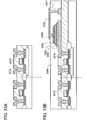
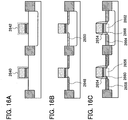
- an insulating film 1314 is formed so as to cover the conductive films 1313, and conductive films 1315a and 1315b electrically connected to the conductive films 1313 which form the source electrodes or the drain electrodes of the thin film transistors 1300a and 1300f are formed over the insulating film 1314.
- a conductive film 1316 electrically connected to the conductive film 1313 which forms the source electrode or drain electrode of the thin film transistor 1300b is formed.
- the conductive films 1315a and 1315b and the conductive film 1316 may be formed using the same material at the same time.
- the conductive films 1315a and 1315b and the conductive film 1316 can be formed using any of the above-described materials for the conductive film 1313.
- a conductive film 1317 functioning as an antenna is formed so as to be electrically connected to the conductive film 1316 (see FIG. 7B ).
- the insulating film 1314 can be formed with a single layer or a stacked layer of an insulating film containing oxygen and/or nitrogen such as silicon oxide (SiO x ), silicon nitride (SiN x ), silicon oxynitride (SiO x N y where x > y > 0), or silicon nitride oxide (SiN x O y where x > y > 0); a film containing carbon such as DLC (Diamond-Like Carbon); an organic material such as epoxy, polyimide, polyamide, polyvinyl phenol, benzocyclobutene, or acrylic; or a siloxane material such as a siloxane resin by a CVD method, a sputtering method, or the like.
- silicon oxide SiO x
- SiN x silicon nitride
- SiO x N y silicon oxynitride
- SiN x O y silicon nitride oxide
- a siloxane material corresponds to a material having a bond of Si-O-Si.
- Siloxane has a skeleton structure with the bond of silicon (Si) and oxygen (O).
- an organic group containing at least hydrogen e.g., an alkyl group or aromatic hydrocarbon
- a fluoro group may be used as the substituent.
- both a fluoro group and an organic group containing at least hydrogen may be used as the substituent.
- the conductive film 1317 is formed of a conductive material by a CVD method, a sputtering method, a printing method such as screen printing or gravure printing, a droplet discharging method, a dispenser method, a plating method, or the like.
- the conductive film 1317 is formed with a single layer or a stacked layer of an element selected from aluminum (Al), titanium (Ti), silver (Ag), copper (Cu), gold (Au), platinum (Pt), nickel (Ni), palladium (Pd), tantalum (Ta), and molybdenum (Mo), or an alloy material or a compound material containing such an element as its main component.
- the conductive film 1317 functioning as an antenna when the conductive film 1317 functioning as an antenna is formed by a screen printing method, the conductive film 1317 can be provided by selective printing of a conductive paste in which conductive particles with a grain diameter of several nanometers to several tens of micrometers are dissolved or dispersed in an organic resin.
- the conductive particles can be at least one or more of metal particles selected from silver (Ag), gold (Au), copper (Cu), nickel (Ni), platinum (Pt), palladium (Pd), tantalum (Ta), molybdenum (Mo), titanium (Ti), and the like; fine particles of silver halide; and dispersive nanoparticles thereof.
- the organic resin included in the conductive paste can be one or more of organic resins which function as a binder, a solvent, a dispersing agent, and a coating material of the metal particles.
- organic resins such as an epoxy resin and a silicone resin can be given as examples.
- a conductive paste is extruded and then baked to form the conductive film.
- fine particles e.g., a grain diameter of 1 to 100 nm
- the conductive paste is baked and hardened at temperatures of 150 to 300°C, so that the conductive film can be obtained.
- solder or lead-free solder it is also possible to use fine particles containing solder or lead-free solder as its main component. In that case, fine particles with a grain diameter of 20 ⁇ m or less are preferably used. Solder and lead-free solder have the advantage of low cost.
- the conductive films 1315a and 1315b can function as wirings which are electrically connected to a secondary battery included in the semiconductor device of the present invention in a later step.
- other conductive films may be separately formed so as to be electrically connected to the conductive films 1315a and 1315b, so that the conductive films can be utilized as the wirings for connecting the conductive films 1315a and 1315b to the secondary battery.
- an insulating film 1318 so as to cover the conductive film 1317
- a layer including the thin film transistors 1300a to 1300f, the conductive film 1317, and the like (hereinafter referred to as an "element formation layer 1319") is peeled off the substrate 1301.
- the element formation layer 1319 can be peeled off the substrate 1301 with a physical force.
- the peeling layer 1303 may be selectively removed by introduction of an etchant into the opening portions before peeling the element formation layer 1319 off the substrate 1301.
- a gas or a liquid containing halogen fluoride or an interhalogen compound is used as the etchant.
- ClF 3 chlorine trifluoride
- the element formation layer 1319 is peeled off the substrate 1301.
- the whole peeling layer 1303 does not necessarily be removed but part thereof may be left. Accordingly, the consumption of the etchant can be suppressed and process time needed for removing the peeling layer can be shortened.
- the element formation layer 1319 can be held above the substrate 1301.
- cost reduction can be achieved.
- the insulating film 1318 can be formed with a single layer or a stacked layer of an insulating film containing oxygen and/or nitrogen such as silicon oxide (SiO x ), silicon nitride (SiN x ), silicon oxynitride (SiO x N y where x > y > 0), or silicon nitride oxide (SiN x O y where x > y > 0); a film containing carbon such as DLC (Diamond-Like Carbon); an organic material such as epoxy, polyimide, polyamide, polyvinyl phenol, benzocyclobutene, or acrylic; or a siloxane material such as a siloxane resin by a CVD method, a sputtering method, or the like.
- silicon oxide SiO x
- SiN x silicon nitride
- SiO x N y silicon oxynitride
- SiN x O y silicon nitride oxide
- a first sheet material 1320 is attached to one surface of the element formation layer 1319 (the surface where the insulating film 1318 is exposed), and then the element formation layer 1319 is peeled off the substrate 1301 (see FIG. 8A ).
- a second sheet material 1321 is provided for the other surface of the element formation layer 1319 (the surface exposed by peeling), followed by one or both of heat treatment and pressurization treatment for attachment of the second sheet material 1321 (see FIG. 8B ).
- the first sheet material 1320 and the second sheet material 1321 functions as substrates, and a plastic film such as a hot-melt film can be used.
- a substrate having an insulating surface, such as a glass substrate can be used.
- an antistatic film a film on which antistatic treatment for preventing static electricity or the like has been applied
- an antistatic film a film in which an antistatic material is dispersed in a resin, a film to which an antistatic material is attached, and the like
- the film provided with an antistatic material can be a film with an antistatic material provided on one of its surfaces, or a film with an antistatic material provided on each of its surfaces.
- the film with an antistatic material provided on one of its surfaces may be attached to the layer so that the antistatic material is placed on the inner side of the film or the outer side of the film.
- the antistatic material may be provided over the entire surface of the film, or over a part of the film.
- a metal, indium tin oxide (ITO), or a surfactant such as an amphoteric surfactant, a cationic surfactant, or a nonionic surfactant can be used.
- a resin material which contains a cross-linked copolymer having a carboxyl group and a quaternary ammonium base on its side chain, or the like can be used. Such a material is attached, mixed, or applied to a film, so that an antistatic film can be formed. The element formation layer is sealed using the antistatic film, so that the semiconductor elements can be protected from adverse effects such as external static electricity when dealt with as a commercial product.
- a thin-film secondary battery is connected to the conductive films 1315a and 1315b, so that the storage capacitor of the power supply circuit is formed.
- the connection with the secondary battery may be conducted before the element formation layer 1319 is peeled off the substrate 1301 (at the stage shown in FIG 7B or FIG 7C ), after the element formation layer 1319 is peeled off the substrate 1301 (at the stage shown in FIG. 8A ), or after the element formation layer 1319 is sealed with the first sheet material 1320 and the second sheet material 1321 (at the stage shown in FIG. 8B ).
- An example where the element formation layer 1319 and the secondary battery are formed to be connected is explained below with reference to FIGS. 9A and 9B and FIGS. 10A and 10B .
- conductive films 1331a and 1331b which are electrically connected to the conductive films 1315a and 1315b, respectively are formed at the same time as the conductive film 1317 which functions as an antenna. Then, the insulating film 1318 is formed so as to cover the conductive films 1317, 1331a, and 1331b, followed by formation of opening portions so that the surfaces of the conductive films 1331a and 1331b are exposed.
- the opening portions are formed in the element formation layer 1319 by laser irradiation, and then the first sheet material 1320 is attached to one surface of the element formation layer 1319 (the surface where the insulating film 1318 is exposed), so that the element formation layer 1319 is peeled off the substrate 1301 (see FIG. 9A ).
- the second sheet material 1321 is attached to the other surface of the element formation layer 1319 (the surface exposed by peeling), and the element formation layer 1319 is peeled off the first sheet material 1320. Therefore, a material with low viscosity is used as the first sheet material 1320. Then, conductive films 1334a and 1334b which are electrically connected to the conductive films 1331a and 1331b respectively through the opening portions are selectively formed (see FIG. 9B ).
- the conductive films 1334a and 1334b are formed of a conductive material by a CVD method, a sputtering method, a printing method such as screen printing or gravure printing, a droplet discharging method, a dispenser method, a plating method, or the like.
- the conductive films 1334a and 1334b are formed with a single layer or a stacked layer of an element selected from aluminum (Al), titanium (Ti), silver (Ag), copper (Cu), gold (Au), platinum (Pt), nickel (Ni), palladium (Pd), tantalum (Ta), and molybdenum (Mo), or an alloy material or a compound material containing the element as its main component.
- the element formation layer 1319 may be peeled off the substrate 1301 after the formation of the conductive films 1334a and 1334b.
- the element formation layer 1319 is cut into elements (see FIG. 10A ).
- a laser irradiation apparatus, a dicing apparatus, a scribing apparatus, or the like can be used for the cutting.
- the plurality of elements formed over one substrate are separated from one another by laser irradiation.
- a thin-film secondary battery is used as the storage capacitor of the power supply circuit, in which a current-collecting thin film, a negative electrode active material layer, a solid electrolyte layer, a positive electrode active material layer, and a current-collecting thin film are sequentially stacked.
- Conductive films 1336a and 1336b are formed of a conductive material by a CVD method, a sputtering method, a printing method such as screen printing or gravure printing, a droplet discharging method, a dispenser method, a plating method, or the like.
- the conductive films 1336a and 1336b are formed with a single layer or a stacked layer of an element selected from aluminum (Al), titanium (Ti), silver (Ag), copper (Cu), gold (Au), platinum (Pt), nickel (Ni), palladium (Pd), tantalum (Ta), and molybdenum (Mo), or an alloy material or a compound material containing such an element as its main component.
- the conductive material should have high adhesion to a negative electrode active material layer and also low resistance.
- aluminum, copper, nickel, vanadium, or the like is preferably used.
- a negative electrode active material layer 1381 is formed over the conductive film 1336a.
- vanadium oxide (V 2 O 5 ) or the like is used.
- a solid electrolyte layer 1382 is formed over the negative electrode active material layer 1381.
- lithium phosphate (Li 3 PO 4 ) or the like is used.
- a positive electrode active material layer 1383 is formed over the solid electrolyte layer 1382.
- lithium manganate (LiMn 2 O 4 ) or the like is used.
- Lithium cobaltate (LiCoO 2 ) or lithium nickel oxide (LiNiO 2 ) may also be used.
- a current-collecting thin film 1384 to serve as an electrode is formed over the positive electrode active material layer 1383.
- the current-collecting thin film 1384 should have high adhesion to the positive electrode active material layer 1383 and also low resistance.
- aluminum, copper, nickel, vanadium, or the like can be used.
- Each of the above thin layers of the negative electrode active material layer 1381, the solid electrolyte layer 1382, the positive electrode active material layer 1383, and the current-collecting thin film 1384 may be formed by a sputtering technique or an evaporation technique.
- the thickness of each layer is preferably 0.1 to 3 ⁇ m.
- an interlayer film 1385 is formed by application of a resin.
- the interlayer film 1385 is etched to form a contact hole.
- the interlayer film 1385 is not limited to a resin, and other films such as an oxide film formed by CVD method or the like may be used as well; however, a resin is preferably used in terms of flatness.
- the contact hole may be formed without using etching, but using a photosensitive resin.
- a wiring layer 1386 is formed over the interlayer film 1385 and connected to the conductive film 1336b. Thus, an electrical connection of the thin-film secondary battery is secured.
- the conductive films 1334a and 1334b which are provided in the element formation layer 1319 are connected to the conductive films 1336a and 1336b respectively in advance, which serve as the connection terminals of the thin-film secondary battery 1389.
- an electrical connection between the conductive films 1334a and 1336a or an electrical connection between the conductive films 1334b and 1336b is performed by pressure bonding with an adhesive material such as an anisotropic conductive film (ACF) or an anisotropic conductive paste (ACP) interposed therebetween.
- ACF anisotropic conductive film
- ACP anisotropic conductive paste
- the connection is performed using conductive particles 1338 included in an adhesive resin 1337.
- a conductive adhesive such as a silver paste, a copper paste, or a carbon paste; solder joint; or the like can be used.
- a multi-gate structure having two or more gate electrodes may be employed.
- a structure in which channel regions are connected in series is provided; therefore, a structure in which a plurality of transistors are connected in series is provided.
- various advantages can be obtained in that off-current can be reduced; withstand voltage of the transistor can be increased, so that the reliability is increased; and even if drain-source voltage changes when the transistor operates in the saturation region, a drain-source current does not change very much, and thus flat characteristics can be obtained.
- a structure in which gate electrodes are formed above and below a channel may also be employed.
- the channel region is enlarged and the amount of current flowing therethrough can be increased.
- a depletion layer can be easily formed and the subthreshold swing (S value) can be decreased.
- the transistors may have any of the following structures: a structure in which a gate electrode is formed above a channel; a structure in which a gate electrode is formed below a channel; a staggered structure; an inverted staggered structure.
- the transistors may have a structure in which a channel region is divided into a plurality of regions and the divided regions are connected in parallel or in series.
- a channel (or part thereof) may overlap with a source electrode or a drain electrode.
- an LDD (Lightly Doped Drain) region may be provided.
- an LDD region When an LDD region is provided, off-current can be reduced; the withstand voltage of the transistor can be increased, so that the reliability is increased; and even if drain-source voltage changes when the transistor operates in the saturation region, drain-source current does not change very much, and thus flat characteristics can be obtained.
- the method for manufacturing the semiconductor device in this embodiment mode can be applied to any of the semiconductor devices in the other embodiment modes.
- Embodiment Mode 5 describes an example of a method for manufacturing the semiconductor device described in the above embodiment modes, with reference to drawings.
- This embodiment mode describes a structure in which an antenna circuit and a power supply circuit in a CPU are formed over the same substrate. It is to be noted that an antenna circuit and a power supply circuit are formed using transistors including channel formation regions formed on a single crystal substrate, at a time over the same substrate. When transistors formed using a single crystal substrate are used as the transistors, a semiconductor device having transistors with few characteristic variations can be formed, which is preferable.
- this embodiment mode describes an example in which the thin-film secondary battery described in Embodiment Mode 4 is used as the storage capacitor of the power supply circuit.
- insulating films (also referred to as field oxide films) 2302 are formed on a semiconductor substrate 2300 to form regions (also referred to as element formation regions or element separation regions) 2304 and 2306 (see FIG. 11A ).
- the regions 2304 and 2306 provided in the semiconductor substrate 2300 are insulated from each other by the insulating film 2302.
- the example shown here is the case where a single crystal Si substrate having n-type conductivity is used as the semiconductor substrate 2300, and a p well 2307 is formed in the region 2306 of the semiconductor substrate 2300.
- any substrate can be used as the substrate 2300 as long as it is a semiconductor substrate.
- a single crystal Si substrate having n-type or p-type conductivity e.g., a compound semiconductor substrate (e.g., a GaAs substrate, an InP substrate, a GaN substrate, a SiC substrate, a sapphire substrate, or a ZnSe substrate), an SOI (Silicon on Insulator) substrate formed by a bonding method or a SIMOX (Separation by IMplanted OXygen) method, or the like can be used.
- a compound semiconductor substrate e.g., a GaAs substrate, an InP substrate, a GaN substrate, a SiC substrate, a sapphire substrate, or a ZnSe substrate
- SOI Silicon on Insulator
- SIMOX Separatation by IMplanted OXygen
- the regions 2304 and 2306 can be formed by a LOCOS (LOCal Oxidation of Silicon) method, a trench isolation method, or the like.
- LOCOS LOCal Oxidation of Silicon
- the p well 2307 formed in the region 2306 of the semiconductor substrate 2300 can be formed by selective doping of the semiconductor substrate 2300 with a p-type impurity element.
- a p-type impurity element boron (B), aluminum (Al), gallium (Ga), or the like can be used.
- the region 2304 is not doped with an impurity element because a semiconductor substrate having n-type conductivity is used as the semiconductor substrate 2300, an n well may be formed in the region 2304 by introduction of an n-type impurity element.
- an n-type impurity element phosphorus (P), arsenic (As), or the like can be used.
- the region 2304 may be doped with an n-type impurity element to form an n well, whereas the region 2306 may be doped with no impurity element.
- insulating films 2332 and 2334 are formed so as to cover the regions 2304 and 2306, respectively (see FIG. 11B ).
- the insulating films 2332 and 2334 can be formed of silicon oxide films.
- the insulating films 2332 and 2334 may be formed to have a stacked structure of a silicon oxide film and a film containing oxygen and nitrogen (a silicon oxynitride film) by the steps of forming a silicon oxide film by a thermal oxidation method and then nitriding the surface of the silicon oxide film by nitridation treatment.
- the insulating films 2332 and 2334 can be formed by plasma treatment as described above.
- the insulating films 2332 and 2334 can be formed using a silicon oxide (SiO x ) film or a silicon nitride (SiN x ) film which is obtained by application of high-density plasma oxidation or high-density plasma nitridation treatment to the surfaces of the regions 2304 and 2306 provided in the semiconductor substrate 2300.
- high-density plasma nitridation treatment may be performed after applying high-density plasma oxidation treatment to the surfaces of the regions 2304 and 2306.
- silicon oxide films are formed on the surfaces of the regions 2304 and 2306, and then silicon oxynitride films are formed on the silicon oxide films.
- the insulating films 2332 and 2334 are each formed to have a stacked structure of the silicon oxide film and the silicon oxynitride film.
- high-density plasma oxidation or high-density nitridation treatment may be applied to the silicon oxide films.
- the insulating films 2332 and 2334 formed over the regions 2304 and 2306 of the semiconductor substrate 2300 respectively function as the gate insulating films of transistors which are completed later.
- a conductive film is formed so as to cover the insulating films 2332 and 2334 which are formed over the regions 2304 and 2306, respectively (see FIG. 11C ).
- the conductive film is formed by sequentially stacking conductive films 2336 and 2338.
- the conductive film may be formed using a single layer or a stacked structure of three or more layers.
- an element selected from tantalum (Ta), tungsten (W), titanium (Ti), molybdenum (Mo), aluminum (Al), copper (Cu), chromium (Cr), niobium (Nb), and the like, or an alloy material or a compound material containing such an element as its main component can be used.
- a metal nitride film obtained by nitridation of the above element can be used.
- a semiconductor material typified by polycrystalline silicon doped with an impurity element such as phosphorus can be used.
- a stacked structure is employed in which the conductive film 2336 is formed using tantalum nitride and the conductive film 2338 is formed thereover using tungsten.
- the stacked conductive films 2336 and 2338 are selectively removed by etching, so that the conductive films 2336 and 2338 remain above part of the regions 2304 and 2306, respectively.
- gate electrodes 2340 and 2342 are formed (see FIG. 12A ).
- a resist mask 2348 is selectively formed so as to cover the region 2304, and the region 2306 is doped with an impurity element, using the resist mask 2348 and the gate electrode 2342 as masks, so that impurity regions are formed (see FIG. 12B ).
- an impurity element an n-type impurity element or a p-type impurity element is used.
- n-type impurity element phosphorus (P), arsenic (As), or the like can be used.
- boron (B), aluminum (Al), gallium (Ga), or the like can be used.
- phosphorus (P) is used as the impurity element.
- impurity regions 2352 which form source and drain regions and a channel formation region 2350 are formed in the region 2306.
- a resist mask 2366 is selectively formed so as to cover the region 2306, and the region 2304 is doped with an impurity element, using the resist mask 2366 and the gate electrode 2340 as masks, so that impurity regions are formed (see FIG. 12C ).
- an impurity element an n-type impurity element or a p-type impurity element is used.
- an n-type impurity element phosphorus (P), arsenic (As), or the like can be used.
- As a p-type impurity element boron (B), aluminum (Al), gallium (Ga), or the like can be used.
- an impurity element e.g., boron (B)
- impurity regions 2370 which form source and drain regions and a channel formation region 2368 are formed in the region 2304.
- a second insulating film 2372 is formed so as to cover the insulating films 2332 and 2334 and the gate electrodes 2340 and 2342. Then, wirings 2374, which are electrically connected to the impurity regions 2352 and 2370 formed in the regions 2306 and 2304 respectively, are formed over the second insulating film 2372 (see FIG. 13A ).
- the second insulating film 2372 can be formed with a single layer or a stacked layer of an insulating film containing oxygen and/or nitrogen such as silicon oxide (SiO x ), silicon nitride (SiN x ), silicon oxynitride (SiO x N y where x > y > 0), or silicon nitride oxide (SiN x O y where x > y > 0); a film containing carbon such as DLC (Diamond-Like Carbon); an organic material such as epoxy, polyimide, polyamide, polyvinyl phenol, benzocyclobutene, or acrylic; or a siloxane material such as a siloxane resin by a CVD method, a sputtering method or the like.
- silicon oxide SiO x
- SiN x silicon nitride
- SiO x N y silicon oxynitride
- SiN x O y silicon nitride oxide
- a siloxane material corresponds to a material having a bond of Si-O-Si.
- Siloxane has a skeleton structure with the bond of silicon (Si) and oxygen (O).
- a substituent of siloxane an organic group containing at least hydrogen (e.g., an alkyl group or aromatic hydrocarbon) is used.
- a fluoro group may be used as the substituent, or both a fluoro group and an organic group containing at least hydrogen may be used.
- the wirings 2374 are formed with a single layer or a stacked layer of an element selected from aluminum (Al), tungsten (W), titanium (Ti), tantalum (Ta), molybdenum (Mo), nickel (Ni), platinum (Pt), copper (Cu), gold (Au), silver (Ag), manganese (Mn), neodymium (Nd), carbon (C), and silicon (Si), or an alloy material or a compound material containing such an element as its main component by a CVD method, a sputtering method, or the like.
- an element selected from aluminum (Al), tungsten (W), titanium (Ti), tantalum (Ta), molybdenum (Mo), nickel (Ni), platinum (Pt), copper (Cu), gold (Au), silver (Ag), manganese (Mn), neodymium (Nd), carbon (C), and silicon (Si), or an alloy material or a compound material containing such an element as its main component by a
- An alloy material containing aluminum as its main component corresponds to, for example, a material which contains aluminum as its main component and also contains nickel, or a material which contains aluminum as its main component and also contains nickel and one or both of carbon and silicon.
- the wirings 2374 are preferably formed to have a stacked structure of a barrier film, an aluminum-silicon (Al-Si) film, and a barrier film or a stacked structure of a barrier film, an aluminum-silicon (Al-Si) film, a titanium nitride film, and a barrier film.
- the "barrier film” corresponds to a thin film formed of titanium, titanium nitride, molybdenum, or molybdenum nitride.
- Aluminum and aluminum silicon are suitable materials for forming the wirings 2374 because they have high resistance values and are inexpensive.
- barrier layers are provided as the top layer and the bottom layer, generation of hillocks of aluminum or aluminum silicon can be prevented.
- a barrier film is formed of titanium which is an element having a high reducing property, even if a thin natural oxide film is formed on the crystalline semiconductor film, the natural oxide film can be reduced, and a favorable contact between the wirings 2374 and the crystalline semiconductor film can be obtained.
- transistors of the present invention is not limited to the one shown in the drawing.
- a transistor with an inverted staggered structure, a FinFET structure, or the like can be used.
- a FinFET structure is preferable because it can suppress a short channel effect which occurs along with reduction in transistor size.
- the semiconductor device of the present invention includes the storage capacitor by which power can be stored in the power supply circuit of the CPU.
- a capacitor such as an electric double layer capacitor or a thin-film secondary battery is preferably used.
- a connection between the transistor formed in this embodiment mode and a thin-film secondary battery is explained.
- the secondary battery is stacked over the wiring 2374 connected to the transistor.
- the secondary battery has a structure in which a current-collecting thin film, a negative electrode active material layer, a solid electrolyte layer, a positive electrode active material layer, and a current-collecting thin film are sequentially stacked (see FIG. 13B ). Therefore, the material of the wiring 2374 which also has a function of the current-collecting thin film of the secondary battery should have high adhesion to the negative electrode active material layer and also low resistance.
- aluminum, copper, nickel, vanadium, or the like is preferably used.
- a negative electrode active material layer 2391 is formed over the wiring 2374.
- vanadium oxide (V 2 O 5 ) or the like is used.
- a solid electrolyte layer 2392 is formed over the negative electrode active material layer 2391.
- lithium phosphate (Li 3 PO 4 ) or the like is used.
- a positive electrode active material layer 2393 is formed over the solid electrolyte layer 2392.
- lithium manganate (LiMn 2 O 4 ) or the like is used.
- Lithium cobaltate (LiCoO 2 ) or lithium nickel oxide (LiNiO 2 ) may also be used.
- a current-collecting thin film 2394 to serve as an electrode is formed over the positive electrode active material layer 2393.
- the current-collecting thin film 2394 should have high adhesion to the positive electrode active material layer 2393 and also low resistance.
- aluminum, copper, nickel, vanadium, or the like can be used.
- each of the above-described thin layers of the negative electrode active material layer 2391, the solid electrolyte layer 2392, the positive electrode active material layer 2393, and the current-collecting thin film 2394 may be formed by a sputtering technique or an evaporation technique.
- the thickness of each layer is preferably 0.1 to 3 ⁇ m.
- an interlayer film 2396 is formed by application of a resin.
- the interlayer film 2396 is etched to form a contact hole.
- the interlayer film is not limited to a resin, and other films such as an oxide film formed by CVD method or the like may also be used; however, a resin is preferably used in terms of flatness.
- the contact hole may be formed without etching, but using a photosensitive resin.
- a wiring layer 2395 is formed over the interlayer film 2396 and connected to a wiring 2397. Thus, an electrical connection of the secondary battery is secured.
- the semiconductor device of the present invention can have a structure in which transistors are formed on a single crystal substrate and a thin-film secondary battery is formed thereover.
- the semiconductor device of the present invention having a lot of flexibility in physical form can be provided.
- the method for manufacturing the semiconductor device in this embodiment mode can be applied to any of the semiconductor devices in the other embodiment modes.
- Embodiment Mode 6 describes an example of a method for manufacturing a semiconductor device, which is different from that described in Embodiment Mode 4, with reference to drawings.
- an insulating film is formed over a substrate 2600.
- a single crystal Si substrate having n-type conductivity is used as the substrate 2600, and insulating films 2602 and 2604 are formed over the substrate 2600 (see FIG. 14A ).
- silicon oxide (SiO x ) is formed as the insulating film 2602 by application of heat treatment to the substrate 2600, and then silicon nitride (SiN x ) is formed over the insulating film 2602 by a CVD method.
- any substrate can be used as the substrate 2600 as long as it is a semiconductor substrate, without particular limitations.
- a single crystal Si substrate having n-type or p-type conductivity e.g., a compound semiconductor substrate (e.g., a GaAs substrate, an InP substrate, a GaN substrate, a SiC substrate, a sapphire substrate, or a ZnSe substrate), an SOI (Silicon on Insulator) substrate formed by a bonding method or a SIMOX (Separation by IMplanted OXygen) method, or the like can be used.
- a compound semiconductor substrate e.g., a GaAs substrate, an InP substrate, a GaN substrate, a SiC substrate, a sapphire substrate, or a ZnSe substrate
- SOI Silicon on Insulator
- SIMOX Separatation by IMplanted OXygen
- the insulating film 2604 may be formed by nitridation of the insulating film 2602 by high-density plasma treatment, after forming the insulating film 2602. It is to be noted that the insulating film provided over the substrate 2600 may have a single-layer structure or a stacked structure of three or more layers.
- patterns of a resist mask 2606 are selectively formed over the insulating film 2604, and selective etching is performed using the resist mask 2606 as a mask, so that recessed portions 2608 are selectively formed in the substrate 2600 (see FIG. 14B ).
- plasma dry etching can be conducted for the etching of the substrate 2600 and the insulating films 2602 and 2604.
- the patterns of the resist mask 2606 are removed, and then an insulating film 2610 is formed so as to fill the recessed portions 2608 formed in the substrate 2600 (see FIG. 14C ).
- the insulating film 2610 is formed of an insulating material such as silicon oxide, silicon nitride, silicon oxynitride (SiO x N y , where x > y > 0), or silicon nitride oxide (SiN x O y , where x > y > 0) by a CVD method, a sputtering method, or the like.
- a silicon oxide film is formed by an atmospheric pressure CVD method or a low-pressure CVD method using a TEOS (tetraethyl orthosilicate) gas.
- the surface of the substrate 2600 is exposed by grinding treatment or polishing treatment such as CMP (Chemical Mechanical Polishing).
- CMP Chemical Mechanical Polishing
- regions 2612 and 2613 are formed between insulating films 2611 which are formed in the recessed portions 2608 of the substrate 2600.
- the insulating film 2610 formed over the surface of the substrate 2600 is removed by grinding treatment or polishing treatment such as CMP, so that the insulating films 2611 are obtained.
- a p well 2615 is formed in the region 2613 of the substrate 2600 (see FIG. 15A ).
- boron (B), aluminum (Al), gallium (Ga), or the like can be used as a p-type impurity element.
- boron (B) is introduced into the region 2613 as the impurity element.
- the region 2612 is not doped with an impurity element because a semiconductor substrate having n-type conductivity is used as the substrate 2600.
- an n well may be formed in the region 2612 by introduction of an n-type impurity element.
- an n-type impurity element phosphorus (P), arsenic (As), or the like can be used.
- the region 2612 may be doped with an n-type impurity element to form an n well, whereas the region 2613 may be doped with no impurity element.
- insulating films 2632 and 2634 are formed over the surfaces of the regions 2612 and 2613 in the substrate 2600, respectively (see FIG. 15B ).
- the insulating films 2632 and 2634 may each be formed to have a stacked structure of a silicon oxide film and a film containing oxygen and nitrogen (a silicon oxynitride film) by the steps of forming a silicon oxide film by a thermal oxidation method and then nitriding the surface of the silicon oxide film by nitridation treatment.
- the insulating films 2632 and 2634 may be formed by plasma treatment as described above.
- the insulating films 2632 and 2634 can be formed with a silicon oxide (SiO x ) film or a silicon nitride (SiN x ) film which is obtained by application of high-density plasma oxidation or high-density nitridation treatment to the surfaces of the regions 2612 and 2613 provided in the substrate 2600.
- high-density plasma nitridation treatment may be conducted.
- silicon oxide films are formed on the surfaces of the regions 2612 and 2613 and then silicon oxynitride films are formed on the silicon oxide films.
- the insulating films 2632 and 2634 are each formed to have a stacked structure of the silicon oxide film and the silicon oxynitride film.
- silicon oxide films are formed on the surfaces of the regions 2612 and 2613 by a thermal oxidation method, and then high-density plasma oxidation treatment or high-density plasma nitridation treatment may be performed to the silicon oxide films.
- the insulating films 2632 and 2634 formed over the regions 2612 and 2613 of the substrate 2600 respectively function as the gate insulating films of transistors which are completed later.
- a conductive film is formed so as to cover the insulating films 2632 and 2634 which are formed over the regions 2612 and 2613 provided in the substrate 2600, respectively (see FIG. 15C ).
- the conductive film is formed by sequentially stacking conductive films 2636 and 2638.
- the conductive film may be formed to have a single layer or a stacked structure of three or more layers.
- an element selected from tantalum (Ta), tungsten (W), titanium (Ti), molybdenum (Mo), aluminum (Al), copper (Cu), chromium (Cr), niobium (Nb), and the like, or an alloy material or a compound material containing such an element as its main component can be used.
- a metal nitride film obtained by nitridation of such an element can also be used.
- a semiconductor material typified by polycrystalline silicon doped with an impurity element such as phosphorus can also be used.
- a stacked structure is employed in which the conductive film 2636 is formed using tantalum nitride and the conductive film 2638 is formed thereover using tungsten.
- the stacked conductive films 2636 and 2638 are selectively removed by etching, so that the conductive films 2636 and 2638 remain above part of the regions 2612 and 2613 of the substrate 2600.
- conductive films 2640 and 2642 functioning as gate electrodes are formed (see FIG. 16A ).
- surfaces of the regions 2612 and 2613 of the substrate 2600 which do not overlap with the conductive films 2640 and 2642 respectively are exposed.
- a part of the insulating film 2632 formed below the conductive film 2640, which does not overlap with the conductive film 2640, is selectively removed, so that the ends of the conductive film 2640 and the ends of the insulating film 2632 are almost aligned with each other.
- a part of the insulating film 2634 formed below the conductive film 2642, which does not overlap with the conductive film 2642, is selectively removed, so that the ends of the conductive film 2642 and the ends of the insulating film 2634 are almost aligned with each other.
- the part of the insulating films or the like which do not overlap with the conductive films 2640 and 2642 may be removed at the same time as the formation of the conductive films 2640 and 2642.
- the part of the insulating films which do not overlap with the conductive films 2640 and 2642 may be removed using resist masks which are left after the formation of the conductive films 2640 and 2642 or the conductive films 2640 and 2642 as masks.
- the regions 2612 and 2613 of the substrate 2600 are selectively doped with an impurity element (see FIG. 16B ).
- the region 2613 is selectively doped with an n-type impurity element at low concentration, using the conductive film 2642 as a mask, to form low concentration impurity regions 2650
- the region 2612 is selectively doped with a p-type impurity element at low concentration, using the conductive film 2640 as a mask, to form low concentration impurity regions 2648.
- an n-type impurity element phosphorus (P), arsenic (As), or the like can be used.
- As a p-type impurity element boron (B), aluminum (Al), gallium (Ga), or the like can be used.
- sidewalls 2654 are formed so as to be in contact with the side surfaces of the conductive films 2640 and 2642.
- the sidewalls are formed with a single layer or a stacked layer of an insulating film such as a film containing an inorganic material such as silicon, silicon oxide, or silicon nitride, and/or a film containing an organic material such as an organic resin.
- the insulating film is selectively etched by anisotropic etching mainly in the perpendicular direction, so that the sidewalls 2654 can be formed so as to be in contact with the side surfaces of the conductive films 2640 and 2642.
- the sidewalls 2654 are used as masks in doping for forming LDD (Lightly Doped Drain) regions.
- the sidewalls 2654 are formed to be in contact with side surfaces of the insulating films formed below the conductive films 2640 and 2642.
- the regions 2612 and 2613 of the substrate 2600 are doped with an impurity element, using the sidewalls 2654 and the conductive films 2640 and 2642 as masks, so that impurity regions which function as source and drain regions are formed (see FIG. 16C ).
- the region 2613 of the substrate 2600 is doped with an n-type impurity element at high concentration, using the sidewalls 2654 and the conductive film 2642 as masks, whereas the region 2612 is doped with a p-type impurity element at high concentration, using the sidewalls 2654 and the conductive film 2640 as masks.
- impurity regions 2658 which form source and drain regions, low concentration impurity regions 2660 which form LDD regions, and a channel formation region 2656 are formed in the region 2612 of the substrate 2600.
- impurity regions 2664 which form source and drain regions, low concentration impurity regions 2666 which form LDD regions, and a channel formation region 2662 are formed in the region 2613 of the substrate 2600.
- the impurity elements are introduced under the condition that parts of the regions 2612 and 2613 of the substrate 2600 which do not overlap with the conductive films 2640 and 2642 are exposed. Accordingly, the channel formation regions 2656 and 2662 which are formed in the regions 2612 and 2613 of the substrate 2600 respectively can be formed in a self-aligned manner, due to the conductive films 2640 and 2642.
- an insulating film 2677 is formed so as to cover the insulating films, the conductive films, and the like which are provided over the regions 2612 and 2613 of the substrate 2600, and opening portions 2678 are formed in the insulating film 2677 (see FIG. 17A ).
- the insulating film 2677 can be formed with a single layer or a stacked layer of an insulating film containing oxygen and/or nitrogen such as silicon oxide (SiO x ), silicon nitride (SiN x ), silicon oxynitride (SiO x N y where x > y > 0), or silicon nitride oxide (SiN x O y where x > y > 0); a film containing carbon such as DLC (Diamond-Like Carbon); an organic material such as epoxy, polyimide, polyamide, polyvinyl phenol, benzocyclobutene, or acrylic; or a siloxane material such as a siloxane resin, by a CVD method, a sputtering method, or the like.
- silicon oxide SiO x
- SiN x silicon nitride
- SiO x N y silicon oxynitride
- SiN x O y silicon nitride oxide
- a siloxane material corresponds to a material having a bond of Si-O-Si.
- Siloxane has a skeleton structure with the bond of silicon (Si) and oxygen (O).
- an organic group containing at least hydrogen e.g., an alkyl group or aromatic hydrocarbon
- a fluoro group may be used as the substituent.
- a fluoro group and an organic group containing at least hydrogen may be used as the substituent.
- conductive films 2680 are formed in the opening portions 2678. Then, conductive films 2682a to 2682d and 2697 are selectively formed over the insulating film 2677 so as to be electrically connected to the conductive films 2680 (see FIG. 17B ).
- the conductive films 2680, 2682a to 2682d and 2697 are formed with a single layer or a stacked layer of an element selected from aluminum (Al), tungsten (W), titanium (Ti), tantalum (Ta), molybdenum (Mo), nickel (Ni), platinum (Pt), copper (Cu), gold (Au), silver (Ag), manganese (Mn), neodymium (Nd), carbon (C), and silicon (Si), or an alloy material or a compound material containing such an element as its main component by a CVD method, a sputtering method, or the like.
- an element selected from aluminum (Al), tungsten (W), titanium (Ti), tantalum (Ta), molybdenum (Mo), nickel (Ni), platinum (Pt), copper (Cu), gold (Au), silver (Ag), manganese (Mn), neodymium (Nd), carbon (C), and silicon (Si), or an alloy material or a compound material
- An alloy material containing aluminum as its main component corresponds to, for example, a material which contains aluminum as its main component and also contains nickel, or a material which contains aluminum as its main component and also contains nickel and one or both of carbon and silicon.
- each of the conductive films 2680, 2682a to 2682d and 2697 is preferably formed to have a stacked structure of a barrier film, an aluminum-silicon (Al-Si) film, and a barrier film or a stacked structure of a barrier film, an aluminum-silicon (Al-Si) film, a titanium nitride film, and a barrier film.
- the "barrier film” corresponds to a thin film formed of titanium, titanium nitride, molybdenum, or molybdenum nitride.
- Aluminum and aluminum silicon are suitable materials for forming the conductive films 2680, 2682a to 2682d and 2697 because they have high resistance values and are inexpensive.
- barrier layers are provided as the top layer and the bottom layer, generation of hillocks of aluminum or aluminum silicon can be prevented.
- a barrier film is formed of titanium which is an element having a high reducing property, even if a thin natural oxide film is formed on the crystalline semiconductor film, the natural oxide film can be reduced, and a favorable contact between the conductive films 2680 and 2682a to 2682d, and the crystalline semiconductor film can be obtained.
- the conductive film 2680 can be formed by selective growth of tungsten (W) by a CVD method.
- a p-channel transistor formed in the region 2612 of the substrate 2600 and an n-channel transistor formed in the region 2613 of the substrate 2600 can be obtained.
- transistors included in the semiconductor device of the present invention is not limited to the one shown in the drawings.
- a transistor with an inverted staggered structure, a FinFET structure, or the like can be used.
- a FinFET structure is preferable because it can suppress a short channel effect which occurs along with reduction in transistor size.
- the semiconductor device of the present invention is provided with the storage capacitor by which power can be stored in the power supply circuit of the CPU.
- a capacitor such as an electric double layer capacitor or a thin-film secondary battery is preferably used.
- a connection between the transistor formed in this embodiment mode and a thin-film secondary battery will be described.
- a secondary battery is stacked over the conductive film 2682d connected to the transistor.
- the secondary battery has a structure in which a current-collecting thin film, a negative electrode active material layer, a solid electrolyte layer, a positive electrode active material layer, and a current-collecting thin film are sequentially stacked (see FIG. 17B ). Therefore, the material of the conductive film 2682d which also has a function of the current-collecting thin film of the secondary battery should have high adhesion to the negative electrode active material layer and also low resistance. In particular, aluminum, copper, nickel, vanadium, or the like is preferably used.
- a negative electrode active material layer 2691 is formed over the conductive film 2682d.
- vanadium oxide (V 2 O 5 ) or the like is used.
- a solid electrolyte layer 2692 is formed over the negative electrode active material layer 2691.
- lithium phosphate (Li 3 PO 4 ) or the like is used.
- a positive electrode active material layer 2693 is formed over the solid electrolyte layer 2692.
- lithium manganate (LiMn 2 O 4 ) or the like is used.
- Lithium cobaltate (LiCoO 2 ) or lithium nickel oxide (LiNiO 2 ) can also be used.
- a current-collecting thin film 2694 to serve as an electrode is formed over the positive electrode active material layer 2693.
- the current-collecting thin film 2694 should have high adhesion to the positive electrode active material layer 2693 and also low resistance.
- aluminum, copper, nickel, vanadium, or the like can be used.
- each of the above-described thin layers of the negative electrode active material layer 2691, the solid electrolyte layer 2692, the positive electrode active material layer 2693, and the current-collecting thin film 2694 may be formed by a sputtering technique or an evaporation technique.
- the thickness of each layer is preferably 0.1 to 3 ⁇ m.
- an interlayer film 2696 is formed by application of a resin.
- the interlayer film 2696 is etched to form a contact hole.
- the interlayer film 2696 is not limited to a resin, and other films such as an oxide film formed by CVD method or the like may also be used; however, a resin is preferably used in terms of flatness.
- the contact hole may be formed without etching, but using a photosensitive resin.
- a wiring layer 2695 is formed over the interlayer film 2696 and is connected to the conductive film 2697. Thus, an electrical connection of the thin-film secondary battery is secured.
- the semiconductor device of the present invention can have a structure in which transistors are formed on a single crystal substrate and a thin-film secondary battery is formed thereover.
- the semiconductor device of the present invention having a lot of flexibility in physical form can be provided.
- the method for manufacturing the semiconductor device in this embodiment mode can be applied to any of the semiconductor devices in the other embodiment modes.
- the semiconductor devices of the present invention can be applied to various electronic devices, specifically to driving of display portions of electronic devices.
- electronic devices include cameras such as video cameras and digital cameras, goggle-type displays, navigation systems, sound reproducing devices (such as car audio systems and audio components), computers, game machines, portable information terminals (such as mobile computers, mobile phones, mobile game machines, and electronic books), image reproducing devices provided with a recording medium (specifically, devices for reproducing content of a recording medium such as a digital versatile disc (DVD) and having a light-emitting device for displaying the reproduced image), and the like.
- cameras such as video cameras and digital cameras, goggle-type displays, navigation systems, sound reproducing devices (such as car audio systems and audio components), computers, game machines, portable information terminals (such as mobile computers, mobile phones, mobile game machines, and electronic books), image reproducing devices provided with a recording medium (specifically, devices for reproducing content of a recording medium such as a digital versatile disc (DVD) and having a light-emitting device for
- FIG. 18A shows a light-emitting device, which includes a housing 6001, a support base 6002, a display portion 6003, speaker portions 6004, a video input terminal 6005, and the like.
- the display portion 6003 can be driven by using the semiconductor device of the present invention.
- the light-emitting device includes various light-emitting devices for displaying information, for example, light-emitting devices for personal computers, television broadcast reception, and advertisement.
- the semiconductor device of the present invention reduce in power consumption can be achieved. Further, the semiconductor device of the present invention has a lot of flexibility in physical form, which leads to reduction in size of the light-emitting device.
- FIG. 18B shows a camera, which includes a main body 6101, a display portion 6102, an image receiving portion 6103, operation keys 6104, an external connection port 6105, a shutter button 6106, and the like.
- FIG. 18C shows a computer, which includes a main body 6201, a housing 6202, a display portion 6203, a keyboard 6204, an external connection port 6205, a pointing device 6206, and the like.
- FIG. 18D shows a mobile computer, which includes a main body 6301, a display portion 6302, a switch 6303, operation keys 6304, an infrared port 6305, and the like.
- FIG. 18E shows a portable image reproducing device having a recording medium (specifically, a DVD player), which includes a main body 6401, a housing 6402, a display portion A 6403, a display portion B 6404, a recording medium (e.g. DVD) reading portion 6405, operation keys 6406, a speaker portion 6407, and the like.
- the display portion A 6403 can mainly display image information and the display portion B 6404 can mainly display text information.
- FIG. 18F shows a goggle-type display, which includes a main body 6501, a display portion 6502, and an arm portion 6503.
- FIG. 18G shows a video camera, which includes a main body 6601, a display portion 6602, a housing 6603, an external connection port 6604, a remote controller receiving portion 6605, an image receiving portion 6606, a battery 6607, an audio input portion 6608, operation keys 6609, and the like.
- FIG. 18H shows a mobile phone, which includes a main body 6701, a housing 6702, a display portion 6703, an audio input portion 6704, an audio output portion 6705, operation keys 6706, an external connection portion 6707, an antenna 6708, and the like.
- the semiconductor device of the present invention can be applied to various electronic devices.
- the structure of the semiconductor device and the method for manufacturing the semiconductor device in this embodiment mode can be applied to any of the semiconductor devices in the other embodiment modes.
Claims (6)
- Dispositif semi-conducteur (100) comprenant:une pluralité de CPUs (101-104; 200);un circuit de routeur (105; 300);un circuit de contrôle de fil (106) connecté au circuit de routeur (105; 300) via un premier bus; etun contrôleur de dispositif externe (107) connecté au circuit de routeur (105; 300) via un second bus,dans lequel chacun de la pluralité de CPUs (101-104; 200) comporte:un premier circuit sans fil (202) qui comporte un premier circuit d'antenne (534), un troisième circuit d'antenne (535), un premier circuit de démodulation (208), un premier circuit de modulation (209), un premier circuit d'alimentation électrique (536), et un second circuit d'alimentation électrique (537); etun coeur de CPU (108-111; 201) qui comporte un circuit de commande (203), un circuit arithmétique (204), une mémoire cache (205), et un registre à usage général (206),dans lequel le premier circuit d'alimentation électrique (536) est configuré pour générer une tension d'alimentation électrique à partir d'un premier signal sans fil reçu par le premier circuit d'antenne (534),dans lequel le second circuit d'alimentation électrique (537) comporte un circuit d'élévateur de tension et est configuré pour générer une tension d'alimentation électrique à partir d'un second signal sans fil reçu par le troisième circuit d'antenne (535),dans lequel le circuit de routeur (105; 300) comporte un circuit de traitement de données (306) et un second circuit sans fil (309) qui comporte un second circuit d'antenne (301), un second circuit de démodulation (302), et un second circuit de modulation (303),dans lequel le premier circuit sans fil (202) et le second circuit sans fil (309) sont configurés pour transmettre et recevoir des données entre un CPU (101-104; 200) et le circuit de routeur (105; 300) sans fil,dans lequel le premier circuit sans fil (202) est configuré pour transmettre des données au second circuit sans fil (309) par une méthode de rétrodiffusion,dans lequel le circuit de traitement de données (306) est configuré pour traiter et stocker des premières données qui vont être transmises à ou reçues de chacun de la pluralité de CPUs (101-104; 200), des secondes données qui vont être transmises à ou reçues du circuit de contrôle de fil (106), et des troisièmes données qui vont être transmises à ou reçues du contrôleur de dispositif externe (107),dans lequel le circuit de contrôle de fil (106) est configuré pour allouer une instruction qui va être exécutée par un coeur de CPU (108-111; 201) au coeur de CPU (108-111; 201), etdans lequel le contrôleur de dispositif externe (107) est configuré pour transmettre et recevoir des données à et d'un dispositif externe qui est connecté via une ligne d'entrée de données externes (117) et via une ligne de sortie de données externes (116).
- Dispositif semi-conducteur selon la revendication 1, dans lequel le contrôleur de dispositif externe (107) est un contrôleur de DRAM.
- Dispositif semi-conducteur selon la revendication 1, dans lequel le contrôleur de dispositif externe (107) est un contrôleur de bus PCI.
- Dispositif semi-conducteur selon la revendication 1, dans lequel le contrôleur de dispositif externe (107) est un contrôleur d'USB.
- Dispositif semi-conducteur selon la revendication 1, dans lequel chacun de la pluralité de CPUs (101-104; 200) est formé en utilisant un transistor en couches minces qui comporte, comme une couche active, un film mince semi-conducteur formé au-dessus d'un substrat ayant une surface isolante.
- Dispositif semi-conducteur selon la revendication 5, dans lequel le substrat ayant une surface isolante est l'un choisi dans le groupe constitué d'un substrat en verre, d'un substrat en plastique, et d'un substrat SOI.
Applications Claiming Priority (2)
| Application Number | Priority Date | Filing Date | Title |
|---|---|---|---|
| JP2006296650 | 2006-10-31 | ||
| PCT/JP2007/070868 WO2008053789A1 (fr) | 2006-10-31 | 2007-10-19 | Dispositif semi-conducteur |
Publications (3)
| Publication Number | Publication Date |
|---|---|
| EP2078263A1 EP2078263A1 (fr) | 2009-07-15 |
| EP2078263A4 EP2078263A4 (fr) | 2017-03-22 |
| EP2078263B1 true EP2078263B1 (fr) | 2019-06-12 |
Family
ID=39329986
Family Applications (1)
| Application Number | Title | Priority Date | Filing Date |
|---|---|---|---|
| EP07830602.4A Expired - Fee Related EP2078263B1 (fr) | 2006-10-31 | 2007-10-19 | Dispositif semi-conducteur |
Country Status (4)
| Country | Link |
|---|---|
| US (4) | US7840188B2 (fr) |
| EP (1) | EP2078263B1 (fr) |
| KR (1) | KR101441349B1 (fr) |
| WO (1) | WO2008053789A1 (fr) |
Families Citing this family (122)
| Publication number | Priority date | Publication date | Assignee | Title |
|---|---|---|---|---|
| US11214144B2 (en) | 2005-11-17 | 2022-01-04 | Invently Automotive Inc. | Electric vehicle power management system |
| US10882399B2 (en) | 2005-11-17 | 2021-01-05 | Invently Automotive Inc. | Electric vehicle power management system |
| US11220179B2 (en) | 2005-11-17 | 2022-01-11 | Invently Automotive Inc. | Vehicle power management system determining route segment length |
| US11370302B2 (en) | 2005-11-17 | 2022-06-28 | Invently Automotive Inc. | Electric vehicle power management system |
| US11267338B2 (en) | 2005-11-17 | 2022-03-08 | Invently Automotive Inc. | Electric vehicle power management system |
| US11084377B2 (en) | 2005-11-17 | 2021-08-10 | Invently Automotive Inc. | Vehicle power management system responsive to voice commands from a Gps enabled device |
| US11279234B2 (en) | 2005-11-17 | 2022-03-22 | Invently Automotive Inc. | Vehicle power management system |
| US11230190B2 (en) | 2005-11-17 | 2022-01-25 | Invently Automotive Inc. | Electric vehicle power management system |
| US11279233B2 (en) | 2005-11-17 | 2022-03-22 | Invently Automotive Inc. | Electric vehicle power management system |
| US11225144B2 (en) | 2005-11-17 | 2022-01-18 | Invently Automotive Inc. | Vehicle power management system |
| US11285810B2 (en) | 2005-11-17 | 2022-03-29 | Invently Automotive Inc. | Vehicle power management system |
| US11186174B2 (en) | 2005-11-17 | 2021-11-30 | Invently Automotive Inc. | Vehicle power management system |
| US11207980B2 (en) | 2005-11-17 | 2021-12-28 | Invently Automotive Inc. | Vehicle power management system responsive to traffic conditions |
| US11390165B2 (en) | 2005-11-17 | 2022-07-19 | Invently Automotive Inc. | Electric vehicle power management system |
| US11267339B2 (en) | 2005-11-17 | 2022-03-08 | Invently Automotive Inc. | Vehicle power management system |
| US11247564B2 (en) | 2005-11-17 | 2022-02-15 | Invently Automotive Inc. | Electric vehicle power management system |
| US11186175B2 (en) | 2005-11-17 | 2021-11-30 | Invently Automotive Inc. | Vehicle power management system |
| US11254211B2 (en) | 2005-11-17 | 2022-02-22 | Invently Automotive Inc. | Electric vehicle power management system |
| US11345236B2 (en) | 2005-11-17 | 2022-05-31 | Invently Automotive Inc. | Electric vehicle power management system |
| US11325468B2 (en) | 2005-11-17 | 2022-05-10 | Invently Automotive Inc. | Vehicle power management system |
| US8972161B1 (en) | 2005-11-17 | 2015-03-03 | Invent.Ly, Llc | Power management systems and devices |
| US11186173B2 (en) | 2005-11-17 | 2021-11-30 | Invently Automotive Inc. | Electric vehicle power management system |
| US8712650B2 (en) | 2005-11-17 | 2014-04-29 | Invent.Ly, Llc | Power management systems and designs |
| US11351863B2 (en) | 2005-11-17 | 2022-06-07 | Invently Automotive Inc. | Vehicle power management system |
| US11207981B2 (en) | 2005-11-17 | 2021-12-28 | Invently Automotive Inc. | Vehicle power management system |
| US7925426B2 (en) * | 2005-11-17 | 2011-04-12 | Motility Systems | Power management systems and devices |
| US11180025B2 (en) | 2005-11-17 | 2021-11-23 | Invently Automotive Inc. | Electric vehicle power management system |
| US7583999B2 (en) | 2006-07-31 | 2009-09-01 | Cranial Medical Systems, Inc. | Multi-channel connector for brain stimulation system |
| US8321025B2 (en) | 2006-07-31 | 2012-11-27 | Cranial Medical Systems, Inc. | Lead and methods for brain monitoring and modulation |
| EP1962408B1 (fr) | 2006-11-16 | 2015-05-27 | Semiconductor Energy Laboratory Co., Ltd. | Dispositif de mesure d'intensité de champ radio, et détecteur d'intensité de champ radio et console de jeux les utilisant |
| US9675443B2 (en) | 2009-09-10 | 2017-06-13 | Johnson & Johnson Vision Care, Inc. | Energized ophthalmic lens including stacked integrated components |
| US8359107B2 (en) | 2008-10-09 | 2013-01-22 | Boston Scientific Neuromodulation Corporation | Electrode design for leads of implantable electric stimulation systems and methods of making and using |
| US9375886B2 (en) | 2008-10-31 | 2016-06-28 | Johnson & Johnson Vision Care Inc. | Ophthalmic device with embedded microcontroller |
| US9375885B2 (en) | 2008-10-31 | 2016-06-28 | Johnson & Johnson Vision Care, Inc. | Processor controlled ophthalmic device |
| US8554136B2 (en) * | 2008-12-23 | 2013-10-08 | Waveconnex, Inc. | Tightly-coupled near-field communication-link connector-replacement chips |
| JP5556072B2 (ja) * | 2009-01-07 | 2014-07-23 | ソニー株式会社 | 半導体装置、その製造方法、ミリ波誘電体内伝送装置 |
| ES2718088T3 (es) | 2009-04-16 | 2019-06-27 | Boston Scient Neuromodulation Corp | Conducción de corriente de estimulación cerebral profunda con electrodos divididos |
| US8875391B2 (en) | 2009-07-07 | 2014-11-04 | Boston Scientific Neuromodulation Corporation | Methods for making leads with radially-aligned segmented electrodes for electrical stimulation systems |
| US8887387B2 (en) | 2009-07-07 | 2014-11-18 | Boston Scientific Neuromodulation Corporation | Methods of manufacture of leads with a radially segmented electrode array |
| US8295944B2 (en) | 2009-11-30 | 2012-10-23 | Boston Scientific Neuromodulation Corporation | Electrode array with electrodes having cutout portions and methods of making the same |
| US8874232B2 (en) | 2009-11-30 | 2014-10-28 | Boston Scientific Neuromodulation Corporation | Electrode array having concentric split ring electrodes and methods of making the same |
| US8391985B2 (en) | 2009-11-30 | 2013-03-05 | Boston Scientific Neuromodulation Corporation | Electrode array having concentric windowed cylinder electrodes and methods of making the same |
| US8788063B2 (en) | 2009-11-30 | 2014-07-22 | Boston Scientific Neuromodulation Corporation | Electrode array having a rail system and methods of manufacturing the same |
| WO2011119377A1 (fr) | 2010-03-23 | 2011-09-29 | Boston Scientific Neuromodulation Corporation | Espacement radial hélicoïdal des contacts sur un conducteur cylindrique |
| EP2582425B1 (fr) | 2010-06-18 | 2018-04-04 | Boston Scientific Neuromodulation Corporation | Procédé de fabrication de réseau d'électrodes ayant des électrodes intégrées |
| US9675795B2 (en) | 2010-07-16 | 2017-06-13 | Boston Scientific Neuromodulation Corporation | Systems and methods for radial steering of electrode arrays |
| GB201013590D0 (en) * | 2010-08-13 | 2010-09-29 | Chintala Sandeep K | Wireless power |
| US8583237B2 (en) | 2010-09-13 | 2013-11-12 | Cranial Medical Systems, Inc. | Devices and methods for tissue modulation and monitoring |
| EP2618889B1 (fr) | 2010-09-21 | 2014-07-23 | Boston Scientific Neuromodulation Corporation | Systèmes et procédés permettant de réaliser et d'utiliser des électrodes segmentées alignées de façon radiale pour des fils de systèmes d'électrostimulation |
| WO2012087416A1 (fr) | 2010-12-23 | 2012-06-28 | Boston Scientific Neuromodulation Corporation | Procédés de fabrication de dérivations avec des électrodes segmentées pour des systèmes de stimulation électrique |
| US8700179B2 (en) | 2011-02-02 | 2014-04-15 | Boston Scientific Neuromodulation Corporation | Leads with spiral of helical segmented electrode arrays and methods of making and using the leads |
| WO2012109331A1 (fr) | 2011-02-08 | 2012-08-16 | Boston Scientific Neuromodulation Corporation | Conducteurs à électrodes segmentées disposées en spirale et procédés de fabrication et d'utilisation des conducteurs |
| US20120203316A1 (en) | 2011-02-08 | 2012-08-09 | Boston Scientific Neuromodulation Corporation | Leads with segmented electrodes for electrical stimulation of planar regions and methods of making and using |
| AU2012214497B2 (en) | 2011-02-08 | 2016-05-05 | Boston Scientific Neuromodulation Corporation | Leads with segmented electrodes for electrical stimulation systems |
| US8950862B2 (en) | 2011-02-28 | 2015-02-10 | Johnson & Johnson Vision Care, Inc. | Methods and apparatus for an ophthalmic lens with functional insert layers |
| US10451897B2 (en) | 2011-03-18 | 2019-10-22 | Johnson & Johnson Vision Care, Inc. | Components with multiple energization elements for biomedical devices |
| US9889615B2 (en) | 2011-03-18 | 2018-02-13 | Johnson & Johnson Vision Care, Inc. | Stacked integrated component media insert for an ophthalmic device |
| US9804418B2 (en) | 2011-03-21 | 2017-10-31 | Johnson & Johnson Vision Care, Inc. | Methods and apparatus for functional insert with power layer |
| TWI569031B (zh) | 2011-06-15 | 2017-02-01 | 奇沙公司 | 使用ehf信號的近端感測與距離量測 |
| CN102231684B (zh) * | 2011-06-16 | 2013-11-06 | 华为技术有限公司 | 接口板状态检测方法、多核中央处理器、接口板及路由器 |
| TWI633766B (zh) | 2011-10-21 | 2018-08-21 | 奇沙公司 | 用於非接觸的訊號編接的裝置和系統 |
| US8857983B2 (en) | 2012-01-26 | 2014-10-14 | Johnson & Johnson Vision Care, Inc. | Ophthalmic lens assembly having an integrated antenna structure |
| JP5908611B2 (ja) | 2012-01-26 | 2016-04-26 | ボストン サイエンティフィック ニューロモデュレイション コーポレイション | 電気刺激システムのためのリードの電極の周方向位置決めを識別するためのシステム及び方法 |
| US8744596B2 (en) | 2012-03-30 | 2014-06-03 | Boston Scientific Neuromodulation Corporation | Leads with X-ray fluorescent capsules for electrode identification and methods of manufacture and use |
| JP5926453B2 (ja) | 2012-06-01 | 2016-05-25 | ボストン サイエンティフィック ニューロモデュレイション コーポレイション | 電気刺激システムのためのチップ電極を有するリード及びそれを製造し使用する方法 |
| US8897891B2 (en) | 2012-08-03 | 2014-11-25 | Boston Scientific Neuromodulation Corporation | Leads with electrode carrier for segmented electrodes and methods of making and using |
| WO2014026089A1 (fr) | 2012-08-10 | 2014-02-13 | Waveconnex, Inc. | Systèmes de couplage de diélectrique pour communications ehf |
| CN104769852B (zh) | 2012-09-14 | 2016-09-21 | 凯萨股份有限公司 | 具有虚拟磁滞的无线连接 |
| CN104937769B (zh) | 2012-12-17 | 2018-11-16 | 凯萨股份有限公司 | 模块化电子设备 |
| KR101886739B1 (ko) | 2013-03-15 | 2018-08-09 | 키사, 아이엔씨. | 극고주파 통신 칩 |
| EP2974504B1 (fr) | 2013-03-15 | 2018-06-20 | Keyssa, Inc. | Dispositif de communication sécurisé ehf |
| CA2910967A1 (fr) | 2013-05-15 | 2014-11-20 | Boston Scientific Neuromodulation Corporation | Systemes et procedes pour fabriquer et utiliser des electrodes a pointe pour sondes de systemes de stimulation electrique |
| WO2014193762A2 (fr) | 2013-05-31 | 2014-12-04 | Boston Scientific Neuromodulation Corporation | Conducteurs contenant des électrodes segmentées pourvues de pattes non perpendiculaires et procédés de fabrication et d'utilisation desdits conducteurs |
| CN105246542A (zh) | 2013-05-31 | 2016-01-13 | 波士顿科学神经调制公司 | 由具有凹部或穿孔的制备电极形成的分段电极引导件及其制造方法 |
| US9149630B2 (en) | 2013-05-31 | 2015-10-06 | Boston Scientific Neuromodulation Corporation | Segmented electrode leads formed from pre-electrodes with alignment features and methods of making and using the leads |
| EP3003467B1 (fr) | 2013-05-31 | 2019-09-18 | Boston Scientific Neuromodulation Corporation | Conducteurs pourvus d'électrodes segmentées et procédés de fabrication desdits conducteurs |
| AU2014287516A1 (en) | 2013-07-12 | 2016-01-21 | Boston Scientific Neuromodulation Corporation | Leads with segmented electrodes and methods of making and using the leads |
| US9566747B2 (en) | 2013-07-22 | 2017-02-14 | Boston Scientific Neuromodulation Corporation | Method of making an electrical stimulation lead |
| US9089689B2 (en) | 2013-08-30 | 2015-07-28 | Boston Scientific Neuromodulation Corporation | Methods of making segmented electrode leads using flanged carrier |
| WO2015084745A1 (fr) | 2013-12-02 | 2015-06-11 | Boston Scientific Neuromodulation Corporation | Dérivations de stimulation électrique avec électrodes à configuration hélicoïdale et procédés pour leur fabrication |
| AU2015274314B2 (en) | 2014-06-13 | 2018-02-15 | Boston Scientific Neuromodulation Corporation | Leads with electrode carriers for segmented electrodes and methods of making and using |
| US10361405B2 (en) | 2014-08-21 | 2019-07-23 | Johnson & Johnson Vision Care, Inc. | Biomedical energization elements with polymer electrolytes |
| US9599842B2 (en) | 2014-08-21 | 2017-03-21 | Johnson & Johnson Vision Care, Inc. | Device and methods for sealing and encapsulation for biocompatible energization elements |
| US9715130B2 (en) | 2014-08-21 | 2017-07-25 | Johnson & Johnson Vision Care, Inc. | Methods and apparatus to form separators for biocompatible energization elements for biomedical devices |
| US9793536B2 (en) | 2014-08-21 | 2017-10-17 | Johnson & Johnson Vision Care, Inc. | Pellet form cathode for use in a biocompatible battery |
| US10381687B2 (en) | 2014-08-21 | 2019-08-13 | Johnson & Johnson Vision Care, Inc. | Methods of forming biocompatible rechargable energization elements for biomedical devices |
| US9941547B2 (en) | 2014-08-21 | 2018-04-10 | Johnson & Johnson Vision Care, Inc. | Biomedical energization elements with polymer electrolytes and cavity structures |
| US10361404B2 (en) | 2014-08-21 | 2019-07-23 | Johnson & Johnson Vision Care, Inc. | Anodes for use in biocompatible energization elements |
| US9383593B2 (en) | 2014-08-21 | 2016-07-05 | Johnson & Johnson Vision Care, Inc. | Methods to form biocompatible energization elements for biomedical devices comprising laminates and placed separators |
| US10627651B2 (en) | 2014-08-21 | 2020-04-21 | Johnson & Johnson Vision Care, Inc. | Methods and apparatus to form biocompatible energization primary elements for biomedical devices with electroless sealing layers |
| US9770598B2 (en) | 2014-08-29 | 2017-09-26 | Boston Scientific Neuromodulation Corporation | Systems and methods for making and using improved connector contacts for electrical stimulation systems |
| US9561362B2 (en) | 2014-11-10 | 2017-02-07 | Boston Scientific Neuromodulation Corporation | Systems and methods for making and using improved contact arrays for electrical stimulation systems |
| US9604068B2 (en) | 2014-11-10 | 2017-03-28 | Boston Scientific Neuromodulation Corporation | Systems and methods for making and using improved connector contacts for electrical stimulation systems |
| US20160138182A1 (en) * | 2014-11-18 | 2016-05-19 | Wisconsin Alumni Research Foundation | Methods for forming mixed metal oxide epitaxial films |
| WO2016126558A1 (fr) | 2015-02-06 | 2016-08-11 | Boston Scientific Neuromodulation Corporation | Systèmes avec réseaux de contact améliorés pour systèmes de stimulation électrique |
| WO2016164361A1 (fr) | 2015-04-10 | 2016-10-13 | Boston Scientific Neuromodulation Corporation | Systèmes et procédés de fabrication et d'utilisation de réseaux de contact améliorés pour des systèmes de stimulation électrique |
| US9656093B2 (en) | 2015-07-16 | 2017-05-23 | Boston Scientific Neuromodulation Corporation | Systems and methods for making and using connector contact arrays for electrical stimulation systems |
| US9956394B2 (en) | 2015-09-10 | 2018-05-01 | Boston Scientific Neuromodulation Corporation | Connectors for electrical stimulation systems and methods of making and using |
| US10413737B2 (en) | 2015-09-25 | 2019-09-17 | Boston Scientific Neuromodulation Corporation | Systems and methods for providing therapy using electrical stimulation to disrupt neuronal activity |
| US10342983B2 (en) | 2016-01-14 | 2019-07-09 | Boston Scientific Neuromodulation Corporation | Systems and methods for making and using connector contact arrays for electrical stimulation systems |
| US10345620B2 (en) | 2016-02-18 | 2019-07-09 | Johnson & Johnson Vision Care, Inc. | Methods and apparatus to form biocompatible energization elements incorporating fuel cells for biomedical devices |
| KR101806019B1 (ko) * | 2016-04-19 | 2017-12-07 | 재단법인대구경북과학기술원 | 박막트랜지스터 소자 |
| US10201713B2 (en) | 2016-06-20 | 2019-02-12 | Boston Scientific Neuromodulation Corporation | Threaded connector assembly and methods of making and using the same |
| US10307602B2 (en) | 2016-07-08 | 2019-06-04 | Boston Scientific Neuromodulation Corporation | Threaded connector assembly and methods of making and using the same |
| US10543374B2 (en) | 2016-09-30 | 2020-01-28 | Boston Scientific Neuromodulation Corporation | Connector assemblies with bending limiters for electrical stimulation systems and methods of making and using same |
| US10576269B2 (en) | 2017-01-03 | 2020-03-03 | Boston Scientific Neuromodulation Corporation | Force-decoupled and strain relieving lead and methods of making and using |
| US10905871B2 (en) | 2017-01-27 | 2021-02-02 | Boston Scientific Neuromodulation Corporation | Lead assemblies with arrangements to confirm alignment between terminals and contacts |
| WO2018160495A1 (fr) | 2017-02-28 | 2018-09-07 | Boston Scientific Neuromodulation Corporation | Connecteur sans outil permettant de verrouiller des fils de stimulation et procédés de fabrication et d'utilisation |
| US10603499B2 (en) | 2017-04-07 | 2020-03-31 | Boston Scientific Neuromodulation Corporation | Tapered implantable lead and connector interface and methods of making and using |
| US10918873B2 (en) | 2017-07-25 | 2021-02-16 | Boston Scientific Neuromodulation Corporation | Systems and methods for making and using an enhanced connector of an electrical stimulation system |
| US11045656B2 (en) | 2017-09-15 | 2021-06-29 | Boston Scientific Neuromodulation Corporation | Biased lead connector for operating room cable assembly and methods of making and using |
| AU2018331512B2 (en) | 2017-09-15 | 2021-06-24 | Boston Scientific Neuromodulation Corporation | Actuatable lead connector for an operating room cable assembly and methods of making and using |
| US11139603B2 (en) | 2017-10-03 | 2021-10-05 | Boston Scientific Neuromodulation Corporation | Connectors with spring contacts for electrical stimulation systems and methods of making and using same |
| US11103712B2 (en) | 2018-01-16 | 2021-08-31 | Boston Scientific Neuromodulation Corporation | Connector assemblies with novel spacers for electrical stimulation systems and methods of making and using same |
| US20190326782A1 (en) * | 2018-04-24 | 2019-10-24 | Apple Inc. | Wireless Charging System With Metallic Object Detection |
| US11172959B2 (en) | 2018-05-02 | 2021-11-16 | Boston Scientific Neuromodulation Corporation | Long, flexible sheath and lead blank and systems and methods of making and using |
| EP3790623B1 (fr) | 2018-05-11 | 2023-07-05 | Boston Scientific Neuromodulation Corporation | Ensemble connecteur pour un système de stimulation électrique |
| US11038554B2 (en) | 2018-08-10 | 2021-06-15 | Stmicroelectronics (Grenoble 2) Sas | Distributed microcontroller |
| FR3084938A1 (fr) * | 2018-08-10 | 2020-02-14 | Stmicroelectronics (Grenoble 2) Sas | Microcontroleur |
| US11167128B2 (en) | 2018-11-16 | 2021-11-09 | Boston Scientific Neuromodulation Corporation | Directional electrical stimulation leads, systems and methods for spinal cord stimulation |
| US11357992B2 (en) | 2019-05-03 | 2022-06-14 | Boston Scientific Neuromodulation Corporation | Connector assembly for an electrical stimulation system and methods of making and using |
| US20200192832A1 (en) * | 2020-02-21 | 2020-06-18 | Intel Corporation | Influencing processor governance based on serial bus converged io connection management |
Family Cites Families (37)
| Publication number | Priority date | Publication date | Assignee | Title |
|---|---|---|---|---|
| JP2621577B2 (ja) | 1990-05-16 | 1997-06-18 | 日本電気株式会社 | ウェハースケール集積回路 |
| JPH04305757A (ja) * | 1991-04-02 | 1992-10-28 | Ricoh Co Ltd | マルチプロセッサーシステム |
| JPH0512220A (ja) * | 1991-07-05 | 1993-01-22 | Fuji Xerox Co Ltd | マルチプロセツサシステム |
| JPH0784971A (ja) * | 1993-06-28 | 1995-03-31 | Canon Inc | コンピュータシステム |
| JP3338434B2 (ja) * | 1994-02-28 | 2002-10-28 | 株式会社半導体エネルギー研究所 | 薄膜トランジスタの作製方法 |
| US5897346A (en) * | 1994-02-28 | 1999-04-27 | Semiconductor Energy Laboratory Co., Ltd. | Method for producing a thin film transistor |
| US5620906A (en) * | 1994-02-28 | 1997-04-15 | Semiconductor Energy Laboratory Co., Ltd. | Method for producing semiconductor device by introducing hydrogen ions |
| DE4446779C2 (de) * | 1994-12-24 | 1996-12-19 | Daimler Benz Ag | Anordnung zur berührungslosen induktiven Übertragung elektrischer Leistung |
| JP3378435B2 (ja) * | 1995-09-29 | 2003-02-17 | 株式会社東芝 | 超高周波帯無線通信装置 |
| US6130602A (en) * | 1996-05-13 | 2000-10-10 | Micron Technology, Inc. | Radio frequency data communications device |
| US6466131B1 (en) * | 1996-07-30 | 2002-10-15 | Micron Technology, Inc. | Radio frequency data communications device with adjustable receiver sensitivity and method |
| US6289209B1 (en) * | 1996-12-18 | 2001-09-11 | Micron Technology, Inc. | Wireless communication system, radio frequency communications system, wireless communications method, radio frequency communications method |
| JPH10256478A (ja) * | 1997-03-11 | 1998-09-25 | Toshiba Corp | 半導体集積回路装置 |
| US6208062B1 (en) * | 1997-08-18 | 2001-03-27 | X-Cyte, Inc. | Surface acoustic wave transponder configuration |
| JPH11355904A (ja) * | 1998-06-08 | 1999-12-24 | Honda Motor Co Ltd | バッテリ状態検出装置およびバッテリ状態検出ユニット |
| JP4317320B2 (ja) * | 2000-12-28 | 2009-08-19 | 庸美 徳原 | 結合型コンピュータ及びコンピュータ結合方法 |
| US7187663B2 (en) * | 2001-10-09 | 2007-03-06 | Schmidt Dominik J | Flexible processing system |
| JP3848994B2 (ja) * | 2001-12-26 | 2006-11-22 | 株式会社デンソーウェーブ | Icカードシステム,カードリーダ及びicカード並びにicカードシステムの通信制御方法 |
| US7487504B2 (en) * | 2002-02-06 | 2009-02-03 | International Business Machines Corporation | Thread dispatch for multiprocessor computer systems |
| JP2003332560A (ja) | 2002-05-13 | 2003-11-21 | Semiconductor Energy Lab Co Ltd | 半導体装置及びマイクロプロセッサ |
| US7212961B2 (en) * | 2002-08-30 | 2007-05-01 | Lsi Logic Corporation | Interface for rapid prototyping system |
| US7254676B2 (en) * | 2002-11-15 | 2007-08-07 | Intel Corporation | Processor cache memory as RAM for execution of boot code |
| US6711447B1 (en) * | 2003-01-22 | 2004-03-23 | Intel Corporation | Modulating CPU frequency and voltage in a multi-core CPU architecture |
| JP4200866B2 (ja) * | 2003-09-25 | 2008-12-24 | ソニー株式会社 | 通信システム、通信装置および通信方法、記録媒体、並びにプログラム |
| US7026935B2 (en) * | 2003-11-10 | 2006-04-11 | Impinj, Inc. | Method and apparatus to configure an RFID system to be adaptable to a plurality of environmental conditions |
| US7137091B1 (en) * | 2004-02-13 | 2006-11-14 | Sun Microsystems, Inc. | Hierarchical repeater insertion |
| US7206906B1 (en) * | 2004-03-10 | 2007-04-17 | Sun Microsystems, Inc. | Physical address mapping framework |
| JP4773693B2 (ja) | 2004-06-07 | 2011-09-14 | キヤノン株式会社 | メモリ制御システム |
| JP2006146460A (ja) * | 2004-11-18 | 2006-06-08 | Sony Corp | 通信システム、記憶装置、並びに制御装置 |
| US7281127B2 (en) * | 2004-12-27 | 2007-10-09 | Intel Corporation | Concurrent processing of operations in a boot sequence to initialize a storage device including an operating system loader to load |
| US7233250B2 (en) * | 2004-12-29 | 2007-06-19 | Avery Dennison Corporation | Radio frequency identification device with visual indicator |
| JP2006238282A (ja) | 2005-02-28 | 2006-09-07 | Matsushita Electric Ind Co Ltd | アンテナユニット、送受信装置、無線タグ読み取り装置、及び無線タグ読み取りシステム |
| US20060212677A1 (en) | 2005-03-15 | 2006-09-21 | Intel Corporation | Multicore processor having active and inactive execution cores |
| JP2006268070A (ja) | 2005-03-22 | 2006-10-05 | Hitachi Ltd | 並列化コンパイル処理方法及び並列化されたオブジェクトコードを実行する並列計算機 |
| JP4414940B2 (ja) * | 2005-06-14 | 2010-02-17 | ソニーケミカル&インフォメーションデバイス株式会社 | アンテナ装置及びアンテナ装置の調整方法 |
| US7263457B2 (en) * | 2006-01-03 | 2007-08-28 | Advanced Micro Devices, Inc. | System and method for operating components of an integrated circuit at independent frequencies and/or voltages |
| US8005437B2 (en) * | 2007-06-14 | 2011-08-23 | Broadcom Corporation | Fully integrated micro-strip VCO |
-
2007
- 2007-10-19 EP EP07830602.4A patent/EP2078263B1/fr not_active Expired - Fee Related
- 2007-10-19 WO PCT/JP2007/070868 patent/WO2008053789A1/fr active Application Filing
- 2007-10-19 KR KR1020097011103A patent/KR101441349B1/ko active IP Right Grant
- 2007-10-24 US US11/976,378 patent/US7840188B2/en not_active Expired - Fee Related
-
2010
- 2010-11-17 US US12/948,300 patent/US8041309B2/en not_active Expired - Fee Related
-
2011
- 2011-10-06 US US13/267,007 patent/US8396425B2/en active Active
-
2013
- 2013-03-05 US US13/785,359 patent/US9362984B2/en active Active
Non-Patent Citations (1)
| Title |
|---|
| None * |
Also Published As
| Publication number | Publication date |
|---|---|
| US9362984B2 (en) | 2016-06-07 |
| US20130181540A1 (en) | 2013-07-18 |
| EP2078263A4 (fr) | 2017-03-22 |
| KR101441349B1 (ko) | 2014-09-18 |
| EP2078263A1 (fr) | 2009-07-15 |
| US20120028590A1 (en) | 2012-02-02 |
| US20110147868A1 (en) | 2011-06-23 |
| US8396425B2 (en) | 2013-03-12 |
| KR20090077974A (ko) | 2009-07-16 |
| WO2008053789A1 (fr) | 2008-05-08 |
| US20080101267A1 (en) | 2008-05-01 |
| US8041309B2 (en) | 2011-10-18 |
| US7840188B2 (en) | 2010-11-23 |
Similar Documents
| Publication | Publication Date | Title |
|---|---|---|
| EP2078263B1 (fr) | Dispositif semi-conducteur | |
| US8358202B2 (en) | Semiconductor device | |
| US8520457B2 (en) | Semiconductor device | |
| JP4994216B2 (ja) | 半導体装置 | |
| CN101087074B (zh) | 蓄电装置及具备该蓄电装置的移动式电子设备 | |
| US8552921B2 (en) | Semiconductor device | |
| JP5437590B2 (ja) | 半導体装置 | |
| JP5222545B2 (ja) | 送受信回路及び当該送受信回路を具備する半導体装置 | |
| JP2008269751A (ja) | 半導体記憶装置及び当該半導体記憶装置を具備する電子機器 | |
| JP5100310B2 (ja) | 半導体装置 | |
| US7525472B2 (en) | Integration type and converter and device including same | |
| US8198936B2 (en) | Semiconductor device |
Legal Events
| Date | Code | Title | Description |
|---|---|---|---|
| PUAI | Public reference made under article 153(3) epc to a published international application that has entered the european phase |
Free format text: ORIGINAL CODE: 0009012 |
|
| 17P | Request for examination filed |
Effective date: 20090311 |
|
| AK | Designated contracting states |
Kind code of ref document: A1 Designated state(s): AT BE BG CH CY CZ DE DK EE ES FI FR GB GR HU IE IS IT LI LT LU LV MC MT NL PL PT RO SE SI SK TR |
|
| RBV | Designated contracting states (corrected) |
Designated state(s): DE FI FR GB NL |
|
| DAX | Request for extension of the european patent (deleted) | ||
| RA4 | Supplementary search report drawn up and despatched (corrected) |
Effective date: 20170220 |
|
| RIC1 | Information provided on ipc code assigned before grant |
Ipc: H01L 27/08 20060101ALI20170214BHEP Ipc: H01L 29/786 20060101ALI20170214BHEP Ipc: H04B 5/00 20060101ALI20170214BHEP Ipc: G06F 15/78 20060101AFI20170214BHEP |
|
| GRAP | Despatch of communication of intention to grant a patent |
Free format text: ORIGINAL CODE: EPIDOSNIGR1 |
|
| INTG | Intention to grant announced |
Effective date: 20180515 |
|
| GRAS | Grant fee paid |
Free format text: ORIGINAL CODE: EPIDOSNIGR3 |
|
| GRAA | (expected) grant |
Free format text: ORIGINAL CODE: 0009210 |
|
| AK | Designated contracting states |
Kind code of ref document: B1 Designated state(s): DE FI FR GB NL |
|
| RBV | Designated contracting states (corrected) |
Designated state(s): DE FI FR GB NL |
|
| REG | Reference to a national code |
Ref country code: GB Ref legal event code: FG4D |
|
| REG | Reference to a national code |
Ref country code: DE Ref legal event code: R096 Ref document number: 602007058591 Country of ref document: DE |
|
| REG | Reference to a national code |
Ref country code: NL Ref legal event code: MP Effective date: 20190612 |
|
| PG25 | Lapsed in a contracting state [announced via postgrant information from national office to epo] |
Ref country code: FI Free format text: LAPSE BECAUSE OF FAILURE TO SUBMIT A TRANSLATION OF THE DESCRIPTION OR TO PAY THE FEE WITHIN THE PRESCRIBED TIME-LIMIT Effective date: 20190612 |
|
| PG25 | Lapsed in a contracting state [announced via postgrant information from national office to epo] |
Ref country code: NL Free format text: LAPSE BECAUSE OF FAILURE TO SUBMIT A TRANSLATION OF THE DESCRIPTION OR TO PAY THE FEE WITHIN THE PRESCRIBED TIME-LIMIT Effective date: 20190612 |
|
| REG | Reference to a national code |
Ref country code: DE Ref legal event code: R097 Ref document number: 602007058591 Country of ref document: DE |
|
| PLBE | No opposition filed within time limit |
Free format text: ORIGINAL CODE: 0009261 |
|
| STAA | Information on the status of an ep patent application or granted ep patent |
Free format text: STATUS: NO OPPOSITION FILED WITHIN TIME LIMIT |
|
| 26N | No opposition filed |
Effective date: 20200313 |
|
| GBPC | Gb: european patent ceased through non-payment of renewal fee |
Effective date: 20191019 |
|
| PG25 | Lapsed in a contracting state [announced via postgrant information from national office to epo] |
Ref country code: FR Free format text: LAPSE BECAUSE OF NON-PAYMENT OF DUE FEES Effective date: 20191031 Ref country code: GB Free format text: LAPSE BECAUSE OF NON-PAYMENT OF DUE FEES Effective date: 20191019 |
|
| PGFP | Annual fee paid to national office [announced via postgrant information from national office to epo] |
Ref country code: DE Payment date: 20201006 Year of fee payment: 14 |
|
| REG | Reference to a national code |
Ref country code: DE Ref legal event code: R119 Ref document number: 602007058591 Country of ref document: DE |
|
| PG25 | Lapsed in a contracting state [announced via postgrant information from national office to epo] |
Ref country code: DE Free format text: LAPSE BECAUSE OF NON-PAYMENT OF DUE FEES Effective date: 20220503 |