EP2582425B1 - Procédé de fabrication de réseau d'électrodes ayant des électrodes intégrées - Google Patents
Procédé de fabrication de réseau d'électrodes ayant des électrodes intégrées Download PDFInfo
- Publication number
- EP2582425B1 EP2582425B1 EP11726632.0A EP11726632A EP2582425B1 EP 2582425 B1 EP2582425 B1 EP 2582425B1 EP 11726632 A EP11726632 A EP 11726632A EP 2582425 B1 EP2582425 B1 EP 2582425B1
- Authority
- EP
- European Patent Office
- Prior art keywords
- electrode
- electrodes
- segmented
- lead
- lumen
- Prior art date
- Legal status (The legal status is an assumption and is not a legal conclusion. Google has not performed a legal analysis and makes no representation as to the accuracy of the status listed.)
- Active
Links
Images


Classifications
-
- A—HUMAN NECESSITIES
- A61—MEDICAL OR VETERINARY SCIENCE; HYGIENE
- A61N—ELECTROTHERAPY; MAGNETOTHERAPY; RADIATION THERAPY; ULTRASOUND THERAPY
- A61N1/00—Electrotherapy; Circuits therefor
- A61N1/02—Details
- A61N1/04—Electrodes
- A61N1/05—Electrodes for implantation or insertion into the body, e.g. heart electrode
- A61N1/0526—Head electrodes
- A61N1/0529—Electrodes for brain stimulation
- A61N1/0534—Electrodes for deep brain stimulation
-
- Y—GENERAL TAGGING OF NEW TECHNOLOGICAL DEVELOPMENTS; GENERAL TAGGING OF CROSS-SECTIONAL TECHNOLOGIES SPANNING OVER SEVERAL SECTIONS OF THE IPC; TECHNICAL SUBJECTS COVERED BY FORMER USPC CROSS-REFERENCE ART COLLECTIONS [XRACs] AND DIGESTS
- Y10—TECHNICAL SUBJECTS COVERED BY FORMER USPC
- Y10T—TECHNICAL SUBJECTS COVERED BY FORMER US CLASSIFICATION
- Y10T29/00—Metal working
- Y10T29/49—Method of mechanical manufacture
- Y10T29/49002—Electrical device making
- Y10T29/49117—Conductor or circuit manufacturing
Definitions
- the invention is directed to methods for manufacturing devices for brain stimulation including deep brain stimulation.
- Deep brain stimulation can be useful for treating a variety of conditions including, for example, Parkinson's disease, dystonia, essential tremor, chronic pain, Huntington's Disease, levodopa-induced dyskinesias and rigidity, bradykinesia, epilepsy and seizures, eating disorders, and mood disorders.
- a lead with a stimulating electrode at or near a tip of the lead provides the stimulation to target neurons in the brain.
- Magnetic resonance imaging (MRI) or computerized tomography (CT) scans can provide a starting point for determining where the stimulating electrode should be positioned to provide the desired stimulus to the target neurons.
- MRI Magnetic resonance imaging
- CT computerized tomography
- This stimulation is provided by electrodes, typically in the form of rings, disposed on the lead.
- the current projects from each electrode similarly and in all directions at any given length along the axis of the lead. Because of the shape of the electrodes, radial selectivity of the current is minimal. This results in the unwanted stimulation of neighboring neural tissue, undesired side effects and an increased duration of time for the proper therapeutic effect to be obtained.
- US 2006/0168805 A1 discloses a method of manufacturing a segmented electrode assembly and a method of manufacturing a medical lead using the segmented electrode assembly.
- One embodiment is a method of manufacturing a device for brain stimulation.
- the method includes forming a lead body having a distal end section and coupling at least one pre-electrode to the distal end section of the lead body.
- the pre-electrode defines a divider with a plurality of partitioning arms, and has a plurality of fixing lumens.
- a portion of the pre-electrode aligned with the partitioning arms is removed to divide the pre-electrode into a plurality of segmented electrodes.
- Each of the plurality of segmented electrodes defines at least one of the plurality of fixing lumens at least partially disposed through the segmented electrode.
- a material is introduced through the at least one fixing lumen to couple the plurality of segmented electrodes to the lead body.
- Another embodiment is a device for brain stimulation that includes an insulative tubing having a distal end section and at least one electrode frame disposed on the distal end section of the insulative tubing.
- the at least one electrode frame is formed of an insulative material.
- Each of the at least one electrode frame defines at least one electrode cavity.
- the device also includes a plurality of segmented electrodes with at least one of the plurality of segmented electrodes disposed within each of the at least one electrode cavity.
- Yet another embodiment is a method of manufacturing a device for brain stimulation.
- the method includes forming an insulative carrier having a plurality of apertures for receiving a plurality of segmented electrodes and coupling a plurality of segmented electrodes to the insulative carrier.
- One of the plurality of segmented electrodes is disposed within each of the plurality of apertures and each of the plurality of segmented electrodes has at least one flange for securing the segmented electrode within the insulative carrier.
- the method also includes wrapping the insulative carrier around a mandrel to form a cylindrical lead body.
- a further embodiment is a method of manufacturing a device for brain stimulation.
- the method includes forming an insulative tubing having a distal end section and forming at least one conductor lumen through the insulative tubing.
- the at least one conductor lumen extends longitudinally through the insulative tubing.
- the method further includes introducing a plurality of electrode tubes through the at least one conductor lumen of the insulative tubing, and removing a portion of the outer surface of the insulative tubing to expose a portion of a one of the at least one electrode tube.
- the present invention is directed to the area of devices and methods for brain stimulation including deep brain stimulation.
- the invention is directed to devices and method for brain stimulation using a lead having a plurality of concentric windowed cylinders.
- a lead for deep brain stimulation may include stimulation electrodes, recording electrodes, or a combination of both.
- a practitioner may determine the position of the target neurons using the recording electrode(s) and then position the stimulation electrode(s) accordingly without removal of a recording lead and insertion of a stimulation lead.
- the same electrodes can be used for both recording and stimulation,
- separate leads can be used; one with recording electrodes which identify target neurons, and a second lead with stimulation electrodes that replaces the first after target neuron identification.
- a lead may include recording electrodes spaced around the circumference of the lead to more precisely determine the position of the target neurons.
- the lead is rotatable so that the stimulation electrodes can be aligned with the target neurons after the neurons have been located using the recording electrodes.
- Deep brain stimulation devices and leads are described in the art. See, for instance, U.S. Patent Publication 2006/0149335 A1 ("Devices and Methods For Brain Simulation"), and co-pending patent application U.S. Ser. No. 12/237,888 ("Leads With Non-Circular-Shaped Distal Ends For Brain Stimulation Systems and Methods of Making and Using”).
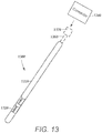
- FIG. 13 illustrates one embodiment of a device 1300 for brain stimulation.
- the device includes a lead 1310, segmented electrodes 1320, a connector 1340 for connection of the electrodes to a control unit, and a stylet 1360 for assisting in insertion and positioning of the lead in the patient's brain.
- the stylet 1360 can be made of a rigid material. Examples of suitable materials include tungsten, stainless steel, or plastic.
- the stylet 1360 may have a handle 1370 to assist insertion into the lead, as well as rotation of the stylet and lead.
- the connector 1340 fits over the proximal end of the lead 1310, preferably after removal of the stylet 1360.
- access to the desired position in the brain can be accomplished by drilling a hole in the patient's skull or cranium with a crania! drill (commonly referred to as a burr), and coagulating and incising the dura mater, or brain covering.
- the lead 1310 can be inserted into the cranium and brain tissue with the assistance of the stylet 1360.
- the lead can be guided to the target location within the brain using, for example, a stereotactic frame and a microdrive motor system.
- the microdrive motor system can be fully or partially automatic.
- the microdrive motor system may be configured to perform one or more the following actions (alone or in combination); insert the lead, retract the lead, or rotate the lead.
- measurement devices coupled to the muscles or other tissues stimulated by the target neurons or a unit responsive to the patient or clinician can be coupled to the control unit or microdrive motor system.
- the measurement device, user, or clinician can indicate a response by the target muscles or other tissues to the stimulation or recording electrode(s) to further identify the target neurons and facilitate positioning of the stimulation electrode(s).
- a measurement device can be used to observe the muscle and indicate changes in tremor frequency or amplitude in response to stimulation of neurons.
- the patient or clinician may observe the muscle and provide feedback.
- the lead 1310 for deep brain stimulation can include stimulation electrodes, recording electrodes, or both.
- the lead is rotatable so that the stimulation electrodes can be aligned with the target neurons after the neurons have been located using the recording electrodes.
- Stimulation electrodes may be disposed on the circumference of the lead to stimulate the target neurons. Stimulation electrodes may be ring-shaped so that current projects from each electrode equally in every direction at any given length along the axis of the lead. To achieve current steering, segmented electrodes can be utilized additionally or alternatively. Though the following description discusses stimulation electrodes, it will be understood that all configurations of the stimulation electrodes discussed may be utilized in arranging recording electrodes as well.
- radially segmented electrode arrays have been developed to provide superior radial selectivity of current.
- Radially segmented electrode arrays are useful for deep brain stimulation because the target structures in the deep brain are often not symmetric about the axis of the distal electrode array.
- a target may be located on one side of a plane running through the axis of the lead.
- a target may be located at a plane that is offset at some angle from the axis of the lead.
- radially segmented electrode arrays may be useful for selectively simulating tissue.
- Figure 1A illustrates one embodiment of a lead 100 for brain stimulation.
- the device includes a lead body 110, one or more ring electrodes 120, and a plurality of segmented electrodes 130.
- the lead body 110 can be formed of a biocompatible, non-conducting material such as, for example, a polymeric material. Suitable polymeric materials include, but are not limited to, silicone, polyurethanes, polyether polyurethane, polycarbonate polyurethane, or silicone-polyurethane copolymer.
- the lead may be in contact with body tissue for extended periods of time.
- the lead has a cross-sectional diameter of no more than 1.5 mm and may be in the range of 0.75 to 1.5 mm.
- the lead has a length of at least 10 cm and the length of the lead may be in the range of 25 to 70 cm.
- Stimulation electrodes may be disposed on the lead body 110. These stimulation electrodes may be made using a rnetal, alloy, conductive oxide, or any other suitable conductive material. Examples of suitable materials include, but are not limited to, platinum, iridium, platinum iridium alloy, stainless steel, titanium, or tungsten. Preferably, the stimulation electrodes are made of a material that is biocompatible and does not substantially corrode under expected operating conditions in the operating environment for the expected duration of use.
- any of the electrodes can be used as an anode or cathode and carry anodic or cathodic current.
- an electrode might be an anode for a period of time and a cathode for a period of time.
- the identity of a particular electrode or electrodes as an anode or cathode might be fixed.
- the lead contains a plurality of segmented electrodes 130. Any number of segmented electrodes 130 may be disposed on the lead body 110. In some embodiments, the segmented electrodes 130 are grouped in sets of segmented electrodes, each set disposed around the circumference of the lead at or near a particular longitudinal position.
- the lead may have any number of sets of segmented electrodes. In at least some embodiments, the lead has one, two, three, four, five, six, seven, or eight sets of segmented electrodes. In at least some embodiments, each set of segmented electrodes contains the same number of segmented electrodes 130. In some embodiments, each set of segmented electrodes contains three segmented electrodes 130.
- each set of segmented electrodes contains two, four, five, six, seven or eight segmented electrodes.
- the segmented electrodes 130 may vary in size and shape. For example, in FIG. 1B , the segmented electrodes 130 are shown as portions of a ring or curved rectangular portions. In some other embodiments, the segmented electrodes 130 are curved square portions. The shape of the segmented electrodes 130 may also be substantially triangular, diamond-shaped, oval, circular or spherical. In some embodiments, the segmented electrodes 130 are all of the same size, shape, diameter, width or area or any combination thereof. In some embodiments, the segmented electrodes of each set (or even all segmented electrodes) may be identical in size and shape.
- each set of segmented electrodes 130 may be disposed around the circumference of the lead body 110 to form a substantially or approximately cylindrical shape around the lead body 110.
- the spacing of the segmented electrodes 130 around the circumference of the lead body 110 may vary.
- equal spaces, gaps or cutouts are disposed between each segmented electrodes 130 around the circumference of the lead body 110.
- the spaces, gaps or cutouts between segmented electrodes may differ in size or shape.
- the spaces, gaps, or cutouts between segmented electrodes may be uniform for a particular set of segmented electrodes or for all sets of segmented electrodes.
- the segmented electrodes 130 may be positioned in irregular or regular intervals around the lead body 110.
- Stimulation electrodes in the form of ring electrodes 120 may be disposed on any part of the lead body 110, usually near a distal end of the lead.
- FIG. 1A illustrates a portion of a lead having one ring electrode. Any number of ring electrodes may be disposed along the length of the lead body 110.
- the lead body may have one ring electrode, two ring electrodes, three ring electrodes or four ring electrodes. In some embodiments, the lead will have five, six, seven or eight ring electrodes. Other embodiments do not include ring electrodes.
- the ring electrodes 120 are substantially cylindrical and wrap around the entire circumference of the lead body 110. In some embodiments, the outer diameter of the ring electrodes 120 is substantially equal to the outer diameter of the lead body 110. Furthermore, the width of ring electrodes 120 may vary according to the desired treatment and the location of the target neurons. In some embodiments the width of the ring electrode 120 is less than or equal to the diameter of the ring electrode 120. In other embodiments, the width of the ring electrode 120 is greater than the diameter of the ring electrode 120.
- Conductors that attach to or from the ring electrodes 120 and segmented electrodes 130 also pass through the lead body 110. These conductors may pass through the material of the lead or through a lumen defined by the lead. The conductors are presented at a connector for coupling of the electrodes to a control unit (not shown).
- the stimulation electrodes correspond to wire conductors that extend out of the lead body 110 and are then trimmed or ground down flush with the lead surface.
- the conductors may be coupled to a control unit to provide stimulation signals, often in the form of pulses, to the stimulation electrodes.
- FIG. 1B is a schematic perspective view of another embodiment of a lead having a plurality of segmented electrodes, As seen in FIG. 1B , the plurality of segmented electrodes 130 may be arranged in different orientations relative to each other. In contrast to FIG. 1A , where the three sets of segmented electrodes are aligned along the length of the lead body 110, FIG. 1B displays another embodiment in which the three sets of segmented electrodes 130 are staggered. In at least some embodiments, the sets of segmented electrodes are staggered such that no segmented electrodes are aligned along the length of the lead body 110. In some embodiments, the segmented electrodes may be staggered so that at least one of the segmented electrodes is aligned with another segmented electrode of a different set, and the other segmented electrodes are not aligned.
- segmented electrodes 130 may be disposed on the lead body 110 in any number of sets.
- FIGS. 1A and 1B illustrates embodiments including three sets of segmented electrodes. These three sets of segmented electrodes 130 may be disposed in different configurations. For example, three sets of segmented electrodes 130 may be disposed on the distal end of the lead body 110, distal to a ring electrode 120. Alternatively, three sets of segmented electrodes 130 may be disposed proximal to a ring electrode 120. By varying the location of the segmented electrodes 130, different coverage of the target neurons may be selected.
- a specific configuration may be useful if the physician anticipates that the neural target will be closer to the distal tip of the lead body 110, while another arrangement may be useful if the physician anticipates that the neural target will be closer to the proximal end of the lead body 110.
- the ring electrodes 120 alternate with sets of segmented electrodes 130.
- ring electrodes 120 and segmented electrodes 130 may be disposed on the lead.
- the segmented electrodes are arranged in sets.
- a lead may include a first ring electrode 120. two sets of segmented electrodes, each set formed of three segmented electrodes 130, and a final ring electrode 120 at the end of the lead.
- This configuration may simply be referred to as a 1-3-3-1 configuration. It may be useful to refer to the electrodes with this shorthand notation.
- Other eight electrode configurations include, for example, a 2-2-2-2 configuration, where four sets of segmented electrodes are disposed on the lead, and a 4-4 configuration, where two sets of segmented electrodes, each having four segmented electrodes 130 are disposed on the lead.
- the lead will have 16 electrodes. Possible configurations for a 16-electrode lead include, but are not limited to 4-4-4-4, 8-8, 3-3-3-3-3-1 (and all rearrangements of this configuration), and 2-2-2-2-2-2-2-2.
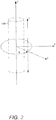
- FIG. 2 is a schematic diagram to illustrates radial current steering along various electrode levels along the length of a lead. While conventional lead configurations with ring electrodes are only able to steer current along the length of the lead (the z-axis), the segmented electrode configuration is capable of steering current in the x-axis, y-axis as well as the z-axis. Thus, the centroid of stimulation may be steered in any direction in the three-dimensional space surrounding the lead body 110.
- the radial distance, r, and the angle ⁇ around the circumference of the lead body 110 may be dictated by the percentage of anodic current (recognizing that stimulation predominantly occurs near the cathode, although strong anodes may cause stimulation as well) introduced to each electrode as will be described in greater detail below.
- the configuration of anodes and cathodes along the segmented electrodes 130 allows the centroid of stimulation to be shifted to a variety of different locations along the lead body 110.
- the centroid of stimulation can be shifted at each level along the length of the lead.
- the use of multiple sets of segmented electrodes 130 at different levels along the length of the lead allows for three-dimensional current steering.
- the sets of segmented electrodes 130 are shifted collectively (i.e. the centroid of simulation is similar at each level along the length of the lead).
- each set of segmented electrodes 130 is controlled independently.
- Each set of segmented electrodes may contain two, three, four, five, six, seven, eight or more segmented electrodes. It will be understood that different stimulation profiles may be produced by varying the number of segmented electrodes at each level.
- each set of segmented electrodes includes only two segmented electrodes, uniformly distributed gaps (inability to stimulate selectively) may be formed in the Stimulation profile.
- at least three segmented electrodes 130 are utilized to allow for true 360° selectivity.
- a lead having segmented electrodes may provide several advantages.
- the lead may provide for more directed simulation, as well as less “wasted” stimulation (i.e. stimulation of regions other than the target region).
- less “wasted” stimulation i.e. stimulation of regions other than the target region.
- side effects may be reduced.
- the battery in an implantable pulse generator may last for a longer period of time between recharging.
- measurement devices coupled to the muscles or other tissues stimulated by the target neurons or a unit responsive to the patient or clinician can be coupled to the control unit or microdrive motor system.
- the measurement device, user, or clinician can indicate a response by the target muscles or other tissues to the stimulation or recording electrodes to further identify the target neurons and facilitate positioning of the stimulation electrodes.
- a measurement device can be used to observe the muscle and indicate changes in tremor frequency or amplitude in response to stimulation of neurons.
- the patient or clinician may observe the muscle and provide feedback.
- Radially segmented electrode arrays may be manufactured in a variety of ways, for example, by embedding or coupling conductive portions in a lead body.
- a disk having an inner cavity may be used to form a radially segmented electrode array.
- the disk may define various lumens for housing conductors and for facilitating attachment to the lead body.
- Radially segmented electrode arrays may also be formed by disposing electrodes in an electrode frame or in a lumen defined by the lead body.
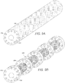
- FIG. 3A is a schematic perspective view of one embodiment of a pre-electrode disk 300.
- the pre-electrode may be formed of conductor such as a metal, alloy, conductive oxide, or any other suitable conductive material.
- the pre-electrode 300 is formed of platinum, platinum-indium, iridium, 316L stainless steel, tantalum, nitinol or a conductive polymer. The shape and size of the pre-electrode 300 may be modified. As seen in FIG. 3A , the pre-electrode 300 may be formed in the shape of a disk.
- the pre-electrode 300 is formed of a substantially cylindrical member having a diameter larger than the desired final diameter of the lead. It will be understood that the pre-electrode 300 need not be substantially cylindrical, but may also be formed in the shape of a cube (see e.g., FIG. 3B ), or any other polyhedron. In such embodiments, a cylindrical lead may be obtained by grinding (e.g., centerless grinding), machining, or ablating the outer diameter of the pre-electrode 300.
- the pre-electrode 300 defines a divider 310.
- the divider 310 may be formed of any shaped passage that extends through the longitudinal axis of the pre-electrode 300. As seen in FIG. 3A , in some embodiments, the divider 310 is formed of a central passage having three partitioning arms. The three partitioning arms will divide the pre-electrode 300 into three segmented electrodes as will be described with reference to FIGS. 4 , 5A and 5B . It will be understood that the size and shape of the divider 310 may be varied and that the divider 310 may be formed in any pattern suitable for dividing the pre-electrode 300 into a desired number of partitions. In some embodiments, the divider also includes a central lumen for passage of a stylet.
- the pre-electrode 300 may include one or more conductor lumens 320.
- the conductor lumen 320 may be any lumen, hole, or passage that extends through the longitudinal axis of the pre-electrode 300.
- the pre-electrode 300 includes one, two, three, four, five, six, eight, ten, or twelve conductor lumens 320.
- the pre-electrode 300 includes one conductor lumen 320 for each segmented electrode that will be formed from the pre-electrode 300.
- a divider 310 is configured such that three segmented electrodes will be formed from the pre-electrode 300, then three conductor lumens 320 may be formed, one for each segmented electrode.
- the size of the conductor lumens 320 may be varied as needed.
- the conductor lumens 320 are defined to have a circular cross-section corresponding to the cross-section of conductors that will be coupled to the electrodes.
- the cross-section of the conductor lumens 320 are the same size and shape.
- the conductor lumens 320 may be formed in different shapes or sizes.
- the conductor lumen 320 may have a cross-section that is in the shape of a square, a rectangle, an oval, or a triangle.
- the pre-electrode 300 includes one or more fixing lumens 330.
- the fixing lumen 330 may be any lumen, hole, or passage that extends through the longitudinal axis of the pre-electrode 300. In some embodiments, the fixing lumen 330 only partially extends through the longitudinal axis of the electrode 300. In at least some other embodiments, the fixing lumen 330 is defined as a through hole, a passage that extends through the full length of the pre-electrode 300.
- the fixing lumen 330 may be similar to the conductor lumen 320 in shape and size. The fixing lumen 330 may also be of different shape or size than the conductor lumen 320. In some embodiments, the fixing lumen 330 has a circular cross-section. As seen in FIG. 3A , the fixing lumen 330 may have a smaller cross-section than the conductor lumen 320.
- FIG. 3B is a schematic perspective view of a second embodiment of a pre-electrode 300.
- the pre-electrode 300 of FIG. 3B includes fixing lumens 330 and conductor lumens 320.
- the pre-electrode 300 also includes a divider 310 with four partitioning arms.
- a divider 310 may include any number of partitioning arms such as three, four, five, six, eight, ten, or twelve partitioning arms.
- a single pre-electrode 300 may be used to form four segmented electrodes.
- the pre-electrode 300 is formed in the shape of a cube.
- the cube-shaped pre-electrode 300 may be further processed to form segmented electrodes having the desired shape and size.
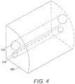
- FIG. 4 is a schematic perspective view of one embodiment of a segmented electrode 400.
- the segmented electrode 400 may be the result of partitioning the pre-electrode 300 of FIG. 3A along divider 310.
- each segmented electrode 400 after partitioning the pre-electrode 300, each segmented electrode 400 includes a single fixing lumen 330 and a single conductor lumen 320. It will be understood that the pre-electrodes 300 and segmented electrodes 400 may be configured such that each segmented electrode 400 includes any number of faxing lumen 330 or conductor lumens 320.
- FIG. 5A is a schematic perspective view of one embodiment of a pre-electrode 300 before grinding.
- the pre-electrode 300 of FIG. 5A is disk-shaped, the pre-electrode 300 may be formed of any suitable shape.
- the pre-electrode 300 includes a pluratity of fixing lumens 330.
- the fixing lumens 330 allow for coupling or locking portions of the pre-electrode 300 to the lead body 110 (not shown) by reflowing a portion of the lead body 110 to allow it to pass through the fixing lumens 330.
- additional fixing material similar to the lead body 110 is disposed within the fixing lumen 330.
- the fixing material may be composed of the same material or any other material capable of reflowing with the lead body 110.
- portions of the pre-electrode 300 are further bonded to the lead body 110 with a potting agent or adhesive such as epoxy.
- FIG. 5A further illustrates conductors 510 being disposed through the conductor lumens 320.
- the conductors 510 have a diameter corresponding to the diameter of the conductor lumens 320.
- a conductor 510 may be coated or wrapped with an insulator 520.
- the conductors 510 may also include ablated portions 530.
- the ablated portions 530 allow for electrical coupling between the conductor 510 and the segmented electrode.
- the portions of the conductors 510 are disposed within the conductor lumens 320 of the pre-electrode 300 then welded to a portion of the pre-electrode 300. It will be understood than any other method suitable for electrically coupling a pre-electrode 300 to a conductor 510 may be used.
- the pre-electrodes 300 may be formed larger in diameter than the lead body 110. Furthermore, the pre-electrodes 300 are yet undivided. In some embodiments, it may be useful or desirable to grind down the pre-electrodes 300 to an appropriate diameter. After the pre-electrodes 300 have been ground down to the same level as the lead body 110. the lead 100 is isodiametric, having substantially the same diameter in all directions. The result is a substantially cylindrical lead 100 that is suitable for deep brain stimulation. Grinding down the pre-electrodes 300 is also capable of forming segmented electrodes 400 from the pre-electrodes 300. Preferably, the pre-electrodes are ground after the pre-electrodes are fixed within the lead and coupled to the conductors.
- FIG. 5B is a schematic perspective view of the pre-electrode 300 of FIG. 5A after grinding.
- grinding the pre-electrode 300 results in grinding portions of the pre-electrode down to the divider 310, thus forming separate segmented electrodes 400.
- three segmented electrodes 400 are formed at one level of the lead body 110.
- a plurality of pre-electrodes 300 may be disposed at predetermined longitudinal levels of the lead body 110 to create leads having variable stimulation profiles.
- the segmented electrodes 400 are electrically insulated from one another so that the stimulation directed to each segmented electrode 400 is independently-controlled.
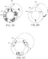
- FIG. 6A illustrates an electrode frame 610 capable of housing a plurality of segmented electrodes.
- the electrode frame 610 may be formed of a biocompatible, non-conducting material such as, for example, a polymeric material. Suitable polymeric materials include, but are not limited to, polyetheretherketone (PEEK), polytetrafluoroethylene (e.g., TeflonTM), polyimide, silicone, polyurethanes, polyether polyurethane, polycarbonate polyurethane, and silicone-polyurethane copolymer.
- PEEK polyetheretherketone
- TeflonTM polytetrafluoroethylene
- silicone silicone
- the electrode frame 610 defines a plurality of electrode chambers 620 for accepting a plurality of segmented electrodes.
- the embodiment of FIG. 6A illustrates an electrode frame 610 having three electrode chambers 620. It will be understood that the electrode frame 610 may include any number of electrode chambers 620. In some embodiments, the electrode frame 610 includes one, two, three, four, five, six, seven, eight, nine, ten, twelve, fourteen or sixteen electrode chambers 620.
- the electrode chambers 620 may also be defined to house segmented electrodes of the same or different shape or size. In at least some embodiments, the electrode chambers 620 are of the same shape and size. In some embodiments, the electrode chambers 620 fully enclose the segmented electrodes.
- the electrode chambers 620 may be equally spaced about the electrode frame 610. As illustrated, in some embodiments, the electrode frame 610 is C-shaped with an opening 630 configured for coupling the electrode frame 610 to a tubing as will be described in greater detail with reference to FIG. 10A .
- the electrode frame 610 may also include longitudinally extending grooves 640 on the interior of the electrode frame 610. The grooves 640 may be configured to house conductors (not shown).
- FIGS. 6B and 6C are schematic perspective views of a second and third embodiment of an electrode frame 610.
- the electrode frames 610 may include various electrode chambers 620 with a variety of different shapes.
- the electrode frames 610 may be formed to house different-shaped segmented electrodes.
- the electrode frame 610 lacks an opening 636, but is formed slightly larger in diameter so as to be press fit over the lead body.
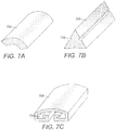
- the segmented electrodes 710 may be formed of platinum, platinum-iridium, iridium, 316L stainless steel, tantalum, nitinol, a conductive polymer, or any other suitable conductive material.
- FIG. 7A is a schematic perspective view of one embodiment of a segmented electrode 710 corresponding to the electrode frame 610 of FIG. 6A , formed of an elongate member with an arched cross-section.
- FIG. 7B is a schematic perspective view of a second embodiment of a segmented electrode 710 corresponding to the electrode frame 610 of FIG. 6B .
- the segmented electrode 710 of FIG. 7B has a triangular cross-section.
- FIG. 7A is a schematic perspective view of one embodiment of a segmented electrode 710 corresponding to the electrode frame 610 of FIG. 6A , formed of an elongate member with an arched cross-section.
- FIG. 7B is a schematic perspective view of a second embodiment of a segmente
- FIG. 7C is a schematic perspective view of a third embodiment of a segmented electrode 710 corresponding to the electrode frame 610 of FIG. 6C .
- the segmented electrodes 710 may be formed in a variety of shapes and sizes.
- the segmented electrodes 710 are formed of elongate members having a circular, ovoid, rectangular, square, hexagonal, star-shaped, cruciform, trapezoidal, or a patterned cross-section (e.g. the cross-section shown in FIG. 7C ).
- the segmented electrodes 710 include fastening features 720 to aid in fastening them to the electrode frame 610.
- the fastening feature 720 may be any of a hole, key, seam, neck, shoulder, or rib.
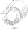
- FIG. 8 is a schematic perspective view of the segmented electrodes 710 of FIG. 7A being inserted into the electrode chambers 620 of the electrode frame 610 of FIG. 6A .
- the segmented electrode 710 may be press fit into the electrode frame 610.
- Other methods may be used to further affix or couple the segmented electrode 710 to the electrode frame 610.
- a potting agent or adhesive may be used to affix the segmented electrode 710 to the electrode frame 610.
- fastening features 720 which correspond to the shape of the electrode chambers 620 are useful for maintaining a proper fit between an electrode frame 610 and a segmented electrode 710.
- FIG. 9A is a schematic perspective view of one embodiment of a multi-lumen tubing 900.
- the multi-lumen tubing 900 may be formed of any material or combination of materials used in forming a lead body.
- the multi-lumen tubing 900 may define a central passage 910 configured to receive a stylet or other insertion instrument. Though the central passage 910 is illustrated as a passage having a circular cross-section, any shaped central passage 910 may be formed. In some embodiments, the central passage 910 has a cross-section corresponding to the cross-section of a stylet.
- the multi-lumen tubing 900 may define a plurality of longitudinally disposed conductor lumens 930, Any number of conductor lumens 930 may be defined within the multi-lumen tubing 900. In some embodiments, one, two, three, four, five, six, seven, eight, nine, ten, twelve or more conductor lumens 930 may be defined by the multi-lunlen tubing 900. In some embodiments, the number of conductor lumens 930 corresponds to the number of electrodes that will be disposed on the tubing 900.
- FIG. 9B is a schematic perspective view of the multi-lumen tubing 900 of FIG. 9A after ablating portions of the tubing 900.
- any method may be used for removing sections of muiti-iumen tubing 900.
- portions of the multi-lumen tubing 900 may be ground down to form slots 920.
- slots 920 may also be formed by ablating the outer layer of the multi-lumen tubing 900 using, for example, laser ablation. The resulting slots 920 may have dimensions corresponding to the dimensions of the electrode frame 610, so that the electrode frame 610 is coupleable to the multi-lumen, tubing 900.
- the electrode frames 610 may be coupled to the multi-lumen tubing 900.
- FIG. 10A is a schematic perspective view of one embodiment of a lead consisting of a muiti-lumen tubing 900 and electrodes frames 610 disposed on the tubing 900.
- the electrode frame 610 is flexible and configured so that the opening 630 of the electrode frame 610 allows coupling to the multi-lumen tubing 900.
- the electrode frames 610 are configured to slide over the tubing 900. After coupling the electrode frames 610 and the multi-lumen tubing 900, the tubing 900 and the electrode frame 610 may be reflowed to form a lead 1000.
- the tubing 900 and electrode frames 610 are configured so that during the reflow process, material is reflowed through fixing lumens. By reflowing material through the fixing lumen, a more reliable lead 1000 may be formed that is less prone to breakage and failure. Individual conductors may be disposed through conductor lumens 930 and the grooves 640 and welded to the individual segmented electrodes 710.
- portions of the outer surface of the electrode frame 610 may also be removed (e.g., by ablation, grinding, and the like) to expose the segmented electrode 710.
- the outer surfaces of the electrode frames 610 may be removed in any pattern as desired.
- the outer surface of the electrode frame 610 is removed at one or more positions corresponding to each of the segmented electrodes 710 that are housed within.
- an isodiametric lead is formed by grinding the outer surface of the electrode frame 610 and the lead body to the same diameter.
- the outer portion of the electrode chamber 620 is removed to form an electrode cavity and the electrodes 710 are exposed at the surface of the lead.
- each segmented electrode 710 is electrically coupled to an independent conductor (not shown) disposed within one of the lumens 930 so that each segmented electrode 710 may be independently activated.
- FIG. 11A is a schematic perspective view of one embodiment of a segmented electrode 1110.
- the segmented electrode 1110 may be similar to those described in other embodiments.
- the segmented electrode 1110 is a rectangular portion having legs and includes flanges 1120.
- each segmented electrode 1110 includes one flange 1120 on each side, though it will be understood that the segmented electrode 1110 may include any number of flanges 1120.
- FIX. 11B is a schematic perspective view of one embodiment of the segmented electrode 1110 of FIG. 11A disposed in a carrier 1150.
- the carrier 1150 may be a tray-like member formed of any suitable insulative material capable of housing the segmented electrodes 1110. Suitable materials for the carrier 1150 include, but are not limited to polymers (including plastics), composite materials, and the like. In some embodiments, the carrier 1150 is formed of silicone.
- the carrier 1150 includes apertures 1160 for receiving the segmented electrodes 1110. In some embodiments, the apertures 1160 are formed of the same or different shapes and sizes. In some embodiments, the apertures 1160 correspond to the size and shape of the segmented electrodes 1110. Furthermore, the apertures 1160 may be formed in any pattern along the surface of the carrier 1150.
- the carrier 1150 may also include side holes 1170 to allow for the passage of conductors (not shown) to the segmented electrodes 1110.
- each aperture 1160 corresponds to one or more side holes 1170.
- the side holes 1170 may be formed in any edge or face of the carrier 1150. In some embodiments, as seen in FIG. 11B , the side holes 1170 are aligned along one edge of the carrier 1150. It will be understood that any number of side holes 1170 may be formed in the carrier 1150 in any pattern or alignment, such as in multiple rows.
- the segmented electrodes 1110 may be press fit into the apertures 1160 of the carrier 1150.
- the segmented electrodes 1110 are locked in place by the flanges 1120 on the sides.
- the flanges 1120 may be configured to mate with a side of the apertures 1160.
- the carrier 1150 may be wrapped around a mandrel and reflowed to form a lead as seen in FIG. 11C .
- a tubing 1200 similar to that of the multi-lumen tubing 900 is provided.
- the tubing 1200 may be provided with a plurality of conductor lumens 1220.
- the tubing 1200 may also include a central passage 1210 configured for receiving an insertion instrument such as a stylet.
- Pre-welded electrode tubes 1250 may be disposed within the conductor lumens 1220.
- FIG. 12A is a schematic perspective view of one embodiment of a tubing 1200 having electrode tubes 1250.
- the electrode tubes 1250 may be short in length and inserted only in conductor lumens on sides of the multi-lumen tubing 1200 where stimulation is desired.
- electrodes tubes 1250 are inserted only at the extremities of the multi-lumen tubing 1200.
- the electrode tubes 1250 may be press fit within the multi-lumen tubing 1200 to avoid slippage during manufacture and usage.
- additional methods may be used to enhance coupling between the electrodes tubes 1250 and the multi-lumen tubing 1200, such as, for example, the use of epoxy within the conductor lumens 1220.
- the electrode tubes 1250 have a groove 1270 that may be useful in coupling the electrode tube 1250 to the tubing 1200.
- the groove 1270 may be longitudinally positioned along the electrode tube 1250.
- the conductor lumen 1220 may be defined to have a cross-sectional shape that will aid in fastening the electrode tube 1250 to the tubing 1200. It will be understood that any number of grooves 1270 may be positioned on the electrode tube 1250.
- the electrode tubes 1250 disposed within the multi-lumen tubing 1200 may be used to expose portions of the electrode tubes 1250 by removing portions of the outer surface of the tubing 1200. As seen in FIG. 12A , the locations of ablation 1260 may be chosen in any pattern as desired.
Landscapes
- Health & Medical Sciences (AREA)
- Neurology (AREA)
- Neurosurgery (AREA)
- Psychology (AREA)
- Cardiology (AREA)
- Heart & Thoracic Surgery (AREA)
- Engineering & Computer Science (AREA)
- Biomedical Technology (AREA)
- Nuclear Medicine, Radiotherapy & Molecular Imaging (AREA)
- Radiology & Medical Imaging (AREA)
- Life Sciences & Earth Sciences (AREA)
- Animal Behavior & Ethology (AREA)
- General Health & Medical Sciences (AREA)
- Public Health (AREA)
- Veterinary Medicine (AREA)
- Electrotherapy Devices (AREA)
Claims (12)
- Procédé de fabrication d'un dispositif pour la stimulation du cerveau, le procédé comprenant :la formation d'un corps de conduit (110) ayant une section d'extrémité distale ;le couplage d'au moins une pré-électrode (300) à la section d'extrémité distale du corps de conduit, la pré-électrode définissant un diviseur (310) avec plusieurs bras de partition, et ayant plusieurs lumens de fixation (330) ;l'élimination d'une portion de la pré-électrode alignée avec les bras de partition pour diviser la pré-électrode en plusieurs électrodes segmentées (400), chacune des plusieurs électrodes segmentées définissant au moins un des plusieurs lumens de fixation au moins partiellement disposés à travers l'électrode segmentée ; etl'introduction d'un matériau à travers le au moins un lumen de fixation pour coupler les plusieurs électrodes segmentées au corps de conduit.
- Procédé selon la revendication 1, dans lequel le au moins un lumen de fixation est une perforation.
- Procédé selon la revendication 1, dans lequel chacune de la au moins une électrode segmentée définit de plus au moins un lumen conducteur.
- Procédé selon la revendication 3, comprenant de plus la disposition d'au moins un conducteur dans chacun du au moins un lumen conducteur.
- Procédé selon la revendication 1, dans lequel l'introduction d'un matériau comprend le reflux d'une portion du corps de conduit à travers le au moins un lumen de fixation.
- Procédé selon la revendication 1, dans lequel le diviseur est un passage façonné qui s'étend à travers un axe longitudinal de la pré-électrode, le diviseur étant formé d'un passage central avec les plusieurs bras de partition s'étendant en s'éloignant du passage central dans différentes directions.
- Procédé selon la revendication 1, dans lequel chacun des plusieurs lumens de fixation est une perforation s'étendant entièrement à travers une longueur longitudinale de la pré-électrode.
- Procédé selon la revendication 3, dans lequel chacun du au moins un lumen conducteur est une perforation s'étendant entièrement à travers une longueur longitudinale de la pré-électrode.
- Procédé selon la revendication 8, dans lequel chacun des plusieurs lumens de fixation est une perforation s'étendant entièrement à travers une longueur longitudinale de la pré-électrode et dans lequel chacun des plusieurs lumens de fixation présente une section transversale inférieure à chacune du au moins un lumen conducteur.
- Procédé selon la revendication 1, dans lequel l'élimination d'une portion de la pré-électrode comprend le broyage de la pré-électrode pour réduire un diamètre de la pré-électrode et former par-là les plusieurs électrodes segmentées.
- Procédé selon la revendication 1, dans lequel le matériau est introduit à travers le au moins un lumen de fixation avant l'élimination de la portion de la pré-électrode alignée avec les bras de partition.
- Procédé selon la revendication 1, dans lequel la pré-électrode présente les plusieurs lumens de fixation avant l'élimination de la portion de la pré-électrode alignée avec les bras de partition.
Applications Claiming Priority (2)
| Application Number | Priority Date | Filing Date | Title |
|---|---|---|---|
| US35652910P | 2010-06-18 | 2010-06-18 | |
| PCT/US2011/040229 WO2011159631A2 (fr) | 2010-06-18 | 2011-06-13 | Réseau d'électrodes ayant des électrodes intégrées et procédés de fabrication de celui-ci |
Publications (2)
| Publication Number | Publication Date |
|---|---|
| EP2582425A2 EP2582425A2 (fr) | 2013-04-24 |
| EP2582425B1 true EP2582425B1 (fr) | 2018-04-04 |
Family
ID=44454803
Family Applications (1)
| Application Number | Title | Priority Date | Filing Date |
|---|---|---|---|
| EP11726632.0A Active EP2582425B1 (fr) | 2010-06-18 | 2011-06-13 | Procédé de fabrication de réseau d'électrodes ayant des électrodes intégrées |
Country Status (5)
| Country | Link |
|---|---|
| US (2) | US8868206B2 (fr) |
| EP (1) | EP2582425B1 (fr) |
| JP (1) | JP5793190B2 (fr) |
| CA (1) | CA2798165A1 (fr) |
| WO (1) | WO2011159631A2 (fr) |
Families Citing this family (197)
| Publication number | Priority date | Publication date | Assignee | Title |
|---|---|---|---|---|
| US7860570B2 (en) | 2002-06-20 | 2010-12-28 | Boston Scientific Neuromodulation Corporation | Implantable microstimulators and methods for unidirectional propagation of action potentials |
| US7583999B2 (en) | 2006-07-31 | 2009-09-01 | Cranial Medical Systems, Inc. | Multi-channel connector for brain stimulation system |
| US8321025B2 (en) | 2006-07-31 | 2012-11-27 | Cranial Medical Systems, Inc. | Lead and methods for brain monitoring and modulation |
| EP2134413B1 (fr) | 2007-03-19 | 2016-09-21 | Boston Scientific Neuromodulation Corporation | Procédés et appareil de fabrication de fils à partir de conducteurs et configurations de fil souple concernées |
| AU2008229465B2 (en) | 2007-03-19 | 2013-08-22 | Boston Scientific Neuromodulation Corporation | MRI and RF compatible leads and related methods of operating and fabricating leads |
| US8359107B2 (en) | 2008-10-09 | 2013-01-22 | Boston Scientific Neuromodulation Corporation | Electrode design for leads of implantable electric stimulation systems and methods of making and using |
| EP3520855B1 (fr) | 2009-04-16 | 2024-05-29 | Boston Scientific Neuromodulation Corporation | Orientation d'un courant de stimulation cérébrale profonde au moyen d'électrodes séparées |
| US8875391B2 (en) | 2009-07-07 | 2014-11-04 | Boston Scientific Neuromodulation Corporation | Methods for making leads with radially-aligned segmented electrodes for electrical stimulation systems |
| US8887387B2 (en) | 2009-07-07 | 2014-11-18 | Boston Scientific Neuromodulation Corporation | Methods of manufacture of leads with a radially segmented electrode array |
| US8788063B2 (en) | 2009-11-30 | 2014-07-22 | Boston Scientific Neuromodulation Corporation | Electrode array having a rail system and methods of manufacturing the same |
| US8874232B2 (en) | 2009-11-30 | 2014-10-28 | Boston Scientific Neuromodulation Corporation | Electrode array having concentric split ring electrodes and methods of making the same |
| US8391985B2 (en) | 2009-11-30 | 2013-03-05 | Boston Scientific Neuromodulation Corporation | Electrode array having concentric windowed cylinder electrodes and methods of making the same |
| US8295944B2 (en) | 2009-11-30 | 2012-10-23 | Boston Scientific Neuromodulation Corporation | Electrode array with electrodes having cutout portions and methods of making the same |
| JP5750506B2 (ja) * | 2010-03-23 | 2015-07-22 | ボストン サイエンティフィック ニューロモデュレイション コーポレイション | 脳刺激のための装置 |
| EP2582425B1 (fr) | 2010-06-18 | 2018-04-04 | Boston Scientific Neuromodulation Corporation | Procédé de fabrication de réseau d'électrodes ayant des électrodes intégrées |
| WO2012009181A2 (fr) | 2010-07-16 | 2012-01-19 | Boston Scientific Neuromodulation Corporation | Systèmes et procédés pour la direction radiale de groupements d'électrodes |
| US8583237B2 (en) | 2010-09-13 | 2013-11-12 | Cranial Medical Systems, Inc. | Devices and methods for tissue modulation and monitoring |
| CA2810824A1 (fr) | 2010-09-21 | 2012-03-29 | Boston Scientific Neuromodulation Corporation | Systemes et procedes permettant de realiser et d'utiliser des electrodes segmentees alignees de facon radiale pour des fils de systemes d'electrostimulation |
| US8862242B2 (en) | 2010-12-23 | 2014-10-14 | Boston Scientific Neuromodulation Corporation | Methods for making leads with segmented electrodes for electrical stimulation systems |
| US8700179B2 (en) | 2011-02-02 | 2014-04-15 | Boston Scientific Neuromodulation Corporation | Leads with spiral of helical segmented electrode arrays and methods of making and using the leads |
| US20120203316A1 (en) | 2011-02-08 | 2012-08-09 | Boston Scientific Neuromodulation Corporation | Leads with segmented electrodes for electrical stimulation of planar regions and methods of making and using |
| EP2673042B1 (fr) | 2011-02-08 | 2019-01-09 | Boston Scientific Neuromodulation Corporation | Conducteurs à électrodes segmentées avec canal et procédés de fabrication des conducteurs |
| CA2826040A1 (fr) | 2011-02-08 | 2012-08-16 | Boston Scientific Neuromodulation Corporation | Procedes de fabrication de derivations a electrodes segmentees pour systemes de stimulation electrique |
| US8886335B2 (en) | 2011-12-07 | 2014-11-11 | Boston Scientific Neuromodulation Corporation | Implantable leads with a low profile distal portion |
| JP5908611B2 (ja) | 2012-01-26 | 2016-04-26 | ボストン サイエンティフィック ニューロモデュレイション コーポレイション | 電気刺激システムのためのリードの電極の周方向位置決めを識別するためのシステム及び方法 |
| EP2830700B1 (fr) | 2012-03-30 | 2017-09-27 | Boston Scientific Neuromodulation Corporation | Dérivations à capsules fluorescentes de rayons x pour identification d'électrode et procédés de fabrication ainsi que leur utilisation |
| US9827413B2 (en) | 2012-04-17 | 2017-11-28 | Boston Scientific Neuromodulation Corporation | Lead construction for deep brain stimulation |
| US9878148B2 (en) | 2012-04-17 | 2018-01-30 | Boston Scientific Neuromodulation Corporation | Lead with contact end conductor guide and methods of making and using |
| EP2841149B1 (fr) | 2012-04-27 | 2020-07-08 | Medtronic, Inc. | Procédé et un système pour la fabrication d'un conducteur médical moyennant un porte-électrodes |
| US20130317587A1 (en) | 2012-05-25 | 2013-11-28 | Boston Scientific Neuromodulation Corporation | Methods for stimulating the dorsal root ganglion with a lead having segmented electrodes |
| WO2013177307A1 (fr) | 2012-05-25 | 2013-11-28 | Boston Scientific Neuromodulation Corporation | Implantation percutanée d'un fil de stimulation électrique pour stimuler un ganglion de racine dorsale |
| WO2013177159A1 (fr) | 2012-05-25 | 2013-11-28 | Boston Scientific Neuromodulation Corporation | Systèmes et méthodes de stimulation électrique des tissus d'un patient sur ou autour d'une ou de plusieurs structures osseuses |
| US9919148B2 (en) | 2012-05-25 | 2018-03-20 | Boston Scientific Neuromodulation Corporation | Distally curved electrical stimulation lead and methods of making and using |
| CN104519946B (zh) | 2012-06-01 | 2016-10-19 | 波士顿科学神经调制公司 | 用于电刺激系统的具有端头电极的导线及其制造和使用方法 |
| DE102012013338B4 (de) * | 2012-07-06 | 2019-09-26 | Heraeus Deutschland GmbH & Co. KG | Verfahren zur Herstellung einer Elektrodenstruktur |
| US8897891B2 (en) | 2012-08-03 | 2014-11-25 | Boston Scientific Neuromodulation Corporation | Leads with electrode carrier for segmented electrodes and methods of making and using |
| US9415154B2 (en) | 2012-11-26 | 2016-08-16 | Boston Scientific Neuromodulation Corporation | Systems and methods for making and using an electrical stimulation system with photonic stimulation capabilities |
| US9162048B2 (en) | 2013-05-15 | 2015-10-20 | Boston Scientific Neuromodulation Corporation | Systems and methods for making and using tip electrodes for leads of electrical stimulation systems |
| CN105263567A (zh) | 2013-05-31 | 2016-01-20 | 波士顿科学神经调制公司 | 由具有对准特征的制备电极形成的分段电极引导件以及制造与使用此引导件的方法 |
| CA2911239A1 (fr) * | 2013-05-31 | 2014-12-04 | Boston Scientific Neuromodulation Corporation | Conducteurs contenant des electrodes segmentees pourvues de pattes non perpendiculaires et procedes de fabrication et d'utilisation desdits conducteurs |
| AU2014274414A1 (en) | 2013-05-31 | 2015-11-19 | Boston Scientific Neuromodulation Corporation | Leads with segmented electrodes and methods of making the leads |
| AU2014274412A1 (en) | 2013-05-31 | 2015-11-19 | Boston Scientific Neuromodulation Corporation | Segmented electrode leads formed from pre-electrodes with depressions or apertures and methods of making |
| WO2014193761A1 (fr) | 2013-05-31 | 2014-12-04 | Boston Scientific Neuromodulation Corporation | Procédé de fabrication de conducteurs d'électrodes segmentées au moyen d'un anneau amovible et conducteurs formés par celui-ci |
| EP3019232B1 (fr) | 2013-07-12 | 2019-08-21 | Boston Scientific Neuromodulation Corporation | Sondes à électrodes segmentées et procédés de fabrication des sondes |
| US9655528B2 (en) | 2013-07-15 | 2017-05-23 | Boston Scientific Neuromodulation Corporation | Systems and methods for detecting cerebrospinal-fluid pulsation using an implantable electrical stimulation device |
| JP6158440B2 (ja) | 2013-07-22 | 2017-07-05 | ボストン サイエンティフィック ニューロモデュレイション コーポレイション | 成形セグメント電極リードを製造する方法 |
| US9302113B2 (en) | 2013-07-29 | 2016-04-05 | Boston Scientific Neuromodulation Corporation | Systems and methods for identifying anode placement based on cerebrospinal fluid thickness |
| WO2015031375A1 (fr) | 2013-08-30 | 2015-03-05 | Boston Scientific Neuromodulation Corporation | Procédés de fabrication de tiges d'électrodes segmentées utilisant un support à brides |
| CN108742830A (zh) | 2013-10-28 | 2018-11-06 | 圣犹达医疗用品心脏病学部门有限公司 | 具有增强诊断能力的消融导管设计以及方法 |
| EP3077039B1 (fr) | 2013-12-02 | 2021-10-13 | Boston Scientific Neuromodulation Corporation | Procédés pour le fabrication des sondes pour la stimulation électrique avec électrodes arrangées en hélice |
| WO2015192058A1 (fr) | 2014-06-13 | 2015-12-17 | Boston Scientific Neuromodulation Corporation | Sondes comprenant des supports d'électrode pour des électrodes segmentées, et procédés de fabrication et d'utilisation |
| US9770598B2 (en) | 2014-08-29 | 2017-09-26 | Boston Scientific Neuromodulation Corporation | Systems and methods for making and using improved connector contacts for electrical stimulation systems |
| US9833622B2 (en) | 2014-09-22 | 2017-12-05 | Boston Scientific Neuromodulation Corporation | Devices and methods using a pathological frequency in electrical stimulation for pain management |
| AU2015321473B2 (en) | 2014-09-22 | 2018-02-01 | Boston Scientific Neuromodulation Corporation | Systems and methods for providing therapy using electrical stimulation to disrupt neuronal activity |
| WO2016049021A1 (fr) | 2014-09-22 | 2016-03-31 | Boston Scientific Neuromodulation Corporation | Systèmes et procédés pour appliquer un traitement au moyen d'une stimulation électrique pour interrompre l'activité neuronale |
| WO2016049023A1 (fr) | 2014-09-22 | 2016-03-31 | Boston Scientific Neuromodulation Corporation | Systèmes et procédés pour administrer une thérapie à un patient à l'aide d'une stimulation électrique intermittente |
| EP4000684B1 (fr) | 2014-09-22 | 2025-05-07 | Boston Scientific Neuromodulation Corporation | Dispositifs d'utilisation d'un spectre d'énergie ou d'une association de signaux pour la gestion de la douleur |
| US9974959B2 (en) | 2014-10-07 | 2018-05-22 | Boston Scientific Neuromodulation Corporation | Systems, devices, and methods for electrical stimulation using feedback to adjust stimulation parameters |
| US20160121103A1 (en) | 2014-11-03 | 2016-05-05 | Boston Scientific Neuromodulation Corporation | Electrical stimulation system with anchoring stylet and methods of making and using |
| US9604068B2 (en) | 2014-11-10 | 2017-03-28 | Boston Scientific Neuromodulation Corporation | Systems and methods for making and using improved connector contacts for electrical stimulation systems |
| US9561362B2 (en) | 2014-11-10 | 2017-02-07 | Boston Scientific Neuromodulation Corporation | Systems and methods for making and using improved contact arrays for electrical stimulation systems |
| US10286205B2 (en) | 2015-02-06 | 2019-05-14 | Boston Scientific Neuromodulation Corporation | Systems and methods for making and using improved contact arrays for electrical stimulation systems |
| WO2016164361A1 (fr) | 2015-04-10 | 2016-10-13 | Boston Scientific Neuromodulation Corporation | Systèmes et procédés de fabrication et d'utilisation de réseaux de contact améliorés pour des systèmes de stimulation électrique |
| CN107530542B (zh) | 2015-05-26 | 2020-10-13 | 波士顿科学神经调制公司 | 用于分析电刺激和选择或操纵激活量的系统 |
| US20160375248A1 (en) | 2015-06-29 | 2016-12-29 | Boston Scientific Neuromodulation Corporation | Systems and methods for selecting stimulation parameters based on stimulation target region, effects, or side effects |
| WO2017003947A1 (fr) | 2015-06-29 | 2017-01-05 | Boston Scientific Neuromodulation Corporation | Systèmes et procédés de sélection de paramètres de stimulation par ciblage et guidage |
| US9656093B2 (en) | 2015-07-16 | 2017-05-23 | Boston Scientific Neuromodulation Corporation | Systems and methods for making and using connector contact arrays for electrical stimulation systems |
| US10232169B2 (en) | 2015-07-23 | 2019-03-19 | Boston Scientific Neuromodulation Corporation | Burr hole plugs for electrical stimulation systems and methods of making and using |
| EP3307382A1 (fr) | 2015-08-24 | 2018-04-18 | Boston Scientific Neuromodulation Corporation | Systèmes et procédés permettant de déterminer l'orientation d'une dérivation de stimulation électrique |
| EP3297719B1 (fr) | 2015-09-01 | 2022-02-09 | Boston Scientific Neuromodulation Corporation | Détection d'orientation de câble |
| US9956394B2 (en) | 2015-09-10 | 2018-05-01 | Boston Scientific Neuromodulation Corporation | Connectors for electrical stimulation systems and methods of making and using |
| US10413737B2 (en) | 2015-09-25 | 2019-09-17 | Boston Scientific Neuromodulation Corporation | Systems and methods for providing therapy using electrical stimulation to disrupt neuronal activity |
| WO2017062378A1 (fr) | 2015-10-09 | 2017-04-13 | Boston Scientific Neuromodulation Corporation | Système et procédés pour cartographier des effets cliniques de fils de stimulation directionnelle |
| US9986989B2 (en) | 2016-01-08 | 2018-06-05 | Boston Scientific Neuromodulation Corporation | Surgical retractor for implanting leads and methods of making and using |
| US10342983B2 (en) | 2016-01-14 | 2019-07-09 | Boston Scientific Neuromodulation Corporation | Systems and methods for making and using connector contact arrays for electrical stimulation systems |
| US10814127B2 (en) | 2016-02-05 | 2020-10-27 | Boston Scientific Neuromodulation Corporation | Slotted sleeve neurostimulation device |
| US10335607B2 (en) | 2016-02-05 | 2019-07-02 | Boston Scientific Neuromodulation Corporation | Implantable optical stimulation lead and methods of making and using |
| WO2017143254A1 (fr) | 2016-02-19 | 2017-08-24 | Boston Scientific Neuromodulation Corporation | Dispositifs et systèmes de bracelet de stimulation électrique |
| US10071242B2 (en) | 2016-02-29 | 2018-09-11 | Boston Scientific Neuromodulation Corporation | Lead anchor for an electrical stimulation system |
| US10124161B2 (en) | 2016-03-31 | 2018-11-13 | Boston Scientific Neuromodulation Corporation | Neurostimulation lead with conductive elements and methods for making the same |
| US10716942B2 (en) | 2016-04-25 | 2020-07-21 | Boston Scientific Neuromodulation Corporation | System and methods for directional steering of electrical stimulation |
| WO2017201058A1 (fr) | 2016-05-17 | 2017-11-23 | Boston Scientific Neuromodulation Corporation | Systèmes et procédés d'ancrage d'un fil pour neurostimulation d'une anatomie cible |
| US10493269B2 (en) | 2016-06-02 | 2019-12-03 | Boston Scientific Neuromodulation Corporation | Leads for electrostimulation of peripheral nerves and other targets |
| US10201713B2 (en) | 2016-06-20 | 2019-02-12 | Boston Scientific Neuromodulation Corporation | Threaded connector assembly and methods of making and using the same |
| WO2017223505A2 (fr) | 2016-06-24 | 2017-12-28 | Boston Scientific Neuromodulation Corporation | Systèmes et procédés pour l'analyse visuelle d'effets cliniques |
| US10307602B2 (en) | 2016-07-08 | 2019-06-04 | Boston Scientific Neuromodulation Corporation | Threaded connector assembly and methods of making and using the same |
| EP3452163A1 (fr) | 2016-07-29 | 2019-03-13 | Boston Scientific Neuromodulation Corporation | Systèmes et procédés de fabrication et d'utilisation d'un système de stimulation électrique pour une stimulation nerveuse périphérique |
| US20180028820A1 (en) | 2016-07-29 | 2018-02-01 | Boston Scientific Neuromodulation Corporation | Biased ball-spring contacts for electrical stimulation systems and methods of making and using same |
| EP3284509B1 (fr) * | 2016-08-15 | 2020-10-07 | Heraeus Medical Components, LLC | Électrode segmentée et procédé |
| WO2018044881A1 (fr) | 2016-09-02 | 2018-03-08 | Boston Scientific Neuromodulation Corporation | Systèmes et procédés de visualisation et d'orientation de la stimulation d'éléments neuronaux |
| US10780282B2 (en) | 2016-09-20 | 2020-09-22 | Boston Scientific Neuromodulation Corporation | Systems and methods for steering electrical stimulation of patient tissue and determining stimulation parameters |
| US10543374B2 (en) | 2016-09-30 | 2020-01-28 | Boston Scientific Neuromodulation Corporation | Connector assemblies with bending limiters for electrical stimulation systems and methods of making and using same |
| US20180104482A1 (en) | 2016-10-14 | 2018-04-19 | Boston Scientific Neuromodulation Corporation | Systems and methods for determining orientation of an implanted lead |
| WO2018071420A1 (fr) | 2016-10-14 | 2018-04-19 | Boston Scientific Neuromodulation Corporation | Marqueur d'orientation pour fils implantables, et fils et systèmes utilisant le marqueur d'orientation |
| JP6828149B2 (ja) | 2016-10-14 | 2021-02-10 | ボストン サイエンティフィック ニューロモデュレイション コーポレイション | 電気刺激システムに対する刺激パラメータ設定の閉ループ決定のためのシステム及び方法 |
| US10625072B2 (en) | 2016-10-21 | 2020-04-21 | Boston Scientific Neuromodulation Corporation | Electrical stimulation methods with optical observation and devices therefor |
| US10716935B2 (en) | 2016-11-04 | 2020-07-21 | Boston Scientific Neuromodulation Corporation | Electrical stimulation leads, systems and methods for stimulation of dorsal root ganglia |
| US10603485B2 (en) | 2016-11-28 | 2020-03-31 | Boston Scientific Neuromodulation Corporation | Features in increased surface area on neuromodulation leads |
| EP3548140B1 (fr) | 2016-12-02 | 2022-04-20 | Boston Scientific Neuromodulation Corporation | Systèmes permettant de sélectionner des paramètres de stimulation pour des dispositifs de stimulation électrique |
| EP3515548B1 (fr) | 2017-01-03 | 2021-03-17 | Boston Scientific Neuromodulation Corporation | Systèmes et procédés de sélection de paramètres de stimulation compatibles irm |
| US10576269B2 (en) | 2017-01-03 | 2020-03-03 | Boston Scientific Neuromodulation Corporation | Force-decoupled and strain relieving lead and methods of making and using |
| ES2821752T3 (es) | 2017-01-10 | 2021-04-27 | Boston Scient Neuromodulation Corp | Sistemas y procedimientos para crear programas de estimulación en base a áreas o volúmenes definidos por el usuario |
| US10905871B2 (en) | 2017-01-27 | 2021-02-02 | Boston Scientific Neuromodulation Corporation | Lead assemblies with arrangements to confirm alignment between terminals and contacts |
| US10709886B2 (en) | 2017-02-28 | 2020-07-14 | Boston Scientific Neuromodulation Corporation | Electrical stimulation leads and systems with elongate anchoring elements and methods of making and using |
| WO2018160495A1 (fr) | 2017-02-28 | 2018-09-07 | Boston Scientific Neuromodulation Corporation | Connecteur sans outil permettant de verrouiller des fils de stimulation et procédés de fabrication et d'utilisation |
| US10625082B2 (en) | 2017-03-15 | 2020-04-21 | Boston Scientific Neuromodulation Corporation | Visualization of deep brain stimulation efficacy |
| US10835739B2 (en) | 2017-03-24 | 2020-11-17 | Boston Scientific Neuromodulation Corporation | Electrical stimulation leads and systems with elongate anchoring elements and methods of making and using |
| WO2018187090A1 (fr) | 2017-04-03 | 2018-10-11 | Boston Scientific Neuromodulation Corporation | Systèmes et procédés d'estimation d'un volume d'activation en utilisant une base de données compressées de valeurs seuils |
| US10603499B2 (en) | 2017-04-07 | 2020-03-31 | Boston Scientific Neuromodulation Corporation | Tapered implantable lead and connector interface and methods of making and using |
| US10631937B2 (en) | 2017-04-14 | 2020-04-28 | Boston Scientific Neuromodulation Corporation | Systems and methods for determining orientation of an implanted electrical stimulation lead |
| US10857351B2 (en) | 2017-04-28 | 2020-12-08 | Boston Scientific Neuromodulation Corporation | Lead anchors for electrical stimulation leads and systems and methods of making and using |
| WO2018217497A1 (fr) | 2017-05-22 | 2018-11-29 | Boston Scientific Neuromodulation Corporation | Systèmes et procédés de fabrication et d'utilisation d'un dispositif d'introduction de fil pour système de stimulation électrique |
| EP3406295B1 (fr) | 2017-05-24 | 2020-07-22 | Heraeus Deutschland GmbH & Co. KG | Électrode multi-contact |
| US10814140B2 (en) | 2017-06-26 | 2020-10-27 | Boston Scientific Neuromodulation Corporation | Systems and methods for visualizing and controlling optogenetic stimulation using optical stimulation systems |
| US20180369606A1 (en) | 2017-06-26 | 2018-12-27 | Boston Scientific Neuromodulation Corporationd | Systems and methods for making and using implantable optical stimulation leads and assemblies |
| WO2019014217A1 (fr) | 2017-07-14 | 2019-01-17 | Boston Scientific Neuromodulation Corporation | Systèmes et procédés de planification et de programmation de stimulation électrique |
| WO2019014224A1 (fr) | 2017-07-14 | 2019-01-17 | Boston Scientific Neuromodulation Corporation | Systèmes et procédés pour estimer les effets cliniques d'une stimulation électrique |
| US10918873B2 (en) | 2017-07-25 | 2021-02-16 | Boston Scientific Neuromodulation Corporation | Systems and methods for making and using an enhanced connector of an electrical stimulation system |
| US10960214B2 (en) | 2017-08-15 | 2021-03-30 | Boston Scientific Neuromodulation Corporation | Systems and methods for controlling electrical stimulation using multiple stimulation fields |
| US11219759B2 (en) | 2017-08-29 | 2022-01-11 | Boston Scientific Neuromodulation Corporation | Systems and methods for introducing an electrical stimulation lead into a patient |
| EP3681588B1 (fr) | 2017-09-15 | 2023-05-10 | Boston Scientific Neuromodulation Corporation | Connecteur de fil sollicité pour ensemble câble de salle d'opération |
| EP3681587B1 (fr) | 2017-09-15 | 2023-08-23 | Boston Scientific Neuromodulation Corporation | Connecteur de fil actionnable pour ensemble câble de salle d'opération |
| US11139603B2 (en) | 2017-10-03 | 2021-10-05 | Boston Scientific Neuromodulation Corporation | Connectors with spring contacts for electrical stimulation systems and methods of making and using same |
| CN111344042B (zh) | 2017-11-13 | 2023-09-26 | 波士顿科学神经调制公司 | 制造和使用电刺激系统的低剖面控制模块的系统和方法 |
| EP3710103B1 (fr) | 2017-11-17 | 2024-02-21 | Boston Scientific Neuromodulation Corporation | Systèmes pour produire une stimulation intermittente au moyen de systèmes de stimulation électrique |
| US10967192B2 (en) | 2017-12-29 | 2021-04-06 | Boston Scientific Neuromodulation Corporation | Systems and methods for charging a medical device implanted into a patient |
| US11135438B2 (en) | 2018-01-11 | 2021-10-05 | Boston Scientific Neuromodulation Corporation | Methods and systems for stimulation for glial modulation |
| US11103712B2 (en) | 2018-01-16 | 2021-08-31 | Boston Scientific Neuromodulation Corporation | Connector assemblies with novel spacers for electrical stimulation systems and methods of making and using same |
| US11497914B2 (en) | 2018-01-16 | 2022-11-15 | Boston Scientific Neuromodulation Corporation | Systems and methods for making and using an electrical stimulation system with a case-neutral battery |
| US11357544B2 (en) | 2018-01-25 | 2022-06-14 | Boston Scientific Neuromodulation Corporation | Systems and methods for introducing a stimulation lead into a patient |
| WO2019173281A1 (fr) | 2018-03-09 | 2019-09-12 | Boston Scientific Neuromodulation Corporation | Chevilles de trous pratiqués à l'aide d'une fraise pour systèmes de stimulation électrique |
| US11013913B2 (en) | 2018-03-16 | 2021-05-25 | Boston Scientific Neuromodulation Corporation | Kits and methods for securing a burr hole plugs for stimulation systems |
| WO2019183082A1 (fr) | 2018-03-23 | 2019-09-26 | Boston Scientific Neuromodulation Corporation | Prothèses implantables pour réduire la visibilité d'un bombement à partir de dispositifs médicaux implantés |
| WO2019183054A1 (fr) | 2018-03-23 | 2019-09-26 | Boston Scientific Neuromodulation Corporation | Systèmes de stimulation optique avec étalonnage et procédés de fabrication et d'utilisation |
| US11524174B2 (en) | 2018-03-23 | 2022-12-13 | Boston Scientific Neuromodulation Corporation | Optical stimulation system with on-demand monitoring and methods of making and using |
| WO2019183078A1 (fr) | 2018-03-23 | 2019-09-26 | Boston Scientific Neuromodulation Corporation | Systèmes de stimulation optique utilisant des cycles de thérapie et procédés d'utilisation |
| US20210008389A1 (en) | 2018-03-23 | 2021-01-14 | Boston Scientific Neuromodulation Corporation | Optical stimulation system with automated monitoring and methods of making and using |
| JP7295141B2 (ja) | 2018-04-27 | 2023-06-20 | ボストン サイエンティフィック ニューロモデュレイション コーポレイション | マルチモード電気刺激システム及び製造する及び使用する方法 |
| US11285329B2 (en) | 2018-04-27 | 2022-03-29 | Boston Scientific Neuromodulation Corporation | Systems and methods for visualizing and programming electrical stimulation |
| US11172959B2 (en) | 2018-05-02 | 2021-11-16 | Boston Scientific Neuromodulation Corporation | Long, flexible sheath and lead blank and systems and methods of making and using |
| EP3790623B1 (fr) | 2018-05-11 | 2023-07-05 | Boston Scientific Neuromodulation Corporation | Ensemble connecteur pour un système de stimulation électrique |
| US20200009374A1 (en) | 2018-07-09 | 2020-01-09 | Boston Scientific Neuromodulation Corporation | Directional electrical stimulation leads, systems and methods for spinal cord stimulation |
| EP3603721B1 (fr) | 2018-07-31 | 2022-05-11 | Heraeus Deutschland GmbH & Co. KG | Cathéter à électrodes segmentées et procédés de fabrication associés |
| US11224743B2 (en) | 2018-09-21 | 2022-01-18 | Boston Scientific Neuromodulation Corporation | Systems and methods for making and using modular leads for electrical stimulation systems |
| US11167128B2 (en) | 2018-11-16 | 2021-11-09 | Boston Scientific Neuromodulation Corporation | Directional electrical stimulation leads, systems and methods for spinal cord stimulation |
| EP3840824A1 (fr) | 2018-11-16 | 2021-06-30 | Boston Scientific Neuromodulation Corporation | Système de stimulation optique avec surveillance à la demande et procédés de fabrication |
| EP3883644A2 (fr) | 2019-02-19 | 2021-09-29 | Boston Scientific Neuromodulation Corporation | Introducteurs de fil ainsi que systèmes et procédés faisant appel aux introducteurs de fil |
| US20200306540A1 (en) | 2019-04-01 | 2020-10-01 | Boston Scientific Neuromodulation Corporation | Systems and methods for making and using a low-profile control module for an electrical stimulation system |
| US11357992B2 (en) | 2019-05-03 | 2022-06-14 | Boston Scientific Neuromodulation Corporation | Connector assembly for an electrical stimulation system and methods of making and using |
| WO2020243096A1 (fr) | 2019-05-30 | 2020-12-03 | Boston Scientific Neuromodulation Corporation | Méthodes et systèmes pour la mesure discrete de caractéristiques électriques |
| ES3030122T3 (en) | 2019-06-20 | 2025-06-26 | Boston Scient Neuromodulation Corp | Systems for interleaving waveforms for electrical stimulation and measurement |
| WO2021021659A1 (fr) | 2019-07-26 | 2021-02-04 | Boston Scientific Neuromodulation Corporation | Procédés et systèmes pour le stockage, la récupération et la visualisation de signaux et de caractéristiques de signal |
| WO2021021662A1 (fr) | 2019-07-26 | 2021-02-04 | Boston Scientific Neuromodulation Corporation | Procédés et systèmes pour effectuer des ajustements de stimulation électrique sur la base de facteurs spécifiques à un patient |
| EP4076625A1 (fr) | 2020-02-19 | 2022-10-26 | Boston Scientific Neuromodulation Corporation | Méthodes et systèmes pour le traitement de l'insomnie faisant intervenir la stimulation cérébrale profonde |
| KR102431364B1 (ko) * | 2020-04-28 | 2022-08-10 | 사회복지법인 삼성생명공익재단 | 신체 기관에 전기 자극을 인가하는 전극선 및 이를 이용한 전극 시스템 |
| US11806547B2 (en) | 2020-09-04 | 2023-11-07 | Boston Scientific Neuromodulation Corporation | Stimulation systems with a lens arrangement for light coupling and methods of making and using |
| CN116507386A (zh) | 2020-11-04 | 2023-07-28 | 波士顿科学神经调制公司 | 用于管理对可植入医疗设备的访问的方法及系统 |
| US12002462B2 (en) | 2020-11-11 | 2024-06-04 | Boston Scientific Neuromodulation Corporation | Voice command handler for programming stimulation systems and methods of using |
| CN116745001A (zh) | 2021-01-19 | 2023-09-12 | 波士顿科学神经调制公司 | 具有定向电极配置的电刺激袖带装置及系统 |
| JP7688170B2 (ja) | 2021-02-25 | 2025-06-03 | ボストン サイエンティフィック ニューロモデュレイション コーポレイション | マイネルト基底核の脳深部刺激のための方法及びシステム |
| US12427332B2 (en) | 2021-04-08 | 2025-09-30 | Boston Scientific Neuromodulation Corporation | Photobiomodulation system and delivery device and methods of making and using |
| EP4291294A1 (fr) | 2021-04-27 | 2023-12-20 | Boston Scientific Neuromodulation Corporation | Systèmes et procédés de programmation automatisée de stimulation électrique |
| EP4313262B1 (fr) | 2021-05-21 | 2025-04-02 | Boston Scientific Neuromodulation Corporation | Dispositifs de stimulation électrique |
| US20220387785A1 (en) | 2021-06-07 | 2022-12-08 | Boston Scientific Neuromodulation Corporation | Stimulation systems with user-specified routines and methods of making and using |
| US20220387799A1 (en) | 2021-06-07 | 2022-12-08 | Boston Scientific Neuromodulation Corporation | Methods and systems for charge balancing of electrical stimulation |
| WO2022265977A1 (fr) | 2021-06-15 | 2022-12-22 | Boston Scientific Neuromodulation Corporation | Procédés et systèmes d'estimation d'activation neuronale par stimulation à l'aide d'un système de stimulation |
| US12589252B2 (en) | 2021-08-19 | 2026-03-31 | Boston Scientific Neuromodulation Corporation | Connector assembly with capacitive contacts for an electrical stimulation system and methods of making and using |
| US12343547B2 (en) | 2021-08-19 | 2025-07-01 | Boston Scientific Neuromodulation Corporation | Connectors for an electrical stimulation system and methods of making and using |
| US12527956B2 (en) | 2021-12-09 | 2026-01-20 | Boston Scientific Neuromodulation Corporation | Methods and systems for monitoring or assessing movement disorders or other physiological parameters using a stimulation system |
| US20230181089A1 (en) | 2021-12-10 | 2023-06-15 | Boston Scientific Neuromodulation Corporation | Methods and systems for determining and using an intensity index for electrical stimulation |
| EP4415809B1 (fr) | 2021-12-10 | 2026-01-28 | Boston Scientific Neuromodulation Corporation | Systèmes et procédés de génération et d'utilisation de cartes de réponse d'une stimulation électrique |
| WO2023163882A1 (fr) | 2022-02-24 | 2023-08-31 | Boston Scientific Neuromodulation Corporation | Systèmes et procédés d'utilisation de paramètres de coût pour programmer une stimulation électrique |
| US12533520B2 (en) | 2022-03-02 | 2026-01-27 | Boston Scientific Neuromodulation Corporation | Systems and methods for monitoring stimulation drift in an electrical stimulation system |
| EP4572847A1 (fr) | 2022-08-22 | 2025-06-25 | Boston Scientific Neuromodulation Corporation | Systèmes de photobiomodulation implantables utilisant une surveillance ou une commande thermique et procédés de fabrication et d'utilisation |
| EP4565319A1 (fr) | 2022-08-22 | 2025-06-11 | Boston Scientific Neuromodulation Corporation | Systèmes de photobiomodulation comprenant une électrode disposée sur ou tout prés un émetteur de lumière et procédés de fabrication et d'utilisation |
| EP4368242A1 (fr) | 2022-11-14 | 2024-05-15 | Boston Scientific Neuromodulation Corporation | Systèmes et procédés de génération et d'utilisation de programmes de stimulation avec variation temporelle |
| WO2024141768A2 (fr) | 2022-12-29 | 2024-07-04 | Benabid Alim Louis | Systèmes de stimulation optique et procédés d'implantation et d'utilisation |
| EP4398258A3 (fr) | 2023-01-04 | 2024-08-28 | Boston Scientific Neuromodulation Corporation | Systèmes et procédés incorporant une interface utilisateur de photothérapie pour modulation optique |
| EP4646260A1 (fr) | 2023-03-22 | 2025-11-12 | Boston Scientific Neuromodulation Corporation | Systèmes pour déplacer une stimulation à l'aide de commandes directionnelles anatomiques |
| EP4665448A2 (fr) | 2023-04-28 | 2025-12-24 | Boston Scientific Neuromodulation Corporation | Systèmes et procédés de modification de stimulation en réponse à un changement d'un symptôme, d'un effet thérapeutique ou d'un effet secondaire |
| US20250010079A1 (en) | 2023-07-06 | 2025-01-09 | Boston Scientific Neuromodulation Corporation | Systems and methods for selecting electrodes and providing stimulation |
| WO2025034507A1 (fr) | 2023-08-10 | 2025-02-13 | Boston Scientific Neuromodulation Corporation | Amélioration de la neuromodulation pour le sommeil |
| US20250050107A1 (en) | 2023-08-11 | 2025-02-13 | Boston Scientific Neuromodulation Corporation | Methods and systems for control and modification of stimulation |
| AU2024324981A1 (en) | 2023-08-16 | 2026-02-05 | Boston Scientific Neuromodulation Corporation | Integration of fiber tracts into deep brain stimulation targeting |
| AU2024323416A1 (en) | 2023-08-16 | 2026-01-29 | Boston Scientific Neuromodulation Corporation | Integration of related probability shells into deep brain stimulation targeting |
| US20250058116A1 (en) | 2023-08-16 | 2025-02-20 | Boston Scientific Neuromodulation Corporation | Photobiomodulation of basal forebrain to improve cognition |
| AU2024338305A1 (en) | 2023-09-07 | 2026-02-12 | Boston Scientific Neuromodulation Corporation | System and method for modulating neural synchrony |
| WO2025059213A1 (fr) | 2023-09-13 | 2025-03-20 | Boston Scientific Neuromodulation Corporation | Contacts annulaires enroulés pour systèmes de stimulation électrique et leurs procédés de fabrication et d'utilisation |
| EP4724137A1 (fr) | 2023-09-21 | 2026-04-15 | Boston Scientific Neuromodulation Corporation | Dispositifs et systèmes de brassard de stimulation électrique et agencements d'électrodes associés |
| US20250107822A1 (en) | 2023-10-02 | 2025-04-03 | Boston Scientific Neuromodulation Corporation | Lead introducers and systems and methods including the lead introducers |
| US20250144429A1 (en) | 2023-11-02 | 2025-05-08 | Boston Scientific Neuromodulation Corporation | Optimization of dbs program using a prespecified selection of contacts |
| EP4552688A3 (fr) | 2023-11-09 | 2025-05-28 | Boston Scientific Neuromodulation Corporation | Systèmes de photobiomodulation utilisant une surveillance ou une stimulation électrique et procédés de fabrication et d'utilisation |
| WO2025165869A1 (fr) | 2024-01-30 | 2025-08-07 | Boston Scientific Neuromodulation Corporation | Système et procédé de photobiomodulation et de stimulation électrique combinées pour l'épilepsie |
| US20250367448A1 (en) | 2024-06-04 | 2025-12-04 | Boston Scientific Neuromodulation Corporation | Systems and methods for evoked signal sensing using adjustable dc offset compensation |
| US20260014370A1 (en) | 2024-07-09 | 2026-01-15 | Boston Scientific Neuromodulation Corporation | Electrical stimulation cuff leads and systems and methods of making and using |
| US20260021290A1 (en) | 2024-07-17 | 2026-01-22 | Boston Scientific Neuromodulation Corporation | Systems and methods for programming and visualization of peripheral nerve stimulation |
| US20260069860A1 (en) | 2024-09-06 | 2026-03-12 | Boston Scientific Neuromodulation Corporation | Systems and methods for peripheral nerve stimulation using microbursts or nerve mapping paradigms |
Family Cites Families (116)
| Publication number | Priority date | Publication date | Assignee | Title |
|---|---|---|---|---|
| US6016A (en) * | 1849-01-09 | Improvement in corn-planters | ||
| US4630611A (en) | 1981-02-02 | 1986-12-23 | Medtronic, Inc. | Orthogonally-sensing lead |
| US4602624A (en) | 1984-10-11 | 1986-07-29 | Case Western Reserve University | Implantable cuff, method of manufacture, and method of installation |
| US4744370A (en) | 1987-04-27 | 1988-05-17 | Cordis Leads, Inc. | Lead assembly with selectable electrode connection |
| US5000194A (en) | 1988-08-25 | 1991-03-19 | Cochlear Corporation | Array of bipolar electrodes |
| US5135001A (en) | 1990-12-05 | 1992-08-04 | C. R. Bard, Inc. | Ultrasound sheath for medical diagnostic instruments |
| EP0580928A1 (fr) | 1992-07-31 | 1994-02-02 | ARIES S.r.l. | Cathéter pour électrode spinale |
| ZA948393B (en) | 1993-11-01 | 1995-06-26 | Polartechnics Ltd | Method and apparatus for tissue type recognition |
| US5458629A (en) | 1994-02-18 | 1995-10-17 | Medtronic, Inc. | Implantable lead ring electrode and method of making |
| US5522874A (en) | 1994-07-28 | 1996-06-04 | Gates; James T. | Medical lead having segmented electrode |
| WO1997032628A1 (fr) | 1996-03-07 | 1997-09-12 | Axon Engineering, Inc. | Structure polymere-metal en feuille pour electrodes de stimulation neurale |
| US5713922A (en) | 1996-04-25 | 1998-02-03 | Medtronic, Inc. | Techniques for adjusting the locus of excitation of neural tissue in the spinal cord or brain |
| US5711316A (en) | 1996-04-30 | 1998-01-27 | Medtronic, Inc. | Method of treating movement disorders by brain infusion |
| US5843148A (en) | 1996-09-27 | 1998-12-01 | Medtronic, Inc. | High resolution brain stimulation lead and method of use |
| US5938688A (en) | 1997-10-22 | 1999-08-17 | Cornell Research Foundation, Inc. | Deep brain stimulation method |
| US6161047A (en) | 1998-04-30 | 2000-12-12 | Medtronic Inc. | Apparatus and method for expanding a stimulation lead body in situ |
| US6134478A (en) | 1998-06-05 | 2000-10-17 | Intermedics Inc. | Method for making cardiac leads with zone insulated electrodes |
| US6322559B1 (en) | 1998-07-06 | 2001-11-27 | Vnus Medical Technologies, Inc. | Electrode catheter having coil structure |
| US6018684A (en) | 1998-07-30 | 2000-01-25 | Cardiac Pacemakers, Inc. | Slotted pacing/shocking electrode |
| US6564078B1 (en) | 1998-12-23 | 2003-05-13 | Nuvasive, Inc. | Nerve surveillance cannula systems |
| WO2000038574A1 (fr) | 1998-12-23 | 2000-07-06 | Nuvasive, Inc. | Systemes de catheter et de surveillance de nerfs |
| US6216045B1 (en) | 1999-04-26 | 2001-04-10 | Advanced Neuromodulation Systems, Inc. | Implantable lead and method of manufacture |
| US6167311A (en) | 1999-06-14 | 2000-12-26 | Electro Core Techniques, Llc | Method of treating psychological disorders by brain stimulation within the thalamus |
| US6343226B1 (en) | 1999-06-25 | 2002-01-29 | Neurokinetic Aps | Multifunction electrode for neural tissue stimulation |
| US6556873B1 (en) | 1999-11-29 | 2003-04-29 | Medtronic, Inc. | Medical electrical lead having variable bending stiffness |
| WO2001058520A1 (fr) | 2000-02-09 | 2001-08-16 | Transneuronix, Inc. | Dispositif d'implant medical d'electrostimulation faisant appel a des micro-electrodes discretes |
| US6510347B2 (en) | 2000-08-17 | 2003-01-21 | William N. Borkan | Spinal cord stimulation leads |
| US6757970B1 (en) | 2000-11-07 | 2004-07-06 | Advanced Bionics Corporation | Method of making multi-contact electrode array |
| EP1341579B1 (fr) | 2000-12-07 | 2006-11-29 | Medtronic, Inc. | Stimulation directionnelle du cerveau et broches de raccordement |
| GB0104982D0 (en) | 2001-02-28 | 2001-04-18 | Gill Steven | Electrode |
| US6560472B2 (en) | 2001-06-21 | 2003-05-06 | Microhelix, Inc. | Multi-channel structurally robust brain probe and method of making the same |
| US7190989B1 (en) | 2001-06-21 | 2007-03-13 | Advanced Neuromodulation Systems, Inc. | Multi-channel flexible bio-probe and method of making the same |
| US6678564B2 (en) | 2001-12-06 | 2004-01-13 | Advanced Cochlear Systems, Inc. | Bio-implant and method of making the same |
| US8000802B2 (en) | 2002-04-22 | 2011-08-16 | Medtronic, Inc. | Implantable lead with coplanar contact coupling |
| US7027852B2 (en) | 2002-05-21 | 2006-04-11 | Pacesetter, Inc. | Lead with distal tip surface electrodes connected in parallel |
| US7203548B2 (en) | 2002-06-20 | 2007-04-10 | Advanced Bionics Corporation | Cavernous nerve stimulation via unidirectional propagation of action potentials |
| US7292890B2 (en) | 2002-06-20 | 2007-11-06 | Advanced Bionics Corporation | Vagus nerve stimulation via unidirectional propagation of action potentials |
| US7860570B2 (en) | 2002-06-20 | 2010-12-28 | Boston Scientific Neuromodulation Corporation | Implantable microstimulators and methods for unidirectional propagation of action potentials |
| US7285118B1 (en) | 2002-07-18 | 2007-10-23 | Functional Neuroscience Inc. | Brain stimulation lead used for lesioning |
| US7006859B1 (en) | 2002-07-20 | 2006-02-28 | Flint Hills Scientific, L.L.C. | Unitized electrode with three-dimensional multi-site, multi-modal capabilities for detection and control of brain state changes |
| US7047084B2 (en) | 2002-11-20 | 2006-05-16 | Advanced Neuromodulation Systems, Inc. | Apparatus for directionally stimulating nerve tissue |
| US20050038489A1 (en) | 2003-08-14 | 2005-02-17 | Grill Warren M. | Electrode array for use in medical stimulation and methods thereof |
| US8147486B2 (en) | 2003-09-22 | 2012-04-03 | St. Jude Medical, Atrial Fibrillation Division, Inc. | Medical device with flexible printed circuit |
| WO2005053789A2 (fr) | 2003-11-25 | 2005-06-16 | Advanced Neuromodulation Systems, Inc. | Fil de stimulation directionnelle et systeme d'orientation, aiguille amelioree d'insertion percutanee et procede d'implantation du fil electrique |
| US7489971B1 (en) * | 2004-06-05 | 2009-02-10 | Advanced Neuromodulation Systems, Inc. | Notched electrode for electrostimulation lead |
| WO2006015087A2 (fr) | 2004-07-27 | 2006-02-09 | The Cleveland Clinic Foundation | Dispositif de stimulation thalamique |
| WO2006069322A2 (fr) | 2004-12-22 | 2006-06-29 | Proteus Biomedical, Inc. | Electrodes segmentees adressables implantables |
| US20080077186A1 (en) | 2006-04-18 | 2008-03-27 | Proteus Biomedical, Inc. | High phrenic, low capture threshold pacing devices and methods |
| US7809446B2 (en) | 2005-01-05 | 2010-10-05 | Boston Scientific Neuromodulation Corporation | Devices and methods for brain stimulation |
| US8019439B2 (en) * | 2005-01-11 | 2011-09-13 | Boston Scientific Neuromodulation Corporation | Lead assembly and method of making same |
| US8066702B2 (en) | 2005-01-11 | 2011-11-29 | Rittman Iii William J | Combination electrical stimulating and infusion medical device and method |
| US7761985B2 (en) | 2005-01-31 | 2010-07-27 | Medtronic, Inc. | Method of manufacturing a medical lead |
| US8565898B2 (en) | 2005-04-28 | 2013-10-22 | Medtronic, Inc. | Rate control during AF using cellular intervention to modulate AV node |
| US7822482B2 (en) | 2005-07-29 | 2010-10-26 | Medtronic, Inc. | Electrical stimulation lead with rounded array of electrodes |
| WO2007022192A2 (fr) * | 2005-08-15 | 2007-02-22 | Synecor, Llc | Electrodes pour dispositifs medicaux implantables |
| US7822483B2 (en) | 2006-02-24 | 2010-10-26 | Medtronic, Inc. | Electrical and activation field models for configuring stimulation therapy |
| US8380321B2 (en) | 2006-02-24 | 2013-02-19 | Medtronic, Inc. | Programming interface with a cross-sectional view of a stimulation lead with complex electrode array geometry |
| US7848802B2 (en) | 2006-02-24 | 2010-12-07 | Medtronic, Inc. | Programming interface with a concentric axial view of a stimulation lead with complex electrode array geometry |
| US8099177B2 (en) | 2006-03-02 | 2012-01-17 | St. Jude Medical Ab | Implantable medical lead and method for the manufacture thereof |
| EP2032201B1 (fr) * | 2006-06-01 | 2013-04-03 | Cathprint AB | Catheter tubulaire pour utilisation invasive et procede de fabrication de celui-ci |
| US8321025B2 (en) * | 2006-07-31 | 2012-11-27 | Cranial Medical Systems, Inc. | Lead and methods for brain monitoring and modulation |
| ES2699474T3 (es) | 2006-08-07 | 2019-02-11 | Alpha Omega Neuro Tech Ltd | Electrodos cerebrales |
| EP2069003B1 (fr) | 2006-09-26 | 2014-11-12 | Sapiens Steering Brain Stimulation B.V. | Appareil de stimulation de tissu |
| US7684873B2 (en) | 2006-10-31 | 2010-03-23 | Medtronic, Inc. | Implantable medical lead including a directional electrode and fixation elements along an interior surface |
| EP2078263B1 (fr) | 2006-10-31 | 2019-06-12 | Semiconductor Energy Laboratory Co, Ltd. | Dispositif semi-conducteur |
| US20080103580A1 (en) | 2006-10-31 | 2008-05-01 | Medtronic, Inc. | Implantable medical elongated member with dual purpose conduit |
| US20080114230A1 (en) | 2006-11-14 | 2008-05-15 | Bruce Addis | Electrode support |
| US7979140B2 (en) * | 2006-12-12 | 2011-07-12 | Alfred E. Mann Foundation For Scientific Research | Segmented electrode |
| EP2091606B1 (fr) | 2006-12-13 | 2016-05-25 | Medtronic Bakken Research Center B.V. | Premier placement correct d'une dérivation de la stimulation cérébrale profonde |
| JP2010519949A (ja) | 2007-03-02 | 2010-06-10 | コーニンクレッカ フィリップス エレクトロニクス エヌ ヴィ | 深部脳刺激のための電極システム |
| US7668601B2 (en) | 2007-04-26 | 2010-02-23 | Medtronic, Inc. | Implantable medical lead with multiple electrode configurations |
| EP2476453B1 (fr) * | 2007-06-27 | 2019-11-06 | Flip Technologies Limited | Cathéter et procédé de production d'un cathéter |
| EP2190522A1 (fr) | 2007-08-20 | 2010-06-02 | Medtronic, Inc. | Gestion de champ de stimulation |
| US20090054947A1 (en) | 2007-08-20 | 2009-02-26 | Medtronic, Inc. | Electrode configurations for directional leads |
| US9220889B2 (en) | 2008-02-11 | 2015-12-29 | Intelect Medical, Inc. | Directional electrode devices with locating features |
| US8019440B2 (en) | 2008-02-12 | 2011-09-13 | Intelect Medical, Inc. | Directional lead assembly |
| US20100076535A1 (en) * | 2008-09-25 | 2010-03-25 | Boston Scientific Neuromodulation Corporation | Leads with non-circular-shaped distal ends for brain stimulation systems and methods of making and using |
| US8335551B2 (en) | 2008-09-29 | 2012-12-18 | Chong Il Lee | Method and means for connecting a large number of electrodes to a measuring device |
| US8359107B2 (en) | 2008-10-09 | 2013-01-22 | Boston Scientific Neuromodulation Corporation | Electrode design for leads of implantable electric stimulation systems and methods of making and using |
| CA2743575C (fr) | 2008-11-12 | 2017-01-31 | Ecole Polytechnique Federale De Lausanne | Dispositif de neurostimulation microfabrique |
| JP2012508624A (ja) * | 2008-11-13 | 2012-04-12 | プロテウス バイオメディカル インコーポレイテッド | 多重化複数電極神経刺激装置 |
| WO2010060011A2 (fr) * | 2008-11-21 | 2010-05-27 | Washington University In St. Louis | Électrode tamis bipolaire et procédé d’assemblage |
| EP3520855B1 (fr) | 2009-04-16 | 2024-05-29 | Boston Scientific Neuromodulation Corporation | Orientation d'un courant de stimulation cérébrale profonde au moyen d'électrodes séparées |
| US8046909B2 (en) | 2009-04-24 | 2011-11-01 | Advanced Neuromodulation Systems, Inc. | Method of fabricating stimulation lead |
| US8225504B2 (en) | 2009-04-24 | 2012-07-24 | Advanced Neuromodulation Systems, Inc. | Medical leads with segmented electrodes and methods of fabrication thereof |
| US8250755B2 (en) | 2009-04-24 | 2012-08-28 | Advanced Neuromodulation Systems, Inc. | Process for fabricating a medical lead |
| US20100287770A1 (en) | 2009-05-14 | 2010-11-18 | Cochlear Limited | Manufacturing an electrode carrier for an implantable medical device |
| US8875391B2 (en) | 2009-07-07 | 2014-11-04 | Boston Scientific Neuromodulation Corporation | Methods for making leads with radially-aligned segmented electrodes for electrical stimulation systems |
| US8887387B2 (en) | 2009-07-07 | 2014-11-18 | Boston Scientific Neuromodulation Corporation | Methods of manufacture of leads with a radially segmented electrode array |
| US20110047795A1 (en) | 2009-09-01 | 2011-03-03 | Kevin Turner | Medical leads with segmented electrodes and methods of fabrication thereof |
| US20110077699A1 (en) | 2009-09-30 | 2011-03-31 | John Swanson | Medical leads with segmented electrodes and methods of fabrication thereof |
| US8391985B2 (en) | 2009-11-30 | 2013-03-05 | Boston Scientific Neuromodulation Corporation | Electrode array having concentric windowed cylinder electrodes and methods of making the same |
| US8874232B2 (en) | 2009-11-30 | 2014-10-28 | Boston Scientific Neuromodulation Corporation | Electrode array having concentric split ring electrodes and methods of making the same |
| US8295944B2 (en) | 2009-11-30 | 2012-10-23 | Boston Scientific Neuromodulation Corporation | Electrode array with electrodes having cutout portions and methods of making the same |
| US8788063B2 (en) | 2009-11-30 | 2014-07-22 | Boston Scientific Neuromodulation Corporation | Electrode array having a rail system and methods of manufacturing the same |
| JP5750506B2 (ja) | 2010-03-23 | 2015-07-22 | ボストン サイエンティフィック ニューロモデュレイション コーポレイション | 脳刺激のための装置 |
| EP2552537B1 (fr) | 2010-04-02 | 2017-07-19 | Boston Scientific Neuromodulation Corporation | Ensemble conducteur directionnel |
| EP2582425B1 (fr) | 2010-06-18 | 2018-04-04 | Boston Scientific Neuromodulation Corporation | Procédé de fabrication de réseau d'électrodes ayant des électrodes intégrées |
| WO2012009181A2 (fr) | 2010-07-16 | 2012-01-19 | Boston Scientific Neuromodulation Corporation | Systèmes et procédés pour la direction radiale de groupements d'électrodes |
| US20120046710A1 (en) | 2010-08-18 | 2012-02-23 | Boston Scientific Neuromodulation Corporation | Methods, systems, and devices for deep brain stimulation using helical movement of the centroid of stimulation |
| US8583237B2 (en) | 2010-09-13 | 2013-11-12 | Cranial Medical Systems, Inc. | Devices and methods for tissue modulation and monitoring |
| CA2810824A1 (fr) | 2010-09-21 | 2012-03-29 | Boston Scientific Neuromodulation Corporation | Systemes et procedes permettant de realiser et d'utiliser des electrodes segmentees alignees de facon radiale pour des fils de systemes d'electrostimulation |
| US8862242B2 (en) | 2010-12-23 | 2014-10-14 | Boston Scientific Neuromodulation Corporation | Methods for making leads with segmented electrodes for electrical stimulation systems |
| US8700179B2 (en) | 2011-02-02 | 2014-04-15 | Boston Scientific Neuromodulation Corporation | Leads with spiral of helical segmented electrode arrays and methods of making and using the leads |
| US20120203316A1 (en) | 2011-02-08 | 2012-08-09 | Boston Scientific Neuromodulation Corporation | Leads with segmented electrodes for electrical stimulation of planar regions and methods of making and using |
| EP2673042B1 (fr) | 2011-02-08 | 2019-01-09 | Boston Scientific Neuromodulation Corporation | Conducteurs à électrodes segmentées avec canal et procédés de fabrication des conducteurs |
| CA2826040A1 (fr) | 2011-02-08 | 2012-08-16 | Boston Scientific Neuromodulation Corporation | Procedes de fabrication de derivations a electrodes segmentees pour systemes de stimulation electrique |
| US9138576B2 (en) | 2011-10-28 | 2015-09-22 | Medtronic, Inc. | Lead end having inner support |
| JP5908611B2 (ja) | 2012-01-26 | 2016-04-26 | ボストン サイエンティフィック ニューロモデュレイション コーポレイション | 電気刺激システムのためのリードの電極の周方向位置決めを識別するためのシステム及び方法 |
| EP2830700B1 (fr) | 2012-03-30 | 2017-09-27 | Boston Scientific Neuromodulation Corporation | Dérivations à capsules fluorescentes de rayons x pour identification d'électrode et procédés de fabrication ainsi que leur utilisation |
| EP2841149B1 (fr) | 2012-04-27 | 2020-07-08 | Medtronic, Inc. | Procédé et un système pour la fabrication d'un conducteur médical moyennant un porte-électrodes |
| US20130317587A1 (en) | 2012-05-25 | 2013-11-28 | Boston Scientific Neuromodulation Corporation | Methods for stimulating the dorsal root ganglion with a lead having segmented electrodes |
| CN104519946B (zh) | 2012-06-01 | 2016-10-19 | 波士顿科学神经调制公司 | 用于电刺激系统的具有端头电极的导线及其制造和使用方法 |
| EP2877236B1 (fr) | 2012-07-26 | 2023-03-29 | Medtronic, Inc. | Dérivations médicales implantables |
| US8897891B2 (en) | 2012-08-03 | 2014-11-25 | Boston Scientific Neuromodulation Corporation | Leads with electrode carrier for segmented electrodes and methods of making and using |
| AU2014274414A1 (en) * | 2013-05-31 | 2015-11-19 | Boston Scientific Neuromodulation Corporation | Leads with segmented electrodes and methods of making the leads |
-
2011
- 2011-06-13 EP EP11726632.0A patent/EP2582425B1/fr active Active
- 2011-06-13 WO PCT/US2011/040229 patent/WO2011159631A2/fr not_active Ceased
- 2011-06-13 CA CA2798165A patent/CA2798165A1/fr not_active Abandoned
- 2011-06-13 JP JP2013515420A patent/JP5793190B2/ja not_active Expired - Fee Related
- 2011-06-13 US US13/159,040 patent/US8868206B2/en active Active
-
2014
- 2014-09-15 US US14/486,842 patent/US9855417B2/en active Active
Also Published As
| Publication number | Publication date |
|---|---|
| JP5793190B2 (ja) | 2015-10-14 |
| US20150000124A1 (en) | 2015-01-01 |
| CA2798165A1 (fr) | 2011-12-22 |
| EP2582425A2 (fr) | 2013-04-24 |
| US20110313500A1 (en) | 2011-12-22 |
| WO2011159631A2 (fr) | 2011-12-22 |
| US8868206B2 (en) | 2014-10-21 |
| WO2011159631A3 (fr) | 2012-03-08 |
| US9855417B2 (en) | 2018-01-02 |
| JP2013528471A (ja) | 2013-07-11 |
Similar Documents
| Publication | Publication Date | Title |
|---|---|---|
| EP2582425B1 (fr) | Procédé de fabrication de réseau d'électrodes ayant des électrodes intégrées | |
| US8560074B2 (en) | Electrode array having concentric windowed cylinder electrodes and methods of making the same | |
| US8788063B2 (en) | Electrode array having a rail system and methods of manufacturing the same | |
| US9381347B2 (en) | Segmented electrode leads formed from pre-electrodes with alignment features and methods of making and using the leads | |
| US8295944B2 (en) | Electrode array with electrodes having cutout portions and methods of making the same | |
| US9289596B2 (en) | Leads with segmented electrodes and methods of making and using the leads | |
| US9248272B2 (en) | Segmented electrode leads formed from pre-electrodes with depressions or apertures and methods of making and using | |
| EP3030309B1 (fr) | Systèmes d'utilisation d'électrodes à pointe segmentées pour fils de systèmes de stimulation électrique | |
| US9248277B2 (en) | Electrode array having concentric split ring electrodes and methods of making the same | |
| EP2550059B1 (fr) | Espacement radial hélicoïdal des contacts sur un conducteur cylindrique | |
| US9248275B2 (en) | Methods of making leads with retention features for segmented electrodes | |
| US9381348B2 (en) | Leads with segmented electrodes and methods of making and using the leads | |
| US8694127B2 (en) | Systems and methods for making and using radially-aligned segmented electrodes for leads of electrical stimulation systems | |
| AU2011267938A1 (en) | Electrode array having embedded electrodes and methods of making the same |
Legal Events
| Date | Code | Title | Description |
|---|---|---|---|
| PUAI | Public reference made under article 153(3) epc to a published international application that has entered the european phase |
Free format text: ORIGINAL CODE: 0009012 |
|
| 17P | Request for examination filed |
Effective date: 20130116 |
|
| AK | Designated contracting states |
Kind code of ref document: A2 Designated state(s): AL AT BE BG CH CY CZ DE DK EE ES FI FR GB GR HR HU IE IS IT LI LT LU LV MC MK MT NL NO PL PT RO RS SE SI SK SM TR |
|
| DAX | Request for extension of the european patent (deleted) | ||
| 17Q | First examination report despatched |
Effective date: 20161216 |
|
| GRAP | Despatch of communication of intention to grant a patent |
Free format text: ORIGINAL CODE: EPIDOSNIGR1 |
|
| INTG | Intention to grant announced |
Effective date: 20171023 |
|
| RIN1 | Information on inventor provided before grant (corrected) |
Inventor name: PANDIT, ADITYA, VASUDEO Inventor name: PIANCA, ANNE, MARGARET Inventor name: BARKER, JOHN, MICHAEL |
|
| GRAS | Grant fee paid |
Free format text: ORIGINAL CODE: EPIDOSNIGR3 |
|
| GRAA | (expected) grant |
Free format text: ORIGINAL CODE: 0009210 |
|
| AK | Designated contracting states |
Kind code of ref document: B1 Designated state(s): AL AT BE BG CH CY CZ DE DK EE ES FI FR GB GR HR HU IE IS IT LI LT LU LV MC MK MT NL NO PL PT RO RS SE SI SK SM TR |
|
| REG | Reference to a national code |
Ref country code: GB Ref legal event code: FG4D |
|
| REG | Reference to a national code |
Ref country code: CH Ref legal event code: EP |
|
| REG | Reference to a national code |
Ref country code: AT Ref legal event code: REF Ref document number: 984929 Country of ref document: AT Kind code of ref document: T Effective date: 20180415 |
|
| REG | Reference to a national code |
Ref country code: IE Ref legal event code: FG4D |
|
| REG | Reference to a national code |
Ref country code: DE Ref legal event code: R096 Ref document number: 602011047131 Country of ref document: DE |
|
| REG | Reference to a national code |
Ref country code: FR Ref legal event code: PLFP Year of fee payment: 8 |
|
| REG | Reference to a national code |
Ref country code: NL Ref legal event code: MP Effective date: 20180404 |
|
| REG | Reference to a national code |
Ref country code: LT Ref legal event code: MG4D |
|
| PG25 | Lapsed in a contracting state [announced via postgrant information from national office to epo] |
Ref country code: NL Free format text: LAPSE BECAUSE OF FAILURE TO SUBMIT A TRANSLATION OF THE DESCRIPTION OR TO PAY THE FEE WITHIN THE PRESCRIBED TIME-LIMIT Effective date: 20180404 |
|
| PG25 | Lapsed in a contracting state [announced via postgrant information from national office to epo] |
Ref country code: ES Free format text: LAPSE BECAUSE OF FAILURE TO SUBMIT A TRANSLATION OF THE DESCRIPTION OR TO PAY THE FEE WITHIN THE PRESCRIBED TIME-LIMIT Effective date: 20180404 Ref country code: AL Free format text: LAPSE BECAUSE OF FAILURE TO SUBMIT A TRANSLATION OF THE DESCRIPTION OR TO PAY THE FEE WITHIN THE PRESCRIBED TIME-LIMIT Effective date: 20180404 Ref country code: SE Free format text: LAPSE BECAUSE OF FAILURE TO SUBMIT A TRANSLATION OF THE DESCRIPTION OR TO PAY THE FEE WITHIN THE PRESCRIBED TIME-LIMIT Effective date: 20180404 Ref country code: PL Free format text: LAPSE BECAUSE OF FAILURE TO SUBMIT A TRANSLATION OF THE DESCRIPTION OR TO PAY THE FEE WITHIN THE PRESCRIBED TIME-LIMIT Effective date: 20180404 Ref country code: LT Free format text: LAPSE BECAUSE OF FAILURE TO SUBMIT A TRANSLATION OF THE DESCRIPTION OR TO PAY THE FEE WITHIN THE PRESCRIBED TIME-LIMIT Effective date: 20180404 Ref country code: FI Free format text: LAPSE BECAUSE OF FAILURE TO SUBMIT A TRANSLATION OF THE DESCRIPTION OR TO PAY THE FEE WITHIN THE PRESCRIBED TIME-LIMIT Effective date: 20180404 Ref country code: NO Free format text: LAPSE BECAUSE OF FAILURE TO SUBMIT A TRANSLATION OF THE DESCRIPTION OR TO PAY THE FEE WITHIN THE PRESCRIBED TIME-LIMIT Effective date: 20180704 Ref country code: BG Free format text: LAPSE BECAUSE OF FAILURE TO SUBMIT A TRANSLATION OF THE DESCRIPTION OR TO PAY THE FEE WITHIN THE PRESCRIBED TIME-LIMIT Effective date: 20180704 |
|
| PG25 | Lapsed in a contracting state [announced via postgrant information from national office to epo] |
Ref country code: GR Free format text: LAPSE BECAUSE OF FAILURE TO SUBMIT A TRANSLATION OF THE DESCRIPTION OR TO PAY THE FEE WITHIN THE PRESCRIBED TIME-LIMIT Effective date: 20180705 Ref country code: RS Free format text: LAPSE BECAUSE OF FAILURE TO SUBMIT A TRANSLATION OF THE DESCRIPTION OR TO PAY THE FEE WITHIN THE PRESCRIBED TIME-LIMIT Effective date: 20180404 Ref country code: LV Free format text: LAPSE BECAUSE OF FAILURE TO SUBMIT A TRANSLATION OF THE DESCRIPTION OR TO PAY THE FEE WITHIN THE PRESCRIBED TIME-LIMIT Effective date: 20180404 Ref country code: HR Free format text: LAPSE BECAUSE OF FAILURE TO SUBMIT A TRANSLATION OF THE DESCRIPTION OR TO PAY THE FEE WITHIN THE PRESCRIBED TIME-LIMIT Effective date: 20180404 |
|
| REG | Reference to a national code |
Ref country code: AT Ref legal event code: MK05 Ref document number: 984929 Country of ref document: AT Kind code of ref document: T Effective date: 20180404 |
|
| PG25 | Lapsed in a contracting state [announced via postgrant information from national office to epo] |
Ref country code: PT Free format text: LAPSE BECAUSE OF FAILURE TO SUBMIT A TRANSLATION OF THE DESCRIPTION OR TO PAY THE FEE WITHIN THE PRESCRIBED TIME-LIMIT Effective date: 20180806 |
|
| REG | Reference to a national code |
Ref country code: DE Ref legal event code: R097 Ref document number: 602011047131 Country of ref document: DE |
|
| PG25 | Lapsed in a contracting state [announced via postgrant information from national office to epo] |
Ref country code: RO Free format text: LAPSE BECAUSE OF FAILURE TO SUBMIT A TRANSLATION OF THE DESCRIPTION OR TO PAY THE FEE WITHIN THE PRESCRIBED TIME-LIMIT Effective date: 20180404 Ref country code: SK Free format text: LAPSE BECAUSE OF FAILURE TO SUBMIT A TRANSLATION OF THE DESCRIPTION OR TO PAY THE FEE WITHIN THE PRESCRIBED TIME-LIMIT Effective date: 20180404 Ref country code: AT Free format text: LAPSE BECAUSE OF FAILURE TO SUBMIT A TRANSLATION OF THE DESCRIPTION OR TO PAY THE FEE WITHIN THE PRESCRIBED TIME-LIMIT Effective date: 20180404 Ref country code: DK Free format text: LAPSE BECAUSE OF FAILURE TO SUBMIT A TRANSLATION OF THE DESCRIPTION OR TO PAY THE FEE WITHIN THE PRESCRIBED TIME-LIMIT Effective date: 20180404 Ref country code: EE Free format text: LAPSE BECAUSE OF FAILURE TO SUBMIT A TRANSLATION OF THE DESCRIPTION OR TO PAY THE FEE WITHIN THE PRESCRIBED TIME-LIMIT Effective date: 20180404 Ref country code: CZ Free format text: LAPSE BECAUSE OF FAILURE TO SUBMIT A TRANSLATION OF THE DESCRIPTION OR TO PAY THE FEE WITHIN THE PRESCRIBED TIME-LIMIT Effective date: 20180404 |
|
| REG | Reference to a national code |
Ref country code: CH Ref legal event code: PL |
|
| PLBE | No opposition filed within time limit |
Free format text: ORIGINAL CODE: 0009261 |
|
| STAA | Information on the status of an ep patent application or granted ep patent |
Free format text: STATUS: NO OPPOSITION FILED WITHIN TIME LIMIT |
|
| PG25 | Lapsed in a contracting state [announced via postgrant information from national office to epo] |
Ref country code: IT Free format text: LAPSE BECAUSE OF FAILURE TO SUBMIT A TRANSLATION OF THE DESCRIPTION OR TO PAY THE FEE WITHIN THE PRESCRIBED TIME-LIMIT Effective date: 20180404 Ref country code: SM Free format text: LAPSE BECAUSE OF FAILURE TO SUBMIT A TRANSLATION OF THE DESCRIPTION OR TO PAY THE FEE WITHIN THE PRESCRIBED TIME-LIMIT Effective date: 20180404 |
|
| REG | Reference to a national code |
Ref country code: BE Ref legal event code: MM Effective date: 20180630 |
|
| 26N | No opposition filed |
Effective date: 20190107 |
|
| PG25 | Lapsed in a contracting state [announced via postgrant information from national office to epo] |
Ref country code: LU Free format text: LAPSE BECAUSE OF NON-PAYMENT OF DUE FEES Effective date: 20180613 Ref country code: MC Free format text: LAPSE BECAUSE OF FAILURE TO SUBMIT A TRANSLATION OF THE DESCRIPTION OR TO PAY THE FEE WITHIN THE PRESCRIBED TIME-LIMIT Effective date: 20180404 |
|
| PG25 | Lapsed in a contracting state [announced via postgrant information from national office to epo] |
Ref country code: CH Free format text: LAPSE BECAUSE OF NON-PAYMENT OF DUE FEES Effective date: 20180630 Ref country code: LI Free format text: LAPSE BECAUSE OF NON-PAYMENT OF DUE FEES Effective date: 20180630 |
|
| PG25 | Lapsed in a contracting state [announced via postgrant information from national office to epo] |
Ref country code: BE Free format text: LAPSE BECAUSE OF NON-PAYMENT OF DUE FEES Effective date: 20180630 Ref country code: SI Free format text: LAPSE BECAUSE OF FAILURE TO SUBMIT A TRANSLATION OF THE DESCRIPTION OR TO PAY THE FEE WITHIN THE PRESCRIBED TIME-LIMIT Effective date: 20180404 |
|
| PG25 | Lapsed in a contracting state [announced via postgrant information from national office to epo] |
Ref country code: MT Free format text: LAPSE BECAUSE OF NON-PAYMENT OF DUE FEES Effective date: 20180613 |
|
| PG25 | Lapsed in a contracting state [announced via postgrant information from national office to epo] |
Ref country code: TR Free format text: LAPSE BECAUSE OF FAILURE TO SUBMIT A TRANSLATION OF THE DESCRIPTION OR TO PAY THE FEE WITHIN THE PRESCRIBED TIME-LIMIT Effective date: 20180404 |
|
| PG25 | Lapsed in a contracting state [announced via postgrant information from national office to epo] |
Ref country code: HU Free format text: LAPSE BECAUSE OF FAILURE TO SUBMIT A TRANSLATION OF THE DESCRIPTION OR TO PAY THE FEE WITHIN THE PRESCRIBED TIME-LIMIT; INVALID AB INITIO Effective date: 20110613 |
|
| PG25 | Lapsed in a contracting state [announced via postgrant information from national office to epo] |
Ref country code: MK Free format text: LAPSE BECAUSE OF NON-PAYMENT OF DUE FEES Effective date: 20180404 Ref country code: CY Free format text: LAPSE BECAUSE OF FAILURE TO SUBMIT A TRANSLATION OF THE DESCRIPTION OR TO PAY THE FEE WITHIN THE PRESCRIBED TIME-LIMIT Effective date: 20180404 |
|
| PG25 | Lapsed in a contracting state [announced via postgrant information from national office to epo] |
Ref country code: IS Free format text: LAPSE BECAUSE OF FAILURE TO SUBMIT A TRANSLATION OF THE DESCRIPTION OR TO PAY THE FEE WITHIN THE PRESCRIBED TIME-LIMIT Effective date: 20180804 |
|
| PGFP | Annual fee paid to national office [announced via postgrant information from national office to epo] |
Ref country code: FR Payment date: 20240522 Year of fee payment: 14 |
|
| PGFP | Annual fee paid to national office [announced via postgrant information from national office to epo] |
Ref country code: DE Payment date: 20250520 Year of fee payment: 15 |
|
| PGFP | Annual fee paid to national office [announced via postgrant information from national office to epo] |
Ref country code: GB Payment date: 20250520 Year of fee payment: 15 |
|
| PGFP | Annual fee paid to national office [announced via postgrant information from national office to epo] |
Ref country code: IE Payment date: 20250522 Year of fee payment: 15 |
|
| PG25 | Lapsed in a contracting state [announced via postgrant information from national office to epo] |
Ref country code: FR Free format text: LAPSE BECAUSE OF NON-PAYMENT OF DUE FEES Effective date: 20250630 |