EP2073953B1 - Organe d'entraînement avec indicateur de valeur de couple externe intégré à un verrouillage de broche et procédé apparenté - Google Patents
Organe d'entraînement avec indicateur de valeur de couple externe intégré à un verrouillage de broche et procédé apparenté Download PDFInfo
- Publication number
- EP2073953B1 EP2073953B1 EP07811753.8A EP07811753A EP2073953B1 EP 2073953 B1 EP2073953 B1 EP 2073953B1 EP 07811753 A EP07811753 A EP 07811753A EP 2073953 B1 EP2073953 B1 EP 2073953B1
- Authority
- EP
- European Patent Office
- Prior art keywords
- housing
- assembly
- spindle
- power tool
- outer ring
- Prior art date
- Legal status (The legal status is an assumption and is not a legal conclusion. Google has not performed a legal analysis and makes no representation as to the accuracy of the status listed.)
- Not-in-force
Links
- 238000000034 method Methods 0.000 title claims description 8
- 230000005540 biological transmission Effects 0.000 claims description 52
- 230000008878 coupling Effects 0.000 description 10
- 238000010168 coupling process Methods 0.000 description 10
- 238000005859 coupling reaction Methods 0.000 description 10
- 230000020347 spindle assembly Effects 0.000 description 4
- 238000010586 diagram Methods 0.000 description 3
- 238000007373 indentation Methods 0.000 description 2
- 239000013013 elastic material Substances 0.000 description 1
- 230000013011 mating Effects 0.000 description 1
Images


Classifications
-
- B—PERFORMING OPERATIONS; TRANSPORTING
- B25—HAND TOOLS; PORTABLE POWER-DRIVEN TOOLS; MANIPULATORS
- B25B—TOOLS OR BENCH DEVICES NOT OTHERWISE PROVIDED FOR, FOR FASTENING, CONNECTING, DISENGAGING OR HOLDING
- B25B23/00—Details of, or accessories for, spanners, wrenches, screwdrivers
- B25B23/14—Arrangement of torque limiters or torque indicators in wrenches or screwdrivers
- B25B23/147—Arrangement of torque limiters or torque indicators in wrenches or screwdrivers specially adapted for electrically operated wrenches or screwdrivers
-
- B—PERFORMING OPERATIONS; TRANSPORTING
- B25—HAND TOOLS; PORTABLE POWER-DRIVEN TOOLS; MANIPULATORS
- B25B—TOOLS OR BENCH DEVICES NOT OTHERWISE PROVIDED FOR, FOR FASTENING, CONNECTING, DISENGAGING OR HOLDING
- B25B23/00—Details of, or accessories for, spanners, wrenches, screwdrivers
- B25B23/14—Arrangement of torque limiters or torque indicators in wrenches or screwdrivers
- B25B23/145—Arrangement of torque limiters or torque indicators in wrenches or screwdrivers specially adapted for fluid operated wrenches or screwdrivers
- B25B23/1456—Arrangement of torque limiters or torque indicators in wrenches or screwdrivers specially adapted for fluid operated wrenches or screwdrivers having electrical components
-
- G—PHYSICS
- G01—MEASURING; TESTING
- G01L—MEASURING FORCE, STRESS, TORQUE, WORK, MECHANICAL POWER, MECHANICAL EFFICIENCY, OR FLUID PRESSURE
- G01L3/00—Measuring torque, work, mechanical power, or mechanical efficiency, in general
- G01L3/02—Rotary-transmission dynamometers
- G01L3/04—Rotary-transmission dynamometers wherein the torque-transmitting element comprises a torsionally-flexible shaft
- G01L3/10—Rotary-transmission dynamometers wherein the torque-transmitting element comprises a torsionally-flexible shaft involving electric or magnetic means for indicating
- G01L3/12—Rotary-transmission dynamometers wherein the torque-transmitting element comprises a torsionally-flexible shaft involving electric or magnetic means for indicating involving photoelectric means
-
- G—PHYSICS
- G01—MEASURING; TESTING
- G01L—MEASURING FORCE, STRESS, TORQUE, WORK, MECHANICAL POWER, MECHANICAL EFFICIENCY, OR FLUID PRESSURE
- G01L3/00—Measuring torque, work, mechanical power, or mechanical efficiency, in general
- G01L3/02—Rotary-transmission dynamometers
- G01L3/14—Rotary-transmission dynamometers wherein the torque-transmitting element is other than a torsionally-flexible shaft
- G01L3/1407—Rotary-transmission dynamometers wherein the torque-transmitting element is other than a torsionally-flexible shaft involving springs
- G01L3/1421—Rotary-transmission dynamometers wherein the torque-transmitting element is other than a torsionally-flexible shaft involving springs using optical transducers
Definitions
- the present teachings generally relate to power tools and more particularly relate to an external torque value indicator integrated with a spindle lock of a drill or driver.
- a torque wrench is hand operated and used in a final tightening process to provide a desired torque on a coupling.
- the torque wrench can be inefficient when tightening multiple couplings quickly.
- powered drivers can tighten a coupling to a predetermined torque value, but accuracy and repeatability of the desired torque value is typically less than that of the hand torque wrench.
- the desired torque value is not displayed to the user and the selectable torque setting does not always accurately correspond to desired torque value.
- US 672,9812 discloses a power tool having all the features disclosed in precharacterising portion of claim 1
- the present teachings generally include a power tool including a housing and a motor assembly connected to a transmission assembly.
- the motor assembly and the transmission assembly are secured against rotation in the housing.
- a plurality of projections extends from a component of the transmission assembly.
- the power tool further includes an output spindle and a spindle lock assembly that connects the output spindle to the transmission assembly.
- the spindle lock assembly includes an anvil, an outer ring member and a plurality of roller members. The roller members and the protrusions are disposed between the anvil and the outer ring member.
- An indicator is connected to the outer ring member.
- a compliant member connects the outer ring member to an interior portion of the housing.
- a scale is established on an exterior portion of the housing, wherein the indicator member moves relative to the scale to indicate a value of torque at the output spindle. Accordingly, there is provided a power tool in accordance with claim 1.
- a power tool constructed in accordance with the present teachings is generally indicated by reference numeral 10.
- Various aspects of the present teachings can be applicable to either a corded or a cordless (battery operated) device, such as a portable screwdriver (e.g., a stick driver) or a drill (e.g., drill, hammer drill and/or driver).
- the power tool 10 is illustrated as a cordless drill or driver having a housing 12 that can contain a motor assembly 14 connected to a multi-speed transmission assembly 16.
- a clutch mechanism 18 FIG. 3
- the output spindle assembly 20 can be contained in a spindle housing 22 and can include an output spindle 24 that can connect to a chuck 26.
- a trigger assembly 30 can connect to the housing 12 and can be adjusted between an extended condition and a retracted condition.
- a battery pack 32 can be removably connected to the housing 12 when the power tool 10 is powered by one or more batteries. It will be appreciated in light of the disclosure that the corded driver can also be implemented with the present teachings and then the battery pack 32 can be omitted.
- a motor 34 in the motor assembly 14 can be activated by moving a trigger 36 of the trigger assembly 30 into the retracted condition.
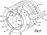
- An indicator member 40 can extend from a portion of the transmission assembly 16 and can be disposed over an external scale 42 ( FIG. 4 ).
- the indicator member 40 by pointing to portions of the external scale 42, can be shown to indicate to a user a relatively precise value of torque at the output spindle 24.
- the user can manually rotate the housing 12 of the power tool 10, with the motor 34 deactivated, to drive a fastener to a desired torque level.
- the torque level can be indicated by the indicator member 40 on the external scale 42.
- the user can drive a fastener to a desired torque level that can be indicated by the indicator member 40 on the external scale 42, while the user continues to drive the fastener with the motor 34 activated, in contrast to manually rotating the housing 12.
- the housing 12 can include an end cap assembly 50 and a pair of mating shells 52, 54.
- the housing 12 can define a motor cavity 56 and a transmission cavity 58.
- the motor assembly 14 can be housed in the motor cavity 56 and can include a rotatable output shaft 60 that can extend from the motor 34 and through a motor housing 62 to engage (and form a portion of) the transmission assembly 16.
- the transmission assembly 16 can be housed in the transmission cavity 58 and can include a speed selector mechanism 70.
- the transmission assembly 16 can include a plurality of reduction elements or reduction gearsets that can be selectively engaged (and disengaged) by the speed selector mechanism 70 to provide a plurality of user-selectable speed ratios.
- the output from the transmission assembly 16 can be transmitted to the output spindle assembly 20 ( FIG. 2 ).
- the chuck 26 ( FIG. 2 ) can be incorporated in or coupled for rotation with the output spindle assembly 20 to permit torque to be transmitted to, for example, a tool bit (not shown).
- the clutch mechanism 18 can be included with the transmission assembly 16 and can be operable for limiting the magnitude of the torque associated with the drive input to a predetermined and selectable torque limit.
- the transmission assembly 16 can be a three-stage, three-speed transmission that can include a transmission sleeve 80, a reduction gearset assembly 82 and the speed selector mechanism 70.
- the reduction gearset assembly 82 can include a first reduction gear set 84, a second reduction gear set 86 and a third reduction gear set 88. While each of the first, second and third reduction gear sets 84, 86, 88 can be planetary gear sets, it will be appreciated in light of the disclosure that various other types of reduction gear sets can be substituted for one or more of the reduction gear sets forming the reduction gear set assembly 82 such as a parallel shaft spur gear style transmission.
- the first reduction gear set 84 can include a first ring gear 90 and a first set of planet gears 92 that can connect to a first planet carrier 94.
- a clutch face 96 can be formed on a front face of the first ring gear 90.
- the second reduction gear set 86 can include a second sun gear 98, a second ring gear 100 and a second set of planet gears 102 that can connect to a second planet carrier 104.
- the output shaft 60 of the motor 34 can serve as a sun gear for the first reduction gearset 84.
- the third reduction gear set 88 can include a third sun gear 110, a third ring gear 112, a third set of planet gears 114 connected to a third planet carrier 116.
- the third sun gear 110 can be fixed for rotation with the second planet carrier 104.
- Annular clip grooves 120 can be formed in the outer periphery of the second and third ring gear 100, 112.
- the clip grooves 120 can hold a portion of a wire clip 122.
- the wire clip 122 can connect to the speed selector mechanism 70 to move the ring gears 100, 112 to establish the speed ratios of the transmission assembly 16. While the speeds of the transmission assembly 16 can be adjusted with the speed selector mechanism 70, the magnitude of the clutch torque can be dictated by an adjustment mechanism 130 ( FIG. 2 ). Positioning of the adjustment mechanism 130 at certain predetermined positions, can push a pin member 132 and can contact the clutch face 96.
- the clutch face 96 can operate to inhibit rotation of the first ring gear 90 relative to the transmission sleeve 80 when the magnitude of the clutch torque is at a first, value.
- the first ring gear 90 can overcome the force of the pin member 132 on the clutch face 96 to permit the first ring gear 90 to rotate relative to the transmission sleeve 80. Additional details about the multi-speed transmission assembly 16 and the clutch mechanism 18 are disclosed in commonly assigned U.S. Patent Application Entitled “Housing and Gearbox for Drill or Driver” filed on June 14, 2006, and assigned Application Serial No. 11/453,315 .
- the power tool 10 can include a spindle lock assembly 150.
- the spindle lock assembly 150 can include an anvil 152, a plurality of roller elements 154 between projections 156 that can extend from a face 158 of a transmission component 160.
- the transmission component 160 can be the third planet carrier 116.
- the spindle lock assembly 150 can operate, in some aspects, similar to what is referred to as a sprag clutch. Additional details of a sprag clutch or automatic shaft lock are disclosed in commonly assigned U.S. Patent No. 5,984,022 issued November 16, 1999 .
- the spindle lock assembly 150 can be in a drive condition when, typically, the power tool 10 is used to insert a fastener, etc.
- the spindle lock assembly 150 can "free wheel” and thus not interrupt rotational power through the spindle lock assembly 150.
- the spindle lock assembly 150 can bind (i.e., move to a lock condition) and therefore, inhibit rotational power through the spindle lock assembly 150.
- the lock condition for example, the user can impart a force on the chuck 26 to secure a tool bit in the chuck 26. In doing so, the spindle lock assembly 150 can move into the lock condition to resist the force used to secure the tool bit in the chuck 26.
- the force imparted on the chuck 26 and/or the output spindle 24 can be transmitted to an outer ring member 162.
- an outer ring of the spindle lock can be secured to a housing against rotation.
- the outer ring member 162 is able to rotate within the housing 12.
- the outer ring member 162 can further include an indentation 164 that can hold a portion of a spring 166.
- the outer ring member 162 is connected to the housing 12 via the spring 166 so that the force transmitted to
- the outer ring member 162 can compress the spring 166 between the outer ring member 162 and the housing 12.
- one end 168 of the spring 166 is held in the indentation 164 in the outer ring member 162 of the spindle lock assembly 150.
- An end 170 of the spring 166 (i.e., the other end) is secured to an interior portion 172 of the housing 12.
- the spring 166 is able to compress when a force in a rotation direction that causes the spindle lock assembly 150 to move into the lock condition is applied to the output spindle 24.
- the spring 166 can contained between the outer ring member 162 and the housing 12 in a compressed state regardless of the position of the outer ring member 162 relative to the housing 12.
- the spring 166 can be used in lieu of (or in addition to) one or more compliant members such as, but not limited to, suitable elastic material. Moreover, the spring 166 (or other suitable compliant member) can be arranged so that the movement of the outer ring member 162 can elongate the spring rather than compressing it.
- the rotational force can be applied to the spindle lock assembly 150 when, for example, the user rotates the housing 12 of the power tool 10 ( FIG. 1 ) to manually tighten the fastener or coupling. In this example, the user does not activate the motor 34.
- the outer ring member 162 will move and compress the spring 166 based on the load applied to the output spindle 24.
- the spring 166 can be configured and calibrated so that as the movement of the outer ring member 162 can be indicative of the torque applied to the output spindle 24.
- the indicator member 40 that can extend from the outer ring member 162 can be used to point to portions of the external scale 42. By pointing to portions of the external scale 42, a specific value of the torque at the output spindle 24 can be communicated to the user, while the user is rotating the housing 12.
- the external scale can provide tick marks and values indicative of a range of inch-pounds of torque applied to the output spindle 24.
- the spring 166 is a wrap spring that has multiple coils 174 disposed around a portion of the transmission assembly 16.
- the wrap spring can be configured to encircle a portion of the transmission assembly 16.
- the wrap spring can also be configured to be disposed between the spindle lock assembly 150 and the transmission assembly 16.
- the housing 12 can be larger in a radial direction to accommodate the wrap spring.
- the housing 12 can be larger in an axial direction to accommodate the wrap spring.
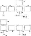
- a motor 200 can drive a transmission 202.
- a spindle lock assembly 204 can connect an output spindle 206 to the transmission 202.
- the spindle lock assembly 204 is also shown with a spring 208 that can connect a portion of the spindle lock assembly 204 to a portion of the housing 210.
- the motor 200 and/or the transmission 202 can be directly connected to the housing 210 and thus cannot rotate relative to the housing 210.
- the portion of the spindle lock assembly 204 connected to the spring 208 can move to compress the spring 208, when a force is applied to the output spindle 206.
- the portion of the spindle lock assembly 204 can move to compress the spring 208.
- the movement of the portion of the spindle lock assembly 204 and the spring 208 can be calibrated to indicate by a torque indicator 212 a value of torque at the output spindle 206.
- the manual rotation of the power tool to further drive the fastener or tighten the coupling is done while the motor 200 is not activated.
- a motor 250 can drive a transmission 252.
- a spindle lock assembly 254 can connect an output spindle 256 to the transmission 252.
- a spring 258 can connect the motor 250 and/or the transmission 252 to the housing 260 allowing the motor 250 and/or the transmission 252 to move relative to the housing 260.
- the motor 250 and/or the transmission 252 can move to compress the spring 258, when a force is applied to the output spindle 256.
- the motor 250 and/or the transmission 252 can move within the housing 260 to compress the spring 258.
- the movement of the motor 250 and/or the transmission 252 and the spring 258 can be calibrated to indicate by a torque indicator 262 a value of torque at the output spindle 206.
- the torque indicator 262 indicates a value of torque at the output spindle 256 while the motor 250 is activated to provide a real-time indication of the value of torque at the output spindle 256.
- an exemplary method of using the power tool 10 in accordance with the present teachings includes, at 300, selecting a clutch setting with the adjustment mechanism 130 on the power tool 10.
- the user can drive the fastener or coupling until the power tool 10 clutches out. By clutching out, the clutch opens and rotational power from the motor 34 is reduced to (or removed from) the output spindle 24.
- the user can manually rotate the housing 12 of the power tool 10 to continue to drive the fastener or tighten the coupling against the spindle lock assembly being in the locked condition, while the motor is deactivated.
- the user can stop rotating the tool housing when the indicator member 40 indicates the desired torque level on the external scale 42.
Claims (8)
- Outil électrique comprenant :un boîtier (12) ;un ensemble moteur (14) connecté à un ensemble de transmission (16), dans lequel ledit ensemble moteur (14) et ledit ensemble de transmission (16) sont fixés à l'encontre d'une rotation dans le boîtier (12) ;une pluralité de saillies (156) qui s'étend d'un composant (160) dudit ensemble de transmission (16) ;un fuseau de sortie (24) ;un ensemble de verrouillage de fuseau (150) qui raccorde ledit fuseau de sortie (24) audit ensemble de transmission (16), ledit ensemble de verrouillage de fuseau (150) qui comprend une enclume (152), un élément annulaire extérieur (162) et une pluralité d'éléments de galets (154), dans lequel lesdits éléments de galets (154) et lesdites saillies (156) sont disposées entre ladite enclume (152) et ledit élément annulaire extérieur (162) ;caractérisé en ce qu'un élément indicateur (40) est raccordé audit élément annulaire extérieur (162) ; ledit élément indicateur (40) ayant une partie qui est disposée à l'extérieur dudit boîtier ;un élément de ressort (166) qui raccorde ledit élément annulaire extérieur (162) à une partie interne (172) dudit boîtier (12) ;une échelle (42) établie sur une partie extérieure dudit boîtier (12), dans lequel ladite partie dudit élément indicateur (40) est disposée par-dessus ladite échelle (42) et ladite partie dudit élément indicateur (40) se déplace par rapport à ladite échelle (42) pour indiquer une valeur de couple sur ledit fuseau de sortie (24).
- Outil électrique selon la revendication 1, dans lequel ledit élément de ressort (166) est un élément de ressort avec des spires successives qui s'enroulent autour d'une partie de l'ensemble de transmission (16).
- Outil électrique selon la revendication 1, dans lequel ledit élément de ressort (166) est un élément de ressort avec des spires successives qui sont disposées entre ledit ensemble de transmission (16) et ledit fuseau de sortie (24).
- Outil électrique selon la revendication 1, dans lequel ledit composant (160) dudit ensemble de transmission (16) à partir duquel ladite pluralité de saillies (156) s'étend comprend un porte-satellite d'une transmission planétaire.
- Outil électrique selon la revendication 1, dans lequel ledit élément de ressort (166) est un élément de ressort, dans lequel ledit élément de ressort est à l'état comprimé quelle que soit une position angulaire dudit élément annulaire extérieur (162).
- Procédé comprenant :la rotation d'un boîtier (12) d'un outil électrique pour faire tourner un fuseau de sortie (24) de l'outil électrique ;le déplacement d'un ensemble de verrouillage de fuseau (150) dans un état de verrouillage ;caractérisé en ce que le procédé comprend en outre les étapes consistant à :comprimer un élément de ressort (166) entre ledit ensemble de verrouillage de fuseau (150) et ledit boîtier (12) ;déplacer un élément indicateur (40) raccordé à l'ensemble de verrouillage de fuseau (150) par rapport au boîtier (12) ;indiquer la valeur du couple appliqué à ledit fuseau de sortie (24) sur une échelle externe (42) du boîtier (12) avec une partie de l'élément indicateur (40) qui s'étend sur le boîtier (12) sur lequel l'échelle externe (42) est établie.
- Procédé selon la revendication 6, dans lequel la compression de l'élément de ressort (166) entre l'ensemble de verrouillage de fuseau (150) et le boîtier (12) comprend le déplacement d'un élément annulaire extérieur (62) sur une distance qui est proportionnelle au couple appliqué au fuseau de sortie (24).
- Procédé selon la revendication 6, comprenant en outre le prolongement de la rotation du boîtier (12) de l'outil électrique pour augmenter les couples appliqués au fuseau de sortie (24) de l'outil électrique, dans lequel ladite partie de l'élément indicateur (40) se déplace par rapport à l'échelle externe (42) établie sur le boîtier (12) pour refléter l'augmentation du couple appliqué au fuseau de sortie (24).
Applications Claiming Priority (3)
| Application Number | Priority Date | Filing Date | Title |
|---|---|---|---|
| US82533906P | 2006-09-12 | 2006-09-12 | |
| US11/853,600 US7578357B2 (en) | 2006-09-12 | 2007-09-11 | Driver with external torque value indicator integrated with spindle lock and related method |
| PCT/US2007/019765 WO2008033366A2 (fr) | 2006-09-12 | 2007-09-12 | Organe d'entraînement avec indicateur de valeur de couple externe intégré à un verrouillage de broche et procédé apparenté |
Publications (3)
| Publication Number | Publication Date |
|---|---|
| EP2073953A2 EP2073953A2 (fr) | 2009-07-01 |
| EP2073953A4 EP2073953A4 (fr) | 2017-10-04 |
| EP2073953B1 true EP2073953B1 (fr) | 2019-06-26 |
Family
ID=39184313
Family Applications (3)
| Application Number | Title | Priority Date | Filing Date |
|---|---|---|---|
| EP11177219.0A Withdrawn EP2397259A3 (fr) | 2006-09-12 | 2007-09-12 | Capteur de couple optique |
| EP07811753.8A Not-in-force EP2073953B1 (fr) | 2006-09-12 | 2007-09-12 | Organe d'entraînement avec indicateur de valeur de couple externe intégré à un verrouillage de broche et procédé apparenté |
| EP07838072.2A Not-in-force EP2076748B1 (fr) | 2006-09-12 | 2007-09-12 | Capteur de couple optique |
Family Applications Before (1)
| Application Number | Title | Priority Date | Filing Date |
|---|---|---|---|
| EP11177219.0A Withdrawn EP2397259A3 (fr) | 2006-09-12 | 2007-09-12 | Capteur de couple optique |
Family Applications After (1)
| Application Number | Title | Priority Date | Filing Date |
|---|---|---|---|
| EP07838072.2A Not-in-force EP2076748B1 (fr) | 2006-09-12 | 2007-09-12 | Capteur de couple optique |
Country Status (4)
| Country | Link |
|---|---|
| US (2) | US7578357B2 (fr) |
| EP (3) | EP2397259A3 (fr) |
| CN (1) | CN201419340Y (fr) |
| WO (1) | WO2008033386A2 (fr) |
Families Citing this family (47)
| Publication number | Priority date | Publication date | Assignee | Title |
|---|---|---|---|---|
| JP4754395B2 (ja) * | 2006-04-20 | 2011-08-24 | 株式会社マキタ | ねじ締め機 |
| US7578357B2 (en) * | 2006-09-12 | 2009-08-25 | Black & Decker Inc. | Driver with external torque value indicator integrated with spindle lock and related method |
| US8732896B2 (en) | 2006-10-17 | 2014-05-27 | Mtd Products Inc | Hybrid electric cleaning device |
| WO2008048618A2 (fr) | 2006-10-17 | 2008-04-24 | Desa Ip. Llc | Dispositif électrique hybride |
| US8076873B1 (en) * | 2007-06-01 | 2011-12-13 | Mtd Products Inc | Hybrid outdoor power equipment |
| US20100096152A1 (en) * | 2008-10-16 | 2010-04-22 | Top Gearbox Industry Co., Ltd. | Lever type output shaft locking device |
| US9016398B2 (en) * | 2008-12-04 | 2015-04-28 | Ingersoll-Rand Company | Disc-shaped torque transducer |
| DE102009027442A1 (de) * | 2009-07-03 | 2011-01-05 | Robert Bosch Gmbh | Handwerkzeugmaschine |
| US8205510B2 (en) * | 2009-10-27 | 2012-06-26 | Diluigi And Associates, Llc | Hand brake torque input coupler and indicator |
| US9174328B2 (en) * | 2010-03-08 | 2015-11-03 | Techtronic Power Tools Technology Limited | Power tool having a spindle lock |
| US8584770B2 (en) | 2010-03-23 | 2013-11-19 | Black & Decker Inc. | Spindle bearing arrangement for a power tool |
| US8529567B2 (en) | 2010-06-03 | 2013-09-10 | Biomet Microfixation, Llc | Surgical device with smart bit recognition collet assembly to set a desired application mode |
| US20110303432A1 (en) * | 2010-06-14 | 2011-12-15 | Stauffer Joseph G | Power tool transmission |
| US8393231B2 (en) * | 2010-11-15 | 2013-03-12 | Legend Lifestyle Products Corp. | Multifunctional torque tool detection device |
| EP2707177B1 (fr) * | 2011-05-13 | 2019-01-09 | ABAS Inc. | Outil portatif à moteur pré-réglable |
| CN102814792B (zh) * | 2011-06-09 | 2014-12-17 | 苏州宝时得电动工具有限公司 | 动力工具及应用于该动力工具的工作头和转接器 |
| US8801569B2 (en) | 2011-12-14 | 2014-08-12 | Massachusetts Institute Of Technology | Methods and apparatus for flexure-based torque sensor in a bicycle |
| US8704904B2 (en) | 2011-12-23 | 2014-04-22 | H4 Engineering, Inc. | Portable system for high quality video recording |
| US9908182B2 (en) | 2012-01-30 | 2018-03-06 | Black & Decker Inc. | Remote programming of a power tool |
| WO2013116810A1 (fr) | 2012-02-03 | 2013-08-08 | H4 Engineering, Inc. | Appareil et procédé de sécurisation d'un dispositif électronique portable |
| US8749634B2 (en) | 2012-03-01 | 2014-06-10 | H4 Engineering, Inc. | Apparatus and method for automatic video recording |
| JP2015513858A (ja) | 2012-03-02 | 2015-05-14 | エイチ4 エンジニアリング, インコーポレイテッドH4 Engineering, Inc. | 多機能自動ビデオ記録装置 |
| US9723192B1 (en) | 2012-03-02 | 2017-08-01 | H4 Engineering, Inc. | Application dependent video recording device architecture |
| JP5895159B2 (ja) * | 2012-03-13 | 2016-03-30 | パナソニックIpマネジメント株式会社 | 動力工具 |
| US9193055B2 (en) | 2012-04-13 | 2015-11-24 | Black & Decker Inc. | Electronic clutch for power tool |
| US8919456B2 (en) | 2012-06-08 | 2014-12-30 | Black & Decker Inc. | Fastener setting algorithm for drill driver |
| AU2013286547B2 (en) | 2012-07-06 | 2017-03-09 | H4 Engineering, Inc. | A remotely controlled automatic camera tracking system |
| EP2720018A1 (fr) | 2012-10-15 | 2014-04-16 | Continental Automotive GmbH | Mesure de couple de torsion pour arbres rotatifs |
| CN104070490B (zh) * | 2013-03-29 | 2016-11-23 | 南京德朔实业有限公司 | 电动工具 |
| US9395257B2 (en) * | 2013-05-10 | 2016-07-19 | Snap-On Incorporated | Electronic torque tool with integrated real-time clock |
| DE102013209173A1 (de) * | 2013-05-17 | 2014-11-20 | Robert Bosch Gmbh | Handwerkzeugmaschine mit einer Spindellockvorrichtung |
| US9265551B2 (en) | 2013-07-19 | 2016-02-23 | Pro-Dex, Inc. | Torque-limiting screwdrivers |
| DE102014226325A1 (de) * | 2014-12-17 | 2016-06-23 | Sirona Dental Systems Gmbh | Zahnärztliches Instrument mit einem Getriebe zum Antrieb eines Werkzeugs |
| DE102014019547B3 (de) * | 2014-12-23 | 2016-05-12 | Samson Ag | Drehmoment- und Winkelsensor und Stellantrieb |
| WO2016196979A1 (fr) | 2015-06-05 | 2016-12-08 | Ingersoll-Rand Company | Outils de percussion avec fonctionnalités d'alignement de couronne dentée |
| US11491616B2 (en) * | 2015-06-05 | 2022-11-08 | Ingersoll-Rand Industrial U.S., Inc. | Power tools with user-selectable operational modes |
| US10615670B2 (en) | 2015-06-05 | 2020-04-07 | Ingersoll-Rand Industrial U.S., Inc. | Power tool user interfaces |
| WO2016196899A1 (fr) | 2015-06-05 | 2016-12-08 | Ingersoll-Rand Company | Boîtiers d'outil électrique |
| CN109475375B (zh) | 2016-06-07 | 2022-02-15 | 普罗德克斯有限公司 | 扭矩限制螺丝刀装置、系统和方法 |
| US11453105B2 (en) | 2016-09-13 | 2022-09-27 | Milwaukee Electric Tool Corporation | Powered ratcheting torque wrench |
| US10625405B2 (en) | 2016-09-13 | 2020-04-21 | Milwaukee Electric Tool Corporation | Powered ratcheting torque wrench |
| JP6592190B2 (ja) * | 2016-11-10 | 2019-10-16 | 日東工器株式会社 | 電動工具並びにその制御装置及び制御回路 |
| EP3840918B1 (fr) | 2018-08-20 | 2024-03-13 | Pro-Dex, Inc. | Dispositifs de limitation de couple |
| GB201904786D0 (en) * | 2019-04-04 | 2019-05-22 | Norbar Torque Tools | Torque application tool |
| US11919117B2 (en) | 2020-02-17 | 2024-03-05 | Milwaukee Electric Tool Corporation | Electronic spindle lock for a power tool |
| US11691259B2 (en) * | 2020-05-18 | 2023-07-04 | Techtronic Cordless Gp | Rotary tool |
| CN113059216B (zh) * | 2021-04-02 | 2023-05-09 | 浙江时中电器有限公司 | 一种防屑环保型电钻 |
Family Cites Families (73)
| Publication number | Priority date | Publication date | Assignee | Title |
|---|---|---|---|---|
| US3783682A (en) * | 1971-12-16 | 1974-01-08 | Bell Telephone Labor Inc | Torque testing screwdriver with automatic torque indicating means |
| SU386289A1 (ru) * | 1972-02-01 | 1973-06-14 | Устройство для определения крутящего момента валов сельскохозяйственных агрегатов | |
| US4019363A (en) * | 1973-10-09 | 1977-04-26 | Masoneilan International, Inc. | Calibration apparatus and method |
| US4249435A (en) * | 1979-07-30 | 1981-02-10 | Smith William J | Workpiece turning hand tool with torque control |
| US4540318A (en) * | 1982-07-29 | 1985-09-10 | Robert Bosch, Gmbh | Rotary electrical tool with speed control, especially drill |
| US4471280A (en) | 1983-05-06 | 1984-09-11 | The Bendix Corporation | Anti-log power amplifier for reversible D.C. motor in automotive steering controls |
| GB2148493A (en) * | 1983-09-12 | 1985-05-30 | Crane Electronics | Torque transducing attachments for air-driven impact tools |
| US4558601A (en) * | 1984-01-06 | 1985-12-17 | J. S. Technology, Inc. | Digital indicating torque wrench |
| ES8605898A1 (es) * | 1985-03-14 | 1986-03-16 | Bendiberica Sa | Perfeccionamientos en dispositivos captadores de par para mecanismo de accionamiento, especialmente de timoneria o ruedas orientables de un vehiculo |
| JPS62157523A (ja) * | 1985-12-28 | 1987-07-13 | Aisin Warner Ltd | 光式ロ−タリエンコ−ダ |
| US4845998A (en) * | 1988-02-01 | 1989-07-11 | Kent-Moore Corporation | Apparatus for precision tensioning of threaded fasteners |
| US5025903A (en) * | 1990-01-09 | 1991-06-25 | Black & Decker Inc. | Dual mode rotary power tool with adjustable output torque |
| US5686672A (en) | 1990-12-10 | 1997-11-11 | Klauber; Robert D. | Stress and load variation detector |
| DE4039794A1 (de) * | 1990-12-13 | 1992-06-17 | Forst Saltus Werk | Drehmomentschluessel |
| DE59200150D1 (de) * | 1991-02-19 | 1994-06-09 | Horst Glonner | Auswertungseinrichtung für eine auf einer drehbaren welle erfasste messgrösse. |
| US5335557A (en) | 1991-11-26 | 1994-08-09 | Taizo Yasutake | Touch sensitive input control device |
| US6597347B1 (en) | 1991-11-26 | 2003-07-22 | Itu Research Inc. | Methods and apparatus for providing touch-sensitive input in multiple degrees of freedom |
| GB9202868D0 (en) | 1992-02-12 | 1992-03-25 | Lucas Ind Plc | Optical torque sensors and steering systems for vehicles incorporating them |
| US5490430A (en) | 1992-05-14 | 1996-02-13 | Anderson; Philip M. | Optical torque sensor utilizing change in reflectance grating line spacing |
| US5389780A (en) | 1992-05-14 | 1995-02-14 | Anderson; Philip M. | Optical torque sensor utilizing single polarizing area filters and mechanical amplifier |
| JP3098358B2 (ja) * | 1992-11-27 | 2000-10-16 | 三菱電機株式会社 | 位置検出素子、その位置検出素子を用いた位置検出方法、および光学式ロータリーエンコーダ |
| DE4307131C2 (de) * | 1993-03-06 | 1995-11-16 | Albert Kipfelsberger | Kraftschrauber mit elektronischer Drehmomentbegrenzung |
| JPH06293265A (ja) | 1993-04-07 | 1994-10-21 | Rhythm Corp | 電動パワーステアリング装置 |
| US5426986A (en) | 1993-07-15 | 1995-06-27 | Northern Research & Engineering Corporation | Absorption dynamometer torque measuring device and calibration method |
| GB9316841D0 (en) | 1993-08-13 | 1993-09-29 | Lucas Ind Plc | Optical torque sensor incorporating sensor failure diagnostics |
| GB9316851D0 (en) | 1993-08-13 | 1993-09-29 | Lucas Ind Plc | Enhanced position signals in optical torque sensors |
| GB9316842D0 (en) | 1993-08-13 | 1993-09-29 | Lucas Ind Plc | Improved optical torque sensor |
| US5535867A (en) * | 1993-11-01 | 1996-07-16 | Coccaro; Albert V. | Torque regulating coupling |
| GB9400511D0 (en) | 1994-01-12 | 1994-03-09 | Lucas Ind Plc | Optical torque sensors |
| US5451127A (en) * | 1994-04-12 | 1995-09-19 | Chung; Lee-Hsin-Chih | Dual-function electrical hand drill |
| KR100378576B1 (ko) * | 1994-08-25 | 2004-04-03 | 티알더블유 루카스베리티 일렉트릭 스티어링 리미티드 | 변위센서및토크센서 |
| DE19708058A1 (de) | 1997-02-28 | 1998-09-03 | Bock Orthopaed Ind | Muskelbetriebenes Radfahrzeug |
| US5788021A (en) * | 1997-06-05 | 1998-08-04 | Tsai; Feng Chun | Automatic outputshaft locking mechanism for electric tools |
| FR2774470B1 (fr) * | 1998-02-04 | 2000-03-03 | Roulements Soc Nouvelle | Capteur de couple et colonne de direction pourvue d'un tel capteur |
| JP2000002603A (ja) * | 1998-06-17 | 2000-01-07 | Koyo Seiko Co Ltd | トルクセンサ |
| US5984022A (en) * | 1998-07-09 | 1999-11-16 | Black & Decker Inc. | Automatic shaft lock |
| US6095020A (en) * | 1999-01-11 | 2000-08-01 | Beere Precision Medical Instruments, Inc. | Hand tool having a variable torque-limiting in-line drive |
| BR0004031A (pt) * | 1999-02-11 | 2000-11-21 | Trw Inc | Processos para controlar um servo motor elétrico, e para controlar um sistema de direção assistida elétrico tendo um motor de ca a magneto permanente, aparelho para controlar um motor elétrico de ca tendo uma pluralidade de fases, sistema de direção assistida elétrico, e, processo para controlar um sistema de direção assistida elétrico tendo um servo motor elétrico a magneto permanente |
| US6037735A (en) * | 1999-03-01 | 2000-03-14 | Eastman Kodak Company | Slow-speed servomechanism |
| US6536536B1 (en) * | 1999-04-29 | 2003-03-25 | Stephen F. Gass | Power tools |
| US6587211B1 (en) | 1999-07-28 | 2003-07-01 | Creo Srl | Interferometric torque and power sensor |
| DE29914341U1 (de) * | 1999-08-16 | 1999-10-07 | Chung Lee Hsin Chih | Drehknopf-Schalteinrichtung |
| US6729812B2 (en) * | 1999-12-06 | 2004-05-04 | Theodore G. Yaksich | Power driver having geared tool holder |
| US20020035876A1 (en) * | 2000-03-08 | 2002-03-28 | Donaldson Robert D. | Torque process control method and apparatus for fluid powered tools |
| CA2339430A1 (fr) * | 2000-03-10 | 2001-09-10 | Black & Decker Inc. | Marteau |
| US6268790B1 (en) | 2000-03-24 | 2001-07-31 | Trw Inc. | Anti-theft method and apparatus |
| US6311787B1 (en) * | 2000-04-18 | 2001-11-06 | Black & Decker Inc. | Power driven rotary device |
| US6520274B1 (en) | 2000-04-25 | 2003-02-18 | Visteon Global Technologies, Inc. | Modular electric steering gear assembly |
| US6431289B1 (en) * | 2001-01-23 | 2002-08-13 | Black & Decker Inc. | Multi-speed power tool transmission |
| US6676557B2 (en) * | 2001-01-23 | 2004-01-13 | Black & Decker Inc. | First stage clutch |
| US6502648B2 (en) * | 2001-01-23 | 2003-01-07 | Black & Decker Inc. | 360 degree clutch collar |
| US6805207B2 (en) * | 2001-01-23 | 2004-10-19 | Black & Decker Inc. | Housing with functional overmold |
| US7101300B2 (en) * | 2001-01-23 | 2006-09-05 | Black & Decker Inc. | Multispeed power tool transmission |
| US6460649B2 (en) * | 2001-02-16 | 2002-10-08 | Delphi Technologies, Inc. | Passive starting of a torque-ripple-free electric power steering system |
| JP2002254336A (ja) * | 2001-03-02 | 2002-09-10 | Hitachi Koki Co Ltd | 電動工具 |
| US6702090B2 (en) * | 2001-03-14 | 2004-03-09 | Milwaukee Electric Tool Corporation | Power tool and spindle lock system |
| US6547053B2 (en) * | 2001-03-30 | 2003-04-15 | Zf Meritor, Llc | Torsional vibration damper |
| US6817528B2 (en) | 2001-07-17 | 2004-11-16 | Honeywell International Inc. | Reflective apparatus and method for optically sensing relative torque employing Moirè fringes |
| US7222862B2 (en) * | 2001-10-26 | 2007-05-29 | Black & Decker Inc. | Tool holder |
| US6915710B2 (en) * | 2001-11-06 | 2005-07-12 | Delphi Technology, Inc. | Method and apparatus for correcting attenuation in an optical torque sensor |
| US7063201B2 (en) * | 2001-11-27 | 2006-06-20 | Milwaukee Electric Tool Corporation | Power tool and spindle lock system |
| US6948381B1 (en) | 2002-04-09 | 2005-09-27 | Rockwell Automation Technologies, Inc. | System and method for sensing torque on a rotating shaft |
| US7395871B2 (en) * | 2003-04-24 | 2008-07-08 | Black & Decker Inc. | Method for detecting a bit jam condition using a freely rotatable inertial mass |
| US6926095B2 (en) * | 2003-08-11 | 2005-08-09 | Power Network Industry Co., Ltd. | Power tool transmission device |
| JP4227028B2 (ja) * | 2004-01-09 | 2009-02-18 | 株式会社マキタ | ドライバドリル |
| JP4405900B2 (ja) * | 2004-03-10 | 2010-01-27 | 株式会社マキタ | インパクトドライバ |
| JP3899086B2 (ja) * | 2004-05-11 | 2007-03-28 | ミネベア株式会社 | 回転体トルク測定装置 |
| EP1792039A4 (fr) * | 2004-08-11 | 2010-09-15 | William Szieff | Outil dote d'indicateurs de mouvement et d'orientation |
| US7308948B2 (en) * | 2004-10-28 | 2007-12-18 | Makita Corporation | Electric power tool |
| US7377331B2 (en) * | 2005-04-06 | 2008-05-27 | Power Network Industry Co., Ltd. | Damping driving axle |
| US7588398B2 (en) * | 2005-04-19 | 2009-09-15 | Black & Decker Inc. | Tool chuck with power take off and dead spindle features |
| JP4754395B2 (ja) * | 2006-04-20 | 2011-08-24 | 株式会社マキタ | ねじ締め機 |
| US7578357B2 (en) * | 2006-09-12 | 2009-08-25 | Black & Decker Inc. | Driver with external torque value indicator integrated with spindle lock and related method |
-
2007
- 2007-09-11 US US11/853,600 patent/US7578357B2/en not_active Expired - Fee Related
- 2007-09-12 US US11/854,110 patent/US7591195B2/en not_active Expired - Fee Related
- 2007-09-12 WO PCT/US2007/019794 patent/WO2008033386A2/fr active Application Filing
- 2007-09-12 CN CN2007900000895U patent/CN201419340Y/zh not_active Expired - Fee Related
- 2007-09-12 EP EP11177219.0A patent/EP2397259A3/fr not_active Withdrawn
- 2007-09-12 EP EP07811753.8A patent/EP2073953B1/fr not_active Not-in-force
- 2007-09-12 EP EP07838072.2A patent/EP2076748B1/fr not_active Not-in-force
Non-Patent Citations (1)
| Title |
|---|
| None * |
Also Published As
| Publication number | Publication date |
|---|---|
| CN201419340Y (zh) | 2010-03-10 |
| EP2076748A2 (fr) | 2009-07-08 |
| EP2397259A2 (fr) | 2011-12-21 |
| EP2073953A4 (fr) | 2017-10-04 |
| US20080060487A1 (en) | 2008-03-13 |
| EP2397259A3 (fr) | 2017-12-27 |
| EP2073953A2 (fr) | 2009-07-01 |
| US20080060451A1 (en) | 2008-03-13 |
| WO2008033386A2 (fr) | 2008-03-20 |
| US7578357B2 (en) | 2009-08-25 |
| EP2076748B1 (fr) | 2013-08-28 |
| EP2076748A4 (fr) | 2010-10-27 |
| US7591195B2 (en) | 2009-09-22 |
| WO2008033386A3 (fr) | 2008-07-03 |
Similar Documents
| Publication | Publication Date | Title |
|---|---|---|
| EP2073953B1 (fr) | Organe d'entraînement avec indicateur de valeur de couple externe intégré à un verrouillage de broche et procédé apparenté | |
| US11738439B2 (en) | Power tool with planetary transmission | |
| US7066691B2 (en) | Power drill/driver | |
| US8251158B2 (en) | Multi-speed power tool transmission with alternative ring gear configuration | |
| EP2635410B1 (fr) | Outil à chocs avec embrayage réglable | |
| EP2644324B1 (fr) | Boîtier et boîte de vitesse pour foreuse ou visseuse | |
| EP2533943B1 (fr) | Appareil de serrage d'organes de fixation filetés | |
| US8887831B2 (en) | Transmission for power tool with variable speed ratio | |
| US20140274548A1 (en) | Clutch for power tool | |
| EP2614931A1 (fr) | Outil électrique avec couple d'embrayage | |
| EP2554336A2 (fr) | Outil pourvu d'un ensemble de verrouillage de la broche contrôlé par couple | |
| US10513023B2 (en) | Power tool | |
| WO2008033366A2 (fr) | Organe d'entraînement avec indicateur de valeur de couple externe intégré à un verrouillage de broche et procédé apparenté | |
| EP1468208B1 (fr) | Entrainement d'une perceuse electrique | |
| JP3129070U (ja) | ボルト・ナット締付装置 | |
| US20070158091A1 (en) | Power hand tool having power transmission clutch | |
| JPS5949873B2 (ja) | 電動ドライバ− | |
| GB2414051A (en) | Power tool clutch plate having perpendicularly extending leg members | |
| GB2387628A (en) | Power drill | |
| JP2003236767A (ja) | 作動機構、作動機構アタッチメント、及び作動工具 |
Legal Events
| Date | Code | Title | Description |
|---|---|---|---|
| PUAI | Public reference made under article 153(3) epc to a published international application that has entered the european phase |
Free format text: ORIGINAL CODE: 0009012 |
|
| 17P | Request for examination filed |
Effective date: 20090408 |
|
| AK | Designated contracting states |
Kind code of ref document: A2 Designated state(s): AT BE BG CH CY CZ DE DK EE ES FI FR GB GR HU IE IS IT LI LT LU LV MC MT NL PL PT RO SE SI SK TR |
|
| AX | Request for extension of the european patent |
Extension state: AL BA HR MK RS |
|
| DAX | Request for extension of the european patent (deleted) | ||
| REG | Reference to a national code |
Ref country code: DE Ref legal event code: R079 Ref document number: 602007058697 Country of ref document: DE Free format text: PREVIOUS MAIN CLASS: B23Q0017100000 Ipc: G01L0003000000 |
|
| A4 | Supplementary search report drawn up and despatched |
Effective date: 20170906 |
|
| RIC1 | Information provided on ipc code assigned before grant |
Ipc: B25B 23/147 20060101ALI20170831BHEP Ipc: B25B 23/145 20060101ALI20170831BHEP Ipc: G01L 3/12 20060101ALI20170831BHEP Ipc: G01L 3/00 20060101AFI20170831BHEP |
|
| STAA | Information on the status of an ep patent application or granted ep patent |
Free format text: STATUS: REQUEST FOR EXAMINATION WAS MADE |
|
| GRAP | Despatch of communication of intention to grant a patent |
Free format text: ORIGINAL CODE: EPIDOSNIGR1 |
|
| STAA | Information on the status of an ep patent application or granted ep patent |
Free format text: STATUS: GRANT OF PATENT IS INTENDED |
|
| INTG | Intention to grant announced |
Effective date: 20190415 |
|
| GRAS | Grant fee paid |
Free format text: ORIGINAL CODE: EPIDOSNIGR3 |
|
| GRAA | (expected) grant |
Free format text: ORIGINAL CODE: 0009210 |
|
| STAA | Information on the status of an ep patent application or granted ep patent |
Free format text: STATUS: THE PATENT HAS BEEN GRANTED |
|
| AK | Designated contracting states |
Kind code of ref document: B1 Designated state(s): AT BE BG CH CY CZ DE DK EE ES FI FR GB GR HU IE IS IT LI LT LU LV MC MT NL PL PT RO SE SI SK TR |
|
| REG | Reference to a national code |
Ref country code: GB Ref legal event code: FG4D |
|
| REG | Reference to a national code |
Ref country code: CH Ref legal event code: EP |
|
| REG | Reference to a national code |
Ref country code: AT Ref legal event code: REF Ref document number: 1148837 Country of ref document: AT Kind code of ref document: T Effective date: 20190715 |
|
| REG | Reference to a national code |
Ref country code: DE Ref legal event code: R096 Ref document number: 602007058697 Country of ref document: DE |
|
| REG | Reference to a national code |
Ref country code: IE Ref legal event code: FG4D |
|
| REG | Reference to a national code |
Ref country code: NL Ref legal event code: MP Effective date: 20190626 |
|
| PG25 | Lapsed in a contracting state [announced via postgrant information from national office to epo] |
Ref country code: SE Free format text: LAPSE BECAUSE OF FAILURE TO SUBMIT A TRANSLATION OF THE DESCRIPTION OR TO PAY THE FEE WITHIN THE PRESCRIBED TIME-LIMIT Effective date: 20190626 Ref country code: FI Free format text: LAPSE BECAUSE OF FAILURE TO SUBMIT A TRANSLATION OF THE DESCRIPTION OR TO PAY THE FEE WITHIN THE PRESCRIBED TIME-LIMIT Effective date: 20190626 Ref country code: LT Free format text: LAPSE BECAUSE OF FAILURE TO SUBMIT A TRANSLATION OF THE DESCRIPTION OR TO PAY THE FEE WITHIN THE PRESCRIBED TIME-LIMIT Effective date: 20190626 |
|
| REG | Reference to a national code |
Ref country code: LT Ref legal event code: MG4D |
|
| PG25 | Lapsed in a contracting state [announced via postgrant information from national office to epo] |
Ref country code: BG Free format text: LAPSE BECAUSE OF FAILURE TO SUBMIT A TRANSLATION OF THE DESCRIPTION OR TO PAY THE FEE WITHIN THE PRESCRIBED TIME-LIMIT Effective date: 20190926 Ref country code: GR Free format text: LAPSE BECAUSE OF FAILURE TO SUBMIT A TRANSLATION OF THE DESCRIPTION OR TO PAY THE FEE WITHIN THE PRESCRIBED TIME-LIMIT Effective date: 20190927 Ref country code: LV Free format text: LAPSE BECAUSE OF FAILURE TO SUBMIT A TRANSLATION OF THE DESCRIPTION OR TO PAY THE FEE WITHIN THE PRESCRIBED TIME-LIMIT Effective date: 20190626 |
|
| PGFP | Annual fee paid to national office [announced via postgrant information from national office to epo] |
Ref country code: GB Payment date: 20190912 Year of fee payment: 13 |
|
| REG | Reference to a national code |
Ref country code: AT Ref legal event code: MK05 Ref document number: 1148837 Country of ref document: AT Kind code of ref document: T Effective date: 20190626 |
|
| PG25 | Lapsed in a contracting state [announced via postgrant information from national office to epo] |
Ref country code: NL Free format text: LAPSE BECAUSE OF FAILURE TO SUBMIT A TRANSLATION OF THE DESCRIPTION OR TO PAY THE FEE WITHIN THE PRESCRIBED TIME-LIMIT Effective date: 20190626 Ref country code: EE Free format text: LAPSE BECAUSE OF FAILURE TO SUBMIT A TRANSLATION OF THE DESCRIPTION OR TO PAY THE FEE WITHIN THE PRESCRIBED TIME-LIMIT Effective date: 20190626 Ref country code: AT Free format text: LAPSE BECAUSE OF FAILURE TO SUBMIT A TRANSLATION OF THE DESCRIPTION OR TO PAY THE FEE WITHIN THE PRESCRIBED TIME-LIMIT Effective date: 20190626 Ref country code: CZ Free format text: LAPSE BECAUSE OF FAILURE TO SUBMIT A TRANSLATION OF THE DESCRIPTION OR TO PAY THE FEE WITHIN THE PRESCRIBED TIME-LIMIT Effective date: 20190626 Ref country code: RO Free format text: LAPSE BECAUSE OF FAILURE TO SUBMIT A TRANSLATION OF THE DESCRIPTION OR TO PAY THE FEE WITHIN THE PRESCRIBED TIME-LIMIT Effective date: 20190626 Ref country code: SK Free format text: LAPSE BECAUSE OF FAILURE TO SUBMIT A TRANSLATION OF THE DESCRIPTION OR TO PAY THE FEE WITHIN THE PRESCRIBED TIME-LIMIT Effective date: 20190626 Ref country code: PT Free format text: LAPSE BECAUSE OF FAILURE TO SUBMIT A TRANSLATION OF THE DESCRIPTION OR TO PAY THE FEE WITHIN THE PRESCRIBED TIME-LIMIT Effective date: 20191028 |
|
| PG25 | Lapsed in a contracting state [announced via postgrant information from national office to epo] |
Ref country code: IS Free format text: LAPSE BECAUSE OF FAILURE TO SUBMIT A TRANSLATION OF THE DESCRIPTION OR TO PAY THE FEE WITHIN THE PRESCRIBED TIME-LIMIT Effective date: 20191026 Ref country code: IT Free format text: LAPSE BECAUSE OF FAILURE TO SUBMIT A TRANSLATION OF THE DESCRIPTION OR TO PAY THE FEE WITHIN THE PRESCRIBED TIME-LIMIT Effective date: 20190626 Ref country code: ES Free format text: LAPSE BECAUSE OF FAILURE TO SUBMIT A TRANSLATION OF THE DESCRIPTION OR TO PAY THE FEE WITHIN THE PRESCRIBED TIME-LIMIT Effective date: 20190626 |
|
| PG25 | Lapsed in a contracting state [announced via postgrant information from national office to epo] |
Ref country code: TR Free format text: LAPSE BECAUSE OF FAILURE TO SUBMIT A TRANSLATION OF THE DESCRIPTION OR TO PAY THE FEE WITHIN THE PRESCRIBED TIME-LIMIT Effective date: 20190626 |
|
| PG25 | Lapsed in a contracting state [announced via postgrant information from national office to epo] |
Ref country code: DK Free format text: LAPSE BECAUSE OF FAILURE TO SUBMIT A TRANSLATION OF THE DESCRIPTION OR TO PAY THE FEE WITHIN THE PRESCRIBED TIME-LIMIT Effective date: 20190626 Ref country code: PL Free format text: LAPSE BECAUSE OF FAILURE TO SUBMIT A TRANSLATION OF THE DESCRIPTION OR TO PAY THE FEE WITHIN THE PRESCRIBED TIME-LIMIT Effective date: 20190626 |
|
| PG25 | Lapsed in a contracting state [announced via postgrant information from national office to epo] |
Ref country code: IS Free format text: LAPSE BECAUSE OF FAILURE TO SUBMIT A TRANSLATION OF THE DESCRIPTION OR TO PAY THE FEE WITHIN THE PRESCRIBED TIME-LIMIT Effective date: 20200224 Ref country code: MC Free format text: LAPSE BECAUSE OF FAILURE TO SUBMIT A TRANSLATION OF THE DESCRIPTION OR TO PAY THE FEE WITHIN THE PRESCRIBED TIME-LIMIT Effective date: 20190626 |
|
| REG | Reference to a national code |
Ref country code: CH Ref legal event code: PL |
|
| REG | Reference to a national code |
Ref country code: DE Ref legal event code: R097 Ref document number: 602007058697 Country of ref document: DE |
|
| PLBE | No opposition filed within time limit |
Free format text: ORIGINAL CODE: 0009261 |
|
| STAA | Information on the status of an ep patent application or granted ep patent |
Free format text: STATUS: NO OPPOSITION FILED WITHIN TIME LIMIT |
|
| PG2D | Information on lapse in contracting state deleted |
Ref country code: IS |
|
| PG25 | Lapsed in a contracting state [announced via postgrant information from national office to epo] |
Ref country code: CH Free format text: LAPSE BECAUSE OF NON-PAYMENT OF DUE FEES Effective date: 20190930 Ref country code: IE Free format text: LAPSE BECAUSE OF NON-PAYMENT OF DUE FEES Effective date: 20190912 Ref country code: LI Free format text: LAPSE BECAUSE OF NON-PAYMENT OF DUE FEES Effective date: 20190930 Ref country code: LU Free format text: LAPSE BECAUSE OF NON-PAYMENT OF DUE FEES Effective date: 20190912 |
|
| 26N | No opposition filed |
Effective date: 20200603 |
|
| REG | Reference to a national code |
Ref country code: BE Ref legal event code: MM Effective date: 20190930 |
|
| PG25 | Lapsed in a contracting state [announced via postgrant information from national office to epo] |
Ref country code: SI Free format text: LAPSE BECAUSE OF FAILURE TO SUBMIT A TRANSLATION OF THE DESCRIPTION OR TO PAY THE FEE WITHIN THE PRESCRIBED TIME-LIMIT Effective date: 20190626 Ref country code: BE Free format text: LAPSE BECAUSE OF NON-PAYMENT OF DUE FEES Effective date: 20190930 |
|
| PG25 | Lapsed in a contracting state [announced via postgrant information from national office to epo] |
Ref country code: FR Free format text: LAPSE BECAUSE OF NON-PAYMENT OF DUE FEES Effective date: 20190930 |
|
| PGFP | Annual fee paid to national office [announced via postgrant information from national office to epo] |
Ref country code: DE Payment date: 20200901 Year of fee payment: 14 |
|
| GBPC | Gb: european patent ceased through non-payment of renewal fee |
Effective date: 20200912 |
|
| PG25 | Lapsed in a contracting state [announced via postgrant information from national office to epo] |
Ref country code: CY Free format text: LAPSE BECAUSE OF FAILURE TO SUBMIT A TRANSLATION OF THE DESCRIPTION OR TO PAY THE FEE WITHIN THE PRESCRIBED TIME-LIMIT Effective date: 20190626 |
|
| PG25 | Lapsed in a contracting state [announced via postgrant information from national office to epo] |
Ref country code: MT Free format text: LAPSE BECAUSE OF FAILURE TO SUBMIT A TRANSLATION OF THE DESCRIPTION OR TO PAY THE FEE WITHIN THE PRESCRIBED TIME-LIMIT Effective date: 20190626 Ref country code: HU Free format text: LAPSE BECAUSE OF FAILURE TO SUBMIT A TRANSLATION OF THE DESCRIPTION OR TO PAY THE FEE WITHIN THE PRESCRIBED TIME-LIMIT; INVALID AB INITIO Effective date: 20070912 |
|
| PG25 | Lapsed in a contracting state [announced via postgrant information from national office to epo] |
Ref country code: GB Free format text: LAPSE BECAUSE OF NON-PAYMENT OF DUE FEES Effective date: 20200912 |
|
| REG | Reference to a national code |
Ref country code: DE Ref legal event code: R119 Ref document number: 602007058697 Country of ref document: DE |
|
| PG25 | Lapsed in a contracting state [announced via postgrant information from national office to epo] |
Ref country code: DE Free format text: LAPSE BECAUSE OF NON-PAYMENT OF DUE FEES Effective date: 20220401 |