EP2073871B1 - An injection device with electronic detecting means - Google Patents
An injection device with electronic detecting means Download PDFInfo
- Publication number
- EP2073871B1 EP2073871B1 EP07820718A EP07820718A EP2073871B1 EP 2073871 B1 EP2073871 B1 EP 2073871B1 EP 07820718 A EP07820718 A EP 07820718A EP 07820718 A EP07820718 A EP 07820718A EP 2073871 B1 EP2073871 B1 EP 2073871B1
- Authority
- EP
- European Patent Office
- Prior art keywords
- dose
- injection device
- amount
- spring
- injection
- Prior art date
- Legal status (The legal status is an assumption and is not a legal conclusion. Google has not performed a legal analysis and makes no representation as to the accuracy of the status listed.)
- Active
Links
- 238000002347 injection Methods 0.000 title claims description 232
- 239000007924 injection Substances 0.000 title claims description 232
- 230000007246 mechanism Effects 0.000 claims description 39
- 238000006073 displacement reaction Methods 0.000 claims description 21
- 239000003814 drug Substances 0.000 claims description 14
- 229940079593 drug Drugs 0.000 claims description 13
- 230000004044 response Effects 0.000 claims description 6
- 238000001514 detection method Methods 0.000 description 16
- 239000003990 capacitor Substances 0.000 description 9
- 239000002184 metal Substances 0.000 description 4
- 230000008901 benefit Effects 0.000 description 2
- 230000006835 compression Effects 0.000 description 2
- 238000007906 compression Methods 0.000 description 2
- NOESYZHRGYRDHS-UHFFFAOYSA-N insulin Chemical compound N1C(=O)C(NC(=O)C(CCC(N)=O)NC(=O)C(CCC(O)=O)NC(=O)C(C(C)C)NC(=O)C(NC(=O)CN)C(C)CC)CSSCC(C(NC(CO)C(=O)NC(CC(C)C)C(=O)NC(CC=2C=CC(O)=CC=2)C(=O)NC(CCC(N)=O)C(=O)NC(CC(C)C)C(=O)NC(CCC(O)=O)C(=O)NC(CC(N)=O)C(=O)NC(CC=2C=CC(O)=CC=2)C(=O)NC(CSSCC(NC(=O)C(C(C)C)NC(=O)C(CC(C)C)NC(=O)C(CC=2C=CC(O)=CC=2)NC(=O)C(CC(C)C)NC(=O)C(C)NC(=O)C(CCC(O)=O)NC(=O)C(C(C)C)NC(=O)C(CC(C)C)NC(=O)C(CC=2NC=NC=2)NC(=O)C(CO)NC(=O)CNC2=O)C(=O)NCC(=O)NC(CCC(O)=O)C(=O)NC(CCCNC(N)=N)C(=O)NCC(=O)NC(CC=3C=CC=CC=3)C(=O)NC(CC=3C=CC=CC=3)C(=O)NC(CC=3C=CC(O)=CC=3)C(=O)NC(C(C)O)C(=O)N3C(CCC3)C(=O)NC(CCCCN)C(=O)NC(C)C(O)=O)C(=O)NC(CC(N)=O)C(O)=O)=O)NC(=O)C(C(C)CC)NC(=O)C(CO)NC(=O)C(C(C)O)NC(=O)C1CSSCC2NC(=O)C(CC(C)C)NC(=O)C(NC(=O)C(CCC(N)=O)NC(=O)C(CC(N)=O)NC(=O)C(NC(=O)C(N)CC=1C=CC=CC=1)C(C)C)CC1=CN=CN1 NOESYZHRGYRDHS-UHFFFAOYSA-N 0.000 description 2
- 238000012544 monitoring process Methods 0.000 description 2
- 102000018997 Growth Hormone Human genes 0.000 description 1
- 108010051696 Growth Hormone Proteins 0.000 description 1
- 102000004877 Insulin Human genes 0.000 description 1
- 108090001061 Insulin Proteins 0.000 description 1
- 239000011248 coating agent Substances 0.000 description 1
- 238000000576 coating method Methods 0.000 description 1
- 206010012601 diabetes mellitus Diseases 0.000 description 1
- 239000000122 growth hormone Substances 0.000 description 1
- 239000000383 hazardous chemical Substances 0.000 description 1
- 231100000206 health hazard Toxicity 0.000 description 1
- 230000001771 impaired effect Effects 0.000 description 1
- 229940125396 insulin Drugs 0.000 description 1
- 238000005457 optimization Methods 0.000 description 1
- 230000005019 pattern of movement Effects 0.000 description 1
- 230000003252 repetitive effect Effects 0.000 description 1
- 230000000007 visual effect Effects 0.000 description 1
Images





Classifications
-
- A—HUMAN NECESSITIES
- A61—MEDICAL OR VETERINARY SCIENCE; HYGIENE
- A61M—DEVICES FOR INTRODUCING MEDIA INTO, OR ONTO, THE BODY; DEVICES FOR TRANSDUCING BODY MEDIA OR FOR TAKING MEDIA FROM THE BODY; DEVICES FOR PRODUCING OR ENDING SLEEP OR STUPOR
- A61M5/00—Devices for bringing media into the body in a subcutaneous, intra-vascular or intramuscular way; Accessories therefor, e.g. filling or cleaning devices, arm-rests
- A61M5/178—Syringes
- A61M5/20—Automatic syringes, e.g. with automatically actuated piston rod, with automatic needle injection, filling automatically
-
- A—HUMAN NECESSITIES
- A61—MEDICAL OR VETERINARY SCIENCE; HYGIENE
- A61M—DEVICES FOR INTRODUCING MEDIA INTO, OR ONTO, THE BODY; DEVICES FOR TRANSDUCING BODY MEDIA OR FOR TAKING MEDIA FROM THE BODY; DEVICES FOR PRODUCING OR ENDING SLEEP OR STUPOR
- A61M5/00—Devices for bringing media into the body in a subcutaneous, intra-vascular or intramuscular way; Accessories therefor, e.g. filling or cleaning devices, arm-rests
- A61M5/178—Syringes
- A61M5/31—Details
- A61M5/315—Pistons; Piston-rods; Guiding, blocking or restricting the movement of the rod or piston; Appliances on the rod for facilitating dosing ; Dosing mechanisms
- A61M5/31533—Dosing mechanisms, i.e. setting a dose
- A61M5/31545—Setting modes for dosing
- A61M5/31548—Mechanically operated dose setting member
- A61M5/3155—Mechanically operated dose setting member by rotational movement of dose setting member, e.g. during setting or filling of a syringe
- A61M5/31553—Mechanically operated dose setting member by rotational movement of dose setting member, e.g. during setting or filling of a syringe without axial movement of dose setting member
-
- A—HUMAN NECESSITIES
- A61—MEDICAL OR VETERINARY SCIENCE; HYGIENE
- A61M—DEVICES FOR INTRODUCING MEDIA INTO, OR ONTO, THE BODY; DEVICES FOR TRANSDUCING BODY MEDIA OR FOR TAKING MEDIA FROM THE BODY; DEVICES FOR PRODUCING OR ENDING SLEEP OR STUPOR
- A61M5/00—Devices for bringing media into the body in a subcutaneous, intra-vascular or intramuscular way; Accessories therefor, e.g. filling or cleaning devices, arm-rests
- A61M5/178—Syringes
- A61M5/31—Details
- A61M5/315—Pistons; Piston-rods; Guiding, blocking or restricting the movement of the rod or piston; Appliances on the rod for facilitating dosing ; Dosing mechanisms
- A61M5/31533—Dosing mechanisms, i.e. setting a dose
- A61M5/31545—Setting modes for dosing
- A61M5/31548—Mechanically operated dose setting member
- A61M5/31556—Accuracy improving means
-
- A—HUMAN NECESSITIES
- A61—MEDICAL OR VETERINARY SCIENCE; HYGIENE
- A61M—DEVICES FOR INTRODUCING MEDIA INTO, OR ONTO, THE BODY; DEVICES FOR TRANSDUCING BODY MEDIA OR FOR TAKING MEDIA FROM THE BODY; DEVICES FOR PRODUCING OR ENDING SLEEP OR STUPOR
- A61M5/00—Devices for bringing media into the body in a subcutaneous, intra-vascular or intramuscular way; Accessories therefor, e.g. filling or cleaning devices, arm-rests
- A61M5/178—Syringes
- A61M5/31—Details
- A61M5/315—Pistons; Piston-rods; Guiding, blocking or restricting the movement of the rod or piston; Appliances on the rod for facilitating dosing ; Dosing mechanisms
- A61M5/31565—Administration mechanisms, i.e. constructional features, modes of administering a dose
- A61M5/31576—Constructional features or modes of drive mechanisms for piston rods
- A61M5/31583—Constructional features or modes of drive mechanisms for piston rods based on rotational translation, i.e. movement of piston rod is caused by relative rotation between the user activated actuator and the piston rod
-
- G—PHYSICS
- G01—MEASURING; TESTING
- G01D—MEASURING NOT SPECIALLY ADAPTED FOR A SPECIFIC VARIABLE; ARRANGEMENTS FOR MEASURING TWO OR MORE VARIABLES NOT COVERED IN A SINGLE OTHER SUBCLASS; TARIFF METERING APPARATUS; MEASURING OR TESTING NOT OTHERWISE PROVIDED FOR
- G01D5/00—Mechanical means for transferring the output of a sensing member; Means for converting the output of a sensing member to another variable where the form or nature of the sensing member does not constrain the means for converting; Transducers not specially adapted for a specific variable
- G01D5/12—Mechanical means for transferring the output of a sensing member; Means for converting the output of a sensing member to another variable where the form or nature of the sensing member does not constrain the means for converting; Transducers not specially adapted for a specific variable using electric or magnetic means
- G01D5/14—Mechanical means for transferring the output of a sensing member; Means for converting the output of a sensing member to another variable where the form or nature of the sensing member does not constrain the means for converting; Transducers not specially adapted for a specific variable using electric or magnetic means influencing the magnitude of a current or voltage
- G01D5/24—Mechanical means for transferring the output of a sensing member; Means for converting the output of a sensing member to another variable where the form or nature of the sensing member does not constrain the means for converting; Transducers not specially adapted for a specific variable using electric or magnetic means influencing the magnitude of a current or voltage by varying capacitance
- G01D5/241—Mechanical means for transferring the output of a sensing member; Means for converting the output of a sensing member to another variable where the form or nature of the sensing member does not constrain the means for converting; Transducers not specially adapted for a specific variable using electric or magnetic means influencing the magnitude of a current or voltage by varying capacitance by relative movement of capacitor electrodes
- G01D5/2412—Mechanical means for transferring the output of a sensing member; Means for converting the output of a sensing member to another variable where the form or nature of the sensing member does not constrain the means for converting; Transducers not specially adapted for a specific variable using electric or magnetic means influencing the magnitude of a current or voltage by varying capacitance by relative movement of capacitor electrodes by varying overlap
-
- A—HUMAN NECESSITIES
- A61—MEDICAL OR VETERINARY SCIENCE; HYGIENE
- A61M—DEVICES FOR INTRODUCING MEDIA INTO, OR ONTO, THE BODY; DEVICES FOR TRANSDUCING BODY MEDIA OR FOR TAKING MEDIA FROM THE BODY; DEVICES FOR PRODUCING OR ENDING SLEEP OR STUPOR
- A61M5/00—Devices for bringing media into the body in a subcutaneous, intra-vascular or intramuscular way; Accessories therefor, e.g. filling or cleaning devices, arm-rests
- A61M5/178—Syringes
- A61M5/20—Automatic syringes, e.g. with automatically actuated piston rod, with automatic needle injection, filling automatically
- A61M2005/2006—Having specific accessories
- A61M2005/202—Having specific accessories cocking means, e.g. to bias the main drive spring of an injector
-
- A—HUMAN NECESSITIES
- A61—MEDICAL OR VETERINARY SCIENCE; HYGIENE
- A61M—DEVICES FOR INTRODUCING MEDIA INTO, OR ONTO, THE BODY; DEVICES FOR TRANSDUCING BODY MEDIA OR FOR TAKING MEDIA FROM THE BODY; DEVICES FOR PRODUCING OR ENDING SLEEP OR STUPOR
- A61M5/00—Devices for bringing media into the body in a subcutaneous, intra-vascular or intramuscular way; Accessories therefor, e.g. filling or cleaning devices, arm-rests
- A61M5/178—Syringes
- A61M5/31—Details
- A61M2005/3125—Details specific display means, e.g. to indicate dose setting
-
- A—HUMAN NECESSITIES
- A61—MEDICAL OR VETERINARY SCIENCE; HYGIENE
- A61M—DEVICES FOR INTRODUCING MEDIA INTO, OR ONTO, THE BODY; DEVICES FOR TRANSDUCING BODY MEDIA OR FOR TAKING MEDIA FROM THE BODY; DEVICES FOR PRODUCING OR ENDING SLEEP OR STUPOR
- A61M2205/00—General characteristics of the apparatus
- A61M2205/58—Means for facilitating use, e.g. by people with impaired vision
- A61M2205/581—Means for facilitating use, e.g. by people with impaired vision by audible feedback
-
- A—HUMAN NECESSITIES
- A61—MEDICAL OR VETERINARY SCIENCE; HYGIENE
- A61M—DEVICES FOR INTRODUCING MEDIA INTO, OR ONTO, THE BODY; DEVICES FOR TRANSDUCING BODY MEDIA OR FOR TAKING MEDIA FROM THE BODY; DEVICES FOR PRODUCING OR ENDING SLEEP OR STUPOR
- A61M2205/00—General characteristics of the apparatus
- A61M2205/58—Means for facilitating use, e.g. by people with impaired vision
- A61M2205/582—Means for facilitating use, e.g. by people with impaired vision by tactile feedback
-
- A—HUMAN NECESSITIES
- A61—MEDICAL OR VETERINARY SCIENCE; HYGIENE
- A61M—DEVICES FOR INTRODUCING MEDIA INTO, OR ONTO, THE BODY; DEVICES FOR TRANSDUCING BODY MEDIA OR FOR TAKING MEDIA FROM THE BODY; DEVICES FOR PRODUCING OR ENDING SLEEP OR STUPOR
- A61M2205/00—General characteristics of the apparatus
- A61M2205/58—Means for facilitating use, e.g. by people with impaired vision
- A61M2205/583—Means for facilitating use, e.g. by people with impaired vision by visual feedback
-
- A—HUMAN NECESSITIES
- A61—MEDICAL OR VETERINARY SCIENCE; HYGIENE
- A61M—DEVICES FOR INTRODUCING MEDIA INTO, OR ONTO, THE BODY; DEVICES FOR TRANSDUCING BODY MEDIA OR FOR TAKING MEDIA FROM THE BODY; DEVICES FOR PRODUCING OR ENDING SLEEP OR STUPOR
- A61M5/00—Devices for bringing media into the body in a subcutaneous, intra-vascular or intramuscular way; Accessories therefor, e.g. filling or cleaning devices, arm-rests
- A61M5/178—Syringes
- A61M5/31—Details
- A61M5/315—Pistons; Piston-rods; Guiding, blocking or restricting the movement of the rod or piston; Appliances on the rod for facilitating dosing ; Dosing mechanisms
- A61M5/31533—Dosing mechanisms, i.e. setting a dose
- A61M5/31545—Setting modes for dosing
- A61M5/31548—Mechanically operated dose setting member
- A61M5/3156—Mechanically operated dose setting member using volume steps only adjustable in discrete intervals, i.e. individually distinct intervals
-
- A—HUMAN NECESSITIES
- A61—MEDICAL OR VETERINARY SCIENCE; HYGIENE
- A61M—DEVICES FOR INTRODUCING MEDIA INTO, OR ONTO, THE BODY; DEVICES FOR TRANSDUCING BODY MEDIA OR FOR TAKING MEDIA FROM THE BODY; DEVICES FOR PRODUCING OR ENDING SLEEP OR STUPOR
- A61M5/00—Devices for bringing media into the body in a subcutaneous, intra-vascular or intramuscular way; Accessories therefor, e.g. filling or cleaning devices, arm-rests
- A61M5/178—Syringes
- A61M5/31—Details
- A61M5/315—Pistons; Piston-rods; Guiding, blocking or restricting the movement of the rod or piston; Appliances on the rod for facilitating dosing ; Dosing mechanisms
- A61M5/31533—Dosing mechanisms, i.e. setting a dose
- A61M5/31545—Setting modes for dosing
- A61M5/31548—Mechanically operated dose setting member
- A61M5/31563—Mechanically operated dose setting member interacting with a displaceable stop member
-
- A—HUMAN NECESSITIES
- A61—MEDICAL OR VETERINARY SCIENCE; HYGIENE
- A61M—DEVICES FOR INTRODUCING MEDIA INTO, OR ONTO, THE BODY; DEVICES FOR TRANSDUCING BODY MEDIA OR FOR TAKING MEDIA FROM THE BODY; DEVICES FOR PRODUCING OR ENDING SLEEP OR STUPOR
- A61M5/00—Devices for bringing media into the body in a subcutaneous, intra-vascular or intramuscular way; Accessories therefor, e.g. filling or cleaning devices, arm-rests
- A61M5/178—Syringes
- A61M5/31—Details
- A61M5/315—Pistons; Piston-rods; Guiding, blocking or restricting the movement of the rod or piston; Appliances on the rod for facilitating dosing ; Dosing mechanisms
- A61M5/31565—Administration mechanisms, i.e. constructional features, modes of administering a dose
- A61M5/31566—Means improving security or handling thereof
- A61M5/3157—Means providing feedback signals when administration is completed
Definitions
- the present invention relates to an injection device having a dose setting mechanism, the operation of which causes energy to be stored in a spring member, i.e. a so-called 'auto injection device'. More particularly, the present invention relates to an injection device as described above, and comprising electronic detection means for detecting the amount of a set dose and/or the amount of an injected dose.
- Various injection devices have been described, which comprise energy storing means, such as a spring member, in which energy is stored during dose setting. Subsequently, during injection of a previously set dose, energy stored in the energy storing means is released and used for driving an amount of drug corresponding to the previously set dose out of the injection device.
- energy storing means such as a spring member
- injection devices examples include WO 2006/045528 and in WO 2006/045529 .
- the injection devices disclosed in WO 2006/045528 and in WO 2006/034429 both comprise mechanical means, in the form of a dose indicator barrel, for detecting and displaying the amount of a set dose.
- the dose indicator barrel returns to its initial position, and it is thereby also capable of indicating the amount of an injected dose.
- an injection device for injecting a dose of drug and having a dose setting mechanism, an injection mechanism and means for electronically detecting the amount of a set dose is known from US 5 320 609 A .
- an electronic display at an exterior part of the housing of the injection device for displaying various relevant parameters, such as set dose, injected dose, time lapsed since last dose was injected, kind of medicament contained in the device, etc.
- an object of the invention to provide an injection device comprising energy storing means as described above, and in which the accuracy of detecting the amount of a set dose and/or the amount of an injected dose is improved as compared to similar prior art injection devices.
- an injection device for injecting a dose of drug comprising:
- the injection device according to the present invention is particularly suitable for repetitive self injections, such as injections of growth hormone, or of insulin for treatment of diabetes, because the injection device can be operated in an easy and intuitive manner, and it is therefore not necessary that the person operating the injection device is a medical staff member or similar.
- the injection device may advantageously have an elongated shape, i.e. the injection device may be a 'pen-like' injection device.
- the dose setting mechanism is operable to set a desired dose.
- the dose setting mechanism is a mechanism which the user operates when he or she wishes to set a dose to be injected.
- the dose setting mechanism may be rotationally operable, i.e. it may comprise a member which the user must rotate in order to set a dose, e.g. in the form of a dose knob.
- the dose setting mechanism may be substantially linearly operable. In this case the dose setting mechanism comprises a member which the user must pull or push in a substantially linear movement in order to set a desired dose.
- Operation of the dose setting member causes energy to be stored in a spring member.
- This may, e.g., be achieved by compressing a compressible spring member, by tensioning a torsion spring, or in any other suitable manner.
- the spring member is capable of storing energy during dose setting and of releasing the stored energy during injection of a set dose.
- the stored energy causes the set dose to be injected, i.e. it is not necessary for the user to apply further force or movement to the injection device during injection in order to cause a set dose to be injected.
- This is an advantage because it ensures a very uniform delivery of the drug. It is also possible for the user to keep the injection device more still during injection because it is not necessary to move the fingers in order to cause the dose to be injected.
- the injection device comprises means for electronically detecting the amount of a set dose and/or means for electronically detecting the amount of an injected dose.
- the injection device is capable of keeping track of the amount of a set dose, the amount of an injected dose, or the amount of a set dose as well as the amount of an injected dose.
- the detection is performed electronically rather than mechanically, such as by means of a helically moving scale drum. As a consequence, the detection may be performed very accurately.
- the injection device since there is no requirement of the presence of a scale drum or other similar mechanical means for detecting the amount of a set dose and/or the amount of an injected dose, the injection device can be designed without consideration to the presence, accessibility and/or visibility of such mechanical means.
- the injection device may be designed in a manner which provides optimization with regard to other parameters, such as size, shape, user friendliness, etc. This is very advantageous.
- the electronic display means may be or comprise an LCD display, an OLED display, an ELD display, a bi-stable e-ink display, or any other suitable kind of display.
- Using an electronic display reduces the risk that a user misreads a displayed number indicating a set or an injected dose. This is very advantageous, since a misreading may lead to an incorrect dose being injected, and an incorrect dose may have severe consequences to the person receiving the incorrect dose.
- the means for electronically detecting the amount of a set dose and/or the means for electronically detecting the amount of an injected dose may be adapted to detect an angular displacement between at least two members, said angular displacement being indicative of the amount of a set dose and/or the amount of an injected dose.
- one of the members may be rotationally movable during dose setting and/or during injection, while another member remains substantially fixed, e.g. relatively to a housing of the injection device, during the same operation.
- at least two members may each be rotationally movable, e.g. relatively to a housing of the injection device, either in such a manner that they rotate in the same direction at different angular velocities, or in such a manner that they rotate in opposite directions.
- the movement of the members must result in a relative angular displacement, and the angular displacement must be indicative of the amount of a set dose and/or the amount of an injected dose.
- the means for electronically detecting the amount of a set dose and/or the means for electronically detecting the amount of an injected dose may comprise at least two substantially disc shaped members being arranged with a substantially fixed mutual distance along a longitudinal direction of the injection device, said substantially disc shaped members being rotationally movable relatively to each other during dose setting and/or injection, and an angular displacement between said substantially disc shaped members may in this case be indicative of the amount of a set dose and/or the amount of an injected dose.
- the relative movement between the disc shaped members is purely rotational, i.e. the mutual distance along the longitudinal direction is substantially fixed.
- the members may, alternatively, have any other suitable shape other than disc shaped.
- the mutual distance between the at least two members may be variable during dose setting and/or during injection of a dose.
- the amount(s) may be detected by means of a relative linear displacement between two members.
- the members may be linearly movable. It is also conceivable to provide an injection device in which the amount of a set dose is detected by means of a relative rotational displacement, and the amount of an injected dose is detected by means of a relative linear displacement, or vice versa.
- the means for electronically detecting the amount of a set dose and/or the means for electronically detecting the amount of an injected dose may be adapted to detect the amount of a set dose and/or the amount of an injected dose by measuring a capacitance.
- This may advantageously be obtained by providing a set of disc shaped members with a metal coating, thereby forming a set of electrodes when the disc shaped members are positioned opposite each other, and thereby forming a capacitor.
- the metal By applying the metal to the disc shaped members in a pattern which varies angularly, the area of the resulting capacitor will vary as a function of relative angular displacement between the disc shaped members.
- the means for electronically detecting the amount of a set dose and/or the means for electronically detecting the amount of an injected dose may be adapted to detect the amount(s) in any other suitable manner, such as optically or inductively, e.g. using quadrature detection. Detection using mechanical switches is also possible.
- the injection device may comprise means for electronically detecting the amount of a set dose, as well as means for electronically detecting the amount of an injected dose, and the means for electronically detecting the amount of an injected dose may form part of the means for electronically detecting the amount of a set dose.
- the same detection means is used for detecting the amount of a set dose as well as the amount of an injected dose. This may, e.g., be obtained using a single set of disc shaped members, as described above, being rotationally movable relatively to each other during dose setting as well as during injection of a set dose.
- the means for electronically detecting the amount of a set dose and the means for electronically detecting the amount of an injected dose may be separate, e.g.
- one set of disc shaped members will be rotationally movable relatively to each other during dose setting, and the other set of disc shaped members will be rotationally movable relatively to each other during injection of a set dose.
- the injection device may comprise means for electronically detecting the amount of a set dose only, and the amount of an injected dose may either not be detected or be detected mechanically.
- the injection device may comprise means for detecting the amount of an injected dose only, and the amount of a set dose may be detected mechanically, e.g. using an ordinary scale drum.
- the injection device may further comprise a release member for releasing energy stored in the spring member, thereby causing a set dose to be injected.
- the release member may, e.g., be or comprise a button which the user may press when the desired dose has been set and the injection device has been arranged in such a manner that a dose can be delivered at a selected and suitable injection site.
- the release member may advantageously be operatively connected to locking means which can maintain the spring member in an energy storing position, e.g. a tensed position, and the operation of the release member should, in this case, cause the locking means to be moved into a position in which it allows the stored energy to be released.
- the spring member is also arranged to store some amount of energy when no dose is set, i.e. the spring member is preferably pre-tensed to a certain degree. This is in order to ensure that the entire amount of a set dose is actually injected when the injection mechanism is operated.
- the spring member may be or comprise a torsion spring.
- the spring member may be or comprise a compressible spring, a leaf spring, or any other suitable kind of spring being capable of storing and releasing energy.
- An embodiment comprising a compressible spring will be described in further detail below.
- the injection device may further comprise a nut positioned in an interior part of the injection device, said nut being movable during dose setting and during injection between a first position along a longitudinal direction of the injection device, said first position corresponding to a maximum settable dose, and a second position along the longitudinal direction of the injection device, said second position corresponding to complete injection of a previously set dose.
- the nut ensures that it is not possible to set a dose which exceeds a maximum dose.
- the maximum settable dose may, e.g., be chosen so as to ensure that it is safe for the user to inject a set dose, e.g. so as to ensure that there will not be health hazards involved with injecting a set dose.
- the nut provides an 'end-of-dose' feature, i.e. when the nut is in the second position, the entire dose has been injected, and this may even be communicated to the user, e.g. in a visual, audible and/or tactile manner.
- the spring member may be or comprise a compressible spring, and the compressible spring may extend essentially along the length of the injection device.
- the injection device preferably has an elongated shape, i.e. the injection device is preferably of a pen-like type.
- the direction in which the injection device is elongated defines an axial direction
- the dimension of the injection device along this axial direction defines a length of the injection device.
- the compressible spring may extend essentially along this length, i.e. between a proximal end of the injection device and a distal end of the injection device. Accordingly, the compressible spring is relatively long. Thereby it is possible to store a sufficient amount of energy in the spring.
- the compressible spring may be arranged coaxially and surrounding one or more other longitudinal parts of the injection device, e.g. a dose rod and/or a piston rod.
- the spring member may comprise two or more compressible springs.
- the spring members may be positioned 'side-by-side', e.g. in parallel with a dose rod and/or a piston rod, thereby providing the possibility of designing the injection device with a relatively flat appearance without reducing the amount of energy it is possible to store in the spring member.
- the injection device may further comprise a spring compressing member being movable along a longitudinal direction of the injection device during dose setting and during injection, said spring compressing member being positioned in abutment with the compressible spring, and the spring compressing member may be operatively connected to the dose setting mechanism in such a manner that when the dose setting mechanism is operated the spring compressing member is caused to perform a movement along the longitudinal direction of the injection device, thereby compressing the compressible spring.
- the spring compressing member when the dose setting mechanism is operated, the spring compressing member is moved in such a manner that it causes compression of the compressible spring. Thereby energy is stored in the compressible spring.
- the spring compressing member should be allowed to move in an opposite direction, thereby allowing the energy stored in the compressible spring during dose setting to be released. According to one embodiment this may be obtained in the following manner.
- the spring compressing member is connected to another member via a thread connection. Rotating a dose knob in order to set a dose causes rotation of the spring compressing member, and due to the thread connection, the spring compressing member additionally moves in an axial direction, thereby causing compression of the compressible spring.
- the spring compressing member should be locked against a reverse movement at this stage, thereby ensuring that the compressible spring remains compressed.
- a release mechanism is operated. This causes a lock on the spring compressing member to be released, and the spring compressing member is thereby allowed to move backwards to its initial position in a substantially linear movement, e.g. while causing the piston rod to cooperate with the piston of the cartridge to cause the set dose to be injected.
- the spring compressing member may be adapted to rotationally abut an abutment member when a previously set dose has been injected, said rotational abutment preventing further injection of medication, and the rotational abutment may be obtained by means of a rotational movement of the spring compressing member and/or the abutment member.
- the rotational abutment provides a very precise indication of when the entire dose has been injected, i.e. a very precise end-of-dose feature.
- the rotational abutment may be obtained by allowing rotation of the spring compressing member while the abutment member is kept substantially rotationally fixed, e.g. relatively to a housing of the injection device.
- the abutment member may be rotated while the spring compressing member is kept substantially rotationally fixed, or the spring compressing member as well as the abutment member may be rotated, preferably towards each other, relatively to a housing of the injection device.
- the dose setting mechanism may comprise a dose knob which is rotationally operable, and rotational movement of said dose knob may in this case cause energy to be stored in the spring member. According to this embodiment, the energy is stored in the spring member as a result of a rotational movement of the dose knob.
- the dose knob is preferably a part of the dose setting mechanism which is manually operable.
- the means for electronically detecting the amount of a set dose and/or the means for electronically detecting the amount of an injected dose may be adapted to detect movements of a movable member being mechanically biased by a spring force.
- the movable member is a part of the injection device which is pre-stressed during setting of a dose. Accordingly, the movements of a pre-stressed member are being monitored for the purpose of electronically detecting the amount of a set dose and/or the amount of an injected dose. This is advantageous because a pre-stressed system tends to have less play than a system which is not pre-stressed, and thereby a more accurate detection can be obtained.
- the pre-stressing of the movable member towards a particular direction of revolution provides for improved rotational sensing of the movable member during dose setting and/or injection.
- the movable member is preferably movable in at least two directions, e.g. two opposite angular movements or two opposite translational movements.
- the spring force acts in one of these directions.
- the spring force may be provided by the spring member, and the movable member may, in this case, be connected to the spring member in such a manner that the movable member is caused to move in response to energy being stored in the spring member and/or in response to energy being released from the spring member.
- the spring force provided by the spring member is used for storing energy to be used during injection, as well as for mechanically biasing the movable member.
- the spring force may be provided by a separate spring member.
- the dose setting mechanism may comprise a click mechanism providing positioning of a dose setting member in discrete steps during dose setting.
- a rotatable dose setting member When a rotatable dose setting member is provided, the setting member is then forced to move in incremental rotational steps, i.e. corresponding to pre-defined dosing steps.
- the injection device comprises such a click mechanism as well as a pre-stressed movable member as described above, a very accurate synchronization between the discrete steps and the information presented in the display can be obtained. Accordingly, the information presented in the display, in this case, reflects the actual dose being set in a very accurate manner. This is very advantageous, because it is important that the set dose indicated in the display is the dose which is actually being set, in order to avoid that a wrong dose is injected.
- the means for electronically detecting the amount of a set dose and/or the means for electronically detecting the amount of an injected dose may be adapted to detect movements of a movable member, said movable member being connected to the spring member in such a manner that the movable member is caused to move in response to energy being stored in the spring member and/or in response to energy being released from the spring member.
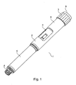
- Fig. 1 is a perspective view of an injection device 1 according to a first embodiment of the invention.
- the injection device 1 comprises a housing 2, a dose knob 3 positioned at a proximal end of the injection device 1, and a portion 4 adapted to receiving an injection needle positioned at a distal end of the injection device 1.
- the housing 2 comprises a cartridge holding portion 5 and a portion 6 being provided with a display 7 for displaying the amount of a set dose and/or the amount of an injected dose. Adjacent to the dose knob 3 an injection button 8 is positioned.
- the dose knob 3 When it is desired to inject a dose, the dose knob 3 is rotated in order to set the desired dose, and subsequently, when an injection needle has been positioned at a suitable injection site, the injection button 8 is pressed, thereby causing the set dose to be injected. This will be described further below.
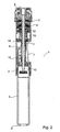
- Fig. 2 is a cross sectional view of the injection device 1 of Fig. 1 .
- the injection device 1 comprises a torsion spring 9 arranged co-axially with and surrounding a threaded piston rod 10.
- the dose knob 3 is rotated during dose setting, the torsion spring 9 is twisted, and energy is thereby stored in the torsion spring 9. This is obtained in the following manner.
- the dose knob 3 is rotationally coupled to a ratchet 11 during dose setting.
- the ratchet 11 is also connected to the torsion spring 9.
- rotating the dose knob 3 causes the ratchet 11 to rotate, thereby tensioning the torsion spring 9.
- rotating the dose knob 3 causes nut 12 to travel in a direction towards the dose knob 3 via threaded connection 13.
- the nut 12 has a function which is similar to the function of a scale drum in injection devices having mechanical detection of the amount of a set dose, i.e. the axial and angular position of the nut 12 indicates the amount of a set dose.
- the nut 12 does not have the function of displaying the set dose, contrary to the function of an ordinary scale drum. It is, therefore, not necessary to position the nut 12 in such a manner that it is readily visible. Accordingly, the nut 12 is positioned as shown in Fig. 2 , i.e. in an interior part of the injection device 1.
- the injection device 1 is further provided with a set of disc shaped members 14 being adapted to rotate relatively to each other during dose setting as well as during injection.
- the disc shaped members 14 are each provided with a layer of metal arranged in a pattern, and the disc shaped members 14 thereby form a capacitor having a capacitance which varies as a function of a relative angular displacement between the disc shaped members 14. Thereby the capacitance provides a measure for the angular displacement between the disc shaped members 14, and thereby for the amount of a set or injected dose. This will be described in further detail below.
- Electronic circuitry (not shown) is adapted to read the capacitance from the disc shaped members 14 and to communicate a corresponding dose amount to the display 7, thereby causing the relevant dose amount to be displayed to a user.
- Linear sensors are furthermore provided for monitoring axial movements of specific parts of the injection device.
- the linear sensors may be capacitively based sensors of the type generally described in US patent No. 5,731,707 .
- the disc shaped members 14 reflects the angular position of the dose knob 3, and the axial position of one or more of the linear sensors reflects the number of full turns the dose knob 3 has been dialled.
- the relative angular position of disc shaped members 14 and the axial position of the linear sensor(s) in combination are used for electronically detecting the set dose, i.e. providing an absolute detection of the dose setting.
- a similar arrangement could be used for providing an absolute detection of an injected dose.
- injection button 8 When it is desired to inject a previously set dose, injection button 8 is pressed, thereby causing the ratchet 11 to be decoupled from the housing 2. Thereby the ratchet 11 is allowed to rotate. The energy stored in the torsion spring 9 during dose setting therefore forces the ratchet 11 to rotate back to its initial position.
- the ratchet 11 is rotationally coupled to the piston rod 10, via injection ratchet 17 (visible in Figs. 5, 6 and 8 ), and the piston rod 10 will therefore also rotate during this. Since the piston rod 10 is threadedly connected to the housing 2, this rotation will cause the piston rod 10 to move in a direction towards the cartridge holding portion 5 of the housing 2. As a consequence, an amount of drug corresponding to the previously set dose will be injected from the injection device 1.
- the disc shaped members 14 perform a rotational movement relatively to each other, and the printed circuit 15 reads the corresponding capacitance and causes a corresponding amount of injected dose to be displayed in the display 7, similarly to the situation during dose setting described above.
- Figs. 3-6 are partial views of the injection device 1 of Figs. 1 and 2 at various stages of an injection operation. For the sake of clarity, parts of the injection device 1 which are not necessary for describing the injection operation have been omitted.
- Fig. 3 shows the injection device 1 in an initial position, i.e. the injection device 1 is ready for setting a dose.
- the dose knob 3 is rotated, thereby causing the torsion spring 9 to be tensed, and the disc shaped members 14 to perform a rotational movement relatively to each other, as described above.
- printed circuit 15a is caused to move in a distal direction, i.e. in a direction away from the dose knob 3, due to a connection between track 18 on ratchet extension 19 and track 20a arranged on the printed circuit 15a.
- Fig. 4 shows the injection device 1 of Figs. 1-3 in a position where a dose has been set and the injection device 1 is ready for injection.
- printed circuit 15a has been moved in a distal direction.
- the dose knob is not visible.
- the injection button 8 is pressed. This causes the ratchet 11 to be decoupled from the housing, thereby causing the energy previously stored in the torsion spring 9 to be released, the released energy rotorically driving the ratchet 11 back. As a consequence the piston rod 10 is moved in a distal direction as described above.
- Fig. 5 shows the injection device 1 of Figs. 1-4 during injection. It is clear from Fig. 5 that ratchet extension 19 has been moved in a distal direction due to operation of the injection button 8.
- Fig. 6 shows the injection device 1 of Figs. 1-5 in a position where injection has been completed. Accordingly, printed circuit 15a has been moved back to the position of Fig. 3 . Comparing Figs. 3 and 6 it is clear that injection button 8 is still in a pressed-down position in Fig. 6 , indicating that the injection has only just been completed, and that the injection device 1 is not yet ready for setting a new dose. Furthermore, it is clear that the piston rod 10 has been moved in a distal direction, indicating that a dose has been injected due to cooperation between the piston rod 10 and a piston positioned in a cartridge containing the drug to be injected.
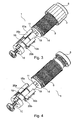
- Fig. 7 is an exploded view of electronic detection means for use in the injection device of Figs. 1-6 , in the form of a set of disc shaped members 14.
- the electronic detection means comprises two outer discs 21 arranged with a third disc 22 there between.
- the third disc 22 is provided with a pattern of metal which varies as a function of an angular position of the third disc 22.
- the outer discs 21 and the third disc 22 are able to rotate relatively to each other. Thereby, the capacitor formed by the third disc 22 and at least one of the outer discs 21 has a capacity which varies as a function of the angular displacement between the outer discs 21 and the third disc 22.
- the mechanism ensures that the moveable parts have a repeatable pattern of movement in such a way that zero always represents the same rotational position.
- the electronical reading can be made absolute, as opposed to a relative reading, thereby ensuring a high security of operation.
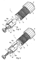
- Fig. 8 is an exploded view of the injection device 1 of Figs. 1-6 .
- Fig. 8 shows the individual parts of the injection device 1 in a clear manner.
- Fig. 9 is a perspective view of an injection device 1 according to a second embodiment of the invention.
- the injection device 1 comprises a housing 2 with a cartridge holding portion 5 and a portion 6 holding a display (not shown) arranged at 7'. At a distal end of the injection device 1 there is a portion 4 for receiving an injection needle.
- the injection device 1 is further provided with a combined dose knob and injection button 23. Thus the combined button 23 is rotated when it is desired to set a dose, and it is pressed when it is desired to inject a previously set dose.
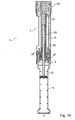
- Fig. 10 is a cross sectional view of the injection device 1 of Fig. 9 .
- the injection device 1 according to this embodiment of the invention comprises a compressible spring 24 arranged coaxially with and surrounding a threaded piston rod 10.
- the compressible spring 24 extends substantially along the entire length of the portion 6 of the housing 2 which holds the display 7.
- the injection device 1 further comprises a spring compressing member 25 which is moved in a proximal direction during dose setting, thereby causing the compressible spring 24 to be compressed, thereby storing energy in the compressible spring 24.
- the combined button 23 When it is desired to set a dose, the combined button 23 is rotated. This causes a dose rod 26 to rotate along.
- the dose rod 26 is connected to the spring compressing member 25 in such a manner that the spring compressing member 25 is also caused to rotate along with the combined button 23.
- the spring compressing member 25 is threadedly engaged with the piston rod 10 which, on the other hand, is prevented from rotating due to first locking member 27, and from axial movement due to second locking member 28, also threadedly engaged with the piston rod 10. Accordingly, rotating the spring compressing member 25 results in the spring compressing member 25 moving along the thread of the piston rod 10 in a proximal direction, thereby causing the compressible spring 24 to be compressed.
- the combined button 23 is pressed axially in a distal direction.
- Longitudinal member 30 is moved along, thereby setting the second locking member 28 free to rotate in a manner which will be described in further detail below.
- the piston rod 10 is allowed to move axially.
- the compressed spring 24 will then push the spring compressing member 25 in a distal direction, and the threaded connection between the spring compressing member 25 and the piston rod 10 will cause the piston rod 10 to move in a distal direction, thereby causing the set dose to be injected.
- the spring compressing member 25 will enter into abutment with the second locking member 28, the second locking member 28 thereby functioning as an abutment member, thereby preventing that a dose exceeding the set dose is injected.
- the injection device is provided with a click mechanism providing audible and/or tactile clicks during rotational operation of the combined button 23 so that each click corresponds to a pre-defined dose increment.
- a click mechanism preferably also provides positioning of combined button 23 in discrete operational steps such as 24, 36 or 48 steps per revolution.
- the click mechanism is provided by a stepped cam surface of combined button 23 which co-operates with a corresponding cam surface which is rotationally fixed with respect to the housing (best seen in Figs. 11-15 ).
- the two opposing cam surfaces are biased towards each other by the compressible spring 24 causing the clicks to be very self indexing and preventing that the system tends to run by it self when resetting a dose.
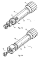
- Figs. 11-14 are partial views of the injection device 1 of Figs. 9 and 10 at various stages of an injection operation, i.e. during setting of a dose and injection of the set dose. For the sake of clarity, parts which are not essential for the operation of the injection device 1 have been omitted.
- Fig. 11 shows the injection device 1 in a position where it is ready for setting a dose.
- the combined button 23 is rotated as described above, thereby causing the dose rod 26, acting as a spring compressing member, to move in a proximal direction.
- the second locking member 28 is in engagement with a set of teeth 29 positioned on a longitudinal member 30 which is fixed rotationally to the housing. The second locking member 28 is thereby prevented from rotating relatively to the housing, and the piston rod 10 is thereby prevented from moving axially relatively to the housing.
- Fig. 12 shows the injection device 1 in a position where a dose has been set and the injection device 1 is ready for injecting the set dose. It is clear from Fig. 12 that the dose rod 26 has been moved in a proximal direction. The second locking member 28 is still in engagement with the set of teeth 29, i.e. the piston rod 10 is still prevented from moving axially relatively to the housing.
- the combined button 23 is pressed, thereby pushing the longitudinal member 30 in a distal direction.
- the set of teeth 29 is moved out of engagement with the second locking member 28.
- the second locking member 28 will be able to rotate relatively to the housing, and the piston rod 10 will thereby be allowed to move axially relatively to the housing.
- Fig. 13 shows the injection device 1 during injection of a previously set dose. It is clear from Fig. 13 that the second locking member 28 and the set of teeth 29 are not engaging, and that the second locking member 28 is therefore able to rotate relatively to the housing, thereby allowing axial movement of the piston rod 10. Accordingly, the piston rod 10 is able to cause a set dose to be injected.
- Fig. 14 shows the injection device 1 in a position where injection of a set dose has been completed. Comparing Fig. 11 and Fig. 14 it is clear that the second locking member 28 is not in engagement with the set of teeth (not visible in Fig. 14 ), and that the injection device 1 is therefore not yet ready for setting a new dose. Furthermore, the piston rod 10 has been moved in a distal direction, indicating that a dose has been injected.
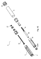
- Fig. 15 is an exploded view of the injection device of Figs. 9-14 .
- Fig. 15 shows the individual parts of the injection device 1 in a clear manner.
- Figs. 16-21 show various illustrations of an injection device 1 according to a third embodiment of the invention.
- the injection device 1 according to the third embodiment of the invention is operated essentially as the injection device 1 according to the second embodiment which is described above with reference to Figs. 9-15 . Accordingly, the operation of the injection device 1 according to the third embodiment of the invention will not be described in details here.
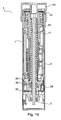
- Fig. 16 is a cross sectional view of an injection device 1 according to a third embodiment of the invention. For the sake of clarity, only the portion 6 of the housing 2 which holds the display 7 is shown, the cartridge holding part being omitted. In Fig. 16 the injection device 1 is shown in a position where it is ready for setting a dose.
- the injection device 1 is provided with a first set of disc shaped members 31 arranged at a position near the combined button 23.
- the first set of disc shaped members 31 functions essentially as the set of disc shaped members 14 described above with reference to Figs. 1-8 .
- the disc shaped members 31 perform relative rotational movements, and thereby the capacitance of the capacitor formed by the disc shaped members 31 varies. Thereby the set dose can be electronically detected. This will be described further below with reference to Figs. 19-21 .
- the injection device 1 is further provided with a second set of disc shaped members 32 arranged at a distal position of the portion 6 holding the display 7.
- the second set of disc shaped members 32 also functions essentially as the disc shaped members 14 described above with reference to Figs. 1-8 .
- the piston rod 10 causes the second locking member 28 to rotate.
- the discs of the second set of disc shaped members 32 are caused to perform relative rotational movements, and thereby the capacitance of the capacitor formed by the disc shaped members 32 varies.
- the injected dose can be electronically detected. This will be described further below with reference to Figs. 19-21 .
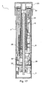
- Fig. 17 is a cross sectional view of the injection device 1 of Fig. 16 .
- a dose has been set, i.e. spring compressing member 25 has been moved in a proximal direction, and thereby compressible spring 24 has been compressed, i.e. energy has been stored in the compressible spring 24.
- Fig. 18 is a cross sectional view of the injection device 1 of Figs. 16 and 17 .
- the set dose has been injected. It can be seen that the piston rod 10 has been moved in a distal direction as compared to the situation shown in Fig. 16 . Delivering of the dose has only just been completed.
- the combined button 23 is still in a pressed-down position, thereby keeping the second locking member 28 and the longitudinal member 30 out of engagement, the second locking member 28 thereby being able to perform a rotational movement, allowing the piston rod 10 to move in a distal direction.
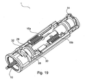
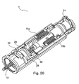
- Figs. 19-21 are partial views of the injection device 1 of Figs. 16-18 at the stages of an injection operation which are also shown in these Figures. For the sake of clarity, parts which are not essential for the operation of the injection device 1 have been omitted.
- Fig. 19 shows the injection device 1 in position where it is ready for setting a dose, i.e. it corresponds to Fig. 16 .
- printed circuits 15a and 15b can be seen.
- the capacitance of the capacitor formed by the first set of disc shaped members 31 reflects the angular position of the combined button 23, and the axial position of the printed circuit 15a reflects the number of full turns the combined button 23 has been dialled.
- the relative angular position of the first set of disc shaped members 31 and the axial position of the printed circuit 15a in combination are used for electronically detecting the set dose, i.e. providing an absolute detection of the dose setting.
- the set dose could in principle be detected electronically using only the first set of disc shaped members 31, i.e. without the use of printed circuit 15a.
- Such an embodiment may include an electronic circuitry which electronically monitors the number of complete revolutions that the combined button 23 undertakes during operation thereof, said monitoring being exclusively based upon signals received from the first set of disc shaped members 31.
- the operation of the dose setting member is limited to 360 degrees operation or less, such that any dose which it may be desired to set can be set within a single turn of the combined button 23.
- a single unit of a dose would, in this case, correspond to the combined button 23 being rotated through a very small angle, and the first set of disc shaped members 31 would therefore need to be designed in such a manner that such small variations in relative angular position between the discs are detectable.
- Fig. 20 shows the injection device 1 in a position where a dose has been set and is ready to be injected.
- Fig. 20 corresponds to Fig. 17 . It can be seen that the printed circuit 15a has been moved in a proximal direction relatively to the situation shown in Fig. 19 .
- the combined button (not shown) is pressed in, and longitudinal member 30 is moved along in a distal direction.
- the set of teeth 29 formed on the longitudinal member 30 are moved out of engagement with the corresponding set of teeth formed on the second locking member 28, and the second locking member 28 is allowed to rotate as described above, thereby causing the discs of the second set of disc shaped members 32 to perform relative rotational movements.
- the printed circuit 15b is caused to move axially in a distal direction. The axial position of the printed circuit 15b provides an indication as to whether the injection device is in dose setting mode or injection mode.
- injection of a set dose causes printed circuit 15a to move in a distal direction, thereby returning to the initial position.
- Fig. 21 shows the injection device 1 in a position where a set dose has just been injected.
- Fig. 21 corresponds to Fig. 18 .
- the printed circuit 15a has been returned to its initial position, and that the printed circuit 15b has been moved in a distal direction.
- the teeth 29 are still out of engagement with the teeth of the second locking member 28.
- the disclosed mechanisms provide space efficient designs of spring assisted injection devices which makes room available for accommodating electronic circuitry such as an electronic display, sensors etc.
- the designs are suitable for injection devices having an electronic display mounted fixedly with respect to the device housing while simultaneously providing reliable routing of the wiring to the various sensor components.
- the designs are optimized for spring assisted injection devices where the sensing of rotational parts during both dose setting and injection operations are made feasible.
Landscapes
- Health & Medical Sciences (AREA)
- Engineering & Computer Science (AREA)
- Animal Behavior & Ethology (AREA)
- General Health & Medical Sciences (AREA)
- Biomedical Technology (AREA)
- Heart & Thoracic Surgery (AREA)
- Hematology (AREA)
- Life Sciences & Earth Sciences (AREA)
- Vascular Medicine (AREA)
- Anesthesiology (AREA)
- Public Health (AREA)
- Veterinary Medicine (AREA)
- Power Engineering (AREA)
- Physics & Mathematics (AREA)
- General Physics & Mathematics (AREA)
- Infusion, Injection, And Reservoir Apparatuses (AREA)
Priority Applications (2)
| Application Number | Priority Date | Filing Date | Title |
|---|---|---|---|
| EP07820718A EP2073871B1 (en) | 2006-09-29 | 2007-09-28 | An injection device with electronic detecting means |
| PL07820718T PL2073871T3 (pl) | 2006-09-29 | 2007-09-28 | Urządzenie wstrzykujące z elektronicznymi środkami wykrywającymi |
Applications Claiming Priority (3)
| Application Number | Priority Date | Filing Date | Title |
|---|---|---|---|
| EP06020547 | 2006-09-29 | ||
| EP07820718A EP2073871B1 (en) | 2006-09-29 | 2007-09-28 | An injection device with electronic detecting means |
| PCT/EP2007/060331 WO2008037801A1 (en) | 2006-09-29 | 2007-09-28 | An injection device with electronic detecting means |
Publications (2)
| Publication Number | Publication Date |
|---|---|
| EP2073871A1 EP2073871A1 (en) | 2009-07-01 |
| EP2073871B1 true EP2073871B1 (en) | 2013-03-20 |
Family
ID=37779398
Family Applications (1)
| Application Number | Title | Priority Date | Filing Date |
|---|---|---|---|
| EP07820718A Active EP2073871B1 (en) | 2006-09-29 | 2007-09-28 | An injection device with electronic detecting means |
Country Status (12)
| Country | Link |
|---|---|
| US (2) | US8052655B2 (OSRAM) |
| EP (1) | EP2073871B1 (OSRAM) |
| JP (1) | JP5113847B2 (OSRAM) |
| CN (2) | CN101516421B (OSRAM) |
| AU (1) | AU2007301890B2 (OSRAM) |
| BR (1) | BRPI0717260A2 (OSRAM) |
| CA (1) | CA2663239C (OSRAM) |
| DK (1) | DK2073871T3 (OSRAM) |
| ES (1) | ES2411732T3 (OSRAM) |
| PL (1) | PL2073871T3 (OSRAM) |
| RU (1) | RU2453343C2 (OSRAM) |
| WO (1) | WO2008037801A1 (OSRAM) |
Families Citing this family (168)
| Publication number | Priority date | Publication date | Assignee | Title |
|---|---|---|---|---|
| US6663602B2 (en) | 2000-06-16 | 2003-12-16 | Novo Nordisk A/S | Injection device |
| ATE409057T1 (de) | 2002-02-11 | 2008-10-15 | Antares Pharma Inc | Intradermales injektionsgerät |
| ZA200703707B (en) | 2004-10-21 | 2009-02-25 | Novo Nordisk As | Dial-Down Mechanism for Wind-up Pen |
| WO2006079064A1 (en) | 2005-01-24 | 2006-07-27 | Antares Pharma, Inc. | Prefilled needle assisted jet injector |
| EP1877121B1 (en) | 2005-04-24 | 2015-09-23 | Novo Nordisk A/S | Injection device |
| WO2007131025A1 (en) | 2006-05-03 | 2007-11-15 | Antares Pharma, Inc. | Injector with adjustable dosing |
| US8251947B2 (en) | 2006-05-03 | 2012-08-28 | Antares Pharma, Inc. | Two-stage reconstituting injector |
| WO2007132019A1 (en) | 2006-05-16 | 2007-11-22 | Novo Nordisk A/S | A gearing mechanism for an injection device |
| PL2023982T3 (pl) | 2006-05-18 | 2012-11-30 | Novo Nordisk As | Urządzenie wstrzykujące ze środkami blokującymi |
| WO2008008281A2 (en) | 2006-07-07 | 2008-01-17 | Proteus Biomedical, Inc. | Smart parenteral administration system |
| BRPI0717260A2 (pt) | 2006-09-29 | 2013-10-15 | Novo Nordisk As | Dispositivos de injeção com meio de detecção eletrônica |
| RU2468829C2 (ru) * | 2007-03-23 | 2012-12-10 | Ново Нордиск А/С | Инъекционное устройство, содержащее стопорную гайку |
| EP2190506B1 (en) | 2007-08-17 | 2011-08-17 | Novo Nordisk A/S | Medical device with value sensor |
| WO2009055733A1 (en) | 2007-10-25 | 2009-04-30 | Proteus Biomedical, Inc. | Fluid transfer port information system |
| DE102007054868A1 (de) * | 2007-11-07 | 2009-05-20 | Arzneimittel Gmbh Apotheker Vetter & Co. Ravensburg | Vorrichtung und Verfahren zur Montage einer pharmazeutischen Applikationshilfe |
| WO2009067463A1 (en) | 2007-11-19 | 2009-05-28 | Proteus Biomedical, Inc. | Body-associated fluid transport structure evaluation devices |
| ATE555822T1 (de) | 2007-12-31 | 2012-05-15 | Novo Nordisk As | Elektronisch überwachte injektionsvorrichtung |
| JP5731829B2 (ja) | 2008-03-10 | 2015-06-10 | アンタレス・ファーマ・インコーポレーテッド | 注射器安全装置 |
| DK2296732T3 (da) * | 2008-06-11 | 2014-04-07 | Shl Group Ab | Medikamentafgivelsesindretning |
| EP3581224A1 (en) | 2008-08-05 | 2019-12-18 | Antares Pharma, Inc. | Multiple dosage injector |
| JP5715959B2 (ja) * | 2008-11-17 | 2015-05-13 | ベクトン・ディキンソン・アンド・カンパニーBecton, Dickinson And Company | 薬物皮内注射用薬物送達ペンのための力付加装置 |
| WO2010088973A1 (en) * | 2009-02-06 | 2010-08-12 | Shl Group Ab | Medicament delivery device with electronic dose sensor |
| AU2010226442A1 (en) | 2009-03-20 | 2011-10-13 | Antares Pharma, Inc. | Hazardous agent injection system |
| US20130123685A1 (en) * | 2009-06-03 | 2013-05-16 | Novo Nordisk A/S | Electronically monitored injection device |
| PL215310B1 (pl) * | 2009-10-30 | 2013-11-29 | Kappa Medilab Spolka Z Ograniczona Odpowiedzialnoscia | Automatyczny aplikator, zwlaszcza do insuliny |
| EP2327431A1 (en) | 2009-11-25 | 2011-06-01 | Letcat Aktiebolag | Medical delivery device |
| US8332020B2 (en) | 2010-02-01 | 2012-12-11 | Proteus Digital Health, Inc. | Two-wrist data gathering system |
| BR112012019212A2 (pt) | 2010-02-01 | 2017-06-13 | Proteus Digital Health Inc | sistema de coleta de dados |
| WO2011136718A1 (en) * | 2010-04-26 | 2011-11-03 | Shl Group Ab | Medicament delivery device |
| WO2012046199A1 (en) * | 2010-10-05 | 2012-04-12 | Hendrik Meiring | Liquid dosage monitoring |
| JP6616073B2 (ja) | 2011-03-24 | 2019-12-04 | サノフィ−アベンティス・ドイチュラント・ゲゼルシャフト・ミット・ベシュレンクテル・ハフツング | 医療デバイスで実行可能な作動動作を検出するためのデバイス及び方法 |
| MY164000A (en) * | 2011-03-25 | 2017-11-15 | Sanofi Aventis Deutschland | Dose setting mechanism and injection device |
| EP3865054A1 (en) | 2011-03-30 | 2021-08-18 | Novo Nordisk A/S | System for optimizing a patient s drug dosage regimen over time |
| WO2012140097A2 (en) | 2011-04-11 | 2012-10-18 | Novo Nordisk A/S | Injection device incorporating dose monitoring |
| WO2012152628A1 (en) | 2011-05-06 | 2012-11-15 | Novo Nordisk A/S | System for optimizing a drug dosage regimen over time |
| US20130085349A1 (en) | 2011-06-21 | 2013-04-04 | Yofimeter, Llc | Analyte testing devices |
| EP2729202B2 (en) | 2011-07-07 | 2024-11-06 | Novo Nordisk A/S | Drug delivery injection pen with add-on dose capturing and display module |
| CN103649689B (zh) * | 2011-07-15 | 2016-12-14 | 赛诺菲-安万特德国有限公司 | 药物递送装置 |
| US8496619B2 (en) | 2011-07-15 | 2013-07-30 | Antares Pharma, Inc. | Injection device with cammed ram assembly |
| US9220660B2 (en) | 2011-07-15 | 2015-12-29 | Antares Pharma, Inc. | Liquid-transfer adapter beveled spike |
| EP2731644B1 (en) | 2011-07-15 | 2019-02-20 | Sanofi-Aventis Deutschland GmbH | Drug delivery device with electro-mechanic drive mechanism |
| CN103917974A (zh) | 2011-08-18 | 2014-07-09 | 诺沃—诺迪斯克有限公司 | 具有用于处置数据的器件的药物递送装置 |
| EP2798546B1 (en) | 2011-09-13 | 2020-12-23 | Novo Nordisk A/S | Adaptive system for optimizing a drug dosage regimen over time |
| US20140378801A1 (en) | 2011-09-27 | 2014-12-25 | Novo Nordisk A/S | Medical System Configured to Collect and Transfer Data |
| JP6109834B2 (ja) | 2011-10-07 | 2017-04-05 | ノボ・ノルデイスク・エー/エス | 3軸磁気センサに基づいて要素の位置を決定するシステム |
| RU2014128518A (ru) | 2011-12-29 | 2016-02-20 | Ново Нордиск А/С | Механизм увеличения/уменьшения дозы для взводимого шприца-ручки |
| WO2013120778A1 (en) * | 2012-02-13 | 2013-08-22 | Sanofi-Aventis Deutschland Gmbh | Pen-type drug injection device and electronic add-on monitoring module for monitoring and logging dose setting and administration |
| PT2822618T (pt) | 2012-03-06 | 2024-03-04 | Antares Pharma Inc | Seringa pré-cheia com característica de força de rutura |
| EP2833944A4 (en) | 2012-04-06 | 2016-05-25 | Antares Pharma Inc | ADMINISTRATION OF TESTOSTERONE COMPOSITIONS BY NEEDLE-SUPPORTED NOZZLE INJECTION |
| US9364610B2 (en) | 2012-05-07 | 2016-06-14 | Antares Pharma, Inc. | Injection device with cammed ram assembly |
| HK1211507A1 (en) * | 2012-08-10 | 2016-05-27 | Sanofi-Aventis Deutschland Gmbh | Pen-type drug injection device and electronic add-on monitoring module for monitoring and logging dose setting and administration |
| EP2698179A1 (en) * | 2012-08-14 | 2014-02-19 | Sanofi-Aventis Deutschland GmbH | Injection device |
| WO2014037331A1 (en) * | 2012-09-06 | 2014-03-13 | Sanofi-Aventis Deutschland Gmbh | Pen-type drug injection device and electronic add-on monitoring module for monitoring and logging dose setting and administration |
| GB2508588A (en) * | 2012-11-30 | 2014-06-11 | Owen Mumford Ltd | Medical delivery device comprising mechanical-electrical transducer |
| JP6423362B2 (ja) * | 2013-01-10 | 2018-11-14 | ノボ・ノルデイスク・エー/エス | 用量収集機能を有する医療注射システム |
| JP6366607B2 (ja) | 2013-01-15 | 2018-08-01 | サノフィ−アベンティス・ドイチュラント・ゲゼルシャフト・ミット・ベシュレンクテル・ハフツング | 注射デバイスの使用についての使用レポートをデジタル画像形式で生成するために医療注射デバイスに取り付ける補助デバイス |
| JP6411369B2 (ja) * | 2013-01-15 | 2018-10-24 | サノフィ−アベンティス・ドイチュラント・ゲゼルシャフト・ミット・ベシュレンクテル・ハフツング | 復号システム |
| PT2953667T (pt) | 2013-02-11 | 2020-01-28 | Antares Pharma Inc | Dispositivo de injeção a jato auxiliado por agulha tendo força de gatilho reduzida |
| WO2014128157A1 (en) | 2013-02-19 | 2014-08-28 | Novo Nordisk A/S | Drug delivery device with dose capturing module |
| EP2958610B1 (en) * | 2013-02-19 | 2016-11-30 | Novo Nordisk A/S | Dose capturing cartridge module for drug delivery device |
| WO2014128156A1 (en) | 2013-02-19 | 2014-08-28 | Novo Nordisk A/S | Rotary sensor module with axial switch |
| CN111442791A (zh) * | 2013-03-04 | 2020-07-24 | 德康公司 | 用于检测器组件的电线密封件 |
| JP6030803B2 (ja) | 2013-03-11 | 2016-11-24 | アンタレス・ファーマ・インコーポレーテッド | ピニオンシステムを有する用量注射器 |
| WO2014165136A1 (en) | 2013-03-12 | 2014-10-09 | Antares Pharma, Inc. | Constant volume prefilled syringes and kits thereof |
| EP2981310B1 (en) | 2013-04-05 | 2017-07-12 | Novo Nordisk A/S | Dose logging device for a drug delivery device |
| CN105120925B (zh) * | 2013-04-05 | 2018-11-06 | 诺和诺德股份有限公司 | 药物输送设备和记录模块组件 |
| CN105120924B (zh) | 2013-04-05 | 2019-05-28 | 诺和诺德股份有限公司 | 具有集成磁性运动指示器的药物输送设备 |
| CN105102024B (zh) | 2013-04-05 | 2019-02-05 | 诺和诺德股份有限公司 | 适合于将剂量组合的记录设备 |
| NO2983762T3 (OSRAM) * | 2013-04-10 | 2018-02-10 | ||
| US10232118B2 (en) * | 2013-04-10 | 2019-03-19 | Sanofi | Drive assembly for a drug delivery device |
| MX2015014291A (es) | 2013-04-10 | 2016-01-20 | Sanofi Sa | Dispositivo de inyeccion. |
| CN105228678B (zh) | 2013-04-22 | 2019-09-27 | 赛诺菲-安万特德国有限公司 | 具有oled的传感器装置 |
| WO2014180745A1 (en) * | 2013-05-07 | 2014-11-13 | Sanofi-Aventis Deutschland Gmbh | Supplemental device for attachment to an injection device |
| CN105209095A (zh) * | 2013-05-21 | 2015-12-30 | 诺和诺德股份有限公司 | 具有活塞杆联轴器的药物输送装置 |
| JP6382956B2 (ja) | 2013-05-21 | 2018-08-29 | ノボ・ノルデイスク・エー/エス | 動的な軸方向ストッパ特徴を有する前方装填式の薬剤送達装置 |
| DK3003439T3 (da) * | 2013-05-27 | 2021-09-13 | Sanofi Aventis Deutschland | Enhed til en anordning til indgivelse af lægemidler samt anordning til indgivelse af lægemidler |
| AT514484B1 (de) * | 2013-06-24 | 2015-05-15 | Pharma Consult Gmbh | Aktivator für einen Autoinjektor |
| US11311678B2 (en) | 2013-11-21 | 2022-04-26 | Novo Nordisk A/S | Rotary sensor assembly with space efficient design |
| JP6786389B2 (ja) | 2013-11-21 | 2020-11-18 | ノボ・ノルデイスク・エー/エス | 軸方向スイッチおよび冗長化機構を備えた回転センサアセンブリ |
| EP3071260A1 (en) | 2013-11-21 | 2016-09-28 | Novo Nordisk A/S | Rotary sensor module with resynchronization feature |
| US10512732B2 (en) | 2013-11-22 | 2019-12-24 | Sanofi-Aventis Deutschland Gmbh | Drug delivery device with dose knob clutch |
| EP2881131B1 (de) * | 2013-12-05 | 2019-04-24 | TecPharma Licensing AG | Antriebs- und Dosiervorrichtung für eine Injektionsvorrichtung mit einer vorgespannten Antriebsfeder |
| GB201402826D0 (en) | 2014-02-18 | 2014-04-02 | Owen Mumford Ltd | Injection device |
| JP2017514552A (ja) * | 2014-03-31 | 2017-06-08 | サノフィ−アベンティス・ドイチュラント・ゲゼルシャフト・ミット・ベシュレンクテル・ハフツング | 特定用量スケールと、設定用量値を明確に表示するための光学フィルタを含む用量表示窓とを有するペン型薬物注射デバイス |
| CN106659842B (zh) | 2014-06-06 | 2019-12-24 | 诺和诺德股份有限公司 | 用于药物输送设备的记录设备 |
| CN106413781B (zh) | 2014-06-06 | 2020-04-21 | 诺和诺德股份有限公司 | 由药物输送设备操作的记录设备 |
| US10603442B2 (en) | 2014-08-25 | 2020-03-31 | Novo Nordisk A/S | Accessory device with snap feature |
| US10704944B2 (en) | 2014-09-14 | 2020-07-07 | Becton, Dickinson And Company | System and method for capturing dose information |
| US10971260B2 (en) | 2014-09-14 | 2021-04-06 | Becton, Dickinson And Company | System and method for capturing dose information |
| WO2016050902A1 (en) | 2014-10-03 | 2016-04-07 | Novo Nordisk A/S | Pen-type drug injector and add-on module with magnetic dosage sensor system and error detection |
| WO2016062807A1 (en) | 2014-10-23 | 2016-04-28 | Novo Nordisk A/S | Pen-type drug delivery device with electronic display on clip member |
| WO2016102526A1 (en) * | 2014-12-22 | 2016-06-30 | Novo Nordisk A/S | Spring-driven drug delivery device |
| AU2015372441A1 (en) | 2014-12-23 | 2017-08-10 | Automed Pty Ltd | Delivery apparatus, system and associated methods |
| EP3058970A1 (en) | 2015-02-19 | 2016-08-24 | Sanofi-Aventis Deutschland GmbH | Data collection device for attachment to an injection device |
| WO2016135236A1 (en) * | 2015-02-27 | 2016-09-01 | Novo Nordisk A/S | Accessory device with mounting safety feature |
| EP3067081A1 (en) | 2015-03-12 | 2016-09-14 | Sanofi | Drug delivery device |
| US10556066B2 (en) | 2015-05-29 | 2020-02-11 | Novo Nordisk A/S | Power efficient electronic device |
| JP6901975B2 (ja) | 2015-06-09 | 2021-07-14 | サノフィ−アベンティス・ドイチュラント・ゲゼルシャフト・ミット・ベシュレンクテル・ハフツング | 注射デバイスに取り付けられるデータ収集装置 |
| EP3319665B1 (en) | 2015-07-06 | 2025-07-02 | Battelle Memorial Institute | Autoinjector device for injections with increased patient comfort |
| AU2016291849B2 (en) | 2015-07-12 | 2021-09-23 | Patients Pending Ltd. | Cover for liquid delivery system with integrated plunger position sensing, and corresponding method |
| WO2017009102A1 (en) * | 2015-07-13 | 2017-01-19 | Novo Nordisk A/S | Drug delivery device with end-of-dose trigger arrangement |
| JP6837483B2 (ja) | 2015-11-11 | 2021-03-03 | ノボ・ノルデイスク・エー/エス | 情報の捕捉を伴う薬剤送達装置 |
| JP6907212B2 (ja) | 2015-12-28 | 2021-07-21 | ノボ・ノルデイスク・エー/エス | 低電力フィーチャーを備えたロータリーセンサアセンブリ |
| DK3400045T3 (da) | 2016-01-06 | 2020-08-10 | Sanofi Aventis Deutschland | Medikamentadministrationsanordning |
| WO2017132577A1 (en) | 2016-01-29 | 2017-08-03 | Companion Medical, Inc. | Automatic medication delivery tracking |
| WO2017148855A1 (en) | 2016-03-01 | 2017-09-08 | Novo Nordisk A/S | Switch arrangement for drug delivery device with data capture |
| JP7201435B6 (ja) | 2016-03-01 | 2023-01-23 | ノボ・ノルデイスク・エー/エス | 電力効率の良いアクセサリデバイス |
| US10857304B2 (en) | 2016-03-25 | 2020-12-08 | Eli Lilly And Company | Determination of a dose set and delivered in a medication delivery device |
| WO2017184401A1 (en) | 2016-04-19 | 2017-10-26 | Eli Lilly And Company | Determination of a dose in a medication delivery device using two moving arrays with teeth and a sensor |
| US20190117899A1 (en) | 2016-04-28 | 2019-04-25 | Novo Nordisk A/S | Accessory device with zero position adjustment feature |
| EP3448470B1 (en) | 2016-04-29 | 2020-03-18 | Novo Nordisk A/S | Drug delivery system with dose capturing |
| CN109310828B (zh) | 2016-05-30 | 2022-09-16 | 诺和诺德股份有限公司 | 用于附件装置的安装特征 |
| CN109152884B (zh) | 2016-05-30 | 2022-02-11 | 诺和诺德股份有限公司 | 具有零位置调节特征的药物输送装置 |
| US9636464B1 (en) * | 2016-08-01 | 2017-05-02 | Innovative Precision Instruments Limited | Drug delivery device and a drug information detection device |
| JP6718554B2 (ja) * | 2016-08-12 | 2020-07-08 | イーライ リリー アンド カンパニー | 薬剤送達デバイスにおける用量の判定 |
| US20190262541A1 (en) | 2016-10-31 | 2019-08-29 | Novo Nordisk A/S | Image capture device with viewing functionality |
| WO2018100124A1 (en) | 2016-12-01 | 2018-06-07 | Novo Nordisk A/S | Drug delivery device with clutch feature |
| WO2018100126A1 (en) | 2016-12-01 | 2018-06-07 | Novo Nordisk A/S | Drug delivery device with torsion spring feature |
| JP6993413B2 (ja) | 2016-12-05 | 2022-01-13 | ノボ・ノルデイスク・エー/エス | ペアリング機能を備える付属デバイス |
| CN110049794B (zh) | 2016-12-15 | 2021-11-16 | 伊莱利利公司 | 具有感测系统的药物输送装置 |
| EP3348298A1 (en) | 2017-01-16 | 2018-07-18 | Novo Nordisk A/S | Drug delivery device with rotationally geared piston rod driver |
| RS67428B1 (sr) | 2017-02-28 | 2025-12-31 | Lilly Co Eli | Detekcija doze i identifikacija leka za uređaj za isporuku leka |
| JP2020509876A (ja) | 2017-03-14 | 2020-04-02 | ノボ・ノルデイスク・エー/エス | カートリッジを有するキャップアセンブリ |
| JP7042838B2 (ja) | 2017-03-15 | 2022-03-28 | ノボ・ノルデイスク・エー/エス | 二次画像分析機能を有する用量捕捉アセンブリ |
| CN110573200A (zh) | 2017-05-09 | 2019-12-13 | 诺和诺德股份有限公司 | 具有声换能器的药物递送装置 |
| WO2018206439A1 (en) | 2017-05-09 | 2018-11-15 | Novo Nordisk A/S | Flexible electronic label device |
| WO2019001919A1 (en) | 2017-06-27 | 2019-01-03 | Novo Nordisk A/S | ACCESSORY DEVICE HAVING A MATCHING ELEMENT |
| CN115445029B (zh) | 2017-08-31 | 2025-02-11 | 伊莱利利公司 | 用于药物递送装置的具有压电感测的剂量检测 |
| DK3684447T3 (da) | 2017-09-22 | 2022-10-03 | Novo Nordisk As | Tilbehørsindretning til lægemiddelleveringsindretning |
| US20200230325A1 (en) | 2017-09-30 | 2020-07-23 | Novo Nordisk A/S | Cartridge system for a drug delivery device |
| USD888942S1 (en) * | 2018-04-10 | 2020-06-30 | Janssen Pharmaceuticals, Inc. | Injection device |
| MX2020005338A (es) | 2017-11-23 | 2020-10-14 | Sanofi Sa | Dispositivo de inyección de medicamento con codificador rotatorio. |
| US11684722B2 (en) | 2017-12-04 | 2023-06-27 | Novo Nordisk A/S | Drug delivery system with multipolar magnet and sensor system |
| US11197964B2 (en) | 2017-12-12 | 2021-12-14 | Bigfoot Biomedical, Inc. | Pen cap for medication injection pen having temperature sensor |
| US11464459B2 (en) | 2017-12-12 | 2022-10-11 | Bigfoot Biomedical, Inc. | User interface for diabetes management systems including flash glucose monitor |
| US11116899B2 (en) | 2017-12-12 | 2021-09-14 | Bigfoot Biomedical, Inc. | User interface for diabetes management systems and devices |
| US11077243B2 (en) | 2017-12-12 | 2021-08-03 | Bigfoot Biomedical, Inc. | Devices, systems, and methods for estimating active medication from injections |
| US10987464B2 (en) | 2017-12-12 | 2021-04-27 | Bigfoot Biomedical, Inc. | Pen cap for insulin injection pens and associated methods and systems |
| AU2018383743A1 (en) | 2017-12-12 | 2020-07-23 | Bigfoot Biomedical, Inc. | Therapy assist information and/or tracking device and related methods and systems |
| US11083852B2 (en) | 2017-12-12 | 2021-08-10 | Bigfoot Biomedical, Inc. | Insulin injection assistance systems, methods, and devices |
| AU2019208338B2 (en) | 2018-01-19 | 2024-11-07 | Birya Biotech, Inc. | Tool for servicing an auto-injector |
| EP3755402B1 (en) * | 2018-02-20 | 2026-01-28 | Novo Nordisk A/S | Accessory device with mounting feature for engaging dial member |
| SI3755404T1 (sl) | 2018-02-22 | 2023-11-30 | Eli Lilly And Company | Modul sistema za zaznavanje odmerka za napravo za dostavo zdravila |
| CN111868835A (zh) | 2018-03-09 | 2020-10-30 | 诺和诺德股份有限公司 | 用于带记录特征的医疗装置的传输协议 |
| CN111971753A (zh) | 2018-04-03 | 2020-11-20 | 诺和诺德股份有限公司 | 数据传输安全特征 |
| WO2019219824A1 (en) | 2018-05-18 | 2019-11-21 | Novo Nordisk A/S | Sensor assembly with identifier determination |
| EP3793646A1 (en) | 2018-05-18 | 2021-03-24 | Novo Nordisk A/S | Drug delivery assembly with information capture |
| US11185636B2 (en) | 2018-07-26 | 2021-11-30 | Verily Life Sciences Llc | Electrostatic rotary encoder |
| US12205699B1 (en) | 2018-10-30 | 2025-01-21 | Bigfoot Biomedical, Inc. | Method of pairing therapy devices using shared secrets, and related systems, methods and devices |
| JP2022512884A (ja) | 2018-11-06 | 2022-02-07 | ノボ・ノルデイスク・エー/エス | 特徴をサンプリングするセンサを有する薬剤送達アセンブリ |
| WO2020115031A1 (en) | 2018-12-04 | 2020-06-11 | Novo Nordisk A/S | Drug delivery assembly with moving sensor system |
| US11109800B2 (en) | 2019-01-04 | 2021-09-07 | Enable Injections, Inc. | Medical fluid injection apparatus and method with detachable patch and monitoring |
| AU2019419507B2 (en) | 2019-01-04 | 2025-09-18 | Enable Injections, Inc. | Medical fluid injection apparatus and method with detachable patch and monitoring |
| WO2020169706A1 (en) * | 2019-02-22 | 2020-08-27 | Mysugr Gmbh | Insulin delivery arrangement and method for insulin dosing |
| US11948671B2 (en) | 2019-04-11 | 2024-04-02 | Medtronic Minimed, Inc. | Intelligent accessories for medicine dispensing device |
| US20220203039A1 (en) * | 2019-05-03 | 2022-06-30 | Sanofi | Rotation Sensing Arrangement for an Injection Device |
| IL267610A (en) * | 2019-06-24 | 2019-10-31 | Dali Medical Devices Ltd | dose monitoring |
| US20220370723A1 (en) | 2019-12-03 | 2022-11-24 | Novo Nordisk A/S | Dose setting assembly with slack reducing feature |
| RU2733692C1 (ru) * | 2020-01-24 | 2020-10-06 | Александр Александрович Петров | Шприц-ручка |
| CH715791A2 (de) * | 2020-03-26 | 2020-07-31 | Ypsomed Ag | Autoinjektor mit Aussschüttdetektion, Verfahren zu dessen Vorbereitung und Antriebseinheit dafür. |
| US11957542B2 (en) | 2020-04-30 | 2024-04-16 | Automed Patent Holdco, Llc | Sensing complete injection for animal injection device |
| JP2023532586A (ja) | 2020-07-08 | 2023-07-28 | ノボ・ノルデイスク・エー/エス | アルゴリズム自動較正を有する用量設定センサ組立品 |
| EP4237045A1 (en) | 2020-10-30 | 2023-09-06 | Novo Nordisk A/S | Dose logging sensor system with error detection feature |
| US20240001038A1 (en) | 2020-11-24 | 2024-01-04 | Novo Nordisk A/S | Fast data transmission feature for medical logging device |
| JP2025507995A (ja) | 2022-03-10 | 2025-03-21 | ノボ・ノルデイスク・エー/エス | 回転伝達特徴を有する用量ログ組立品 |
| WO2023208791A1 (en) | 2022-04-25 | 2023-11-02 | Novo Nordisk A/S | Dose logging device with scale drum scanner |
| WO2024180203A1 (en) | 2023-03-01 | 2024-09-06 | Novo Nordisk A/S | Sensor assembly with identifier determination |
| CN116139369B (zh) * | 2023-03-06 | 2023-08-18 | 仲伟营 | 用于检测从注射装置递送的药剂剂量的设备 |
Citations (1)
| Publication number | Priority date | Publication date | Assignee | Title |
|---|---|---|---|---|
| WO2008037801A1 (en) * | 2006-09-29 | 2008-04-03 | Novo Nordisk A/S | An injection device with electronic detecting means |
Family Cites Families (137)
| Publication number | Priority date | Publication date | Assignee | Title |
|---|---|---|---|---|
| US10204A (en) * | 1853-11-08 | Machine eor turning or cutting- irregular forms | ||
| US114800A (en) * | 1871-05-16 | Improvement in joiners clamps | ||
| US230157A (en) * | 1880-07-20 | Of one | ||
| US216663A (en) * | 1879-06-17 | Improvement in drag-saws | ||
| US51368A (en) * | 1865-12-05 | Improvement in car-springs | ||
| US171983A (en) * | 1876-01-11 | Improvement in clasps | ||
| US73954A (en) * | 1868-02-04 | Improvement in lifting-jack | ||
| US233075A (en) * | 1880-10-12 | Spring-wagon | ||
| US24361A (en) * | 1859-06-07 | Jacob j | ||
| US158304A (en) * | 1874-12-29 | Improvement in cheese-knives | ||
| US2326A (en) * | 1841-11-03 | Manner of securing and fastening the rails of bedsteads | ||
| US267207A (en) * | 1882-11-07 | Fruit-basket | ||
| US9133A (en) * | 1852-07-20 | Crupper for harness | ||
| US20654A (en) * | 1858-06-22 | Railroad-car seat | ||
| NL268186A (OSRAM) * | 1960-08-15 | |||
| CH563690A5 (OSRAM) | 1973-03-09 | 1975-06-30 | Radioelectrique Comp Ind | |
| US4634431A (en) | 1976-11-12 | 1987-01-06 | Whitney Douglass G | Syringe injector |
| WO1980001643A1 (en) | 1979-02-12 | 1980-08-21 | American Hospital Supply Corp | Capacitive switching circuit for energizing remote controlled device |
| JPS56163486A (en) | 1980-05-21 | 1981-12-16 | Citizen Watch Co Ltd | Electronic timepiece |
| US4515584A (en) | 1982-07-06 | 1985-05-07 | Fujisawa Pharmaceutical Co., Ltd. | Artificial pancreas |
| DE3236374A1 (de) | 1982-10-01 | 1984-04-05 | Brown, Boveri & Cie Ag, 6800 Mannheim | Sicherheitspapier |
| US4648872A (en) | 1983-11-15 | 1987-03-10 | Kamen Dean L | Volumetric pump with replaceable reservoir assembly |
| ES277095Y (es) | 1984-01-25 | 1985-02-16 | Fernandez-Tresguerres Hernandez Jesus A. | Suministrador-dosificador de productos inyectables |
| WO1986001728A2 (fr) | 1984-09-07 | 1986-03-27 | Wolfgang Wagner | Dispositif d'injection avec detecteur |
| CA1254091A (en) | 1984-09-28 | 1989-05-16 | Vladimir Feingold | Implantable medication infusion system |
| US4812724A (en) | 1984-11-13 | 1989-03-14 | Liebel-Flarsheim Corporation | Injector control |
| NL8701091A (nl) | 1987-05-08 | 1988-12-01 | Spruyt Hillen Bv | Injectiepen. |
| US4838860A (en) | 1987-06-26 | 1989-06-13 | Pump Controller Corporation | Infusion pump |
| JPH01100495A (ja) | 1987-10-13 | 1989-04-18 | Seiko Epson Corp | ストップウォッチ |
| FR2622457A1 (fr) | 1987-11-03 | 1989-05-05 | Piccinali Eric | Injecteur mesotherapique a microprocesseur |
| US4898578A (en) | 1988-01-26 | 1990-02-06 | Baxter International Inc. | Drug infusion system with calculator |
| GB8809115D0 (en) | 1988-04-18 | 1988-05-18 | Turner R C | Syringes |
| JPH02126184A (ja) | 1988-11-04 | 1990-05-15 | Casio Comput Co Ltd | ストップウォッチ装置 |
| JPH02182267A (ja) | 1989-01-06 | 1990-07-16 | Oriental Kiden Kk | 点滴監視装置 |
| DK68789A (da) | 1989-02-14 | 1990-08-15 | Novo Nordisk As | Injektionspen |
| GB2229497B (en) | 1989-03-10 | 1992-06-03 | Graseby Medical Ltd | Infusion pump |
| DE3908892A1 (de) | 1989-03-17 | 1990-09-20 | Siemens Ag | Schaltungsanordnung und vorrichtung zur kontaktlosen sollwertvorgabe fuer einen mit nichtmagnetischem werkstoff umhuellten integrierten schaltkreis |
| DE3913001A1 (de) | 1989-04-20 | 1990-10-31 | Herberts Gmbh | Hydroxylgruppenhaltiges bindemittel, verfahren zu dessen herstellung und seine verwendung |
| DE3923079A1 (de) | 1989-07-13 | 1991-01-24 | Fresenius Ag | Verfahren und vorrichtung zum messen der fuellstandshoehe von elektrisch leitenden fluessigkeiten |
| DE3933542A1 (de) | 1989-10-07 | 1991-04-18 | Kg Catts Ges Fuer Erkennungs & | Kodeanordnung und vorrichtungen zum lesen sowie zum kodieren derselben |
| US5097122A (en) | 1990-04-16 | 1992-03-17 | Pacesetter Infusion, Ltd. | Medication infusion system having optical motion sensor to detect drive mechanism malfunction |
| US5135485A (en) | 1991-02-25 | 1992-08-04 | Louis Cohen | Capacitance-type fluid level sensor for i.v. and catheter bags |
| US5270685A (en) | 1991-07-02 | 1993-12-14 | Mallinckrodt Medical, Inc. | Syringe pressure monitor |
| US5163904A (en) | 1991-11-12 | 1992-11-17 | Merit Medical Systems, Inc. | Syringe apparatus with attached pressure gauge |
| US5221268A (en) | 1991-12-06 | 1993-06-22 | Block Medical, Inc. | Multiple dose control apparatus |
| ES2154651T3 (es) | 1992-10-15 | 2001-04-16 | Gen Hospital Corp | Bomba de infusion con biblioteca de medicamentos cargable electronicamente. |
| US5320609A (en) * | 1992-12-07 | 1994-06-14 | Habley Medical Technology Corporation | Automatic pharmaceutical dispensing syringe |
| US5383865A (en) | 1993-03-15 | 1995-01-24 | Eli Lilly And Company | Medication dispensing device |
| GB9309151D0 (en) | 1993-05-04 | 1993-06-16 | Zeneca Ltd | Syringes and syringe pumps |
| CA2129284C (en) | 1993-11-24 | 1999-03-09 | Kenneth J. Niehoff | Controlling plunger drives for fluid injection in animals |
| DE4445120A1 (de) | 1993-12-22 | 1995-06-29 | Teves Gmbh Alfred | Vorrichtung zur Erfassung von Dreh- oder Winkelbewegungen |
| AUPM348594A0 (en) | 1994-01-21 | 1994-02-17 | University Of Melbourne, The | Improvements in syringe pumps |
| US5536249A (en) | 1994-03-09 | 1996-07-16 | Visionary Medical Products, Inc. | Pen-type injector with a microprocessor and blood characteristic monitor |
| US5720733A (en) | 1994-07-22 | 1998-02-24 | Raya Systems, Inc. | Apparatus for determining and recording injection doses in syringes using electrical capacitance measurements |
| US6110148A (en) * | 1994-07-22 | 2000-08-29 | Health Hero Network, Inc. | Capacitance-based dose measurements in syringes |
| DE19503230A1 (de) | 1995-02-02 | 1996-08-08 | Dietmar Dr Med Enk | Spritze mit einer in den Kolben integrierten Dämpfungs- und Druckmeßeinrichtung und Verfahren zur vergleichmäßigten und druckkontrollierten Injektion mittels dieser Spritze |
| GB2309644B (en) | 1995-05-22 | 2000-05-31 | Wolfgang Wagner | A method and device for diagnosis and injection |
| JP2662858B2 (ja) * | 1995-05-24 | 1997-10-15 | 株式会社エナミ精機 | プレス加工機 |
| AU1860697A (en) * | 1995-09-08 | 1997-07-28 | Visionary Medical Products Corporation | Pen-type injector drive mechanism |
| US5989221A (en) | 1995-10-20 | 1999-11-23 | Pharmacia & Upjohn Ab | Arrangement in electronically controlled injection devices |
| FR2740345A1 (fr) | 1995-10-26 | 1997-04-30 | Neftel Frederic | Dispositif d'automedication |
| US5741211A (en) | 1995-10-26 | 1998-04-21 | Medtronic, Inc. | System and method for continuous monitoring of diabetes-related blood constituents |
| JPH09166474A (ja) | 1995-12-19 | 1997-06-24 | Omron Corp | 残量センサ |
| US5628309A (en) | 1996-01-25 | 1997-05-13 | Raya Systems, Inc. | Meter for electrically measuring and recording injection syringe doses |
| CZ264098A3 (cs) | 1996-02-23 | 1999-01-13 | Novo Nordisk A/S | Stříkačka s elektronickou prezentací parametrů |
| FR2745637B1 (fr) * | 1996-03-04 | 1998-05-22 | Motorola Semiconducteurs | Dispositif capteur chimique a semiconducteur et procede de formation d'un thermocouple pour ce dispositif |
| PL330817A1 (en) * | 1996-07-05 | 1999-06-07 | Novo Nordisk As | Dose establishing device |
| DE19632402C1 (de) | 1996-08-02 | 1998-04-09 | Schering Ag | Verfahren zur Herstellung einer vorgefüllten, sterilen Spritze |
| US6796970B1 (en) * | 1997-06-17 | 2004-09-28 | Novo Nordisk A/S | Dose setting device |
| JPH1117167A (ja) | 1997-06-25 | 1999-01-22 | Matsushita Electric Ind Co Ltd | 電界効果トランジスタ及びその製造方法 |
| US6171276B1 (en) | 1997-08-06 | 2001-01-09 | Pharmacia & Upjohn Ab | Automated delivery device and method for its operation |
| SE9702872D0 (sv) | 1997-08-06 | 1997-08-06 | Pharmacia & Upjohn Ab | Automated delivery device and method for its operation |
| CH692543A5 (de) | 1997-09-25 | 2002-07-31 | Disetronic Licensing Ag | Abgabevorrichtung mit Signalgeber. |
| JP3436683B2 (ja) | 1998-03-17 | 2003-08-11 | 株式会社日立ユニシアオートモティブ | 回動角検出装置 |
| US6391005B1 (en) | 1998-03-30 | 2002-05-21 | Agilent Technologies, Inc. | Apparatus and method for penetration with shaft having a sensor for sensing penetration depth |
| JP3017167B2 (ja) | 1998-05-20 | 2000-03-06 | インターナショナル・ビジネス・マシーンズ・コーポレイション | デ一タ記憶媒体からのリ一ド信号の2値化方法および装置 |
| EP1087808B1 (en) | 1998-06-15 | 2003-12-03 | Medrad Inc. | Encoding of syringe information |
| US5933671A (en) | 1998-07-07 | 1999-08-03 | Eastman Kodak Company | Camera with touch sensitive switch |
| US6558320B1 (en) | 2000-01-20 | 2003-05-06 | Medtronic Minimed, Inc. | Handheld personal data assistant (PDA) with a medical device and method of using the same |
| US5993423A (en) | 1998-08-18 | 1999-11-30 | Choi; Soo Bong | Portable automatic syringe device and injection needle unit thereof |
| AU1794700A (en) | 1998-12-22 | 2000-07-12 | Alcor Medical Instruments Ltd. | Method and device for monitoring fluid level |
| DE29900482U1 (de) | 1999-01-14 | 2000-08-31 | Medico Development Investment Co., Ascona | Injektionsgerät |
| US6277099B1 (en) | 1999-08-06 | 2001-08-21 | Becton, Dickinson And Company | Medication delivery pen |
| CZ20021261A3 (cs) | 1999-10-12 | 2002-09-11 | Novo Nordisk A/S | Elektronické injekční zařízení |
| US6585698B1 (en) * | 1999-11-01 | 2003-07-01 | Becton, Dickinson & Company | Electronic medical delivery pen having a multifunction actuator |
| US6673033B1 (en) | 1999-11-24 | 2004-01-06 | Medrad, Inc. | Injectors, injector systems and injector control |
| US6485465B2 (en) | 2000-03-29 | 2002-11-26 | Medtronic Minimed, Inc. | Methods, apparatuses, and uses for infusion pump fluid pressure and force detection |
| US6663602B2 (en) * | 2000-06-16 | 2003-12-16 | Novo Nordisk A/S | Injection device |
| ATE386563T1 (de) | 2000-07-14 | 2008-03-15 | Novo Nordisk As | Flüssigkeitsabgabevorrichtung und verfahren zum vermindern des tröpfelns |
| US6994261B2 (en) | 2000-08-10 | 2006-02-07 | Novo Nirdisk A/S | Support for a cartridge for transferring an electronically readable item of information from the cartridge to an electronic circuit |
| WO2002024257A1 (en) | 2000-09-22 | 2002-03-28 | Novo Nordisk A/S | A medication delivery device |
| WO2002055127A2 (en) | 2000-11-24 | 2002-07-18 | Ckm Diagnostics, Inc. | Nerve stimulator output control needle with depth determination capability and method of use |
| US6899699B2 (en) | 2001-01-05 | 2005-05-31 | Novo Nordisk A/S | Automatic injection device with reset feature |
| EP2319565A3 (en) | 2001-02-14 | 2013-07-17 | Novo Nordisk A/S | Electronically controlled device |
| US6854620B2 (en) | 2001-04-13 | 2005-02-15 | Nipro Diabetes, Systems, Inc. | Drive system for an infusion pump |
| EP2275158B1 (en) * | 2001-05-16 | 2013-01-23 | Eli Lilly and Company | Medication injector apparatus |
| US7080936B1 (en) | 2001-06-13 | 2006-07-25 | Simpson Frank B | Wrap spring clutch syringe ram and frit mixer |
| DE10133216B4 (de) * | 2001-07-09 | 2005-01-27 | Tecpharma Licensing Ag | Positionsdetektion |
| DK200100240U3 (da) | 2001-09-18 | 2001-11-23 | Niels Tessing | Hvidløgsknuser |
| GB0130138D0 (en) | 2001-12-18 | 2002-02-06 | Dca Design Int Ltd | Improvements in an relating to a medicament injection apparatus |
| GB0200637D0 (en) | 2002-01-12 | 2002-02-27 | Dca Design Int Ltd | Improvements in and relating to medicament injection apparatus |
| DE10201875C1 (de) | 2002-01-18 | 2003-05-22 | Austriamicrosystems Ag | Sensorsystem und Verfahren zum Betrieb des Sensorsystems |
| US7169107B2 (en) | 2002-01-25 | 2007-01-30 | Karen Jersey-Willuhn | Conductivity reconstruction based on inverse finite element measurements in a tissue monitoring system |
| US20040010204A1 (en) | 2002-03-28 | 2004-01-15 | Pearl Technology Holdings, Llc | Electronic/fiberoptic tissue differentiation instrumentation |
| EP1511526A1 (en) | 2002-05-24 | 2005-03-09 | Eli Lilly And Company | Medical syringe pump with motor driven piston |
| DE10226643A1 (de) | 2002-06-14 | 2004-01-15 | Disetronic Licensing Ag | Kolbenstopfen für Injektionsvorrichtung, Produktbehälter und Injektionsvorrichtung |
| US6929619B2 (en) | 2002-08-02 | 2005-08-16 | Liebel-Flarshiem Company | Injector |
| US20040051368A1 (en) | 2002-09-17 | 2004-03-18 | Jimmy Caputo | Systems and methods for programming pumps |
| JP4448448B2 (ja) | 2002-09-24 | 2010-04-07 | エス・ホー・エル・グループ・アクチボラゲット | 注射装置 |
| JP3833683B2 (ja) | 2002-09-26 | 2006-10-18 | 独立行政法人科学技術振興機構 | 粘膜組織収縮性治療剤、粘膜組織に関わる疾患の治療方法、注射器、及び治療具セット |
| CH695926A5 (de) * | 2002-11-25 | 2006-10-31 | Tecpharma Licensing Ag | Vorrichtung zum automatischen Injizieren eines Wirkstoffes. |
| US8016798B2 (en) | 2003-02-24 | 2011-09-13 | Integrated Sensing Systems, Inc. | Fluid delivery system and sensing unit therefor |
| GB0304823D0 (en) | 2003-03-03 | 2003-04-09 | Dca Internat Ltd | Improvements in and relating to a pen-type injector |
| CN100346746C (zh) | 2003-03-06 | 2007-11-07 | 生命扫描有限公司 | 用于穿刺皮组织的系统和方法 |
| DE602004015432D1 (de) | 2003-03-24 | 2008-09-11 | Novo Nordisk As | Transparentes elektronisches markieren eines medikamentenbehälters |
| MXPA05011377A (es) | 2003-04-23 | 2006-01-30 | Vasogen Ireland Ltd | Sistemas distribuidores. |
| US7641668B2 (en) | 2003-05-16 | 2010-01-05 | Scimed Life Systems, Inc. | Fluid delivery system and related methods of use |
| TR201903984T4 (tr) * | 2003-08-12 | 2019-04-22 | Lilly Co Eli | Mekanik avantaja yönelik üçlü vida dişine sahip ilaç dağıtım aparatı. |
| US7967778B2 (en) | 2004-03-03 | 2011-06-28 | Nemoto Kyorindo Co., Ltd. | Chemical liquid injection system |
| GB0406088D0 (en) | 2004-03-18 | 2004-04-21 | Smiths Group Plc | Infusion apparatus and methods |
| EP1782853A4 (en) | 2004-07-14 | 2009-09-16 | Nemoto Kyorindo Co Ltd | INJECTION SYSTEM FOR MEDICAL LIQUIDS |
| DE102004046003A1 (de) | 2004-09-17 | 2006-03-30 | Arzneimittel Gmbh Apotheker Vetter & Co. Ravensburg | Pharmazeutisches Packmittel und Verfahren zu dessen Herstellung |
| EP1819384A1 (en) | 2004-10-14 | 2007-08-22 | Novo Nordisk A/S | Syringe with dosis mechanism |
| US8357120B2 (en) * | 2004-10-21 | 2013-01-22 | Novo Nordisk A/S | Injection device with torsion spring and rotatable display |
| JP5147407B2 (ja) * | 2004-10-21 | 2013-02-20 | ノボ・ノルデイスク・エー/エス | 放出情報を収集するプロセッサを備えた注入装置 |
| JP4990151B2 (ja) | 2004-10-21 | 2012-08-01 | ノボ・ノルデイスク・エー/エス | 内部投与量表示器を備えた注射器 |
| ITVR20040168A1 (it) | 2004-10-25 | 2005-01-25 | C M Tecnologie S R L | Selettore, particolarmente ma non esclusivamente per distributori automatici di bevande |
| DE102004063647A1 (de) | 2004-12-31 | 2006-07-20 | Tecpharma Licensing Ag | Vorrichtung zur dosierten Verabreichung eines fluiden Produkts mit Kupplung |
| PL1843809T3 (pl) * | 2005-01-21 | 2017-09-29 | Novo Nordisk A/S | Automatyczne urządzenie wstrzykujące z górnym mechanizmem wyzwalania |
| JP2006250582A (ja) | 2005-03-08 | 2006-09-21 | Hitachi Plant Technologies Ltd | 荷重センサ付きrfidタグ |
| WO2006116997A1 (en) | 2005-04-29 | 2006-11-09 | Novo Nordisk A/S | Handheld injection device with integrated force sensor |
| DK200500116U3 (da) | 2005-05-23 | 2005-06-24 | Novo Nordisk As | Motordrevet injektionsapparat |
| ATE401921T1 (de) | 2005-06-01 | 2008-08-15 | Shl Medical Ab | Medikamentenabgabevorrichtung |
| DE102005060929A1 (de) | 2005-09-14 | 2007-03-15 | Tecpharma Licensing Ag | Injektionsvorrichtung mit Zweiwege-Rutschkupplung |
| CA2625359A1 (en) | 2005-10-11 | 2007-04-19 | Blake Podaima | Smart medical compliance method and system |
| PL2023982T3 (pl) | 2006-05-18 | 2012-11-30 | Novo Nordisk As | Urządzenie wstrzykujące ze środkami blokującymi |
| US20080306443A1 (en) | 2007-06-06 | 2008-12-11 | Mallinckrodt Inc. | Medical Fluid Injector Having Wireless Pressure Monitoring Feature |
-
2007
- 2007-09-28 BR BRPI0717260-5A patent/BRPI0717260A2/pt not_active IP Right Cessation
- 2007-09-28 US US12/442,168 patent/US8052655B2/en active Active
- 2007-09-28 RU RU2009114321/14A patent/RU2453343C2/ru not_active IP Right Cessation
- 2007-09-28 WO PCT/EP2007/060331 patent/WO2008037801A1/en not_active Ceased
- 2007-09-28 JP JP2009529715A patent/JP5113847B2/ja not_active Expired - Fee Related
- 2007-09-28 CN CN2007800360715A patent/CN101516421B/zh not_active Expired - Fee Related
- 2007-09-28 CA CA2663239A patent/CA2663239C/en not_active Expired - Fee Related
- 2007-09-28 EP EP07820718A patent/EP2073871B1/en active Active
- 2007-09-28 CN CN201210368462.XA patent/CN102895718B/zh not_active Expired - Fee Related
- 2007-09-28 DK DK07820718.0T patent/DK2073871T3/da active
- 2007-09-28 PL PL07820718T patent/PL2073871T3/pl unknown
- 2007-09-28 AU AU2007301890A patent/AU2007301890B2/en not_active Ceased
- 2007-09-28 ES ES07820718T patent/ES2411732T3/es active Active
-
2011
- 2011-09-26 US US13/245,381 patent/US8632509B2/en not_active Expired - Fee Related
Patent Citations (1)
| Publication number | Priority date | Publication date | Assignee | Title |
|---|---|---|---|---|
| WO2008037801A1 (en) * | 2006-09-29 | 2008-04-03 | Novo Nordisk A/S | An injection device with electronic detecting means |
Also Published As
| Publication number | Publication date |
|---|---|
| JP2010504779A (ja) | 2010-02-18 |
| AU2007301890A1 (en) | 2008-04-03 |
| ES2411732T3 (es) | 2013-07-08 |
| DK2073871T3 (da) | 2013-06-10 |
| US20090318865A1 (en) | 2009-12-24 |
| US8632509B2 (en) | 2014-01-21 |
| US8052655B2 (en) | 2011-11-08 |
| RU2009114321A (ru) | 2010-11-10 |
| CA2663239A1 (en) | 2008-04-03 |
| CN102895718B (zh) | 2015-01-14 |
| CN102895718A (zh) | 2013-01-30 |
| AU2007301890B2 (en) | 2012-08-16 |
| EP2073871A1 (en) | 2009-07-01 |
| CN101516421A (zh) | 2009-08-26 |
| JP5113847B2 (ja) | 2013-01-09 |
| RU2453343C2 (ru) | 2012-06-20 |
| WO2008037801A1 (en) | 2008-04-03 |
| CA2663239C (en) | 2015-03-31 |
| US20120078194A1 (en) | 2012-03-29 |
| PL2073871T3 (pl) | 2013-08-30 |
| CN101516421B (zh) | 2012-11-28 |
| BRPI0717260A2 (pt) | 2013-10-15 |
Similar Documents
| Publication | Publication Date | Title |
|---|---|---|
| US8052655B2 (en) | Injection device with electronic detecting means | |
| US20130123685A1 (en) | Electronically monitored injection device | |
| JP6423362B2 (ja) | 用量収集機能を有する医療注射システム | |
| US8529520B2 (en) | Medicament delivery device with electronic dose sensor | |
| EP2968789B1 (en) | Dispensing mechanism for a medical device | |
| CA2681023A1 (en) | An injection device comprising a locking nut | |
| EP2968790B1 (en) | Dispensing mechanism for a medical device | |
| JP7145860B2 (ja) | 回転可能なギヤ式駆動ロッドを備える駆動配列 | |
| US20220379041A1 (en) | Drug delivery device with a system for measuring a set dose or a delivered dose | |
| EP2968788B1 (en) | Dispensing mechanism for a medical device | |
| EP2968787B1 (en) | Dispensing mechanism for a medical device | |
| GB2511807A (en) | Dispensing mechanism for a medical device | |
| GB2511804A (en) | Dispensing mechanism for a medical device | |
| GB2511805A (en) | Dispensing mechanism for a medical device |
Legal Events
| Date | Code | Title | Description |
|---|---|---|---|
| PUAI | Public reference made under article 153(3) epc to a published international application that has entered the european phase |
Free format text: ORIGINAL CODE: 0009012 |
|
| 17P | Request for examination filed |
Effective date: 20090429 |
|
| AK | Designated contracting states |
Kind code of ref document: A1 Designated state(s): AT BE BG CH CY CZ DE DK EE ES FI FR GB GR HU IE IS IT LI LT LU LV MC MT NL PL PT RO SE SI SK TR |
|
| AX | Request for extension of the european patent |
Extension state: AL BA HR MK RS |
|
| 17Q | First examination report despatched |
Effective date: 20091119 |
|
| DAX | Request for extension of the european patent (deleted) | ||
| GRAP | Despatch of communication of intention to grant a patent |
Free format text: ORIGINAL CODE: EPIDOSNIGR1 |
|
| GRAS | Grant fee paid |
Free format text: ORIGINAL CODE: EPIDOSNIGR3 |
|
| GRAA | (expected) grant |
Free format text: ORIGINAL CODE: 0009210 |
|
| AK | Designated contracting states |
Kind code of ref document: B1 Designated state(s): AT BE BG CH CY CZ DE DK EE ES FI FR GB GR HU IE IS IT LI LT LU LV MC MT NL PL PT RO SE SI SK TR |
|
| REG | Reference to a national code |
Ref country code: GB Ref legal event code: FG4D |
|
| REG | Reference to a national code |
Ref country code: CH Ref legal event code: EP |
|
| REG | Reference to a national code |
Ref country code: IE Ref legal event code: FG4D |
|
| REG | Reference to a national code |
Ref country code: AT Ref legal event code: REF Ref document number: 601669 Country of ref document: AT Kind code of ref document: T Effective date: 20130415 |
|
| REG | Reference to a national code |
Ref country code: DE Ref legal event code: R096 Ref document number: 602007029225 Country of ref document: DE Effective date: 20130516 |
|
| REG | Reference to a national code |
Ref country code: DK Ref legal event code: T3 |
|
| REG | Reference to a national code |
Ref country code: SE Ref legal event code: TRGR |
|
| RAP2 | Party data changed (patent owner data changed or rights of a patent transferred) |
Owner name: NOVO NORDISK A/S |
|
| REG | Reference to a national code |
Ref country code: ES Ref legal event code: FG2A Ref document number: 2411732 Country of ref document: ES Kind code of ref document: T3 Effective date: 20130708 |
|
| RAP2 | Party data changed (patent owner data changed or rights of a patent transferred) |
Owner name: NOVO NORDISK A/S |
|
| PG25 | Lapsed in a contracting state [announced via postgrant information from national office to epo] |
Ref country code: LT Free format text: LAPSE BECAUSE OF FAILURE TO SUBMIT A TRANSLATION OF THE DESCRIPTION OR TO PAY THE FEE WITHIN THE PRESCRIBED TIME-LIMIT Effective date: 20130320 Ref country code: BG Free format text: LAPSE BECAUSE OF FAILURE TO SUBMIT A TRANSLATION OF THE DESCRIPTION OR TO PAY THE FEE WITHIN THE PRESCRIBED TIME-LIMIT Effective date: 20130620 |
|
| REG | Reference to a national code |
Ref country code: AT Ref legal event code: MK05 Ref document number: 601669 Country of ref document: AT Kind code of ref document: T Effective date: 20130320 |
|
| REG | Reference to a national code |
Ref country code: NL Ref legal event code: T3 |
|
| REG | Reference to a national code |
Ref country code: LT Ref legal event code: MG4D |
|
| PG25 | Lapsed in a contracting state [announced via postgrant information from national office to epo] |
Ref country code: FI Free format text: LAPSE BECAUSE OF FAILURE TO SUBMIT A TRANSLATION OF THE DESCRIPTION OR TO PAY THE FEE WITHIN THE PRESCRIBED TIME-LIMIT Effective date: 20130320 Ref country code: LV Free format text: LAPSE BECAUSE OF FAILURE TO SUBMIT A TRANSLATION OF THE DESCRIPTION OR TO PAY THE FEE WITHIN THE PRESCRIBED TIME-LIMIT Effective date: 20130320 Ref country code: SI Free format text: LAPSE BECAUSE OF FAILURE TO SUBMIT A TRANSLATION OF THE DESCRIPTION OR TO PAY THE FEE WITHIN THE PRESCRIBED TIME-LIMIT Effective date: 20130320 Ref country code: GR Free format text: LAPSE BECAUSE OF FAILURE TO SUBMIT A TRANSLATION OF THE DESCRIPTION OR TO PAY THE FEE WITHIN THE PRESCRIBED TIME-LIMIT Effective date: 20130621 |
|
| REG | Reference to a national code |
Ref country code: PL Ref legal event code: T3 |
|
| PG25 | Lapsed in a contracting state [announced via postgrant information from national office to epo] |
Ref country code: BE Free format text: LAPSE BECAUSE OF FAILURE TO SUBMIT A TRANSLATION OF THE DESCRIPTION OR TO PAY THE FEE WITHIN THE PRESCRIBED TIME-LIMIT Effective date: 20130320 |
|
| PG25 | Lapsed in a contracting state [announced via postgrant information from national office to epo] |
Ref country code: EE Free format text: LAPSE BECAUSE OF FAILURE TO SUBMIT A TRANSLATION OF THE DESCRIPTION OR TO PAY THE FEE WITHIN THE PRESCRIBED TIME-LIMIT Effective date: 20130320 Ref country code: IS Free format text: LAPSE BECAUSE OF FAILURE TO SUBMIT A TRANSLATION OF THE DESCRIPTION OR TO PAY THE FEE WITHIN THE PRESCRIBED TIME-LIMIT Effective date: 20130720 Ref country code: PT Free format text: LAPSE BECAUSE OF FAILURE TO SUBMIT A TRANSLATION OF THE DESCRIPTION OR TO PAY THE FEE WITHIN THE PRESCRIBED TIME-LIMIT Effective date: 20130722 Ref country code: CZ Free format text: LAPSE BECAUSE OF FAILURE TO SUBMIT A TRANSLATION OF THE DESCRIPTION OR TO PAY THE FEE WITHIN THE PRESCRIBED TIME-LIMIT Effective date: 20130320 Ref country code: AT Free format text: LAPSE BECAUSE OF FAILURE TO SUBMIT A TRANSLATION OF THE DESCRIPTION OR TO PAY THE FEE WITHIN THE PRESCRIBED TIME-LIMIT Effective date: 20130320 Ref country code: RO Free format text: LAPSE BECAUSE OF FAILURE TO SUBMIT A TRANSLATION OF THE DESCRIPTION OR TO PAY THE FEE WITHIN THE PRESCRIBED TIME-LIMIT Effective date: 20130320 Ref country code: SK Free format text: LAPSE BECAUSE OF FAILURE TO SUBMIT A TRANSLATION OF THE DESCRIPTION OR TO PAY THE FEE WITHIN THE PRESCRIBED TIME-LIMIT Effective date: 20130320 |
|
| PG25 | Lapsed in a contracting state [announced via postgrant information from national office to epo] |
Ref country code: CY Free format text: LAPSE BECAUSE OF FAILURE TO SUBMIT A TRANSLATION OF THE DESCRIPTION OR TO PAY THE FEE WITHIN THE PRESCRIBED TIME-LIMIT Effective date: 20130320 |
|
| PLBE | No opposition filed within time limit |
Free format text: ORIGINAL CODE: 0009261 |
|
| STAA | Information on the status of an ep patent application or granted ep patent |
Free format text: STATUS: NO OPPOSITION FILED WITHIN TIME LIMIT |
|
| 26N | No opposition filed |
Effective date: 20140102 |
|
| REG | Reference to a national code |
Ref country code: DE Ref legal event code: R097 Ref document number: 602007029225 Country of ref document: DE Effective date: 20140102 |
|
| PG25 | Lapsed in a contracting state [announced via postgrant information from national office to epo] |
Ref country code: MC Free format text: LAPSE BECAUSE OF FAILURE TO SUBMIT A TRANSLATION OF THE DESCRIPTION OR TO PAY THE FEE WITHIN THE PRESCRIBED TIME-LIMIT Effective date: 20130320 |
|
| REG | Reference to a national code |
Ref country code: IE Ref legal event code: MM4A |
|
| PG25 | Lapsed in a contracting state [announced via postgrant information from national office to epo] |
Ref country code: IE Free format text: LAPSE BECAUSE OF NON-PAYMENT OF DUE FEES Effective date: 20130928 |
|
| PGFP | Annual fee paid to national office [announced via postgrant information from national office to epo] |
Ref country code: TR Payment date: 20140826 Year of fee payment: 8 |
|
| PG25 | Lapsed in a contracting state [announced via postgrant information from national office to epo] |
Ref country code: MT Free format text: LAPSE BECAUSE OF FAILURE TO SUBMIT A TRANSLATION OF THE DESCRIPTION OR TO PAY THE FEE WITHIN THE PRESCRIBED TIME-LIMIT Effective date: 20130320 |
|
| PG25 | Lapsed in a contracting state [announced via postgrant information from national office to epo] |
Ref country code: HU Free format text: LAPSE BECAUSE OF FAILURE TO SUBMIT A TRANSLATION OF THE DESCRIPTION OR TO PAY THE FEE WITHIN THE PRESCRIBED TIME-LIMIT; INVALID AB INITIO Effective date: 20070928 Ref country code: LU Free format text: LAPSE BECAUSE OF NON-PAYMENT OF DUE FEES Effective date: 20130928 |
|
| PGFP | Annual fee paid to national office [announced via postgrant information from national office to epo] |
Ref country code: ES Payment date: 20150810 Year of fee payment: 9 |
|
| PGFP | Annual fee paid to national office [announced via postgrant information from national office to epo] |
Ref country code: PL Payment date: 20150812 Year of fee payment: 9 Ref country code: SE Payment date: 20150911 Year of fee payment: 9 |
|
| PGFP | Annual fee paid to national office [announced via postgrant information from national office to epo] |
Ref country code: DK Payment date: 20150910 Year of fee payment: 9 |
|
| PGFP | Annual fee paid to national office [announced via postgrant information from national office to epo] |
Ref country code: IT Payment date: 20150925 Year of fee payment: 9 |
|
| PGFP | Annual fee paid to national office [announced via postgrant information from national office to epo] |
Ref country code: NL Payment date: 20150909 Year of fee payment: 9 |
|
| REG | Reference to a national code |
Ref country code: FR Ref legal event code: PLFP Year of fee payment: 10 |
|
| REG | Reference to a national code |
Ref country code: DK Ref legal event code: EBP Effective date: 20160930 |
|
| PG25 | Lapsed in a contracting state [announced via postgrant information from national office to epo] |
Ref country code: SE Free format text: LAPSE BECAUSE OF NON-PAYMENT OF DUE FEES Effective date: 20160929 |
|
| REG | Reference to a national code |
Ref country code: SE Ref legal event code: EUG |
|
| REG | Reference to a national code |
Ref country code: NL Ref legal event code: MM Effective date: 20161001 |
|
| PG25 | Lapsed in a contracting state [announced via postgrant information from national office to epo] |
Ref country code: NL Free format text: LAPSE BECAUSE OF NON-PAYMENT OF DUE FEES Effective date: 20161001 |
|
| REG | Reference to a national code |
Ref country code: FR Ref legal event code: PLFP Year of fee payment: 11 |
|
| PG25 | Lapsed in a contracting state [announced via postgrant information from national office to epo] |
Ref country code: IT Free format text: LAPSE BECAUSE OF NON-PAYMENT OF DUE FEES Effective date: 20160928 |
|
| PG25 | Lapsed in a contracting state [announced via postgrant information from national office to epo] |
Ref country code: DK Free format text: LAPSE BECAUSE OF NON-PAYMENT OF DUE FEES Effective date: 20160930 |
|
| PG25 | Lapsed in a contracting state [announced via postgrant information from national office to epo] |
Ref country code: PL Free format text: LAPSE BECAUSE OF NON-PAYMENT OF DUE FEES Effective date: 20160928 |
|
| PG25 | Lapsed in a contracting state [announced via postgrant information from national office to epo] |
Ref country code: ES Free format text: LAPSE BECAUSE OF NON-PAYMENT OF DUE FEES Effective date: 20160929 |
|
| REG | Reference to a national code |
Ref country code: FR Ref legal event code: PLFP Year of fee payment: 12 |
|
| REG | Reference to a national code |
Ref country code: ES Ref legal event code: FD2A Effective date: 20181126 |
|
| PG25 | Lapsed in a contracting state [announced via postgrant information from national office to epo] |
Ref country code: TR Free format text: LAPSE BECAUSE OF NON-PAYMENT OF DUE FEES Effective date: 20160928 |
|
| PGFP | Annual fee paid to national office [announced via postgrant information from national office to epo] |
Ref country code: GB Payment date: 20220819 Year of fee payment: 16 Ref country code: DE Payment date: 20220818 Year of fee payment: 16 |
|
| PGFP | Annual fee paid to national office [announced via postgrant information from national office to epo] |
Ref country code: FR Payment date: 20220818 Year of fee payment: 16 |
|
| PGFP | Annual fee paid to national office [announced via postgrant information from national office to epo] |
Ref country code: CH Payment date: 20221001 Year of fee payment: 16 |
|
| REG | Reference to a national code |
Ref country code: DE Ref legal event code: R119 Ref document number: 602007029225 Country of ref document: DE |
|
| REG | Reference to a national code |
Ref country code: CH Ref legal event code: PL |
|
| GBPC | Gb: european patent ceased through non-payment of renewal fee |
Effective date: 20230928 |
|
| PG25 | Lapsed in a contracting state [announced via postgrant information from national office to epo] |
Ref country code: GB Free format text: LAPSE BECAUSE OF NON-PAYMENT OF DUE FEES Effective date: 20230928 |
|
| PG25 | Lapsed in a contracting state [announced via postgrant information from national office to epo] |
Ref country code: CH Free format text: LAPSE BECAUSE OF NON-PAYMENT OF DUE FEES Effective date: 20230930 |
|
| PG25 | Lapsed in a contracting state [announced via postgrant information from national office to epo] |
Ref country code: GB Free format text: LAPSE BECAUSE OF NON-PAYMENT OF DUE FEES Effective date: 20230928 Ref country code: FR Free format text: LAPSE BECAUSE OF NON-PAYMENT OF DUE FEES Effective date: 20230930 Ref country code: DE Free format text: LAPSE BECAUSE OF NON-PAYMENT OF DUE FEES Effective date: 20240403 Ref country code: CH Free format text: LAPSE BECAUSE OF NON-PAYMENT OF DUE FEES Effective date: 20230930 |