EP2073333B1 - Abisolierwerkzeug - Google Patents
Abisolierwerkzeug Download PDFInfo
- Publication number
- EP2073333B1 EP2073333B1 EP08167599.3A EP08167599A EP2073333B1 EP 2073333 B1 EP2073333 B1 EP 2073333B1 EP 08167599 A EP08167599 A EP 08167599A EP 2073333 B1 EP2073333 B1 EP 2073333B1
- Authority
- EP
- European Patent Office
- Prior art keywords
- knife
- pad
- tool according
- insulating tool
- holder
- Prior art date
- Legal status (The legal status is an assumption and is not a legal conclusion. Google has not performed a legal analysis and makes no representation as to the accuracy of the status listed.)
- Not-in-force
Links
Images


Classifications
-
- H—ELECTRICITY
- H02—GENERATION; CONVERSION OR DISTRIBUTION OF ELECTRIC POWER
- H02G—INSTALLATION OF ELECTRIC CABLES OR LINES, OR OF COMBINED OPTICAL AND ELECTRIC CABLES OR LINES
- H02G1/00—Methods or apparatus specially adapted for installing, maintaining, repairing or dismantling electric cables or lines
- H02G1/12—Methods or apparatus specially adapted for installing, maintaining, repairing or dismantling electric cables or lines for removing insulation or armouring from cables, e.g. from the end thereof
- H02G1/1202—Methods or apparatus specially adapted for installing, maintaining, repairing or dismantling electric cables or lines for removing insulation or armouring from cables, e.g. from the end thereof by cutting and withdrawing insulation
- H02G1/1204—Hand-held tools
- H02G1/1236—Features relating to cutting elements
- H02G1/1241—Features relating to cutting elements the cutting element being a stack of blades
-
- H—ELECTRICITY
- H02—GENERATION; CONVERSION OR DISTRIBUTION OF ELECTRIC POWER
- H02G—INSTALLATION OF ELECTRIC CABLES OR LINES, OR OF COMBINED OPTICAL AND ELECTRIC CABLES OR LINES
- H02G1/00—Methods or apparatus specially adapted for installing, maintaining, repairing or dismantling electric cables or lines
- H02G1/12—Methods or apparatus specially adapted for installing, maintaining, repairing or dismantling electric cables or lines for removing insulation or armouring from cables, e.g. from the end thereof
- H02G1/1202—Methods or apparatus specially adapted for installing, maintaining, repairing or dismantling electric cables or lines for removing insulation or armouring from cables, e.g. from the end thereof by cutting and withdrawing insulation
- H02G1/1204—Hand-held tools
- H02G1/1207—Hand-held tools the cutting element not rotating about the wire or cable
- H02G1/1217—Hand-held tools the cutting element not rotating about the wire or cable making a longitudinal cut
Definitions
- the present invention relates to a stripping tool according to the preamble of claim 1.
- a generic Strisolierwerkmaschine is from the DE 44 20 050 C1 known. The construction shown and described there has proven itself in practice quite well.
- the stripping tool is designed so that two stripping organs are arranged between in a mouth formed by clamping jaws and displaceable in the longitudinal direction of the muzzle.
- the Abisolierorgane have a package of adjacent slats with cutting edges, wherein on the back of the disk pack is adapted to the profile of a conductor slat guide device.
- a disadvantage of this stripping is that for various cable or insulating layer thicknesses adapted to the particular profile of a conductor slat guide device must be installed in the stripping to ensure optimum stripping or severing of the cable or only partial stripping due to a not to respective cable cross-section to avoid matching slat guide device.
- the invention has for its object to develop a stripping tool that is suitable for the stripping of cables in a variety of cable cross-sections.
- the knife pad safely by the arrangement of the knife pad and the knife blades in the knife holder and the shape of the knife pad and the knife blades 5.
- the knife pad is easily removed by this arrangement from the knife holder.
- a measuring pad designed for conventional conductor cross-sectional geometries can thus be exchanged in the most simple way for the stripping tool according to the invention by a measuring pad adapted to this particular geometry.
- top, bottom, left, right, front, back, etc. refer exclusively to the example representation and position of the forceps selected in the respective figures. These terms are not meant to be limiting, i. in different working positions or by mirror-symmetrical design or the like, these references may change.
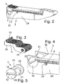
- FIG. 1 shows a head part of an embodiment of a stripping tool 1 with two knife holders 2,3, which are removably mounted on a pull rod 11 at its right end.
- the knife holders 2, 3 are pulled parallel to the longitudinal axis of the knife holder 2.3 towards the tool center during the operation of the stripping tool 1 in order to remove the insulating layer of a conductor inserted in the stripping tool 1 from the conductor.
- the knife holders 2, 3 are arranged in a pliers mouth formed by two clamping jaws, wherein only the lower clamping jaw 10 can be seen in the figure.
- a series of knife blades 4, 5 arranged with the knife holders 2, 3 projecting cutting edges 13 side by side, which are rotatably mounted on the knife holders 2, 3.
- knife pads 6.7 Above or below the blade blades 4, 5 preferably provided in the tool mouth facing the end of the blade holder 2.3.
- the knife pads 6, 7 are rotatably mounted in the stripping tool 1. Preference is given to housing in the knife holders 2, 3, but it is also conceivable to mount the knife pads 2, 3 in the clamping jaws 10 forming the tool jaw.
- FIGS. 2 to 5 show an embodiment of such a knife holder again in detail.
- FIG. 3 shows a detailed view of the blade blades 4, 5. These are formed at one end with a bore 14, which in the installed state, as in Fig. 2 to recognize, correspond with holes 25 in the side surfaces 24 of the knife holder and through which a pin is inserted 8.9, which causes a rotary mounting of the knife blades 4, 5 in the knife holder 2, 3 about the pin longitudinal axis.
- the knife blades 4, 5 have in the longitudinal axis direction of the spatial requirements in the knife holder 2, 3 corresponding contour. A portion 26 of this contour, which with its lower edge (in FIG. 3 ) is supported on the knife pad, is flat.
- FIG. 4 shows the part of an embodiment of a knife holder 3, in which the knife blades 5 and the knife pad 7 are used.
- the knife pad 7 is located at the front end of the knife holder 3 in a transverse to the longitudinal axis of the knife holder 3 formed bore 15.
- This bore 15 is the end face 27 (see FIGS. 6 and 7 ) towards and to the other knife holder opposite surface 28, from which the cutting edges 13 of the blade blades 5 protrude open.
- the side walls 24 of the knife holder thus form a guide for the knife pad 7, in which the knife pad 7 is rotatable.
- FIG. 5 shows a detailed view of the knife pad 7.
- This is cylindrical in shape in the basic form.
- a slot 12 is formed with which the knife pad can be brought under the help of for example a screwdriver in the desired position in knife holder.
- the jacket sections adjoining the end face 29 of the knife pad 7 serve as guide surfaces 18, 19, which are guided in the inner sides 20, 21 of the bore 15.
- the knife pad 7 is rotatably mounted in the knife holder 3.
- the remaining part of the jacket of the knife pad 7 serves as a support for the knife blades 5.
- the jacket surface of the knife pad 7 is designed such that it has differently contoured sections 16, 17.
- a part of the lateral surface of the knife pad is formed as a plane 16 to strip conductors with rectangular cross-sections well, another part of the lateral surface 17 of the knife pad 7 is concave, thereby creating a contour of the cutting profile 23 of the blade blades 5, the corresponds to the contour of a cross-sectionally round conductor.
- angular contours for processing for example, triangular or polygonal conductor cross sections.
- FIGS. 6 to 9 show examples of the position of a knife pad 7 in a knife holder 3 and thereby caused cutting profiles 22, 23 of the knife pad 7 in the knife holder.
- FIG. 6 shows a straight cutting profile 22, which is best suited for stripping conductors with a rectangular cross-section.
- the knife pad 7 is set so that it supports the knife blades 5 with its flat lateral surface.
- FIG. 8 shows a curvy cutting profile 23 of the cutting edges 13 of the blade blades 5, that by an in FIG. 9 shown adjustment of the knife pad is effected.
- the knife cushion is aligned so that it supports the knife blades with a concave shaped lateral surface.
Landscapes
- Knives (AREA)
- Removal Of Insulation Or Armoring From Wires Or Cables (AREA)
- Harvesting Machines For Specific Crops (AREA)
Priority Applications (1)
| Application Number | Priority Date | Filing Date | Title |
|---|---|---|---|
| PL08167599T PL2073333T3 (pl) | 2007-12-21 | 2008-10-27 | Narzędzie do usuwania izolacji |
Applications Claiming Priority (1)
| Application Number | Priority Date | Filing Date | Title |
|---|---|---|---|
| DE202007017867U DE202007017867U1 (de) | 2007-12-21 | 2007-12-21 | Abisolierwerkzeug |
Publications (2)
| Publication Number | Publication Date |
|---|---|
| EP2073333A1 EP2073333A1 (de) | 2009-06-24 |
| EP2073333B1 true EP2073333B1 (de) | 2013-12-04 |
Family
ID=40445757
Family Applications (1)
| Application Number | Title | Priority Date | Filing Date |
|---|---|---|---|
| EP08167599.3A Not-in-force EP2073333B1 (de) | 2007-12-21 | 2008-10-27 | Abisolierwerkzeug |
Country Status (8)
| Country | Link |
|---|---|
| US (1) | US7891273B2 (pl) |
| EP (1) | EP2073333B1 (pl) |
| CN (1) | CN101471549B (pl) |
| DE (1) | DE202007017867U1 (pl) |
| ES (1) | ES2450051T3 (pl) |
| HR (1) | HRP20140104T1 (pl) |
| PL (1) | PL2073333T3 (pl) |
| PT (1) | PT2073333E (pl) |
Families Citing this family (2)
| Publication number | Priority date | Publication date | Assignee | Title |
|---|---|---|---|---|
| CN107294010B (zh) * | 2017-07-18 | 2022-08-02 | 国网河北省电力公司衡水供电分公司 | 绝缘导线剥线器及使用方法 |
| DE102020133953B3 (de) * | 2020-12-17 | 2022-02-17 | Weidmüller Interface GmbH & Co. KG | Abisoliereinheit eines Presswerkzeugs, Presswerkzeug und Verfahren zur Montage einer Einstelleinheit |
Family Cites Families (11)
| Publication number | Priority date | Publication date | Assignee | Title |
|---|---|---|---|---|
| DE1640632A1 (de) * | 1966-07-15 | 1970-03-26 | Walter Kauf | Schiebe-Messer |
| DE1665296B2 (de) * | 1967-03-02 | 1976-05-06 | Abisolierzange | |
| FR96295E (fr) * | 1967-11-04 | 1972-06-16 | Bieganski Zdzislaw | Outil pour enlever la gaine d'un fil métallique gainé. |
| US3703840A (en) * | 1971-06-21 | 1972-11-28 | Walter Kauf | Wire stripper |
| US4197768A (en) * | 1978-06-16 | 1980-04-15 | C. A. Weidmuller K.G. | Device for stripping the sheathing from the ends of insulated electrical conductors |
| DE2827587C3 (de) * | 1978-06-23 | 1980-12-18 | C. A. Weidmueller Kg, 4930 Detmold | Abisolierzange zum Abstreifen des Mantels von einem isolierten elektrischen Leiter |
| DE4420050C1 (de) * | 1994-06-08 | 1995-08-24 | Weidmueller Interface | Abisoliervorrichtung |
| US6089125A (en) * | 1999-08-27 | 2000-07-18 | Cheng; Yin-Ho | Combination wire stripper |
| CN2414534Y (zh) * | 2000-03-20 | 2001-01-10 | 孙立 | 手动可调式剥缆器 |
| CN2514530Y (zh) * | 2001-09-06 | 2002-10-02 | 颜安庭 | 缆线钳 |
| DE20310377U1 (de) * | 2003-07-05 | 2004-11-18 | Weidmüller Interface Gmbh & Co. | Zange mit einer Abisolierstation |
-
2007
- 2007-12-21 DE DE202007017867U patent/DE202007017867U1/de not_active Expired - Lifetime
-
2008
- 2008-10-27 ES ES08167599.3T patent/ES2450051T3/es active Active
- 2008-10-27 PT PT81675993T patent/PT2073333E/pt unknown
- 2008-10-27 PL PL08167599T patent/PL2073333T3/pl unknown
- 2008-10-27 EP EP08167599.3A patent/EP2073333B1/de not_active Not-in-force
- 2008-12-12 US US12/316,487 patent/US7891273B2/en not_active Expired - Fee Related
- 2008-12-19 CN CN2008101863968A patent/CN101471549B/zh not_active Expired - Fee Related
-
2014
- 2014-02-05 HR HRP20140104AT patent/HRP20140104T1/hr unknown
Also Published As
| Publication number | Publication date |
|---|---|
| DE202007017867U1 (de) | 2009-04-23 |
| CN101471549A (zh) | 2009-07-01 |
| ES2450051T3 (es) | 2014-03-21 |
| US20090158900A1 (en) | 2009-06-25 |
| CN101471549B (zh) | 2012-12-19 |
| PT2073333E (pt) | 2014-02-20 |
| PL2073333T3 (pl) | 2014-05-30 |
| US7891273B2 (en) | 2011-02-22 |
| HRP20140104T1 (hr) | 2014-03-14 |
| EP2073333A1 (de) | 2009-06-24 |
Similar Documents
| Publication | Publication Date | Title |
|---|---|---|
| EP4059124B1 (de) | Vorrichtung zum umformen eines in einem statorkern angeordneten leiterstücks sowie ein entsprechendes verfahren | |
| DE2642008C3 (de) | Handzange zum Abisolieren von Leiterenden | |
| EP2081266B1 (de) | Messereinsatz | |
| EP1560310B1 (de) | Abisolierzange | |
| DE2018901C3 (de) | Werkzeug zum Andrücken eines im Querschnitt im wesentlichen Uförmigen elektrischen Verbinders an einen Leiter | |
| DE29825182U1 (de) | Vorrichtung zum Entfernen von Ausbrechteilen aus einem Werkstoffbogen o.dgl. | |
| EP2073333B1 (de) | Abisolierwerkzeug | |
| DE3030610A1 (de) | Werkzeug zum abisolieren eines isolierten elektrischen leiters | |
| WO2018130517A1 (de) | Abisolierzange | |
| DE10214758B4 (de) | Vorrichtung zum Schneiden von Bodenbelägen | |
| DE1046133B (de) | Zange zum Abisolieren von elektrischen Leitungen | |
| DE3406813C2 (pl) | ||
| EP0390760A2 (de) | Gerät zum Anbringen von Kontakten an elektrische Leiter | |
| DE102020133953B3 (de) | Abisoliereinheit eines Presswerkzeugs, Presswerkzeug und Verfahren zur Montage einer Einstelleinheit | |
| DE29906890U1 (de) | Zange | |
| DE10325378A1 (de) | Trimmer zum Beschneiden eines Buches und Beschnittmesser | |
| DE914454C (de) | Vorrichtung zur gleitbaren Befestigung von Werkzeug- und Maschinenteilen | |
| DE202004015416U1 (de) | Bodenführung für ein seitlich verschiebbares Trennelement | |
| DE2505739A1 (de) | Zange, insbesondere abisolierzange | |
| DE19837316A1 (de) | Vorrichtung zum Entfernen von Ausbrechteilen aus einem Werkstoffbogen o. dgl. | |
| DE10038579A1 (de) | Klingenhaltevorrichtung | |
| DE2415966C3 (de) | Mikrotommesserhalter | |
| DE19515880C1 (de) | Vorrichtung zum Entfernen des Mantels von ummantelten Leitern oder Kabeln | |
| DE2004478B2 (de) | Vorrichtung zur Aufnahme von Werkzeugen | |
| DE7504141U (de) | Zange, insbesondere abisolierzange |
Legal Events
| Date | Code | Title | Description |
|---|---|---|---|
| PUAI | Public reference made under article 153(3) epc to a published international application that has entered the european phase |
Free format text: ORIGINAL CODE: 0009012 |
|
| AK | Designated contracting states |
Kind code of ref document: A1 Designated state(s): AT BE BG CH CY CZ DE DK EE ES FI FR GB GR HR HU IE IS IT LI LT LU LV MC MT NL NO PL PT RO SE SI SK TR |
|
| AX | Request for extension of the european patent |
Extension state: AL BA MK RS |
|
| 17P | Request for examination filed |
Effective date: 20090807 |
|
| AKX | Designation fees paid |
Designated state(s): AT BE BG CH CY CZ DE DK EE ES FI FR GB GR HR HU IE IS IT LI LT LU LV MC MT NL NO PL PT RO SE SI SK TR |
|
| 17Q | First examination report despatched |
Effective date: 20130405 |
|
| GRAP | Despatch of communication of intention to grant a patent |
Free format text: ORIGINAL CODE: EPIDOSNIGR1 |
|
| INTG | Intention to grant announced |
Effective date: 20130918 |
|
| RIN1 | Information on inventor provided before grant (corrected) |
Inventor name: HETLAND, DETLEV Inventor name: HANNING, GUENTHER Inventor name: KOESTER, THOMAS Inventor name: STORM, SIEGFRIED Inventor name: WEDLER, ANDREAS Inventor name: HEGGEMANN, CHRISTIAN |
|
| GRAS | Grant fee paid |
Free format text: ORIGINAL CODE: EPIDOSNIGR3 |
|
| GRAA | (expected) grant |
Free format text: ORIGINAL CODE: 0009210 |
|
| AK | Designated contracting states |
Kind code of ref document: B1 Designated state(s): AT BE BG CH CY CZ DE DK EE ES FI FR GB GR HR HU IE IS IT LI LT LU LV MC MT NL NO PL PT RO SE SI SK TR |
|
| REG | Reference to a national code |
Ref country code: GB Ref legal event code: FG4D Free format text: NOT ENGLISH |
|
| REG | Reference to a national code |
Ref country code: CH Ref legal event code: EP |
|
| REG | Reference to a national code |
Ref country code: IE Ref legal event code: FG4D Free format text: LANGUAGE OF EP DOCUMENT: GERMAN Ref country code: AT Ref legal event code: REF Ref document number: 643859 Country of ref document: AT Kind code of ref document: T Effective date: 20140115 |
|
| REG | Reference to a national code |
Ref country code: CH Ref legal event code: NV Representative=s name: ISLER AND PEDRAZZINI AG, CH |
|
| REG | Reference to a national code |
Ref country code: HR Ref legal event code: TUEP Ref document number: P20140104 Country of ref document: HR |
|
| REG | Reference to a national code |
Ref country code: DE Ref legal event code: R096 Ref document number: 502008011024 Country of ref document: DE Effective date: 20140206 |
|
| REG | Reference to a national code |
Ref country code: NL Ref legal event code: T3 |
|
| REG | Reference to a national code |
Ref country code: PT Ref legal event code: SC4A Free format text: AVAILABILITY OF NATIONAL TRANSLATION Effective date: 20140210 |
|
| REG | Reference to a national code |
Ref country code: RO Ref legal event code: EPE |
|
| REG | Reference to a national code |
Ref country code: SE Ref legal event code: TRGR |
|
| REG | Reference to a national code |
Ref country code: HR Ref legal event code: T1PR Ref document number: P20140104 Country of ref document: HR |
|
| REG | Reference to a national code |
Ref country code: ES Ref legal event code: FG2A Ref document number: 2450051 Country of ref document: ES Kind code of ref document: T3 Effective date: 20140321 |
|
| REG | Reference to a national code |
Ref country code: NO Ref legal event code: T2 Effective date: 20131204 |
|
| PG25 | Lapsed in a contracting state [announced via postgrant information from national office to epo] |
Ref country code: FI Free format text: LAPSE BECAUSE OF FAILURE TO SUBMIT A TRANSLATION OF THE DESCRIPTION OR TO PAY THE FEE WITHIN THE PRESCRIBED TIME-LIMIT Effective date: 20131204 Ref country code: LT Free format text: LAPSE BECAUSE OF FAILURE TO SUBMIT A TRANSLATION OF THE DESCRIPTION OR TO PAY THE FEE WITHIN THE PRESCRIBED TIME-LIMIT Effective date: 20131204 |
|
| REG | Reference to a national code |
Ref country code: LT Ref legal event code: MG4D |
|
| PG25 | Lapsed in a contracting state [announced via postgrant information from national office to epo] |
Ref country code: CY Free format text: LAPSE BECAUSE OF FAILURE TO SUBMIT A TRANSLATION OF THE DESCRIPTION OR TO PAY THE FEE WITHIN THE PRESCRIBED TIME-LIMIT Effective date: 20131204 Ref country code: LV Free format text: LAPSE BECAUSE OF FAILURE TO SUBMIT A TRANSLATION OF THE DESCRIPTION OR TO PAY THE FEE WITHIN THE PRESCRIBED TIME-LIMIT Effective date: 20131204 |
|
| REG | Reference to a national code |
Ref country code: PL Ref legal event code: T3 |
|
| PG25 | Lapsed in a contracting state [announced via postgrant information from national office to epo] |
Ref country code: IS Free format text: LAPSE BECAUSE OF FAILURE TO SUBMIT A TRANSLATION OF THE DESCRIPTION OR TO PAY THE FEE WITHIN THE PRESCRIBED TIME-LIMIT Effective date: 20140404 Ref country code: EE Free format text: LAPSE BECAUSE OF FAILURE TO SUBMIT A TRANSLATION OF THE DESCRIPTION OR TO PAY THE FEE WITHIN THE PRESCRIBED TIME-LIMIT Effective date: 20131204 |
|
| PG25 | Lapsed in a contracting state [announced via postgrant information from national office to epo] |
Ref country code: SK Free format text: LAPSE BECAUSE OF FAILURE TO SUBMIT A TRANSLATION OF THE DESCRIPTION OR TO PAY THE FEE WITHIN THE PRESCRIBED TIME-LIMIT Effective date: 20131204 |
|
| REG | Reference to a national code |
Ref country code: DE Ref legal event code: R097 Ref document number: 502008011024 Country of ref document: DE |
|
| REG | Reference to a national code |
Ref country code: HU Ref legal event code: AG4A Ref document number: E020480 Country of ref document: HU |
|
| PLBE | No opposition filed within time limit |
Free format text: ORIGINAL CODE: 0009261 |
|
| STAA | Information on the status of an ep patent application or granted ep patent |
Free format text: STATUS: NO OPPOSITION FILED WITHIN TIME LIMIT |
|
| PG25 | Lapsed in a contracting state [announced via postgrant information from national office to epo] |
Ref country code: DK Free format text: LAPSE BECAUSE OF FAILURE TO SUBMIT A TRANSLATION OF THE DESCRIPTION OR TO PAY THE FEE WITHIN THE PRESCRIBED TIME-LIMIT Effective date: 20131204 |
|
| 26N | No opposition filed |
Effective date: 20140905 |
|
| REG | Reference to a national code |
Ref country code: DE Ref legal event code: R097 Ref document number: 502008011024 Country of ref document: DE Effective date: 20140905 |
|
| PG25 | Lapsed in a contracting state [announced via postgrant information from national office to epo] |
Ref country code: SI Free format text: LAPSE BECAUSE OF FAILURE TO SUBMIT A TRANSLATION OF THE DESCRIPTION OR TO PAY THE FEE WITHIN THE PRESCRIBED TIME-LIMIT Effective date: 20131204 |
|
| PG25 | Lapsed in a contracting state [announced via postgrant information from national office to epo] |
Ref country code: LU Free format text: LAPSE BECAUSE OF FAILURE TO SUBMIT A TRANSLATION OF THE DESCRIPTION OR TO PAY THE FEE WITHIN THE PRESCRIBED TIME-LIMIT Effective date: 20141027 Ref country code: MC Free format text: LAPSE BECAUSE OF FAILURE TO SUBMIT A TRANSLATION OF THE DESCRIPTION OR TO PAY THE FEE WITHIN THE PRESCRIBED TIME-LIMIT Effective date: 20131204 |
|
| PG25 | Lapsed in a contracting state [announced via postgrant information from national office to epo] |
Ref country code: BE Free format text: LAPSE BECAUSE OF NON-PAYMENT OF DUE FEES Effective date: 20141031 |
|
| REG | Reference to a national code |
Ref country code: FR Ref legal event code: PLFP Year of fee payment: 8 |
|
| PG25 | Lapsed in a contracting state [announced via postgrant information from national office to epo] |
Ref country code: BG Free format text: LAPSE BECAUSE OF FAILURE TO SUBMIT A TRANSLATION OF THE DESCRIPTION OR TO PAY THE FEE WITHIN THE PRESCRIBED TIME-LIMIT Effective date: 20131204 |
|
| PG25 | Lapsed in a contracting state [announced via postgrant information from national office to epo] |
Ref country code: GR Free format text: LAPSE BECAUSE OF FAILURE TO SUBMIT A TRANSLATION OF THE DESCRIPTION OR TO PAY THE FEE WITHIN THE PRESCRIBED TIME-LIMIT Effective date: 20140305 |
|
| PG25 | Lapsed in a contracting state [announced via postgrant information from national office to epo] |
Ref country code: MT Free format text: LAPSE BECAUSE OF FAILURE TO SUBMIT A TRANSLATION OF THE DESCRIPTION OR TO PAY THE FEE WITHIN THE PRESCRIBED TIME-LIMIT Effective date: 20131204 |
|
| REG | Reference to a national code |
Ref country code: FR Ref legal event code: PLFP Year of fee payment: 9 |
|
| REG | Reference to a national code |
Ref country code: HR Ref legal event code: ODRP Ref document number: P20140104 Country of ref document: HR Payment date: 20171006 Year of fee payment: 10 |
|
| REG | Reference to a national code |
Ref country code: FR Ref legal event code: PLFP Year of fee payment: 10 |
|
| PGFP | Annual fee paid to national office [announced via postgrant information from national office to epo] |
Ref country code: RO Payment date: 20170926 Year of fee payment: 10 |
|
| PGFP | Annual fee paid to national office [announced via postgrant information from national office to epo] |
Ref country code: PL Payment date: 20170925 Year of fee payment: 10 |
|
| PGFP | Annual fee paid to national office [announced via postgrant information from national office to epo] |
Ref country code: FR Payment date: 20171024 Year of fee payment: 10 Ref country code: NO Payment date: 20171026 Year of fee payment: 10 Ref country code: CZ Payment date: 20171026 Year of fee payment: 10 Ref country code: DE Payment date: 20171019 Year of fee payment: 10 Ref country code: HU Payment date: 20171016 Year of fee payment: 10 Ref country code: TR Payment date: 20171026 Year of fee payment: 10 |
|
| PGFP | Annual fee paid to national office [announced via postgrant information from national office to epo] |
Ref country code: GB Payment date: 20171019 Year of fee payment: 10 Ref country code: NL Payment date: 20171019 Year of fee payment: 10 Ref country code: IT Payment date: 20171023 Year of fee payment: 10 Ref country code: HR Payment date: 20171006 Year of fee payment: 10 Ref country code: ES Payment date: 20171121 Year of fee payment: 10 Ref country code: AT Payment date: 20171020 Year of fee payment: 10 Ref country code: IE Payment date: 20171025 Year of fee payment: 10 Ref country code: CH Payment date: 20171019 Year of fee payment: 10 Ref country code: PT Payment date: 20171023 Year of fee payment: 10 Ref country code: SE Payment date: 20171019 Year of fee payment: 10 |
|
| REG | Reference to a national code |
Ref country code: DE Ref legal event code: R119 Ref document number: 502008011024 Country of ref document: DE |
|
| REG | Reference to a national code |
Ref country code: HR Ref legal event code: PBON Ref document number: P20140104 Country of ref document: HR Effective date: 20181027 |
|
| REG | Reference to a national code |
Ref country code: NO Ref legal event code: MMEP |
|
| REG | Reference to a national code |
Ref country code: SE Ref legal event code: EUG |
|
| REG | Reference to a national code |
Ref country code: CH Ref legal event code: PL |
|
| REG | Reference to a national code |
Ref country code: NL Ref legal event code: MM Effective date: 20181101 |
|
| REG | Reference to a national code |
Ref country code: AT Ref legal event code: MM01 Ref document number: 643859 Country of ref document: AT Kind code of ref document: T Effective date: 20181027 |
|
| GBPC | Gb: european patent ceased through non-payment of renewal fee |
Effective date: 20181027 |
|
| REG | Reference to a national code |
Ref country code: IE Ref legal event code: MM4A |
|
| PG25 | Lapsed in a contracting state [announced via postgrant information from national office to epo] |
Ref country code: PT Free format text: LAPSE BECAUSE OF NON-PAYMENT OF DUE FEES Effective date: 20190429 Ref country code: NO Free format text: LAPSE BECAUSE OF NON-PAYMENT OF DUE FEES Effective date: 20181031 Ref country code: CZ Free format text: LAPSE BECAUSE OF NON-PAYMENT OF DUE FEES Effective date: 20181027 Ref country code: NL Free format text: LAPSE BECAUSE OF NON-PAYMENT OF DUE FEES Effective date: 20181101 Ref country code: DE Free format text: LAPSE BECAUSE OF NON-PAYMENT OF DUE FEES Effective date: 20190501 Ref country code: SE Free format text: LAPSE BECAUSE OF NON-PAYMENT OF DUE FEES Effective date: 20181028 |
|
| PG25 | Lapsed in a contracting state [announced via postgrant information from national office to epo] |
Ref country code: HU Free format text: LAPSE BECAUSE OF NON-PAYMENT OF DUE FEES Effective date: 20181028 Ref country code: CH Free format text: LAPSE BECAUSE OF NON-PAYMENT OF DUE FEES Effective date: 20181031 Ref country code: LI Free format text: LAPSE BECAUSE OF NON-PAYMENT OF DUE FEES Effective date: 20181031 Ref country code: HR Free format text: LAPSE BECAUSE OF NON-PAYMENT OF DUE FEES Effective date: 20181027 Ref country code: FR Free format text: LAPSE BECAUSE OF NON-PAYMENT OF DUE FEES Effective date: 20181031 Ref country code: RO Free format text: LAPSE BECAUSE OF NON-PAYMENT OF DUE FEES Effective date: 20181027 |
|
| PG25 | Lapsed in a contracting state [announced via postgrant information from national office to epo] |
Ref country code: AT Free format text: LAPSE BECAUSE OF NON-PAYMENT OF DUE FEES Effective date: 20181027 Ref country code: GB Free format text: LAPSE BECAUSE OF NON-PAYMENT OF DUE FEES Effective date: 20181027 Ref country code: IT Free format text: LAPSE BECAUSE OF NON-PAYMENT OF DUE FEES Effective date: 20181027 Ref country code: IE Free format text: LAPSE BECAUSE OF NON-PAYMENT OF DUE FEES Effective date: 20181027 |
|
| REG | Reference to a national code |
Ref country code: ES Ref legal event code: FD2A Effective date: 20191203 |
|
| PG25 | Lapsed in a contracting state [announced via postgrant information from national office to epo] |
Ref country code: ES Free format text: LAPSE BECAUSE OF NON-PAYMENT OF DUE FEES Effective date: 20181028 Ref country code: PL Free format text: LAPSE BECAUSE OF NON-PAYMENT OF DUE FEES Effective date: 20181027 |
|
| PG25 | Lapsed in a contracting state [announced via postgrant information from national office to epo] |
Ref country code: TR Free format text: LAPSE BECAUSE OF NON-PAYMENT OF DUE FEES Effective date: 20181027 |