EP2073209B1 - Cartouche à disque - Google Patents
Cartouche à disque Download PDFInfo
- Publication number
- EP2073209B1 EP2073209B1 EP07829622A EP07829622A EP2073209B1 EP 2073209 B1 EP2073209 B1 EP 2073209B1 EP 07829622 A EP07829622 A EP 07829622A EP 07829622 A EP07829622 A EP 07829622A EP 2073209 B1 EP2073209 B1 EP 2073209B1
- Authority
- EP
- European Patent Office
- Prior art keywords
- disk
- portions
- supporting base
- locking lever
- base member
- Prior art date
- Legal status (The legal status is an assumption and is not a legal conclusion. Google has not performed a legal analysis and makes no representation as to the accuracy of the status listed.)
- Not-in-force
Links
- 238000003780 insertion Methods 0.000 claims description 30
- 230000037431 insertion Effects 0.000 claims description 30
- 238000003860 storage Methods 0.000 claims description 6
- 239000013013 elastic material Substances 0.000 claims description 2
- 238000000034 method Methods 0.000 description 48
- 238000004519 manufacturing process Methods 0.000 description 29
- 210000000078 claw Anatomy 0.000 description 26
- 238000011161 development Methods 0.000 description 8
- 238000012360 testing method Methods 0.000 description 7
- 230000003287 optical effect Effects 0.000 description 6
- 238000005520 cutting process Methods 0.000 description 5
- 239000000428 dust Substances 0.000 description 4
- 238000003672 processing method Methods 0.000 description 4
- 238000013500 data storage Methods 0.000 description 3
- 230000005489 elastic deformation Effects 0.000 description 3
- 230000005389 magnetism Effects 0.000 description 2
- 239000000463 material Substances 0.000 description 2
- 239000002245 particle Substances 0.000 description 2
- 230000003014 reinforcing effect Effects 0.000 description 2
- 230000001419 dependent effect Effects 0.000 description 1
- 238000000151 deposition Methods 0.000 description 1
- 230000000994 depressogenic effect Effects 0.000 description 1
- 230000000694 effects Effects 0.000 description 1
- 230000005484 gravity Effects 0.000 description 1
- 238000005304 joining Methods 0.000 description 1
- 238000003754 machining Methods 0.000 description 1
- 230000001681 protective effect Effects 0.000 description 1
- 230000001105 regulatory effect Effects 0.000 description 1
- 239000011347 resin Substances 0.000 description 1
- 229920005989 resin Polymers 0.000 description 1
Images


Classifications
-
- G—PHYSICS
- G11—INFORMATION STORAGE
- G11B—INFORMATION STORAGE BASED ON RELATIVE MOVEMENT BETWEEN RECORD CARRIER AND TRANSDUCER
- G11B23/00—Record carriers not specific to the method of recording or reproducing; Accessories, e.g. containers, specially adapted for co-operation with the recording or reproducing apparatus ; Intermediate mediums; Apparatus or processes specially adapted for their manufacture
- G11B23/02—Containers; Storing means both adapted to cooperate with the recording or reproducing means
- G11B23/03—Containers for flat record carriers
- G11B23/0301—Details
- G11B23/0308—Shutters
-
- G—PHYSICS
- G11—INFORMATION STORAGE
- G11B—INFORMATION STORAGE BASED ON RELATIVE MOVEMENT BETWEEN RECORD CARRIER AND TRANSDUCER
- G11B17/00—Guiding record carriers not specifically of filamentary or web form, or of supports therefor
- G11B17/02—Details
- G11B17/04—Feeding or guiding single record carrier to or from transducer unit
- G11B17/041—Feeding or guiding single record carrier to or from transducer unit specially adapted for discs contained within cartridges
- G11B17/043—Direct insertion, i.e. without external loading means
Definitions
- the present invention relates to a disk cartridge for housing a disklike data storage medium such as an optical disk or a magnetic disk.
- DVD-RAMs, MOs and other rewritable media are housed in a protective casing such as the one disclosed in Patent Document No. 1 in order to protect the data stored there.
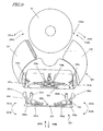
- FIG. 29 is a perspective view schematically illustrating the disk cartridge that is disclosed in Patent Document No. 1.
- the disk cartridge 100 includes a supporting base member 101 that houses a disk 10, which is a read-only or rewritable data storage medium, and that forms the outer shell of the disk cartridge 100.
- the supporting base member 101 consists of an upper housing 101a and a lower housing 101b, which are joined together to store the disk 10 inside.
- the supporting base member 101 has a window 101w to allow some means for rotating the disk 10 (such as a spindle motor) and read/write means such as an optical head to enter the supporting base member 101 and access the disk 10.
- the window 101w has been cut through the principal surfaces of the upper and lower housings 101a and 101b and the disk 10 housed in the supporting base member 101 is exposed through the window 101w.
- the disk cartridge 100 includes a cartridge shutter 103 that has been folded in a C-shape to close the window 101w on the upper and lower surfaces of the supporting base member 101 and to sandwich the supporting base member 101 and protect the data side of the disk 10 to be exposed inside the window 101w.
- the cartridge shutter 103 can move parallel in the direction indicated by the arrow P in FIG. 29 and is biased by a spring so as to keep the window 101w closed.
- this disk cartridge 100 is designed so as not to expose the disk 10 inside the window 101w unless some external force is applied to the cartridge shutter 103.
- the supporting base member 101 further includes a bridge portion 104 that bridges an outer side of the window 101w.
- the bridge portion 104 not only maintains the rigidity of the supporting base member 101 but also guides the cartridge shutter 103 in the direction indicated by the arrow P.
- the disk cartridge 100 prevents dust from entering the disk cartridge 100 being carried through the window 101w and also prevents the user from leaving a fingerprint on the disk 10.
- the disk needs to be clamped and rotated by the spindle motor and the optical head needs to access the disk 10.
- the disk cartridge 100 being inserted into the disk drive goes in the direction indicated by the arrow Q
- the notched portion 103a of the cartridge shutter 103 gets engaged with the protrusion 104a of a shutter opener 104 and the shutter opener 104 is turned around the center of rotation 104b in the direction indicated by the arrow R, thereby sliding the cartridge shutter 103 in the direction indicated by the arrow 30 P as shown in FIG. 30 .
- the cartridge shutter 103 can be opened and the disk 10 can be exposed through the window 101w.
- the cartridge shutter 103 has a C-folded shape. For that reason, unless a high-precision machining process is carried out, it is difficult to mass-produce the cartridge shutters 103 with little shape error. Thus, the manufacturing costs should go up to get that done. On top of that, although there has been a growing trend in recent years toward products with a reduced thickness, it is difficult to reduce the thickness of the cartridge shutter 103 with such a structure.
- the cartridge shutter 103 should have a fragile structure. That is why if the disk cartridge 100 were subjected to any impact or trodden by mistake, devastating damage could be done to the information storage layer of the disk.
- the bridge portion 104 needs to be arranged as a guide for opening and closing the cartridge shutter 103 on either the upper housing 101a or the lower housing 101b so as to bridge the window 101w. That is why if the optical head to access the disk 10 were thick in the height direction, then the head would be obstructed by the bridge portion 104 and unable to access the disk 10.
- the cartridge shutter 103 performs its opening and closing operations just linearly. That is why if the outer dimensions of the disk cartridge 103 are reduced to house a small disk there, then the area of the window 101w will be very small. For that reason, if such a small cartridge should be used in a device of a small size or a disk video camera, the size of the head should also be very small, thus producing a problem in designing such a head.
- a space that would allow the disk cartridge 100 some positioning error in the disk drive should be left inside the supporting base member 101 . That is why the disk 10 can move freely within that space that would allow the positioning error inside the supporting base member 101 without being held by the disk cartridge 100 . As a result, the disk 10 will loosen and rattle inside the supporting base member 101 , thus possibly getting the information storage layer of the disk 10 scratched or producing particles due to a collision between the disk 10 and the inner walls of the supporting member 101 and depositing the particles on the disk 10 .
- the manufacturing process of the disk 10 and the processes of making respective members to form the disk cartridge 100 and assembling those members into the disk cartridge 100 have big differences in manufacturing and processing methods, the type of tests and so on.
- the disk 10 should be inserted while the upper and lower housings 101a and 101b are merged together. That is to say, the disk 10 needs to be inserted during the manufacturing process of the disk cartridge 100. That is why it is impossible to perform the manufacturing process of the disk 10 itself and the assembling process of the disk cartridge 100 itself in two different places totally separately from each other. As a result, the manufacturing costs cannot be cut down, which is a problem.
- the disk cartridge of the present invention has no conventional housing, which defines the profile of the cartridge in the prior art, but includes a pair of disk housing portions that not only defines the profile of the cartridge but also functions as shutters as well.
- the pair of disk housing portions can define a big head access window that does not have the guide portion, which should be arranged in the window of a conventional disk cartridge with a shutter to guide the shutter on the move. Consequently, even a cartridge of a small size can open as big a head access window as a cartridge of a large size.
- the disk cartridge of the present invention since the disk cartridge of the present invention includes a supporting base member that partially overlaps with the pair of disk housing portions, a steady disk cartridge that sufficiently resists a deformation perpendicularly to the disk housed there is realized.
- a locking member which not only controls the angle of the window defined by the disk housing portions but also keeps the disk housing portions in the closed state from rotating, can be inserted after the disk housing portions and the supporting base member, consisting of the supporting base portions, have been assembled together. For that reason, even after the supporting base member has been assembled, the disk housing portions can also be opened wide enough to readily remove the disk from the disk cartridge. That is why after the supporting base member has been assembled, the disk may be inserted, and the assembling process of the disk cartridge can be completed by inserting the locking member through the insertion port of the supporting base member. As a result, the disk manufacturing process and the disk cartridge assembling process can be totally separated from each other. Consequently, a disk cartridge manufacturing process can be carried out with the disk manufacturing process and the disk cartridge assembling process, which have significantly different process and testing methods, performed in two different places, thus increasing the degree of flexibility of the manufacturing process and cutting down the manufacturing costs significantly.
- the disk cartridge of the present invention can prevent the user from inserting the disk cartridge wrong end first, i.e., opposite to the proper inserting direction, into the disk drive. That is to say, it is possible to avoid an unwanted situation where the disk cartridge is inserted wrong end first, the unlocking portions of the disk drive reach the locking/unlocking portions to unlock the locking members that keep the disk housing in the closed state, and the disk housing is opened with the disk side sticking out of the disk drive.
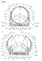
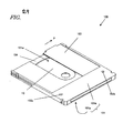
- FIG. 1 shows perspective views illustrating the general appearance of a disk cartridge 201.
- FIG. 1(a) illustrates how the disk cartridge 201 looks when its disk housing 230 is closed
- FIG. 1(b) illustrates how the disk cartridge 201 looks when the disk housing 230 is opened
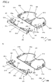
- FIG. 2 shows perspective views illustrating the general appearance of the disk cartridge 201 as viewed from above the lower side thereof.
- FIG. 2(a) illustrates how the disk cartridge 201 looks when its disk housing 230 is closed
- FIG. 2(b) illustrates how the disk cartridge 201 looks when the disk housing 230 is opened.
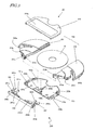
- FIG. 3 is an exploded perspective view illustrating respective members that form the disk cartridge 201.
- the disk cartridge 201 includes first and second disk housing portions 231 and 232, which form the disk housing 230, and a supporting base member 205.
- the supporting base member 205 consists of an upper supporting base portion 210 and a lower supporting base portion 220. By joining these portions together, the first and second disk housing portions 231 and 232 can be partially sandwiched and supported rotatably.
- the disk housing 230 which is partially exposed from the supporting base member 205, and the supporting base member 205 together form the outer shell of the disk cartridge 201.
- the disk housing 230 is composed of the first and second disk housing portions 231 and 232, each of which has a baglike space that defines a gap in the thickness direction of the disk 10 and that is big enough to house a portion of the disk 10.
- the first and second disk housing portions 231 and 232 are merged together with the edges of their baglike openings fitted closely into each other. In this manner, the disk 10 can be housed in its entirety so as not to be exposed at all.
- a substantially fan-shaped window 230w is created by the supporting base member 205 and the disk housing 230 to allow a spindle motor, clamper and other members for rotating the disk 10 to chuck and rotate the disk 10 and also allow a read/write head to enter the disk cartridge 201 and access the disk 10 from outside of the disk cartridge 201.
- the disk housing 230 functions not only as a housing, or an outer shell for the disk cartridge 201, but also as shutters for opening and shutting the window 230w.
- first and second disk housing portions 231 and 232 alone, theoretically speaking.
- some torsional force would be produced to cause significant deformation or damage.
- the disk cartridge 201 includes the supporting base member 205, which overlaps at least partially with the first and second disk housing portions 231 and 232 so as to prevent the first and second disk housing portions 231 and 232 from moving perpendicularly to the disk 10. Then, even if any torsional force were applied to the first and second disk housing portions 231 and 232 , it would be still possible to prevent the first and second disk housing portions 231 and 232 from being deformed at least in the portions that are sandwiched by the supporting base member 205 . As a result, the steadiness of the overall disk cartridge 201 can be increased.
- a locking structure for preventing the first and second disk housing portions 231 and 232 closed from rotating may also be provided.
- the supporting base member 205 stands still even while the disk housing 230 is being opened or closed. That is why when the user inserts the cartridge 201 into a disk drive, the supporting base member 205 can function as a holder portion to be held by the user with his or her hands.
- the upper supporting base portion 210 may have a label affixing depressed portion 210p , to which a piece of label sticker showing the contents of information stored in the disk 10 can be affixed. In this manner, the contents of the information stored in the disk 10 that is housed in the disk cartridge 201 can be shown.
- the supporting base member 205 preferably covers a part of the disk 10 that is closer to the rotating and supporting portion of the first and second disk housing portions 231 and 232 with respect to the center of the disk 10 that is housed in the first and second disk housing portions 231 and 232 in the closed state.
- the lower supporting base portion 220 has positioning holes 225a and 225b to position the disk cartridge 201 on a plane that is parallel to the disk 10 in a disk drive (not shown).
- the lower supporting base portion 220 has notches 220t on both sides thereof. These notches 220t may be used to prevent the user from loading the disk cartridge 201 upside down in a tray loading system or to hold the disk cartridge 201 in a slot loading system, for example.
- the first and second disk housing portions 231 and 232 have pivot holes 231a and 232a, respectively, into which pivots 220a and 220b on the lower supporting base portion 220 are respectively inserted, thereby supporting the first and second disk housing portions 231 and 232 rotatably such that these housing portions 231 and 232 can turn around the pivots 220a and 220b, respectively.
- the first and second disk housing portions 231 and 232 further have engaging portions 231b and 232b that engage and interlock with each other. By interlocking these engaging portions 231b and 232b with each other, the first and second disk housing portions 231 and 232 can turn in mutually opposite directions and synchronously with each other.
- the first and second disk housing portions 231 and 232 have notches 231d and 232d, which can be used to open or close the disk housing 230 externally.
- the disk cartridge 201 further includes a locking unit 253.
- the locking unit 253 is made up of members that are provided separately from the supporting base member 205.
- the locking unit 253 is integrated with the supporting base member 205 by being inserted into the insertion port 205t of the supporting base member 205 and prevents the first and second disk housing portions 231 and 232 in the closed state from rotating.
- the locking unit 253 includes a locking lever supporting portion 250 and first and second locking lever portions 241 and 242.
- the first and second locking lever portions 241 and 242 are secured to the locking lever supporting portion 250 with rotating hinge portions 250a and 250b, respectively, and the locking lever supporting portion 250 and the first and second locking lever portions 241 and 242 have been formed as an integral member.
- the first locking lever portion 241 includes a latching lever portion 241b, an opener/closer 241c and an elastic portion 241d.
- the latching lever portion 241b fits into the catching portion 231c of the first disk housing portion 231 (see FIG. 6 ), thereby preventing the first disk housing portion 231 from turning in the opening direction while the disk housing 230 is closed. If the opener/closer 241c is pressed down externally, the first locking lever portion 241 can be biased so as to turn on the rotating hinge portion 250a. And the elastic portion 241d (see FIG. 5 ) deforms elastically while overcoming the biasing force applied by the opener/closer 241c, thereby producing biasing force in the first locking lever portion 241.
- the second locking lever portion 242 includes a latching lever portion 242b, an opener/closer 242c and an elastic portion 242d.
- the latching lever portion 242b gets engaged with the catching portion 232c of the second disk housing portion 232 (see FIG. 6 ), thereby preventing the second disk housing portion 232 from turning in the opening direction while the disk housing 230 is closed. If the opener/closer 242c is pressed down externally, the second locking lever portion 242 can be biased so as to turn on the rotating hinge portion 250b. And the elastic portion 242d (see FIG. 5 ) deforms elastically while overcoming the biasing force applied by the opener/closer 242c, thereby producing biasing force in the second locking lever portion 242.
- the rotating hinge portions 250a and 250b can function as hinges and the elastic portions 241d and 242d are given elasticity.
- the disk cartridge 201 has unlocking grooves 200a and 200b for operating the first and second locking lever portions 241 and 242 on the right- and left-hand sides thereof.
- the openers/closers 241c and 242c of the first and second locking lever portions 241 and 242 are designed so as to protrude through the openings at the bottom of the unlocking grooves 200a and 200b, respectively, but not to stick out of the outer shell of the disk cartridge 201. That is to say, the protrusion level of the openers/closers 241c and 242c as measured from the bottom of the unlocking grooves 200a and 200b is short of the depth of the unlocking grooves 200a and 200b. That is why normally a person who handles the disk cartridge 201 cannot easily press the openers/closers 241c and 242c with his or her fingers. In this manner, it is possible to prevent the user from unlocking the disk housing 230 intentionally and carelessly.
- FIG. 4 shows perspective views illustrating the structures of the locking unit 253 and the supporting base member 205. Specifically, FIG. 4(a) illustrates the lower supporting base portion 220 and the locking unit 253, while FIG. 4(b) illustrates the upper supporting base portion 210 and the locking unit 253.
- FIG. 5 shows plan views illustrating the structure of the locking unit 253. Specifically, FIG. 5(a) illustrates the position of the locking unit 253 yet to be fitted into the supporting base member 205. FIG. 5(b) illustrates the position of the locking unit 253 that has already been fitted into the supporting base member 205. And FIG. 5(c) illustrates the position of the locking unit 253 while the first and second locking lever portions 241 and 242 are turning.
- the locking lever supporting portion 250 of the locking unit 253 includes a body 250t, a first pair of latching claw portions 251a and 251b, and a second pair of latching claw portions 251c and 251d.
- the body 250t has a substantially rectangular shape corresponding to that of the insertion port 205t of the supporting base member 205.
- the body 250t covers the insertion port 205t fully.
- the body 250t is just a substantially rectangular plate with no reinforcing ribs and is easily deformable elastically.
- the body 250t is deformed elastically to flex the entire locking unit 253.
- the first and second pairs of latching claw portions 251a, 251b, 251c and 251d can get easily engaged with their associated catching portions on the supporting base member 205, thus getting the assembling process done more smoothly.
- the first and second pairs of latching claw portions 251a, 251b, 251c and 251d serve as stoppers when the locking unit 253 is inserted and fitted into the supporting base member 205 in the direction indicated by the arrow 200A .
- the first pair of latching claw portions 251a and 251b is arranged in the vicinity of both ends of the body 250t in the longitudinal direction, while the second pair of latching claw portions 251c and 251d is arranged around the center of the body 250t in the longitudinal direction.
- the locking lever supporting portion 250 further includes positioning hole cover portions 255a and 255b that will cover the positioning holes 225a and 225b of the lower supporting base portion 220 so as to define recesses with the positioning holes 225a and 225b as bottom holes when the locking unit 253 is fitted into the supporting base member 205 . In this manner, it is possible to prevent dust from entering the supporting base member 205 through the positioning holes 225a and 225b .
- the lower supporting base portion 220 has a first pair of catching portions 221a and 221b to engage with the first pair of latching claw portions 251a and 251b of the locking lever supporting portion 250 and a second pair of catching portions 221c and 221d to engage with the second pair of latching claw portions 251c and 251d of the locking lever supporting portion 250 .
- Each of these catching portions has a tapered side to get the locking lever supporting portion 250 inserted easily in the direction indicated by the arrow 200A .
- the lower supporting base portion 220 further has positioning holes 222a and 222b for aligning the lower supporting base portion 220 with the upper supporting base portion 210 and positioning bosses 224a and 224b for positioning the locking unit 253 fitted.
- the upper supporting base portion 210 has a first pair of catching portions 211a and 211b to engage with the first pair of latching claw portions 251a and 251b of the locking lever supporting portion 250 and a second pair of catching portions 211c and 211d to engage with the second pair of latching claw portions 251c and 251d of the locking lever supporting portion 250 as shown in FIG. 4 (b ).
- Each of these catching portions has a tapered side to get the locking lever supporting portion 250 inserted easily in the direction indicated by the arrow 200A.
- the upper supporting base portion 210 further has positioning bosses 212a and 212b to be respectively fitted into the positioning holes 222a and 222b of the lower supporting base portion 220, thereby aligning these two supporting base portions with each other.
- the second pair of catching portions 211c and 211d of the upper supporting base portion 210 and the second pair of catching portions 221c and 221d of the lower supporting base portion 220 form integral parts of ribs around the center of the insertion port 105 in the longitudinal direction thereof. That is why when the upper and lower supporting base portions 210 and 220 are joined and welded or bonded together, not only the ribs on both sides of the supporting base member 205 but also those ribs may be welded or bonded together to join the center portions of the supporting base member 205 together. As a result, even when the locking unit 253 is not fitted yet, the mechanical strength of the supporting base member 205 can also be increased.
- the first and second pairs of latching claw portions 251a, 251b, 251c and 251d of the locking lever supporting portion 250 engage with not only the first and second pairs of catching portions 221a , 221b , 221c and 221d of the lower supporting base portion 220 but also the first and second pairs of catching portions 211a , 211b, 211c and 211d of the upper supporting base portion 210 . Consequently, the locking unit 253 can be firmly held by the supporting base member 205 .
- the first and second locking lever portions 241 and 242 form integral parts of the locking lever supporting portion 250 by way of the rotating hinge portions 250a and 250b , respectively, in the locking unit 253 .
- the first and second locking lever portions 241 and 242 are supported so as to turn substantially on the rotating hinge portions 250a and 250b .
- the elastic portions 241d and 242d are deformed elastically while overcoming the biasing force applied by the opener/closers 241c and 242c , thereby producing biasing force in the first and second locking lever portions 241 and 242 . Due to the elastic deformation at the ends of the rotating hinge portions 250a and 250b and the elastic portions 241d and 241c , some stress is produced in the body of the locking lever supporting portion 250 .
- first pair of latching claw portions 251a and 251b are arranged near the rotating hinge portions 250a and 250b , respectively, and the second pair of latching claw portions 251c and 251d are arranged near the respective ends of the elastic portions 241d and 242d , thereby fitting the body 250t of the locking lever supporting portion 250 into the supporting base member 205 . Consequently, without deforming the body 250t of the locking lever supporting portion 250 due to the stress, the first and second locking lever portions 241 and 242 can rotate on the rotating hinge portions 250a and 250b in the directions indicated by the arrows 241A and 242A , respectively.
- the first and second locking lever portions 241 and 242 can rotate in the directions indicated by the arrows 241B and 242B by utilizing the elastic force of the elastic portions 241d and 242d that have been deformed elastically.
- the first and second locking lever portions 241 and 242 by themselves (i.e., before the locking lever supporting portion 250 is fitted into the supporting base member 205) are tilted by ⁇ 1 and ⁇ 2 degrees in the directions indicated by the arrows 241B and 242B, respectively, compared to the situation where the locking lever supporting portion 250 has been inserted into the supporting base member 205 as shown in FIG. 5(b) .
- FIGS. 6(a) and 6(b) are partial cross-sectional views of the disk cartridge 201 in a situation where the disk housing 230 is closed and a situation where the disk housing 230 is opened, respectively.
- the latching lever portions 241b and 242b of the first and second locking lever portions 241 and 242 get engaged with the catching portions 231c and 232c of the first and second disk housing portions 231 and 232 , thereby stopping the first and second disk housing portions 231 and 232 from turning in the directions indicated by the arrows 231A and 232A , respectively. In this manner, the first and second disk housing portions 231 and 232 are kept from rotating while the disk housing 230 is closed.
- the inner walls of the first and second disk housing portions 231 and 232 have portions (not shown) that either contact with, or are spaced just slightly from, the outer edge of the disk 10 to hold the disk 10 firmly when the disk housing 230 is closed. As a result, while the disk housing 230 is closed, the disk 10 is held firmly and never rattles.
- the first and second locking lever portions 241 and 242 are turned at the same time with a member provided for the disk drive (to be described later), thereby unlocking the disk housing 230 while deforming the elastic portions 241d and 242d elastically.
- the opening/closing members 151 and 152 of the disk drive get engaged with the notches 231d and 232d of the first and second disk housing portions 231 and 232.
- the disk housing 230 comes to have a first opening position as shown in FIG. 6 (b).
- the catching portions 231c and 232c of the first and second disk housing portions 231 and 232 move between the latching lever portions 241b and 242b of the first and second locking lever portions 241 and 242 and the openers/closers 231c and 232c.
- the first and second locking lever portions 241 and 242 go back to the positions shown in FIG. 6(a) when the disk housing 230 is closed. That is why even in the first opening position in which the disk housing 230 is opened, the first and second locking lever portions 241 and 242 cannot turn in the unlocking directions indicated by the arrows 241A and 242B.
- the elastic portions 241d and 242d also recover their original states, it is possible to avoid creep that would be produced if the elastic portions 241d and 242d were kept deformed elastically.
- the inner walls of the first and second disk housing portions 231 and 232 come out of contact with the disk 10.
- the position regulating portions 223a and 223b of the lower supporting base portion 220 and the positioning portion 65 of the disk drive contact with the outer side surface of the disk 10 , thereby positioning the disk 10 with respect to the lower supporting base portion 220 (or the supporting base member 205 ).
- the first and second locking lever portions 241 and 242 limit the rotation of the first and second disk housing portions 231 and 232 in the directions indicated by the arrows 231A and 232A . That is why in the first opening position in which the disk housing 230 is opened, it is possible to prevent the first and second disk housing portions 231 and 232 from rotating so much as to widen the window 230w to the point that the disk 10 drops easily.
- the opening/closing members 151 and 152 of the disk drive turn the first and second disk housing portions 231 and 232 in opposite directions (i.e., in the directions indicated by the arrows 231B and 232B , respectively) compared to the opening operation described above.
- the first and second locking lever portions 241 and 242 contact with the catching portions 231c and 232c of the first and second disk housing portions 231 and 232 turning to rotate in the directions 241A and 242A, respectively.
- the disk housing 230 is fully closed as shown in FIG.
- the first and second locking lever portions 241 and 242 rotate in the directions indicated by the arrows 241B and 242B, respectively, under the elastic force applied by their elastic portions 241d and 242d.
- the latching lever portions 241b and 242b of the first and second locking portions 241 and 242 get engaged with the catching portions 231c and 232c of the first and second disk housing portions 231 and 232, respectively, thereby stopping the disk housing 230 from turning. In this manner, the operation of closing the disk housing 230 can get done.
- the overall cartridge projection area of the disk 10, the disk housing 230 and the supporting base member 205 that is defined perpendicularly to the axis of rotation of the disk 10 is greater as shown in FIG. 6(b) than when the disk housing 230 is closed as shown in FIG. 6(a) .
- the window 230w can have an increased opening area even though the disk cartridge 201 has a reduced overall size, the head can be designed much more flexibly.
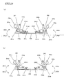
- FIG. 7 shows partial cross-sectional views of the disk cartridge 201 .
- FIG. 7(a) illustrates a situation where only the second locking lever portion 242 has been unlocked by being turned in the direction indicated by the arrow 242A while the first and second disk housing portions 231 and 232 are locked with the first and second locking lever portions 241 and 242 .
- FIG. 7(a) illustrates a situation where only the second locking lever portion 242 has been unlocked by being turned in the direction indicated by the arrow 242A while the first and second disk housing portions 231 and 232 are locked with the first and second locking lever portions 241 and 242 .
- FIG. 7(a) illustrates a situation where only the second locking lever portion 242 has been unlocked by being turned in the direction indicated by the arrow 242A while the first and second disk housing portions 231 and 232 are locked with the first and second locking lever portions 241 and 242 .
- FIG. 7(a) illustrates a situation where only the second locking lever portion 242 has been unlocked
- FIG. 7(b) illustrates a situation where both the first and second locking lever portions 231 and 232 have been unlocked by being turned in the directions indicated by the arrows 241A and 242A , respectively, while the first and second disk housing portions 231 and 232 are locked with the first and second locking lever portions 241 and 242 .
- first and second disk housing portions 231 and 232 are kept from turning in the directions indicated by the arrows 231A and 232A, respectively, by the first and second locking lever portions 241 and 242 as shown in FIG. 7(a) .
- the opener/closer 242c of the second locking lever portion 242 is pressed down externally with a member provided for the disk drive, the second locking lever portion 242 rotates in the direction indicated by the arrow 242A with its elastic portion 242d deformed.
- the latching lever portion 242b of the second locking lever portion 242 disengages itself from the catching portion 232c of the second disk housing portion 232.
- the first and second disk housing portions 231 and 232 are still engaged with each other by their engaging portions 231b and 232b and the first disk housing portion 231 is still kept from turning in the direction indicated by the arrow 231A by the first locking lever portion 241. For that reason, the first and second disk housing portions 231 and 232 still cannot be opened.
- first and second disk housing portions 231 and 232 still could not be opened.
- the openers/closers 241c and 242c of the first and second locking portions 241 and 242 are externally pressed down at the same time in the state shown in FIG. 6(a) , the first and second locking lever portions 241 and 242 rotate in the directions indicated by the arrows 241A and 242A, respectively, with their elastic portions 241d and 242d deformed as shown in FIG. 7(b) .
- the latching lever portions 241b and 242b of the first and second locking lever portions 241 and 242 disengage themselves from the catching portions 231c and 232c of the first and second disk housing portions 231 and 232 and unlocked.
- the first and second disk housing portions 231 and 232 can now rotate in the directions indicated by the arrows 231A and 232A.
- first and second disk housing portions 231 and 232 can be opened.
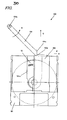
- FIG. 8 is a perspective view illustrating an assembly process in which the disk 10 and the locking lever supporting portion 250 are inserted into the disk cartridge 201 in the second opening position in which the disk housing 230 has been opened wide enough to remove the disk 10 easily.
- the first and second disk housing portions 231 and 232, the upper supporting base portion 210, the lower supporting base portion 220, and the locking unit 253 are provided. These members may be made of resin, for example.
- the pivots 220a and 220b of the lower supporting base portion 220 are inserted into the pivot holes 231a and 232 a of the first and second disk housing portions 231 and 232 and the upper supporting base portion 210 is either welded or bonded with the lower supporting base portion 220 .
- the disk cartridge 201 ' can be assembled as shown in FIG. 8 .
- the locking unit 253 has not been inserted into the disk cartridge 201 ' yet.
- FIG. 9 is a partial cross-sectional view showing one stage of the assembly process of the disk cartridge 201 and illustrating a situation where the disk cartridge 201 ' has been opened to the second opening position.
- the first and second disk housing portions 231 and 232 can rotate more freely than in the first position in the directions indicated by the arrows 231A and 232A to contact with the lower supporting base portion 220 (i.e., the supporting base member 205 ).
- a window 230w ' in the second opening position which is wider than the window 230w in the first opening position, is defined.
- the disk 10 may be moved either in the direction indicated by the arrow 200B to get inserted into the disk cartridge 201 ' or in the direction indicated by the arrow 200A to get ejected out of the disk cartridge 201 '.
- the disk 10 can be inserted into the disk cartridge 201 ' through the window 230w ' as the disk housing 230 has been opened to the second position as shown in FIG. 10 .
- the disk housing 230 will be fully closed and the disk 10 will get housed in the disk housing 230 as shown in FIG. 11 .
- the locking unit 253 has not been inserted into the disk cartridge 201 ' yet, and therefore, the disk housing 230 can be opened or closed freely. If necessary, the disk housing 230 closed may be opened to the second opening position and the disk 10 may be removed.
- the disk drive opens or closes the disk housing 230 with the opening/closing members 151 and 152 of the disk drive fitted into the notches 231d and 232d of the first and second disk housing portions 231 and 232 as shown in FIG. 6 . That is why even the disk cartridge 201 ' in such an - incomplete state can also be loaded into the disk drive and can have its disk housing 230 opened or closed with no problem. Consequently, the disk cartridge 201 ' to which the locking unit 253 has not been inserted yet functions as a disk cartridge, to and from which the disk 10 can be inserted or removed freely.
- Such a disk cartridge 201 ' may be used in a manufacturing or development process step in which the disks 10 need to be changed frequently, e.g., in the process step of testing the disk drive to be loaded with the disk cartridge 201 or during the development of game software.
- the openers/closers 241c and 242c of the first and second locking lever portions 241 and 242 will contact with the inner walls of the lower supporting base portion 220 (or supporting base member 205 ).
- the first and second locking lever portions 241 and 242 are turned in the directions indicated by the arrows 241A and 242A , respectively.
- the body 250t of the locking lever supporting portion 250 is deformed elastically. As a result, the locking unit 253 gets inserted into the supporting base member 205 with the locking lever supporting portion 250 flexed entirely.
- the locking unit 253 being inserted can be deformed significantly in its entirety. As a result, the load to be placed while the locking unit 253 is inserted can be reduced so much that the locking unit 253 can be inserted easily. In other words, the disk cartridge 201 can be assembled more easily.
- the locking unit 253 is flexed in its entirety, the first pair of latching claw portions 251a and 251b of the locking lever supporting portion 250 gets engaged with the supporting base member 205 earlier than the second pair of latching claw portions 251c and 251d thereof. That is to say, since only two of the four latching claw portions get engaged at the same time while the locking lever supporting portion 250 is being inserted, the locking unit 253 can be inserted with reduced force. As a result, the disk cartridge 201 can be assembled more easily.
- the first pair of latching claw portions 251a and 251b gets engaged with the first pair of catching portions 221a and 221b of the lower supporting base portion 220 (and the first pair of catching portions 211a and 211b of the upper supporting base portion 210 ) earlier than the other pair because the locking unit 253 is flexed in its entirety as described above.
- the second pair of latching claw portions 251c and 251de gets engaged with the second pair of catching portions 221c and 221d of the lower supporting base portion 220 (and the first pair of catching portions 211c and 211d of the upper supporting base portion 210 ).
- the locking unit 253 gets fully fitted into the supporting base member 205 as shown in FIG. 13 .
- the first and second latching lever portions 241b and 242b of the first and second locking lever portions 241 and 242 get engaged with the catching portions 231c and 232c of the first and second disk housing portions 231 and 232 , thereby keeping the first and second disk housing portions 231 and 232 from rotating in the directions indicated by the arrows 231A and 232.
- the openers/closers 241c and 242c of the first and second locking lever portions 241 and 242 protrude through the unlocking grooves 200a and 200b on the side surfaces of the supporting base member 205. In this manner, the disk cartridge 201 is completed.
- the first and second locking lever portions 241 and 242 can keep the disk housing 230 in the closed state from rotating.
- the first and second locking lever portions 241 and 242 or the locking lever supporting portion 250 can keep the first and second disk housing portions 231 and 232 from rotating in the directions indicated by the arrows 231A and 232A as shown in FIG. 6(b) , thereby preventing the user from removing the disk 10.
- the first and second disk housing portions 231 and 232 are closed.
- the assembling process may also get done even with the first and second disk housing portions 231 and 232 opened.
- FIG. 14 is a partial cross-sectional view illustrating a situation where the locking unit 253 is inserted with the first and second disk housing portions 231 and 232 opened. As shown in FIG. 14 , if the locking unit 253 is inserted with the first and second disk housing portions 231 and 232 opened, then the openers/closers 241c and 242c of the first and second locking lever portions 241 and 242 contact with the catching portions 231c and 232c of the first and second disk housing portions 231 and 232 , respectively.
- the first and second disk housing portions 231 and 232 being in contact with the openers/closers 241c and 242c of the first and second locking lever portions 241 and 242 rotate in the directions indicated by the arrows 231B and 232B, respectively. That is why even if the locking unit 253 is inserted with the first and second disk housing portions 231 and 232 opened, the first and second disk housing portions 231 and 232 can also be closed and the disk cartridge 201 can be assembled with no problem at all as the locking unit 253 is inserted deeper.
- the disk cartridge 201 can be assembled just as intended with the number of mistakes reduced during the assembling work.
- the disk housing 230 is closed by itself as the locking unit 253 is inserted, the number of assembling process steps can be cut down, too.
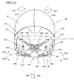
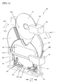
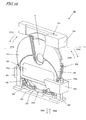
- FIGS. 15 through 17 are perspective views illustrating main elements that form such a machine 300 of assembling the disk cartridge 200.
- FIGS. 15 , 16 and 17 illustrate three different states of the assembling machine 300 while the disk 10 is being inserted, while the locking unit 253 is being inserted, and when the disk cartridge 200 gets assembled, respectively.
- the machine 300 of assembling the disk cartridge 200 includes a cartridge supporting portion 310 for supporting the disk cartridge 201 ' to which the locking unit 253 has not been inserted yet, an assembling base portion 320 for holding and guiding the locking unit 253 , and a disk insertion guide portion 330 that has a port for inserting the disk 10 and that serves as a press member when the locking unit 253 is inserted.
- the assembling base portion 320 further includes assembling guide portions 321 and 322 for guiding the locking unit 253 in the directions indicated by the arrows 300A and 300B.
- the cartridge supporting portion 310 may also be moved in the directions indicated by the arrows 300A and 300B by a robot arm (not shown), for example.
- this assembling machine 300 performs the assembling process.
- the disk cartridge 201 ' is loaded into the cartridge supporting portion 310 and the locking unit 253 is fitted into the assembling base portion 320 .
- the disk cartridge 201 ' is held vertically such that the supporting base member 205 faces down. That is why the first and second disk housing portions 231 and 232 of the disk cartridge 201 ' rotate due to their own weight in the directions indicated by the arrows 231A and 232A , respectively, thereby defining a window 230w ' in the second opening position.
- the disk 10 is inserted through the disk insertion port 335 of the disk insertion guide portion 330. Then, the disk 10 will go down due to its own weight in the direction indicated by the arrow 300A while being guided along the disk insertion port 335 and will get inserted into the disk cartridge 201 ' eventually.
- the cartridge supporting portion 310 If the cartridge supporting portion 310 is moved in the direction indicated by the arrow 300A after the disk 10 has been inserted fully (see FIG. 10 ), then the first and second disk housing portions 231 and 232 will contact with the tapered portions 321a and 322a of the assembling guide portions 321 and 322 , and start to rotate in the directions indicated by the arrows 231B and 232B , respectively, as shown in FIG. 16 . Meanwhile, as the cartridge supporting portion 310 goes down in the direction indicated by the arrow 300A, the locking unit 253 soon gets inserted through the insertion port 205t of the supporting base member 205 into the disk cartridge 201 '. In the meantime, as already described with reference to FIG.
- the first and second locking lever portions 241 and 242 contact with the inner walls of the supporting base member 205 of the disk cartridge 201 ', thereby deforming the body 250t of the locking lever supporting portion 250 elastically and flexing the locking unit 253 in its entirety. As a result, the locking unit 253 gets inserted into the supporting base member 205 .
- the locking unit 253 soon gets inserted into the supporting base member 205 fully as shown in FIG. 17 .
- the first and second pairs of latching claw portions 251a , 251b , 251c and 251d get engaged with the first and second pairs of catching portions 221a, 221b, 221c and 221d, respectively, as shown in FIG. 13 .
- the openers/closers 241c and 242c of the first and second locking lever portions 241 and 242 protrude through the unlocking grooves 200a and 200b on the side surfaces of the supporting base member 205. In this manner, the disk cartridge 201 can get assembled completely.
- the disk cartridge 201 As described above, while the disk cartridge 201 is assembled, the disk 10 and the locking lever supporting portion 250 are inserted both vertically but in two opposite directions. That is why the disk cartridge 201 can be assembled by performing the assembling operation in a single direction.
- the machine for assembling the disk cartridge 201 just needs to move in the single direction and does not require any complicated arm movement. As a result, the assembling machine can be simplified.
- the assembling machine such that the disk 10 is inserted vertically as described above, the assembling job can get done using the gravity. In that case, the operation of turning the first and second disk housing portions 231 and 232 as described above can be omitted and the assembling machine can be further simplified.
- the machine will occupy a smaller area on the floor.
- the assembling facility can use the limited factory space more efficiently, and a greater number of such machines can be introduced into the limited space. Consequently, the productivity will rise, too.
- each of the first and second locking lever portions 241 and 242 is integrated with the locking lever supporting portion 250 at two points by way of the rotating hinge portion 250a, 250b and the elastic portion 241d, 242d as shown in FIG. 5 .
- the first and second locking lever portions 241 and 242 may be integrated with the locking lever supporting portion 250 only via the rotating hinge portions 250a and 250b with the ends 241d' and 242d' of the elastic portions 241d and 242d cut off the locking lever supporting portion 250.
- FIG. 18(a) the first and second locking lever portions 241 and 242 may be integrated with the locking lever supporting portion 250 only via the rotating hinge portions 250a and 250b with the ends 241d' and 242d' of the elastic portions 241d and 242d cut off the locking lever supporting portion 250.
- the elastic portions 241d and 242d and the rotating hinge portions 250a and 250b may be connected together and the first and second locking lever portions 241 and 242 may be integrated with the locking lever supporting portion 250 only through the rotating hinge portions 250a and 250b .
- the overall locking lever supporting portion 250 will not be easily affected by the elastic force produced by the elastic deformation of the elastic portions 241d and 242d. That is to say, the overall locking lever supporting portion 250 will not be easily deformed elastically. Consequently, the elastic portions 241d and 242d may be designed to have reduced elastic force. In other words, the disk housing 230 can be unlocked with reduced force.
- a clamp plate may be provided for the disk 10.
- the first and second locking lever portions 241 and 242 contact with the first and second disk housing portions 231 and 232 , thereby closing the disk housing 230 as the locking lever supporting portion 250 is gradually inserted into the disk cartridge.
- the disk cartridge may also be designed such that the disk housing 230 is closed by making the locking lever supporting portion 250 contact with the first and second disk housing portions 231 and 232.
- the locking unit 253 which not only controls the angle of the window defined by the disk housing 230 but also keeps the disk housing 230 in the closed state from rotating, can be inserted after the disk cartridge 201 ', made up of the disk housing 230 and the supporting base member 205 , has been assembled. For that reason, while the disk cartridge 201 ' still has no locking unit, the disk housing 230 can also be opened wide enough to readily remove the disk 10 from the disk cartridge. That is why the assembling process of the disk cartridge 201 can be completed by inserting the locking unit 253 through the insertion port of the supporting base member 205 after the disk 10 has been inserted into the disk cartridge 201'.
- the manufacturing process of the disk 10 and the assembling process of the disk cartridge 201 can be totally separated from each other. Consequently, a disk cartridge manufacturing process can be carried out with the manufacturing process of the disk 10 and the assembling process of the disk cartridge 201 , which have quite different process and testing methods, performed in two different places, thus increasing the degree of flexibility of the manufacturing process and cutting down the manufacturing costs significantly.
- the disk housing 230 in the closed state can be kept from rotating and the angle of the window defined by the disk housing 230 opened can be controlled so as to prevent the user from removing the disk 10 from the disk cartridge 201.
- the locking unit 253 is inserted into the supporting base member 205 , either the first and second locking lever portions 241 and 242 or the locking lever supporting portion 250 contacts with parts of the disk housing 230. That is why the disk housing 230 can be closed just as intended synchronously with the insertion of the locking unit 253 . Consequently, no matter whether the disk housing 230 is opened or closed, the locking unit 253 can always be inserted into the supporting base member 253. As a result, the disk cartridge 201 can be assembled just as intended with the number of mistakes reduced during the assembling work. On top of that, since the disk housing 230 is closed by itself as the locking unit 253 is inserted, the number of assembling process steps of the disk cartridge 201 can be cut down, too, and eventually the overall manufacturing cost of the disk cartridge 201 can be reduced.
- a disk cartridge 201' that still has no locking unit 253 yet can also be loaded into the disk drive.
- a disk cartridge 201' may be used in a manufacturing or development process step in which the disks 10 need to be changed frequently, e.g., in the process step of testing the disk drive or during the development of game software.
- a dedicated jig does not have to be prepared for the manufacturing or development purposes but could be replaced with actual products, thus contributing to cutting down the manufacturing and development costs.
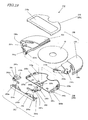
- FIG. 19 is an exploded perspective view illustrating the respective components of a disk cartridge 202.
- the first and second locking lever portions 241 and 242 and the locking lever supporting portion 250 do not form integral parts of the same member in this preferred embodiment as shown in FIG. 19 .
- this preferred embodiment is the same as the first preferred embodiment described above. Therefore, any component having quite or substantially the same function as the counterpart of the first preferred embodiment is identified by the same reference numeral. And the overall structure of the disk cartridge 202 and the operations of opening and closing the disk housing 230 will not be described all over again.
- the locking unit 253' includes first and second locking lever portions 241 ' and 242 ' and a locking lever supporting portion 250.
- the first and second disk housing portions 231 and 232 in the closed state can be kept from rotating.
- the first and second locking lever portions 241 ' and 242 ' can be secured rotatably to the locking lever supporting portion 250 by inserting pivots 250a and 250b on the locking lever supporting portion 250 into the pivot holes 241a and 242a of the first and second locking lever portions 241 ' and 242 ', respectively.
- the first locking lever portion 241 ' includes a latching lever portion 241b, an opener/closer 241c and an elastic portion 241d .
- the latching lever portion 241b fits into the catching portion 231c of the first disk housing portion 231 , thereby preventing the first disk housing portion 231 from turning while the disk housing 230 is closed.
- the operating portion 241 includes the latching lever portion 241b to receive external force, the opener/closer 241c for turning the first locking lever portion 241 externally, and the elastic portion 241d that produces biasing force by deforming elastically responsive to an external manipulation.
- the first locking lever portion 241' includes a latching lever portion 241b , an opener/closer 241c and an elastic portion 241d .
- the latching lever portion 241b fits into the catching portion 231c of the first disk housing portion 231 , thereby preventing the first disk housing portion 231 from turning in the opening direction while the disk housing 230 is closed. If the opener/closer 241c is pressed down externally, the first locking lever portion 241 ' can be biased so as to turn around the pivot hole 241a. And the elastic portion 241d deforms elastically while overcoming the biasing force applied by the opener/closer 241c , thereby producing biasing force in the first locking lever portion 241 .
- the second locking lever portion 242 ' includes a latching lever portion 242b , an opener/closer 242c and an elastic portion 242d .
- the latching lever portion 242b gets engaged with the catching portion 232c of the second disk housing portion 232 , thereby preventing the second disk housing portion 232 from turning in the opening direction while the disk housing 230 is closed. If the opener/closer 242c is pressed down externally, the second locking lever portion 242' can be biased so as to turn around the pivot hole 241b. And the elastic portion 242d deforms elastically while overcoming the biasing force applied by the opener/closer 242c, thereby producing biasing force in the second locking lever portion 242'.
- the disk cartridge 202 has unlocking grooves 200a and 200b for operating the first and second locking lever portions 241' and 242' on the right- and left-hand sides thereof.
- the openers/closers 241c and 242c of the first and second locking lever portions 241' and 242' are designed so as to protrude through the opening at the bottom of the unlocking grooves 200a and 200b , respectively, but not to stick out of the outer shell of the disk cartridge 202 . That is why it is possible to prevent the user from unlocking the disk housing 230 intentionally and carelessly.
- the supporting base member 205 has an insertion port 205t, through which the locking unit 253' is supposed to be inserted.
- FIG. 20 shows perspective views illustrating the structures of the locking unit 253' and the supporting base member 205. Specifically, FIG. 20(a) illustrates the lower supporting base portion 220 and the locking unit 253', while FIG. 20(b) illustrates the upper supporting base portion 210 and the locking unit 253'.
- FIG. 21 shows plan views illustrating the structure of the locking unit 253'. Specifically, FIG. 21(a) illustrates the position of the locking unit 253' yet to be inserted into the supporting base member 205. FIG. 21 (b) illustrates the position of the locking unit 253' being inserted into the supporting base member 205. And FIG. 21(c) illustrates the position of the locking unit 253' that has already been inserted into the supporting base member 205 .
- the locking lever supporting portion 250 includes latching claw portions 251a and 251b , upper latching raised portions 251c and 251d , and lower latching raised portions 251e and 251f , which function as stoppers when the locking unit 253' is inserted and fitted in the direction indicated by the arrow 200A.
- the latching claw portions 251a and 251b engage with portions of the supporting base member 205 in the vicinity of both ends of the insertion port 205t thereof in the longitudinal direction.
- the upper and lower latching raised portions 251c , 251d , 251e and 251f engage with respective parts of the upper and lower supporting base portions 210 and 220 around the center of the edges that form the insertion port 205t.
- the locking lever supporting portion 250 further includes stopper portions 252a and 252b and the first and second locking lever portions 241' and 242' have stopper ribs 241f and 242f, respectively.
- the locking lever supporting portion 250 is made of an elastic material and the body 250t of the locking lever supporting portion 250 has no reinforcing ribs and is easily deformable elastically. That is why when the locking unit 253' is inserted into the supporting base member 205 in the direction indicated by the arrow 200A, the body 250t of the locking lever supporting portion 250 is deformed elastically to flex the entire locking unit 253'. As a result, the assembling process can get done more smoothly.
- the locking lever supporting portion 250 further includes positioning hole cover portions 255a and 255b that will cover the positioning holes 225a and 225b of the lower supporting base portion 220 so as to define recesses with the positioning holes 225a and 225b as bottom holes when the locking unit 253' is fitted into the supporting base member 205. In this manner, it is possible to prevent dust from entering the supporting base member 205 through the positioning holes 225a and 225b.
- the lower supporting base portion 220 has catching portions 221a and 221b to engage with the latching claw portions 251a and 251b of the locking lever supporting portion 250 and catching recessed portions 221c and 221d to engage with the lower latching raised portions 251e and 251f of the locking lever supporting portion 250.
- the catching portions 221a and 221b have a tapered side to get the locking unit 253' inserted easily in the direction indicated by the arrow 200A.
- the lower supporting base portion 220 further has positioning holes 222a and 222b for aligning the lower supporting base portion 220 with the upper supporting base portion 210 when these two portions are joined together.
- the upper supporting base portion 210 has catching recessed portions 211c and 211d to engage with the upper latching raised portions 251c and 251d of the locking holder 250 as shown in FIG. 20(b) .
- the upper supporting base portion 210 further has positioning bosses 212a and 212b to be respectively fitted into the positioning holes 222a and 222b of the lower supporting base portion 220 , thereby aligning these two supporting base portions with each other.
- ribs are arranged in the vicinity of the catching recessed portions 211c , 211d , 221c and 221d of the upper and lower supporting base portions 210 and 220 and around the center of the insertion port 205t in the longitudinal direction. That is why when the upper and lower supporting base portions 210 and 220 are joined and welded or bonded together, not only the ribs on both sides of the supporting base member 205 but also those ribs may be welded or bonded together to join the center portions of the supporting base member 205 together. As a result, even when the locking unit 253' is not fitted yet, the mechanical strength of the supporting base member 205 can also be increased.
- the latching claw portions 251a and 251b of the locking lever supporting portion 250 engage with the catching portions 221a and 221b of the lower supporting base portion 220 and the upper and lower latching raised portions 251c, 251d, 251e and 251f of the locking lever supporting portion 250 respectively engage with the catching recessed portions 211c, 211d, 221c and 221d of the upper and lower supporting base portions 210 and 220. Consequently, the locking unit 253 can be firmly held by the supporting base member 205.
- the locking lever supporting portion 250 gets engaged in this preferred embodiment with the supporting base member 250 in the thickness direction thereof around the center of the supporting base member 205. That is why the degree of engagement at those engaging portions cannot be as much as in the first preferred embodiment. However, by providing latching raised portions to get engaged with the upper and lower supporting base portions 210 and 220 such that the engagement is made at an increased number of points, the locking unit 253' can be held more firmly.
- first and second locking lever portions 241' and 242' and the locking lever supporting portion 250 form the locking unit 253'.
- first and second locking lever portions 241' and 242' and the locking lever supporting portion 250 do not form integral parts unlike the first preferred embodiment described above.
- the first and second locking lever portions 241' and 242' are formed as two identical members (i.e., so as to have the same shape even when turned upside down), thereby cutting down the die cost to make those members and minimizing the arrangement error of those members during the assembling process.
- first and second locking lever portions 241 and 242 are inserted into the locking lever supporting portion 250 without allowing the stopper ribs 241e and 242e of the first and second locking lever portions 241' and 242' to contact with the stopper portions 252a and 252b of the locking lever supporting portion 250 as shown in FIG. 21 (b) .
- first and second locking lever portions 241' and 242' are rotated in the state shown in FIG. 21(b) in the directions indicated by the arrows 241B and 242B, respectively, with the biasing force applied by the elastic portions 241d and 242d, then the stopper ribs 241f and 242f of the first and second locking lever portions 241' and 242' get engaged with the stopper portions 252a and 252b of the locking lever supporting portion 250 as shown in FIG. 21(c) , thus completing the locking unit 253'.
- the stopper ribs 241f and 242f and the stopper portions 252a and 252b overlap with each other along the axis of the pivots 250a and 250b of the locking lever supporting portion 250 , thus preventing the first and second locking lever portions 241' and 242' from coming off the pivots 250a and 250b of the locking lever supporting portion 250. That is why the locking unit 253' can be completed without screwing or fastening with a different member. As a result, the number of members and the number of process steps required can be both cut down.
- first and second locking lever portions 241 ' and 242 ' have contact portions 241e and 242e, respectively.
- the contact portions 241e and 242e will contact with the inner walls of the supporting base member 205 under the biasing force applied by the elastic portions 241d and 242d of the first and second locking levers 241 and 242.
- these contact portions 241e and 242e serve as stoppers, the positional accuracy of the first and second locking levers 241' and 242' in the disk cartridge 201 can be increased.
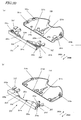
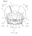
- FIG. 22 is a perspective view illustrating an assembly process in which the disk 10 and the locking unit 253' are inserted into the disk cartridge 202' in the second opening position in which the disk housing 230 has been opened wide enough to insert or remove the disk 10 easily.
- the pivots 220a and 220b of the lower supporting base portion 220 are inserted into the pivot holes 231a and 232b of the first and second disk housing portions 231 and 232 and the upper supporting base portion 210 is either welded or bonded with the lower supporting base portion 220.
- the disk cartridge 202' can be assembled as shown in FIG. 22 .
- the locking unit 253' is also assembled as described above.
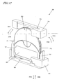
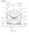
- FIG. 23 is a partial cross-sectional view showing one stage of the assembly process of the disk cartridge 202 and illustrating a situation where the disk cartridge 202' has been opened to the second opening position.
- the first and second disk housing portions 231 and 232 are kept from rotating in the directions indicated by the arrows 231A and 232A by the lower supporting base portion 220 (i.e., the supporting base member 205 ).
- a window 230w' in the second opening position which is wider than the window 230w in the first opening position shown in FIG. 6(b) , is defined.
- the disk 10 may be either inserted in the direction indicated by the arrow 200B or ejected in the direction indicated by the arrow 200A.
- the disk 10 is inserted in the direction indicated by the arrow 200B into the disk cartridge 202'.
- the disk housing 230 has been opened to the second position as shown in FIG. 23 , the disk 10 can be inserted through the window 230w' into the disk cartridge 202'.
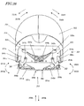
- the disk housing 230 will be fully closed and the disk 10 will get housed in the disk housing 230 as shown in FIG. 24 .
- the locking unit 253' has not been inserted yet, and therefore, the disk housing 230 can be opened or closed freely. If necessary, the disk housing 230 closed may be opened to the second opening position and the disk 10 may be removed.
- the disk drive opens or closes the disk housing 230 with the opening/closing members 151 and 152 of the disk drive fitted into the notches 231d and 232d of the first and second disk housing portions 231 and 232. That is why even the disk cartridge 202' that has no locking unit 253' yet can also be loaded into the disk drive and can have its disk housing 230 opened or closed with no problem. Consequently, the disk cartridge 202' allows the user to insert or remove the disk 10 freely into/from it.
- Such a disk cartridge 202' may be used in a manufacturing or development process step in which the disks 10 need to be changed frequently, e.g., in the process step of testing the disk drive to be loaded with the disk cartridge 202 or during the development of game software.
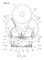
- the openers/closers 241c and 242c of the first and second locking lever portions 241' and 242' will contact with the inner walls of the lower supporting base portion 220 (or supporting base member 205 ) as shown in FIG. 26 .
- the first and second locking lever portions 241 and 242 are turned around the pivots 250a and 250b in the directions indicated by the arrows 241A and 242A , respectively.
- the body 250t of the locking lever supporting portion 250 is deformed elastically.
- the locking unit 253' gets inserted into the supporting base member 205 while being flexed entirely.
- the locking unit 253' being inserted can be deformed significantly in its entirety.
- the load to be placed while the locking unit 253' is inserted can be reduced so much that the locking unit 253' can be inserted easily.
- the disk cartridge 202 can be assembled more easily.
- the locking unit 253' is flexed in its entirety, the latching claw portions 251a and 251b of the locking lever supporting portion 250 gets engaged with the supporting base member 205 earlier than the latching raised portions 251c to 251f. That is to say, since only two of the six latching claw or raised portions get engaged at the same time while the locking unit 253' is being inserted, the locking unit 253' can be inserted with reduced force. As a result, the disk cartridge 202 can be assembled more easily.
- the locking unit 253' in the position shown in FIG. 26 is further inserted deeper in the direction indicated by the arrow 200A, the latching claw portions 251a and 251b get engaged earlier than the latching raised portions 251c to 251f because the locking lever supporting portion 250 is flexed in its entirety as described above. As a result, the locking unit 253' gets fully fitted into the supporting base member 205 as shown in FIG. 27 .
- the latching lever portions 241b and 242b of the first and second locking lever portions 241' and 242' get engaged with the catching portions 231c and 232c of the first and second disk housing portions 231 and 232, thereby keeping the first and second disk housing portions 231 and 232 from rotating in the directions indicated by the arrows 231A and 232A.
- the openers/closers 241c and 242c of the first and second locking lever portions 241' and 242' protrude through the unlocking grooves 200a and 200b on the side surfaces of the supporting base member 205. In this manner, the disk cartridge 202 is completed.
- the first and second locking lever portions 241 and 242 can keep the disk housing 230 in the closed state from rotating.
- the locking unit 253' can keep the first and second disk housing portions 231 and 232 from further rotating in the directions indicated by the arrows 231A and 232A as shown in FIG. 6(b) , thereby avoiding the expansion of the window and preventing the user from removing the disk 10.
- the locking unit 253' Before the locking unit 253' is inserted into the supporting base member 205 of the disk cartridge 202', the first and second disk housing portions 231 and 232 are closed. However, the locking unit 253' may also be inserted even with the first and second disk housing portions 231 and 232 opened.
- FIG. 28 is a partial cross-sectional view illustrating a situation where the locking unit 253' is inserted with the first and second disk housing portions 231 and 232 opened. As shown in FIG. 28 , if the locking unit 253' is inserted with the first and second disk housing portions 231 and 232 opened, then the openers/closers 241c and 242c of the first and second locking lever portions 241' and 242' contact with the catching portions 231c and 232c of the first and second disk housing portions 231 and 232, respectively.
- the first and second disk housing portions 231 and 232 being in contact with the openers/closers 241c and 242c of the first and second locking lever portions 241' and 242' rotate in the directions indicated by the arrows 231B and 232B, respectively. That is why even if the locking unit 253' is inserted with the first and second disk housing portions 231 and 232 opened, the disk housing 230 can also be closed and the disk cartridge 202 can be assembled with no problem at all as the locking unit 253' is inserted deeper.
- the disk cartridge 202 can be assembled just as intended with the number of mistakes reduced during the assembling work.
- the disk housing 230 is closed by itself as the locking unit 253' is inserted, the number of assembling process steps can be cut down, too.
- the locking unit 253' which not only controls the angle of the window defined by the disk housing 230 but also keeps the disk housing 230 in the closed state from rotating, can be inserted as in the first preferred embodiment after the disk cartridge 202' , made up of the disk housing 230 and the supporting base member 205 , has been assembled. For that reason, while the disk cartridge 202' still has no locking unit, the disk housing 230 can also be opened wide enough to readily remove the disk 10 from the disk cartridge. That is why the assembling process of the disk cartridge 202 can be completed by inserting the locking unit 253' through the insertion port of the supporting base member 205 after the disk 10 has been inserted into the disk cartridge 202'.
- the manufacturing process of the disk 10 and the assembling process of the disk cartridge 202 can be totally separated from each other. Consequently, a disk cartridge manufacturing process can be carried out with the manufacturing process of the disk 10 and the assembling process of the disk cartridge 202, which have quite different process and testing methods, performed in two different places, thus increasing the degree of flexibility of the manufacturing process and cutting down the manufacturing costs significantly.
- the disk housing 230 in the closed state can be kept from rotating and the angle of the window defined by the disk housing 230 opened can be controlled so as to prevent the user from removing the disk 10 from the disk cartridge 202.
- first and second locking lever portions 241' and 242' and the locking lever supporting portion 250 are provided separately in this preferred embodiment.
- the first and second locking lever portions 241' and 242' can be rotated around the pivots and the rotating operation can be stabilized.
- the first and second locking lever portions 241' and 242' are made of a different material from that of the locking lever supporting portion 250, then the elasticity of the elastic portions 241d and 242d of the first and second locking lever portions 241' and 242' can be optimized.
- the first and second locking lever portions 241' and 242' and the locking lever supporting portion 250 can be designed much more flexibly.
- the present invention can be used effectively in a disk cartridge of any type, which is designed to house not only an optical disk but also a magnetic disk, a magnetooptical disk or any other disklike storage medium on which data is written by any arbitrary recording method.
- the present invention is applicable particularly effectively to a disk cartridge that is designed to house a disklike storage medium of a small size.
Landscapes
- Feeding And Guiding Record Carriers (AREA)
- Packaging Of Machine Parts And Wound Products (AREA)
Claims (10)
- Cartouche à disque (201) comprenant :- de première et deuxième parties de logement de disque (231, 232), chacune d'elles définissant un espace pour loger une partie d'un disque (10), avec une couche de stockage d'informations sur au moins une de ses faces, et celles-ci logeant le disque (10) dans son entièreté lorsqu'elles sont assemblées ;- un élément de base de support (205) comportant une partie de rotation et de support de logement de disque pour permettre une rotation et soutenir les première et deuxième parties de logement de disque (231, 232), de manière à ouvrir ou fermer une fenêtre (230w) par rapport au disque (10), de sorte que le disque (10) soit serré de façon externe, et une tête pouvant accéder au disque (10) et lire et écrire des informations depuis/sur sa couche de stockage d'informations par la fenêtre (230w) ;caractérisée par :- une unité de verrouillage (253), qui inclut de première et deuxième parties de levier de verrouillage (241, 242) pour maintenir les première et deuxième parties de logement de disque (231, 232) fermées et empêchées de tourner et une partie de support de levier de verrouillage (250), qui soutient les première et deuxième parties de levier de verrouillage (241, 242) en autorisant une rotation et qui est fixée à l'élément de base de support (205) ;- dans laquelle l'élément de base de support (205) comporte un orifice d'insertion (205t) pour insérer l'unité de verrouillage (253) ;- dans laquelle, pendant que l'unité de verrouillage (253) reste encore à insérer dans l'élément de base de support (205) par l'orifice d'insertion (205t) , les première et deuxième parties de logement de disque (231, 232) ouvrent la fenêtre (230w) avec un angle de rotation suffisamment large pour pouvoir retirer le disque (10) facilement ; et- dans laquelle, avec la partie de support de levier de verrouillage (250) insérée dans l'élément de base de support (205) par l'orifice d'insertion (205t), les première et deuxième parties de logement de disque (231, 232) viennent au contact de l'unité de verrouillage (253) et ont leur angle de rotation limité, ce qui commande ainsi la taille de la fenêtre (230w) de sorte que le disque (10) soit inamovible.
- Cartouche à disque (201) selon la revendication 1, dans laquelle, pendant qu'elle est insérée dans l'élément de base de support (205) par l'orifice d'insertion (205t), l'unité de verrouillage (253) fait tourner les première et deuxième parties de logement de disque (231, 232), tout en venant au contact de parties des première et deuxième parties de logement de disque (231, 232), fermant ainsi la fenêtre (230w).
- Cartouche à disque (201) selon la revendication 2, dans laquelle l'orifice d'insertion (205t) de l'élément de base de support (205) a une forme sensiblement rectangulaire ; et- dans laquelle la partie de support de levier de verrouillage (250) inclut un corps (250t) qui ferme l'orifice d'insertion (205t) complètement lorsque l'unité de verrouillage (253) est insérée dans l'élément de base de support (205).
- Cartouche à disque (201) selon la revendication 3, dans laquelle l'élément de base de support (205) inclut une première paire de parties de saisie (211a, 211b, 221a, 221b) au voisinage des deux extrémités du corps (250t) dans sa direction longitudinale ; et- dans laquelle la partie de support de levier de verrouillage (250) inclut une première paire de parties d'accrochage (251a, 251b) qui viennent au contact de la première paire de parties de saisie (211a, 211b, 221a, 221b) lorsque l'unité de verrouillage (253) est insérée dans l'élément de base de support (205).
- Cartouche à disque (201) selon la revendication 4, dans laquelle l'élément de base de support (205) inclut une deuxième paire de parties de saisie (211c, 211d, 221c, 221d) autour du centre du corps (250t) dans sa direction longitudinale ; et- dans laquelle la partie de support de levier de verrouillage (250) inclut une deuxième paire de parties d'accrochage (251d, 251c) qui viennent au contact de la deuxième paire de parties de saisie (211c, 211d, 221c, 221d) lorsque l'unité de verrouillage (253) est insérée dans l'élément de base de support (205).
- Cartouche à disque (201) selon la revendication 5, dans laquelle la partie de support de levier de verrouillage (250) est faite en un matériau élastique ; et- dans laquelle en insérant la partie de support de levier de verrouillage (250) dans l'élément de base de support (205) par l'orifice d'insertion (205t), tout en déformant la partie de support de levier de verrouillage (250) élastiquement, les première et deuxième paires de parties d'accrochage (251a, 251b, 251c, 251d) sont amenées au contact des première et deuxième paires de parties de saisie (211a, 211b, 221a, 221b, 211c, 211d, 221c, 221d), respectivement.
- Cartouche à disque (201) selon la revendication 1, dans laquelle chacune des première et deuxième parties de levier de verrouillage (241, 242) inclut une partie élastique (241d, 242d) qui produit une force de sollicitation dans sa direction de rotation.
- Cartouche à disque (201) selon la revendication 7, dans laquelle les première et deuxième parties de levier de verrouillage (241, 242) et la partie de support de levier de verrouillage (250) font partie intégrante et chacune des première et deuxième parties de levier de verrouillage (241, 242) est fixée à la partie de support de levier de verrouillage (250) de façon à tourner autour d'une partie formant charnière (250a, 250b).
- Cartouche à disque (201) selon la revendication 8, dans laquelle l'élément de base de support (205) comporte un trou de positionnement (225a, 225b) pour positionner l'élément de base de support (205) de façon externe ; et- dans laquelle la partie de support de levier de verrouillage (250) inclut une partie de recouvrement (255a, 255b) qui recouvre le trou de positionnement (225a, 225b), de sorte qu'une cavité ayant le trou de positionnement (225a, 225b) comme fond ouvert soit définie lorsque l'unité de verrouillage (253) est insérée dans l'élément de base de support (205).
- Cartouche à disque (201) selon la revendication 9, dans laquelle l'élément de base de support (205) chevauche au moins partiellement les première et deuxième parties de logement de disque (231, 232), de façon à empêcher les première et deuxième parties de logement de disque (231, 232) de se déplacer perpendiculairement au disque (10).
Priority Applications (1)
| Application Number | Priority Date | Filing Date | Title |
|---|---|---|---|
| EP12002318.9A EP2485219B1 (fr) | 2006-10-12 | 2007-10-11 | Cartouche de disque |
Applications Claiming Priority (3)
| Application Number | Priority Date | Filing Date | Title |
|---|---|---|---|
| JP2006278714 | 2006-10-12 | ||
| JP2007110249 | 2007-04-19 | ||
| PCT/JP2007/069884 WO2008044743A1 (fr) | 2006-10-12 | 2007-10-11 | Cartouche à disque |
Related Child Applications (2)
| Application Number | Title | Priority Date | Filing Date |
|---|---|---|---|
| EP12002318.9A Division EP2485219B1 (fr) | 2006-10-12 | 2007-10-11 | Cartouche de disque |
| EP12002318.9 Division-Into | 2012-03-30 |
Publications (3)
| Publication Number | Publication Date |
|---|---|
| EP2073209A1 EP2073209A1 (fr) | 2009-06-24 |
| EP2073209A4 EP2073209A4 (fr) | 2011-10-12 |
| EP2073209B1 true EP2073209B1 (fr) | 2012-12-12 |
Family
ID=39282933
Family Applications (2)
| Application Number | Title | Priority Date | Filing Date |
|---|---|---|---|
| EP12002318.9A Not-in-force EP2485219B1 (fr) | 2006-10-12 | 2007-10-11 | Cartouche de disque |
| EP07829622A Not-in-force EP2073209B1 (fr) | 2006-10-12 | 2007-10-11 | Cartouche à disque |
Family Applications Before (1)
| Application Number | Title | Priority Date | Filing Date |
|---|---|---|---|
| EP12002318.9A Not-in-force EP2485219B1 (fr) | 2006-10-12 | 2007-10-11 | Cartouche de disque |
Country Status (5)
| Country | Link |
|---|---|
| US (1) | US8108885B2 (fr) |
| EP (2) | EP2485219B1 (fr) |
| JP (1) | JP4527169B2 (fr) |
| CN (1) | CN101512655B (fr) |
| WO (1) | WO2008044743A1 (fr) |
Families Citing this family (3)
| Publication number | Priority date | Publication date | Assignee | Title |
|---|---|---|---|---|
| US8108885B2 (en) | 2006-10-12 | 2012-01-31 | Panasonic Corporation | Disk cartridge |
| JP5042048B2 (ja) * | 2007-01-22 | 2012-10-03 | パナソニック株式会社 | ディスク装置 |
| WO2009037836A1 (fr) * | 2007-09-18 | 2009-03-26 | Panasonic Corporation | Dispositif de disque optique |
Family Cites Families (26)
| Publication number | Priority date | Publication date | Assignee | Title |
|---|---|---|---|---|
| US3788576A (en) * | 1972-12-11 | 1974-01-29 | Ibm | Magnetic tape cartridge and storage apparatus |
| DE2364397B2 (de) * | 1973-12-22 | 1977-02-03 | Basf Ag, 6700 Ludwigshafen | Magnetbandkassette und geraet dafuer |
| JPS60115056A (ja) * | 1983-11-26 | 1985-06-21 | Toshiba Corp | カ−トリツジ装着装置 |
| US4695911A (en) * | 1985-05-03 | 1987-09-22 | Ron Loosen | Floppy diskette protection device |
| JPS623477A (ja) * | 1985-06-28 | 1987-01-09 | Toshiba Corp | 情報記憶媒体カセツト |
| US4740949A (en) * | 1985-08-16 | 1988-04-26 | Laser Magnetic Storage International Company | Laser access apparatus for optical disk drive |
| JPH0754221B2 (ja) | 1986-12-17 | 1995-06-07 | 松下冷機株式会社 | 空気調和機 |
| JPS63153373U (fr) * | 1987-03-25 | 1988-10-07 | ||
| JPS6423776A (en) | 1987-07-16 | 1989-01-26 | Mitsubishi Electric Corp | High tension pulse generator |
| JPS6423776U (fr) * | 1987-07-29 | 1989-02-08 | ||
| JPH09153264A (ja) | 1995-11-29 | 1997-06-10 | Matsushita Electric Ind Co Ltd | ディスクカートリッジ |
| JP3313562B2 (ja) * | 1996-02-09 | 2002-08-12 | 株式会社日立製作所 | ディスクカートリッジ及びそれを用いたディスク装置 |
| JP4006809B2 (ja) * | 1998-02-02 | 2007-11-14 | ソニー株式会社 | 情報記憶媒体カートリッジ |
| JP2001035119A (ja) * | 1999-07-21 | 2001-02-09 | Sony Corp | ディスクカートリッジ及び記録再生装置 |
| US6687215B1 (en) * | 2000-04-12 | 2004-02-03 | Dphi Acquisitions, Inc. | Low profile and medium protecting cartridge assembly |
| US6862739B1 (en) * | 2000-10-27 | 2005-03-01 | Hewlett-Packard Development Company, L.P. | Scalable and portable disc player for various optical disc sizes |
| US6816340B2 (en) * | 2001-03-14 | 2004-11-09 | Fuji Photo Film Co., Ltd. | Disk cartridge |
| JP2002279751A (ja) * | 2001-03-16 | 2002-09-27 | Fuji Photo Film Co Ltd | ディスクカートリッジ |
| JP2003051171A (ja) * | 2001-05-21 | 2003-02-21 | Fuji Photo Film Co Ltd | ディスクカートリッジ |
| JP2003059228A (ja) * | 2001-08-21 | 2003-02-28 | Fuji Photo Film Co Ltd | ディスクカートリッジ |
| CN100349227C (zh) * | 2002-10-10 | 2007-11-14 | 松下电器产业株式会社 | 磁盘盒 |
| US7673311B2 (en) * | 2002-10-10 | 2010-03-02 | Panasonic Corporation | Disc cartridge for storage of a disc |
| US7340753B2 (en) * | 2002-11-01 | 2008-03-04 | Matsushita Electric Industrial Co., Ltd. | Disk drive |
| KR101059493B1 (ko) * | 2003-07-28 | 2011-08-25 | 소니 가부시키가이샤 | 디스크 카트리지용 셔터 부재, 디스크 카트리지 및 디스크 기록 또는 재생 장치 |
| WO2005055234A1 (fr) * | 2003-12-05 | 2005-06-16 | Koninklijke Philips Electronics N.V. | Boitier pour un disque |
| US8108885B2 (en) | 2006-10-12 | 2012-01-31 | Panasonic Corporation | Disk cartridge |
-
2007
- 2007-10-11 US US12/374,753 patent/US8108885B2/en not_active Expired - Fee Related
- 2007-10-11 CN CN200780033071XA patent/CN101512655B/zh not_active Expired - Fee Related
- 2007-10-11 EP EP12002318.9A patent/EP2485219B1/fr not_active Not-in-force
- 2007-10-11 JP JP2008538758A patent/JP4527169B2/ja not_active Expired - Fee Related
- 2007-10-11 EP EP07829622A patent/EP2073209B1/fr not_active Not-in-force
- 2007-10-11 WO PCT/JP2007/069884 patent/WO2008044743A1/fr active Application Filing
Also Published As
| Publication number | Publication date |
|---|---|
| CN101512655A (zh) | 2009-08-19 |
| EP2485219A1 (fr) | 2012-08-08 |
| EP2485219B1 (fr) | 2014-05-21 |
| CN101512655B (zh) | 2012-05-16 |
| WO2008044743A1 (fr) | 2008-04-17 |
| US8108885B2 (en) | 2012-01-31 |
| US20090235294A1 (en) | 2009-09-17 |
| EP2073209A1 (fr) | 2009-06-24 |
| JPWO2008044743A1 (ja) | 2010-02-18 |
| JP4527169B2 (ja) | 2010-08-18 |
| EP2073209A4 (fr) | 2011-10-12 |
Similar Documents
| Publication | Publication Date | Title |
|---|---|---|
| AU2002225396B2 (en) | Disc cartridge | |
| US8209712B2 (en) | Disk cartridge with rotatably supported disk storage portions | |
| EP2073209B1 (fr) | Cartouche à disque | |
| EP1571660B1 (fr) | Unite de disque | |
| EP2037458B1 (fr) | Dispositif à disque | |
| EP2043099B1 (fr) | Dispositif à disque | |
| US8037487B2 (en) | Optical disk device | |
| JP3776383B2 (ja) | ディスクカートリッジ | |
| US7853965B2 (en) | Disk drive | |
| JP4324666B2 (ja) | ディスクカートリッジ | |
| US7448056B2 (en) | Disc cartridge | |
| JP3405983B1 (ja) | ディスクカートリッジ | |
| JP2003228948A (ja) | ディスクカートリッジ | |
| JP3776444B2 (ja) | ディスクカートリッジ | |
| JP3776445B2 (ja) | ディスクカートリッジ | |
| JP3776440B2 (ja) | ディスクカートリッジ | |
| JP4142603B2 (ja) | ディスクカートリッジ | |
| JP3892024B2 (ja) | ディスクカートリッジ | |
| JP3405984B1 (ja) | ディスクカートリッジ | |
| JP4142602B2 (ja) | ディスクカートリッジ | |
| JP2003228949A (ja) | ディスクカートリッジ | |
| JP2005251387A (ja) | ディスクカートリッジ |
Legal Events
| Date | Code | Title | Description |
|---|---|---|---|
| PUAI | Public reference made under article 153(3) epc to a published international application that has entered the european phase |
Free format text: ORIGINAL CODE: 0009012 |
|
| 17P | Request for examination filed |
Effective date: 20090121 |
|
| AK | Designated contracting states |
Kind code of ref document: A1 Designated state(s): AT BE BG CH CY CZ DE DK EE ES FI FR GB GR HU IE IS IT LI LT LU LV MC MT NL PL PT RO SE SI SK TR |
|
| AX | Request for extension of the european patent |
Extension state: AL BA HR MK RS |
|
| RBV | Designated contracting states (corrected) |
Designated state(s): DE FR GB |
|
| A4 | Supplementary search report drawn up and despatched |
Effective date: 20110914 |
|
| RIC1 | Information provided on ipc code assigned before grant |
Ipc: G11B 23/03 20060101AFI20110908BHEP |
|
| GRAP | Despatch of communication of intention to grant a patent |
Free format text: ORIGINAL CODE: EPIDOSNIGR1 |
|
| GRAC | Information related to communication of intention to grant a patent modified |
Free format text: ORIGINAL CODE: EPIDOSCIGR1 |
|
| DAX | Request for extension of the european patent (deleted) | ||
| GRAS | Grant fee paid |
Free format text: ORIGINAL CODE: EPIDOSNIGR3 |
|
| GRAA | (expected) grant |
Free format text: ORIGINAL CODE: 0009210 |
|
| AK | Designated contracting states |
Kind code of ref document: B1 Designated state(s): DE FR GB |
|
| REG | Reference to a national code |
Ref country code: GB Ref legal event code: FG4D |
|
| REG | Reference to a national code |
Ref country code: DE Ref legal event code: R096 Ref document number: 602007027371 Country of ref document: DE Effective date: 20130131 |
|
| PLBE | No opposition filed within time limit |
Free format text: ORIGINAL CODE: 0009261 |
|
| STAA | Information on the status of an ep patent application or granted ep patent |
Free format text: STATUS: NO OPPOSITION FILED WITHIN TIME LIMIT |
|
| 26N | No opposition filed |
Effective date: 20130913 |
|
| REG | Reference to a national code |
Ref country code: DE Ref legal event code: R097 Ref document number: 602007027371 Country of ref document: DE Effective date: 20130913 |
|
| GBPC | Gb: european patent ceased through non-payment of renewal fee |
Effective date: 20131011 |
|
| REG | Reference to a national code |
Ref country code: DE Ref legal event code: R119 Ref document number: 602007027371 Country of ref document: DE Effective date: 20140501 |
|
| PG25 | Lapsed in a contracting state [announced via postgrant information from national office to epo] |
Ref country code: GB Free format text: LAPSE BECAUSE OF NON-PAYMENT OF DUE FEES Effective date: 20131011 |
|
| REG | Reference to a national code |
Ref country code: FR Ref legal event code: ST Effective date: 20140630 |
|
| PG25 | Lapsed in a contracting state [announced via postgrant information from national office to epo] |
Ref country code: DE Free format text: LAPSE BECAUSE OF NON-PAYMENT OF DUE FEES Effective date: 20140501 Ref country code: FR Free format text: LAPSE BECAUSE OF NON-PAYMENT OF DUE FEES Effective date: 20131031 |