US7340753B2 - Disk drive - Google Patents
Disk drive Download PDFInfo
- Publication number
- US7340753B2 US7340753B2 US10/533,048 US53304805A US7340753B2 US 7340753 B2 US7340753 B2 US 7340753B2 US 53304805 A US53304805 A US 53304805A US 7340753 B2 US7340753 B2 US 7340753B2
- Authority
- US
- United States
- Prior art keywords
- shutter
- disk cartridge
- disk
- disk drive
- rotational member
- Prior art date
- Legal status (The legal status is an assumption and is not a legal conclusion. Google has not performed a legal analysis and makes no representation as to the accuracy of the status listed.)
- Expired - Fee Related, expires
Links
Images


Classifications
-
- G—PHYSICS
- G11—INFORMATION STORAGE
- G11B—INFORMATION STORAGE BASED ON RELATIVE MOVEMENT BETWEEN RECORD CARRIER AND TRANSDUCER
- G11B17/00—Guiding record carriers not specifically of filamentary or web form, or of supports therefor
- G11B17/02—Details
- G11B17/04—Feeding or guiding single record carrier to or from transducer unit
- G11B17/041—Feeding or guiding single record carrier to or from transducer unit specially adapted for discs contained within cartridges
- G11B17/043—Direct insertion, i.e. without external loading means
- G11B17/0436—Direct insertion, i.e. without external loading means with opening mechanism of the cartridge shutter
-
- G—PHYSICS
- G11—INFORMATION STORAGE
- G11B—INFORMATION STORAGE BASED ON RELATIVE MOVEMENT BETWEEN RECORD CARRIER AND TRANSDUCER
- G11B17/00—Guiding record carriers not specifically of filamentary or web form, or of supports therefor
- G11B17/02—Details
- G11B17/04—Feeding or guiding single record carrier to or from transducer unit
- G11B17/041—Feeding or guiding single record carrier to or from transducer unit specially adapted for discs contained within cartridges
- G11B17/044—Indirect insertion, i.e. with external loading means
- G11B17/047—Indirect insertion, i.e. with external loading means with sliding loading means
- G11B17/0476—Indirect insertion, i.e. with external loading means with sliding loading means with opening mechanism of the cartridge shutter
-
- G—PHYSICS
- G11—INFORMATION STORAGE
- G11B—INFORMATION STORAGE BASED ON RELATIVE MOVEMENT BETWEEN RECORD CARRIER AND TRANSDUCER
- G11B23/00—Record carriers not specific to the method of recording or reproducing; Accessories, e.g. containers, specially adapted for co-operation with the recording or reproducing apparatus ; Intermediate mediums; Apparatus or processes specially adapted for their manufacture
- G11B23/02—Containers; Storing means both adapted to cooperate with the recording or reproducing means
- G11B23/03—Containers for flat record carriers
- G11B23/0301—Details
- G11B23/0308—Shutters
Definitions
- the present invention relates to a disk drive for reading and/or writing data from/on a disklike data storage medium such as an optical disc or a magnetic disk, which is stored in a cartridge type container.
- Disklike data storage media are used extensively to store software or data for computer-related equipment, music, video and various other types of information thereon. Data may be read or written with a light beam or magnetism. Examples of data storage media using a light beam include CDs and DVDs. A floppy disk has been known as a data storage medium that used magnetism. Furthermore, some data storage media such as MOs and MDs use both a light beam and magnetism alike.
- a data storage medium of the type allowing the user to rewrite data is housed in a cartridge type storage case to protect the data stored there.
- the disk cartridge 100 includes a cartridge body 101 to store a readable and/or rewritable disk 10 .
- the cartridge body 101 has a window 101 w on the upper and lower surfaces thereof so as to allow a drive mechanism (such as a spindle motor) for rotating the disk 10 and a read/write head to enter the cartridge body 101 and access the disk 10 .
- a drive mechanism such as a spindle motor
- the disk cartridge 100 further includes a shutter 103 with a square bottom and a C-cross section in order to cover the window 101 w on the upper and lower surfaces of the cartridge body 101 and to protect the side of the disk 10 exposed through the window 101 w.
- the shutter 103 is movable in the direction pointed by the arrow P.
- a spring (not shown) applies elastic force to the shutter 103 so as to make the shutter 103 shut the window 101 w .
- the shutter 103 shuts the window 101 w so as not to expose the disk 10 .
- a shutter opener 104 In reading or writing data from/on the disk cartridge 100 using a disk drive (not shown), a shutter opener 104 , provided for the disk drive, is used. Specifically, the protrusion 104 a of the shutter opener 104 is fitted with a notched portion 103 a of the shutter 103 , and the disk cartridge 100 is pushed deeply into the disk drive in the direction pointed by the arrow Q. As a result, the shutter opener 104 turns around the center of rotation 104 b in the direction pointed by the arrow R, thereby shifting the shutter 103 in the direction pointed by the arrow P. In this manner, the shutter 103 can be opened.
- the shutter 103 of the disk cartridge 100 has a square bottom and a C-cross section as described above. However, it is usually difficult to make a shutter in such a shape. Also, to make the shutter slide smoothly, the shutter needs to be shaped with high precision. As a result, the cost of this part rises and eventually the cost of the disk cartridge 100 itself goes up, too.
- the shutter 103 with such a structure easily leaves a gap between the shutter 103 and the cartridge body 101 even while the window 101 w on the upper and lower surfaces of the cartridge body 101 is closed.
- Japanese Patent Application Laid-Open Publication No. 2002-50148 discloses a disk cartridge having a structure in which the window is opened or closed with a plurality of planar shutters.
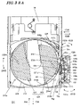
- FIG. 64 is a perspective view of such a cartridge 200 .
- FIG. 65 is an exploded perspective view illustrating the respective members of the cartridge 200 .
- the disk cartridge 200 includes a cartridge body 210 consisting of an upper shell 211 and a lower shell 212 .
- the lower shell 212 has a window 212 w on its lower surface so as to allow a drive mechanism (such as a spindle motor) for rotating the disk 10 and a read/write head to enter the cartridge body 210 and access the disk 10 .
- a drive mechanism such as a spindle motor
- On the outer surface of the lower shell 212 provided are positioning holes 215 a and 215 b for positioning the disk cartridge 200 on a plane parallel to the disk 10 within a disk drive (not shown) and a notch 212 t for preventing the user from inserting the disk cartridge 200 upside down.
- a first link spindle 212 a and a second link spindle 212 b are provided on the inner surface of the lower shell 212 .
- a window 212 g for exposing a part of the outer periphery of a rotational member 230 (to be described later) is provided on a side surface of the lower shell 212 .
- Two guide portions 212 G and 212 H are provided on both ends of the window 212 g.
- a shutter pair 220 for shutting the window 212 w , a rotational member 230 that rotates around a point substantially matching the center of the disk 10 , and a locking member 225 .
- the shutter pair 220 consists of a first shutter 221 and a second shutter 222 .
- the rotational member 230 has a disk shape and also has a window 230 w , which is positioned and shaped so as to completely match the window 212 w when the shutter pair 220 is fully opened. Also, on the side surface of this rotational member 230 , a first notched portion 231 , a second notched portion 232 and a gear portion 233 located between the two notched portions 231 and 232 are provided so as to rotate and drive the rotational member 230 externally. On the lower surface of the rotational member 230 opposed to the shutter pair 220 , rotation spindles 230 a and 230 b are provided for the first and second shutters 221 and 222 , respectively.
- the first shutter 221 has a rotation center hole 221 a and a link groove 221 b to which the rotation spindle 230 a and the first link spindle 212 a are respectively inserted
- the second shutter 222 has a rotation center hole 222 a and a link groove 222 b to which the rotation spindle 230 b and the second link spindle 212 b are respectively inserted.
- the first and second shutters 221 and 222 turn on the rotation spindles 230 a and 230 b , respectively.
- the locking member 225 is supported in a rotatable position on a rotation shaft 212 c provided for the lower shell 212 . While the window 212 w is closed, the convex portion 225 a of the locking member 225 fits into the second notched portion 232 of the rotational member 230 , thereby locking the rotational member 230 and keeping it from rotating.
- the upper shell 211 covers the entire upper surface of the disk 10 , and therefore, a damper 240 is provided inside to clamp the disk 10 thereon.
- FIGS. 66 through 68 respectively illustrate a fully closed state, an opening state, and a fully opened state of the shutter pair 220 .
- the rotation center holes 221 a and 222 a of the first and second shutters 221 and 222 also rotate in those directions.
- the link grooves 221 b and 222 b slide along the first and second link spindles 212 a and 212 b in the directions pointed by the arrows T 2 and U 2 , respectively.
- the first and second shutters 221 and 222 move in the directions pointed by the arrows T 2 and U 2 , respectively, while rotating around their rotation center holes 221 a and 222 a in the directions pointed by the arrows T 1 and U 1 , respectively, as shown in FIG. 67 .
- the shutter pair 220 is fully opened as shown in FIG. 68 .
- the window 212 w of the lower shell 212 substantially matches the window 230 w of the rotational member 230 . Consequently, a drive mechanism (such as a spindle motor) for rotating and driving the disk 10 and a read/write head can now enter the cartridge body 210 and access the disk 10 stored in the disk cartridge 200 .
- a drive mechanism such as a spindle motor
- the window 212 w may be shut by performing the opposite of the opening operation described above, i.e., by rotating the rotational member 230 in the direction pointed by the arrow S′.
- the locking member 225 is turned on its rotation shaft 212 c in the direction pointed by the arrow 225 A′ by the elastic portion 225 c provided for the locking member 225 itself, thereby getting the convex portion 225 a of the locking member 225 fitted with the second notched portion 232 of the rotational member 230 again. In this manner, the rotational member 230 is locked so as not to rotate and the shutter closing operation is finished.
- the rotational member 230 cannot rotate freely, but only to a predetermined degree, between the opened and closed states of the shutter pair 220 .
- the rotational member 230 cannot rotate freely, but only to a predetermined degree, between the opened and closed states of the shutter pair 220 .
- the rotational member 230 has rotated with respect to the cartridge body 210 , at least one of the first and second notched portions 231 and 232 and the gear portion 233 is exposed through the window 212 g provided on the side surface of the cartridge body 210 .
- the shutter pair 220 can be operated no matter in what state the shutter pair 220 is.
- the disk cartridge needs to be held firmly.
- One of the easiest and safest ways to fill this need is to provide holding members 210 a and 210 b for the disk drive as shown in FIGS. 66 through 68 for the purpose of gripping the cartridge body 210 (of which only the lower shell 212 is shown in these drawings) on the side surfaces thereof.
- Japanese Patent Application Laid-Open Publication No. 2002-50148 discloses a rack bar 250 , including a first fitting convex portion 251 , a gear portion 253 and a second fitting convex portion 252 , which are arranged in line, as a means for rotating the rotational member 230 .
- the first fitting convex portion 251 , gear portion 253 and second fitting convex portion 252 respectively fit with a first notched portion 231 , a gear portion 233 and a second notched portion 232 provided on the side surface of the rotational member 230 .
- a side surface portion 231 a with the first notched portion 231 is as high as the addendum plane of the gear portion 233 .
- a side surface portion 232 a with the second notched portion 232 is also as high as the addendum plane of the gear portion 233 .
- the rack bar 250 is slid from the location shown in FIG. 69 to that shown in FIG. 70 in the direction pointed by the arrow 250 A (i.e., substantially parallel to the side surface of the disk cartridge 200 ), thereby rotating the rotational member 230 as described above.
- a holding member 210 a for holding the disk cartridge 200 firmly interferes with the shifting space of the rack bar 250 .
- the rack bar 250 could not be held firmly with the holding member 210 a anymore, which is a problem.
- the rack bar 250 is an integrally molded member, then the rack bar 250 and the rotational member 230 are interlocked together by utilizing the elasticity of the resin that makes the rack bar 250 . Accordingly, the elasticity of the rack bar 250 may not be controllable appropriately. In that case, the rack bar 250 may not engage or disengage itself with/from the outer surface of the disk cartridge 200 smoothly enough. Or after having gone through a number of opening and closing operations, the rack bar 250 may be deformed plastically and may not be interlocked with the rotational member 230 perfectly anymore.
- an object of the present invention is to provide a disk drive, which is adapted to a disk cartridge that opens and closes its shutters by rotating a rotational member and which can contribute to opening and closing the shutters with good stability and more certainty by using a simple mechanism.
- a disk drive is adapted for use with a disk cartridge including: a disk; a body to store the disk therein; a window, which is provided for the body to allow a head to access the disk to read and/or write data from/on the disk; a shutter for opening or shutting the window; and a rotational member, which includes a gear portion and first and second notched portions to sandwich the gear portion and which interlocks with the shutter.
- the disk drive includes: a motor for spinning the disk; a transporting portion for holding and transporting the disk cartridge between a position where the motor is ready to spin the disk and a position where the disk cartridge is loaded into, or unloaded from, the disk drive; the head for reading and/or writing the data; and a shutter driving mechanism, which includes a rack portion that engages with the gear portion, and first and second driving levers that are supported to fit into, and turn with, the first and second notched portions, respectively.
- the transporting portion includes a first cam structure for driving the first and second driving levers of the shutter driving mechanism such that the first and second driving levers swing as the transporting portion moves. As the transporting portion moves, the first and second notched portions and the gear portion of the disk cartridge held on the transporting portion get engaged with the shutter driving mechanism, which then rotates the rotational member so as to open or close the shutter.
- the first and second driving levers are supported in rotatable positions on the rack portion.
- first and second driving levers include fitting portions to fit into the first and second notched portions, respectively, and the shutter driving mechanism applies elastic force to the first and second driving levers such that the fitting portions of the first and second driving levers are pressed toward the transporting portion.
- the shutter driving mechanism further includes: a base portion for supporting the rack portion such that the rack portion is movable perpendicularly to the direction in which the transporting portion is transported; and a second force applying structure for applying an elastic force to the rack portion toward the transporting portion.
- the transporting portion includes a second cam structure for driving the rack portion perpendicularly to the transporting direction.
- the transporting portion has a side surface that is opposed to the shutter driving mechanism and that includes the first and second cam structures thereon.
- the transporting portion has a guide wall for holding the disk cartridge at a predetermined position.
- the first cam structure contacts with the first and second driving levers.
- the second cam structure has a second guide surface that contacts with the rack portion.
- the transporting portion has a side surface opposed to the shutter driving mechanism, and the first and second guide surfaces are provided parallel to each other on the side surface of the transporting portion.
- the first cam structure drives the first and second driving levers such that the fitting portions of the first and second driving levers fit with only the first and second notched portions without contacting with any other portion of the side surface of the disk cartridge.
- the shutter driving mechanism includes a guide rib for guiding the transporting portion.
- the guide rib may be provided for the rack portion.
- the guide rib may be provided for the base portion.
- a pitch as measured from the second notched portion of the rotational member to either a tooth or a groove, which is located at one end of the gear portion closest to the second notched portion is equal to a pitch as measured from the fitting portion of the second driving lever to either a groove or a tooth, which is located at one end of the rack portion closest to the second driving lever.
- a pitch as measured from the second notched portion of the rotational member to either a tooth or a groove, which is located at one end of the gear portion closest to the second notched portion is longer by one tooth than a pitch as measured from the fitting portion of the second driving lever to either a groove or a tooth, which is located at one end of the rack portion closest to the second driving lever.
- first and second driving levers are arranged in the shutter driving mechanism, and one tooth of the rack portion, which is located closest to the second lever, is chamfered, such that as the shutter of the disk cartridge is going to be closed, the second lever gets interlocked with the rotational member of the disk cartridge earlier than the first lever.
- the force applied by the second force applying structure is greater than that applied by the first force applying structure.
- the first cam structure drives the first and second driving levers such that as the transporting portion is going to load the disk cartridge into the disk drive, the first driving lever, the rack portion and the second driving lever contact with the rotational member of the disk cartridge in this order.
- the first cam structure drives the first and second driving levers
- the second cam structure drives the rack portion, such that as the transporting portion is going to load the disk cartridge into the disk drive, the first driving lever, the rack portion and the second driving lever contact with the rotational member of the disk cartridge in this order.
- the rack portion while the transporting portion is unloading the disk cartridge from the disk drive, the rack portion is able to engage with the gear portion at least in first and second positions, and no matter whether the rack portion has engaged with the gear portion in the first position or the second position, the shutter is closable.
- the first and second driving levers are driven so as to avoid contact with the disk cartridge.
- the rack portion is driven so as to avoid contact with the disk cartridge.
- the transporting portion moves a predetermined distance after the shutter of the disk cartridge has been either opened or closed.
- the transporting portion has a recess on which another disk cartridge, having a different shape from that of the disk cartridge, is mountable.
- the disk cartridge includes a locking member for keeping the rotational member from rotating, and the first cam structure drives the first and second driving levers such that the first and second driving levers avoid contact with the locking member.
- FIG. 1 is an exploded perspective view illustrating a configuration for a disk drive according to a first preferred embodiment of the present invention
- FIG. 2 is a plan view showing a situation where the disk cartridge shown in FIG. 64 has been mounted on the tray shown in FIG. 1 ;
- FIG. 3 is a plan view showing a situation where the disk cartridge shown in FIG. 63 has been mounted on the tray shown in FIG. 1 ;
- FIG. 4 is a perspective view illustrating the structure of the shutter driving mechanism shown in FIG. 1 ;
- FIG. 5 is a perspective view illustrating a cam groove provided on a side surface of the tray shown in FIG. 4 ;
- FIG. 6A is a plan view showing a state of the shutter driving mechanism during its opening or closing operation in a situation where the disk cartridge has been inserted into the disk drive with its shutter pair fully closed
- FIG. 6B is a plan view showing a state corresponding to that shown in FIG. 6A with the disk cartridge removed;
- FIG. 7 is a plan view showing a state of the shutter driving mechanism during its opening or closing operation in a situation where the disk cartridge has been inserted into the disk drive with its shutter pair fully closed;
- FIG. 8A is a plan view showing a state of the shutter driving mechanism during its opening or closing operation in a situation where the disk cartridge has been inserted into the disk drive with its shutter pair fully closed
- FIG. 8B is a plan view showing a state corresponding to that shown in FIG. 8A with the disk cartridge removed;
- FIG. 9A is a plan view showing a state of the shutter driving mechanism during its opening or closing operation in a situation where the disk cartridge has been inserted into the disk drive with its shutter pair fully closed
- FIG. 9B is a plan view showing a state corresponding to that shown in FIG. 9A with the disk cartridge removed;
- FIG. 10 is a plan view showing a state of the shutter driving mechanism during its opening or closing operation in a situation where the disk cartridge has been inserted into the disk drive with its shutter pair fully closed;
- FIG. 11A is a plan view showing a state of the shutter driving mechanism during its opening or closing operation in a situation where the disk cartridge has been inserted into the disk drive with its shutter pair fully closed
- FIG. 11B is a plan view showing a state corresponding to that shown in FIG. 11A with the disk cartridge removed;
- FIG. 12A is a plan view showing a state of the shutter driving mechanism during its opening or closing operation in a situation where the disk cartridge has been inserted into the disk drive with its shutter pair fully closed
- FIG. 12B is a plan view showing a state corresponding to that shown in FIG. 12A with the disk cartridge removed;
- FIG. 13 is a plan view showing a state of the shutter driving mechanism during its opening or closing operation in a situation where the disk cartridge has been inserted into the disk drive with its shutter pair fully closed;
- FIG. 14A is a plan view showing a state of the shutter driving mechanism during its opening or closing operation in a situation where the disk cartridge has been inserted into the disk drive with its shutter pair fully closed
- FIG. 14B is a plan view showing a state corresponding to that shown in FIG. 14A with the disk cartridge removed;
- FIG. 15 is a plan view showing a state of the shutter driving mechanism during its opening operation in a situation where the disk cartridge has been inserted into the disk drive with its shutter pair incompletely closed;
- FIG. 16 is a plan view showing a state of the shutter driving mechanism during its opening operation in a situation where the disk cartridge has been inserted into the disk drive with its shutter pair incompletely closed;
- FIG. 17 is a plan view showing a state of the shutter driving mechanism during its opening operation in a situation where the disk cartridge has been inserted into the disk drive with its shutter pair incompletely closed;
- FIG. 18 is a plan view showing a state of the shutter driving mechanism during its opening operation in a situation where the disk cartridge has been inserted into the disk drive with its shutter pair incompletely closed;
- FIG. 19 is a plan view showing a state of the shutter driving mechanism during its opening operation in a situation where the disk cartridge has been inserted into the disk drive with its shutter pair incompletely closed;
- FIG. 20 is a plan view showing a state of the shutter driving mechanism during its opening operation in a situation where the disk cartridge has been inserted into the disk drive with its shutter pair incompletely closed;
- FIG. 21 is a plan view showing a state of the shutter driving mechanism during its opening operation in a situation where the disk cartridge has been inserted into the disk drive with its shutter pair fully opened;
- FIG. 22 is a plan view showing a state of the shutter driving mechanism during its opening operation in a situation where the disk cartridge has been inserted into the disk drive with its shutter pair fully opened;
- FIG. 23 is a plan view showing a state of the shutter driving mechanism during its opening operation in a situation where the disk cartridge has been inserted into the disk drive with its shutter pair fully opened;
- FIG. 24 is a plan view showing a state of the shutter driving mechanism during its opening operation in a situation where the disk cartridge has been inserted into the disk drive with its shutter pair fully opened;
- FIG. 25 is a plan view showing a state of the shutter driving mechanism during its opening operation in a situation where the disk cartridge has been inserted into the disk drive with its shutter pair fully opened;
- FIG. 26 is a plan view showing a state of the shutter driving mechanism during its opening operation in a situation where the disk cartridge has been inserted into the disk drive with its shutter pair fully opened;
- FIG. 27 is an exploded perspective view illustrating the structure of a disk drive according to a second preferred embodiment of the present invention.
- FIG. 28 is a perspective view showing the configuration of the shutter driving mechanism shown in FIG. 27 and its relationship with a cam groove of the tray;
- FIG. 29 is a perspective view showing the configuration of the shutter driving mechanism shown in FIG. 27 and its relationship with another cam groove of the tray;
- FIG. 30 is a perspective view of a tray illustrating a cam groove portion to fit with the shutter driving mechanism
- FIGS. 31A and 31B are respectively a front view and a cross-sectional view of the shutter driving mechanism
- FIGS. 32A , 32 B and 32 C are plan views showing the shutter driving mechanism of the first preferred embodiment, the shutter driving mechanism of the second preferred embodiment and the sizes of respective portions of the rotational member in the disk cartridge;
- FIG. 33A is a plan view showing a state of the shutter driving mechanism during its opening or closing operation in a situation where the disk cartridge has been inserted into the disk drive with its shutter pair fully closed
- FIG. 33B is a plan view showing a state corresponding to that shown in FIG. 33A with the disk cartridge removed;
- FIG. 34 is a plan view showing a state of the shutter driving mechanism during its opening or closing operation in a situation where the disk cartridge has been inserted into the disk drive with its shutter pair fully closed;
- FIG. 35A is a plan view showing a state of the shutter driving mechanism during its opening or closing operation in a situation where the disk cartridge has been inserted into the disk drive with its shutter pair fully closed
- FIG. 35B is a plan view showing a state corresponding to that shown in FIG. 35A with the disk cartridge removed.
- FIG. 36A is a plan view showing a state of the shutter driving mechanism during its opening or closing operation in a situation where the disk cartridge has been inserted into the disk drive with its shutter pair fully closed
- FIG. 36B is a plan view showing a state corresponding to that shown in FIG. 36A with the disk cartridge removed;
- FIG. 37A is a plan view showing a state of the shutter driving mechanism during its opening or closing operation in a situation where the disk cartridge has been inserted into the disk drive with its shutter pair fully closed
- FIG. 37B is a plan view showing a state corresponding to that shown in FIG. 37A with the disk cartridge removed;
- FIG. 38A is a plan view showing a state of the shutter driving mechanism during its opening or closing operation in a situation where the disk cartridge has been inserted into the disk drive with its shutter pair fully closed
- FIG. 38B is a plan view showing a state corresponding to that shown in FIG. 38A with the disk cartridge removed;
- FIG. 39 is a plan view showing a state of the shutter driving mechanism during its opening or closing operation in a situation where the disk cartridge has been inserted into the disk drive with its shutter pair fully closed;
- FIG. 40A is a plan view showing a state of the shutter driving mechanism during its opening or closing operation in a situation where the disk cartridge has been inserted into the disk drive with its shutter pair fully closed
- FIG. 40B is a plan view showing a state corresponding to that shown in FIG. 40A with the disk cartridge removed;
- FIG. 41 is a plan view showing a state of the shutter driving mechanism during its opening operation in a situation where the disk cartridge has been inserted into the disk drive with its shutter pair incompletely closed;
- FIG. 42 is a plan view showing a state of the shutter driving mechanism during its opening operation in a situation where the disk cartridge has been inserted into the disk drive with its shutter pair incompletely closed;
- FIG. 43 is a plan view showing a state of the shutter driving mechanism during its opening operation in a situation where the disk cartridge has been inserted into the disk drive with its shutter pair incompletely closed;
- FIG. 44 is a plan view showing a state of the shutter driving mechanism during its opening operation in a situation where the disk cartridge has been inserted into the disk drive with its shutter pair incompletely closed;
- FIG. 45 is a plan view showing a state of the shutter driving mechanism during its opening operation in a situation where the disk cartridge has been inserted into the disk drive with its shutter pair incompletely closed;
- FIG. 46 is a plan view showing a state of the shutter driving mechanism during its opening operation in a situation where the disk cartridge has been inserted into the disk drive with its shutter pair fully opened;
- FIG. 47 is a plan view showing a state of the shutter driving mechanism during its opening operation in a situation where the disk cartridge has been inserted into the disk drive with its shutter pair fully opened;
- FIG. 48 is a plan view showing a state of the shutter driving mechanism during its opening operation in a situation where the disk cartridge has been inserted into the disk drive with its shutter pair fully opened;
- FIG. 49 is a plan view showing a state of the shutter driving mechanism during its opening operation in a situation where the disk cartridge has been inserted into the disk drive with its shutter pair fully opened;
- FIG. 50 is a plan view showing a state of the shutter driving mechanism during its opening operation in a situation where the disk cartridge has been inserted into the disk drive with its shutter pair fully opened;
- FIG. 51 is a plan view showing a state of the shutter driving mechanism during its closing operation in a situation where the disk cartridge is ejected from the disc drive;
- FIG. 52 is a plan view showing a state of the shutter driving mechanism during its closing operation in a situation where the disk cartridge is ejected from the disc drive;
- FIG. 53 is a plan view showing a state of the shutter driving mechanism during its closing operation in a situation where the disk cartridge is ejected from the disc drive;
- FIG. 54 is a plan view showing a state of the shutter driving mechanism during its closing operation in a situation where the disk cartridge is ejected from the disc drive;
- FIG. 55 is a plan view showing a state of the shutter driving mechanism during its closing operation in a situation where the disk cartridge is ejected from the disc drive;
- FIG. 56 is a plan view showing a state of the shutter driving mechanism during its closing operation in a situation where the disk cartridge is ejected from the disc drive;
- FIG. 57 is a plan view showing a state of the shutter driving mechanism during its closing operation in a situation where the disk cartridge is ejected from the disc drive;
- FIG. 58 is a plan view showing a state of the shutter driving mechanism during its closing operation in a situation where the disk cartridge is ejected from the disc drive;
- FIG. 59 is a plan view showing a state of the shutter driving mechanism during its closing operation in a situation where the disk cartridge is ejected from the disc drive;
- FIG. 60 is a plan view showing a state of the shutter driving mechanism during its closing operation in a situation where the disk cartridge is ejected from the disc drive;
- FIG. 61 is a plan view showing a state of the shutter driving mechanism during its closing operation in a situation where the disk cartridge is ejected from the disc drive;
- FIGS. 62A and 62B illustrate how the rack portion of the shutter driving mechanism and the gear portion of the rotational member of the disk cartridge engage with each other;
- FIG. 63 is a plan view showing the structure of a conventional disk cartridge and how to open and close its shutter;
- FIG. 64 is a perspective view illustrating the appearance of a disk cartridge for use in the present invention.
- FIG. 65 is an exploded perspective view illustrating the disk cartridge for use in the present invention.
- FIG. 66 is a plan view showing a state of the shutters being opened or closed in the disk cartridge shown in FIG. 64 ;
- FIG. 67 is a plan view showing another state of the shutters being opened or closed in the disk cartridge shown in FIG. 64 ;
- FIG. 68 is a plan view showing another state of the shutters being opened or closed in the disk cartridge shown in FIG. 64 ;
- FIG. 69 is a plan view showing another state of the shutters being opened or closed in the disk cartridge shown in FIG. 64 ;
- FIG. 70 is a plan view showing another state of the shutters being opened or closed in the disk cartridge shown in FIG. 64 ;
- FIG. 71 is a perspective view illustrating another disk cartridge for use in the present invention.
- FIG. 72 is a perspective view illustrating still another disk cartridge for use in the present invention.
- a disk drive according to the present invention is adapted for use with the disk cartridge 200 that has already been described with reference to FIGS. 64 through 68 .
- the disk drive can read or write data from/on the disk 10 that is stored in the disk cartridge 200 . Since the structure of the disk cartridge 200 has already been described, the respective members of the disk cartridge 200 will be identified by the same reference numerals as those used in FIGS. 64 through 68 and the detailed description of its structure will be omitted herein.
- the disk cartridge to which the disk drive of the present invention can be applied is not limited the disk cartridge 200 . Rather the present invention is broadly applicable for use with any disk cartridge if the disk cartridge includes a disk on which data can be stored or has already been stored, a body to store the disk therein, a window provided for the body to allow a read/write head to access the disk, a shutter for opening or shutting the window, and a rotational member for opening and closing the shutter, and if the disk cartridge opens and closes the shutter by rotating the rotational member.
- the outer periphery of the rotational member preferably includes a gear portion and first and second notched portions.
- the disk drive of the present invention can also be used effectively for the disk cartridge 300 shown in FIGS. 71 and 72 , for example.
- the disk cartridge 300 is disclosed in PCT International Patent Application Publication No. WO 03/041076.
- the disk cartridge 300 includes a body 310 consisting of an upper shell 311 and a lower shell 312 , a disk 10 stored in the cartridge body 310 , a window 312 w provided through the lower shell 312 , a shutter pair 320 for opening or shutting the window 312 w with respect to an external device, and a rotational member 330 .
- the upper shell 311 has a window that exposes one side of the disk 10 almost entirely. Accordingly, while the disk 10 is stored in the cartridge body 310 , one side of the disk 10 , e.g., the label side thereof, is exposed through the window of the upper shell 311 .
- rotation spindles 312 a and 312 b are provided on the inner surface of the lower shell 312 .
- positioning holes 315 a and 315 b are provided on the outer surface of the lower shell 312 .
- Another window 312 g is further provided on a side surface of the cartridge body 310 .
- the shutter pair 320 consists of a first shutter 321 and a second shutter 322 .
- the first and second shutters 321 and 322 have guide grooves 321 b and 322 b and rotation holes 321 a and 322 a to which the rotation spindles 312 a and 312 b are respectively inserted.
- the rotational member 330 includes a flat ringlike portion and a cylindrical side surface provided to surround the ringlike portion. On the lower surface of the ringlike portion, which is opposed to the shutter pair 320 , link spindles 330 a and 330 b are provided so as to be inserted into the guide grooves 321 b and 322 b , respectively.
- the ringlike portion further has a notched portion 330 w .
- a first notched portion 331 , a second notched portion 332 and a gear portion 333 sandwiched between the first and second notched portions 331 and 332 .
- the disk cartridge 300 further includes a locking member 325 , which is supported so as to turn on a spindle 312 c .
- the locking member 325 has a convex portion 325 a . While the shutter pair 320 is closed, the convex portion 325 a fits into the second notched portion 332 , thereby keeping the rotational member 330 from rotating.
- the rotational member 330 interlocks with the shutter pair 320 by fitting its link spindles 330 a and 330 b with the guide grooves 321 b and 322 b , respectively. By rotating the rotational member 330 , it is possible to make the shutter pair 320 shut or open the window 312 w .
- the shutter pair 320 interlocking with the rotational member 330 , is supported on the rotation spindles 312 a and 312 b . Accordingly, the rotational member 330 cannot rotate freely, but only to a predetermined degree, between the opened and closed states of the shutter pair.
- FIG. 1 is an exploded perspective view of the disk drive 500 that can be loaded with the disk cartridge 200 .
- This preferred embodiment of the disk drive 500 will be described as being adapted for use with the disk cartridge 200 .
- the disk drive 500 is also applicable for use with the disk cartridge 300 or a disk cartridge having the structure described above.
- the disk drive 500 includes a traverse base 20 , a spindle motor 30 for spinning the disk 10 stored in the disk cartridge 200 , and an optical head 40 for performing read and/or write operation(s).
- the spindle motor 30 has a disk mount 30 b for holding the disk 10 thereon and is fixed to the traverse base 20 .
- the optical head 40 is supported on the traverse base 20 so as to be movable on guide shafts 41 and 42 .
- a drive source (not shown) is provided on the traverse base 20 .
- the direction in which the optical head 40 moves on the guide shafts 41 and 42 is roughly the same as the radial direction of the disk 10 .
- On the traverse base 20 further provided are fixing pins 21 and 22 to fit with the positioning holes 215 a and 215 b of the disk cartridge 200 , respectively. By fitting the positioning pins 21 and 22 with the positioning holes 215 a and 15 b , the disk cartridge 200 can be positioned with respect to the spindle motor 30 .
- the disk drive 500 further includes a base chassis 50 , a top plate 60 , and a tray 70 .
- the base chassis 50 supports the traverse base 20 and guides the tray 70 such that the tray 70 is movable in the direction pointed by either the arrow 70 A or the arrow 70 B.
- On the base chassis 50 also provided are a drive motor 51 for shifting the tray 70 in the direction pointed by either the arrow 70 A or the arrow 70 B and a gear train 52 for decreasing and transmitting the driving force of the drive motor 51 .
- the drive motor 51 and the gear train 52 are located under the tray 70 . By engaging the gear train 52 with a rack member (not shown) or any other member provided on the lower surface of the tray 70 , the tray 70 is driven.
- the top plate 60 is provided with a damper 61 for holding the disk 10 and a damper supporting portion 62 and is secured to the base chassis 50 .
- the damper 61 is used when a disk cartridge with no damper (e.g., the disk cartridge 300 ) is loaded. Meanwhile, the disk cartridge 200 has the damper 240 inside its cartridge. Accordingly, when the disk cartridge 200 is loaded into the disk drive 500 , the damper 61 is not used.
- the tray 70 transports the disk cartridge 200 from a position in which the disk cartridge 200 has been ejected out of the disk drive 500 while still being held thereon to a position in which the spindle motor 30 can mount the disk 10 in the disk cartridge 200 , or vice versa.
- the tray 70 has guide walls 70 a , 70 b , 70 c and 71 a for holding the disk cartridge 200 at a predetermined position within the tray 70 .
- the guide wall 71 a is provided for a sliding portion 71 , which can slide in the directions pointed by the arrows 70 A and 70 B within the tray 70 .
- a force applying spring 72 which is an exemplary force applying structure, applies elastic force to the sliding portion 71 in the direction pointed by the arrow 70 B. Accordingly, when the disk cartridge 200 is mounted on the tray 70 , the sliding portion 71 applies elastic force to the disk cartridge 200 in the direction pointed by the arrow 70 B such that the disk cartridge 200 contacts with the guide wall 70 C.
- These guide walls 70 a , 70 b , 70 c and 71 a define a recess 70 r to receive the disk cartridge 200 . And the disk cartridge 200 is positioned within the recess 70 r of the tray 70 .
- the guide wall 70 a is parallel to the direction in which the tray moves, and faces the shutter driving mechanism 150 to be described later.
- the guide wall 70 a is partially notched to allow the shutter driving mechanism 150 to pass there.
- On the bottom of the recess 70 r provided are a window 70 w that allows the spindle motor 30 and the optical head 40 to access the disk 10 and holes 70 d to pass the fixing pins 21 and 22 .
- Convex portions 70 t are provided inside of the guide walls 70 a and 70 b.
- another circular recess 70 q may be further defined on the bottom of the recess 70 r of the tray 60 so as to directly mount the disk 10 that is not stored in a cartridge.
- a notch 70 s to partially expose a side surface of the cartridge may be provided on the front side of the tray 70 .
- the disk drive 500 includes a shutter driving mechanism 150 for opening and closing the shutter pair 220 of the disk cartridge 200 by rotating the rotational member 230 .
- the shutter driving mechanism 150 includes a first driving lever 151 , a second driving lever 152 , a base 153 with a rack portion 153 a , and a spring 154 for applying elastic force to the first and second driving levers 151 and 152 , and is secured to the base chassis 50 .
- the base 153 has guide ribs 155 a and 155 b for guiding the tray 70 in the direction pointed by the arrow 70 A or 70 B, thereby increasing the positioning accuracy of the shutter driving mechanism 150 with respect to the tray 70 .
- the base chassis 50 is secured to a lower casing 520 that is the lower half of the outer shell of the disk drive 500 .
- An upper casing 510 which is the upper half of the outer shell of the disk drive 500 , is combined with the lower casing 520 .
- the outer shell of the disk drive 500 is made up of the lower and upper casings 520 and 510 .
- the base chassis 50 may be supported on the lower casing 520 with a damper, which is made of an elastic material such as a rubber to cushion impact on the drive, interposed, for example.
- FIG. 2 is a plan view showing a situation where the disk cartridge 200 has been mounted on the tray 70 .
- the convex portions 70 t of the tray 70 fit into the notches 212 t of the lower shell 212 of the disk cartridge 200 .
- the upper shell 211 of the disk cartridge 200 has no notches. Accordingly, even if one tries to mount the disk cartridge 200 on the tray 70 upside down (i.e., such that the upper shell 211 contacts with the tray 70 ), the notches 212 t interfere with the upper shell 211 and the disk cartridge 200 cannot be mounted on the tray 70 properly.
- the disk drive 500 may be adapted to not only the disk cartridges 200 and 300 but also to a disk cartridge 100 as shown in FIG. 3 .
- the shape of the recess 70 r of the tray 70 may be adjusted to the disk cartridge 100 such that both the disk cartridge 200 or 300 and the disk cartridge 100 can be mounted on the tray 70 properly and can be positioned roughly.
- convex portions 70 e may be provided for the guide walls 70 a and 70 b so as not to contact with the disk cartridge 200 but to contact with the disk cartridge 100 and position it when the disk cartridge 100 is mounted on the tray 70 .
- FIG. 4 is a perspective view illustrating the structure of the shutter driving mechanism 150 .
- the shutter driving mechanism 150 opens and closes the shutter pair 220 by rotating the rotational member 230 of the disk cartridge 200 .
- the shutter driving mechanism 150 includes a first driving lever 151 fitting with the first notched portion 231 of the rotational member 230 , a second driving lever 152 fitting with the second notched portion 232 of the rotational member 230 , a base 153 with a rack portion 153 a engaging with the gear portion 233 of the rotational member 230 , and a spring 154 .
- the first and second driving levers 151 and 152 are respectively supported on rotation shafts 153 b and 153 c on the base 153 in rotatable positions.
- the first driving lever 151 includes a fitting portion 151 a to fit into the first notched portion 231 of the rotational member 230 and another fitting portion 151 b to fit with the cam groove 75 to be described later.
- the second driving lever 152 also includes a fitting portion 152 a to fit into the second notched portion 232 of the rotational member 230 and another fitting portion 152 b to fit with the cam groove 75 of the tray 70 .
- the spring 154 is fitted with a spindle 153 d provided on the base 153 and applies elastic force to the fitting portions 151 a and 151 b of the first driving lever 151 in the direction pointed by the arrow 151 A (i.e., toward the tray 70 ). In addition, the spring 154 also applies elastic force to the fitting portions 152 a and 152 b of the second driving lever 152 in the direction pointed by the arrow 152 A (i.e., toward the tray 70 , too).
- a stopper portion 153 e which contacts with portions of the first and second driving levers 151 and 153 such that the first and second driving levers 151 and 153 do not turn to more than a predetermined degree.
- FIG. 5 is a perspective view of the tray 70 illustrating its side surface that is opposed to the shutter driving mechanism 150 .
- a cam groove 75 is provided as a first cam structure on the side surface of the guide wall 70 a that is opposed to the shutter driving mechanism 150 .
- the cam groove 75 has a guide surface 75 a at the bottom of the groove.
- the guide surface 75 a contacts with the fitting portions 151 b and 152 b of the first and second driving levers 151 and 152 , the first and second driving levers 151 and 152 are driven according to the profile of the cam groove 75 .
- the guide surface 75 a thereof is raised and does not define any groove there.
- the “cam structure” is a mechanical element having an arbitrary shape and causing an arbitrary motion on an object that has contacted with that element directly.
- the cam groove 75 is used as the first cam structure.
- the tray 70 may have, as its cam structure, a structure having an arbitrary shape that can cause motion on the first and second driving levers 151 and 152 when contacting directly with the first and second driving levers 151 and 152 .
- the groove may be replaced with an overall raised ridge.
- the cam structure may also be defined by a combination of a groove and a ridge.
- the spring 154 applies elastic force to the fitting portions 151 b and 152 b of the first and second driving levers 151 and 152 toward the tray 70 . For that reason, if the tray 70 has moved in the direction pointed by the arrow 70 A or 70 B with respect to the shutter driving mechanism 150 , then the fitting portions 151 b and 152 b move while keeping contact with the guide surface 75 a of the cam groove 75 . As a result, the first and second driving levers 151 and 152 swing on the rotation shafts 153 b and 153 c , respectively, according to the profile of the cam groove 75 .
- the shutter driving mechanism 150 works.
- the shutter driving mechanism 150 is driven so as to perform the operation of opening the shutter pair 220 of the disk cartridge 200 .
- the shutter driving mechanism 220 is driven so as to perform the operation of closing the shutter pair 220 .
- the operator or the user is not supposed to open or close the shutter pair 220 arbitrarily. Even so, the operator may still open or close the shutter pair 220 by intentionally turning the locking member 225 that is locking the rotational member 230 and by unlocking and rotating the rotational member 230 .
- the disk cartridge 200 may assume State (A) in which the shutter pair 220 is fully closed, State (B) in which the shutter pair 220 is not closed fully, and State (C) in which the shutter pair 220 is fully opened.
- State (A) in which the shutter pair 220 is fully closed
- State (B) in which the shutter pair 220 is not closed fully
- State (C) in which the shutter pair 220 is fully opened.
- the shutter pair 220 is always opened. That is to say, when the disk cartridge 200 starts to be ejected from the disk drive 500 , the disk cartridge 200 must assume only State (D) in which the shutter pair 220 is fully opened.
- D State
- the tray 70 is illustrated at substantially the same location, while the shutter driving mechanism 150 is illustrated at a different location as if the shutter driving mechanism 150 moved with respect to the tray 70 .
- the shutter driving mechanism 150 is fixed at a predetermined location within the disk drive 500 and the tray 70 moves in the direction pointed by either the arrow 70 A or the arrow 70 B, thereby changing its position with respect to the shutter driving mechanism 150 .
- Some of the drawings to be referred to in the following description are identified by a combination of a reference drawing number and one of the two capital letters A and B (e.g., FIGS. 6A and 6B ).
- the portion A illustrates a situation where the disk cartridge 200 has been mounted
- the portion B illustrates a situation where no disk cartridge has been mounted yet.
- the shutter driving mechanism 150 operates in the situation (A) where the disk cartridge 200 is mounted on the tray 70 and then loaded into the disk drive 500 with the shutter pair 220 fully closed.
- FIGS. 6A and 6B illustrate a situation where the tray 70 has been ejected out of the disk drive 500 .
- FIG. 6A illustrates a situation where the disk cartridge 200 has been mounted on the tray 70 with the shutter pair 220 closed
- FIG. 6B illustrates only the tray 70 and the shutter driving mechanism 150 .
- the disk cartridge 200 is mounted on the tray 70 and then the tray 70 is inserted in the direction pointed by the arrow 70 A by the drive motor 51 .
- the shutter driving mechanism 150 is secured to the base chassis 50 . Accordingly, as the tray 70 is inserted deeper, the shutter driving mechanism 150 gets closer to the disk cartridge 200 .
- portions of the cam groove 75 where the fitting portions 151 b and 152 b of the first and second driving levers 151 and 152 are located are rather deep.
- the guide surface 75 a is not in contact with the fitting portions 151 b and 152 b and the first and second driving levers 151 and 152 are held at their predetermined positions by the stopper portion 153 e provided for the base 153 .
- the guide surface 75 a may be in contact with the fitting portions 151 b and 152 b by adjusting the position of the stopper portion 153 e.
- the fitting portion 151 b of the first driving lever 151 soon reaches a raised portion of the guide surface 75 a of the cam groove 75 as shown in FIG. 7 .
- the fitting portion 151 b contacts with the guide surface 75 a of the cam groove 75 and the first driving lever 151 turns on the rotation shaft 153 b in the direction pointed by the arrow 151 B, thereby preventing the locking member 225 of the disk cartridge 200 from contacting with the first driving lever 151 .
- the second driving lever 152 has not contacted with the cam groove 75 of the tray 70 yet, and therefore, stays at its predetermined position (maintains a predetermined angle of rotation) as defined by the stopper portion 153 e of the base 153 .
- the rack portion 153 a soon reaches a point where the rack portion 153 a contacts with the locking member 225 of the disk cartridge 200 as shown in FIGS. 8A and 8B .
- the locking member 225 is pushed by the rack portion 153 a and the convex portion 225 a of the locking member 225 turns on the spindle 212 c .
- the convex portion 225 a of the locking member 225 is disengaged from the second notched portion 232 of the rotational member 230 and the rotational member 230 is unlocked.
- the first driving lever 151 has still been turned by the cam groove 75 of the tray 70 and the second driving lever 152 does not fit with the cam groove 75 of the tray 70 and still stays at its predetermined position as defined by the stopper portion 153 e of the base 153 .
- the fitting portion 151 b of the first driving lever 151 soon reaches the recessed portion of the cam groove 75 . Since the spring 154 applies elastic force thereto, the first driving lever 151 turns in the direction pointed by the arrow 151 A to make the fitting portion 151 b contact with the recessed guide surface 75 a . Then, the fitting portion 151 a of the first driving lever 151 contacts with the side surface portion 231 a of the rotational member 230 .
- the fitting portion 151 a of the first driving lever 151 slides and shifts on the side surface portion 231 a of the rotational member 230 and then gets fitted with the first notched portion 231 a of the rotational member 230 as shown in FIG. 9A .
- the rotational member 230 Since the locking member 225 has been pushed inward by the rack portion 153 a , the rotational member 230 is now unlocked. Accordingly, as the tray 70 is inserted even deeper in the arrow direction 70 A from the position shown in FIG. 9A , the rotational member 230 , being interlocked with the first driving lever 151 of the shutter driving mechanism 150 , rotates in the direction pointed by the arrow 230 A. As a result, the shutter pair 220 , interlocked with the rotational member 230 , starts to open its shutters.
- the rotational member 230 rotates to a predetermined degree as defined by the relative movement of the tray 70 with respect to the shutter driving mechanism 150 . Then, before the fitting portion 151 a of the first driving lever 151 disengages itself from the first notched portion 231 , the rack portion 153 a starts engaging with the gear portion 233 of the rotational member 230 . After that, the rotational member 230 receives driving force from the shutter driving mechanism 150 due to the engagement between the rack portion 153 a and the gear portion 233 . And as the rotational member 230 rotates, the shutter pair 220 is going to open to an even greater degree.
- the fitting portion 152 b of the second driving lever 152 reaches a raised portion of the guide surface 75 a of the cam groove 75 as shown in FIG. 9A .
- the fitting portion 152 b contacts with the guide surface 75 a of the cam groove 75 and the second driving lever 152 turns on the rotation shaft 153 c in the direction pointed by the arrow 152 B, thereby preventing the locking member 225 of the disk cartridge 200 from contacting with the second driving lever 152 .
- the rotational member 230 further rotates in the arrow direction 230 A and the shutter pair 220 opens to a greater degree due to the engagement between the rack portion 153 a and the gear portion 233 of the rotational member 230 as shown in FIGS. 11A and 11B .
- the fitting portion 151 b of the first driving lever 151 contacts with the guide surface 75 a of the cam groove 75 and is driven by the cam groove 75 .
- the first driving lever 151 turns on the rotation shaft 153 b in the direction pointed by the arrow 151 B so as to avoid contact with the outer surface of the disk cartridge 200 . This contact should be avoided to prevent the guide portion 212 G that defines the outer shape of the disk cartridge 200 for the rotational member 230 from contacting with the first driving lever 151 .
- the fitting portion 152 b of the second driving lever 152 soon reaches the recessed portion of the cam groove 75 . Since the spring 154 applies elastic force thereto, the second driving lever 152 turns in the direction pointed by the arrow 152 A to make the fitting portion 152 b contact with the recessed guide surface 75 a . Then, due to the engagement between the gear portion 233 of the rotational member 230 and the rack portion 153 a , the rotational member 230 rotates to a predetermined degree while opening the shutter pair 220 . As a result, before the gear portion 230 disengages itself from the rack portion 153 a , the fitting portion 152 a of the second driving lever 152 starts fitting into the second notched portion 232 of the rotational member 230 .
- the fitting portion 151 a of the first driving lever 151 contacts with the sloped surface 70 g of the guide wall 70 a of the tray 70 to turn in the direction pointed by the arrow 151 B along this sloped surface 70 g and the guide wall 70 a .
- the first driving lever 151 By retracting the first driving lever 151 in this manner, it is possible to prevent the guide wall 70 a for positioning the disk cartridge 200 within the tray 70 from interfering with the fitting portion 151 a of the first driving lever 151 .
- the guide wall 70 a is sufficiently high, then the area of contact between the disk cartridge 200 and the guide wall 70 a can be increased and the disk cartridge 200 can be positioned with good stability.
- the first driving lever 151 is turned by bringing the fitting portion 151 a of the first driving lever 151 into contact with the guide wall 70 a .
- the first driving lever 151 may also be turned by using the cam groove 75 that contacts with the fitting portion 151 b of the first driving lever 151 .
- the fitting portion 152 a of the second driving lever 152 gets fitted with the second notched portion 232 of the rotational member 230 , thereby rotating the rotational member 230 and opening the shutter pair 200 to an even greater degree.
- the stopper protrusion 230 a ′ of the rotational member 230 contacts with the stopper portion 212 e of the lower shell 212 , the rotational member 230 stops its rotation. Then, the shutter pair 220 is fully opened and finishes its opening operation.
- the shutters may not have been opened fully when the relative position of the tray 70 to the shutter driving mechanism 150 is as shown in FIG. 13 .
- the tray 70 inserted into the disk drive 500 cannot always stop at exactly the same position with high accuracy. For that reason, the position of the disk cartridge 200 with respect to the spindle motor 30 on the traverse base 20 could slightly shift. To correct such a positional error, normally positioning is carried out by fitting the positioning pins 21 and 22 on the traverse base with the positioning holes 215 a and 215 b of the disk cartridge 200 . In that case, however, if the second notched portion 233 and second driving lever 152 remained engaged with each other, the movement of the disk cartridge 200 might be restricted too much to position them accurately.
- the tray 70 is inserted even deeper in the arrow direction 70 A from the position shown in FIG. 13 , thereby driving the tray 70 until the stopper protrusion 230 a ′ of the rotational member 230 contacts with the stopper portion 212 e of the lower shell 212 just as designed. Thereafter, the tray 70 is further inserted in the arrow direction 70 A, thereby bringing the fitting portion 152 b into contact with the raised portion of the guide surface 75 a of the cam groove 75 as shown in FIGS. 14A and 14B .
- the second driving lever 152 is turned in the direction pointed by the arrow 152 B against the elastic force applied by the spring 154 , thereby disengaging the fitting portion 152 a of the second driving lever 152 from the second notched portion 232 .
- the fitting portion 152 a of the second driving lever 152 may contact with the side surface portion 232 a of the rotational member 230 .
- the operation of inserting the tray 70 into the disk drive 500 is finished.
- the fitting portion 152 a is not fitted with the notched portion 232 .
- the disk cartridge 200 can be moved. Consequently, the disk cartridge 200 can be positioned accurately with respect to the spindle motor 30 fixed on the traverse base.
- the shutter driving mechanism 150 operates in the situation (B) where the disk cartridge 200 is mounted on the tray 70 and then loaded into the disk drive 500 with the shutter pair 220 closed incompletely.
- the shutter pair 220 when the shutter pair 220 is closed incompletely, the gear portion 233 of the rotational member 230 is partially exposed through the window 212 g on the side surface of the cartridge body 210 .
- the disk cartridge 200 in such a condition is mounted on the tray 70 and then the tray 70 is inserted in the direction pointed by the arrow 70 A by the drive motor 51 .
- the shutter driving mechanism 150 is secured to the base chassis 50 . Accordingly, as the tray 70 is inserted deeper, the shutter driving mechanism 150 gets closer to the disk cartridge 200 .
- the guide surface 75 a of the cam groove 75 is not in contact with the fitting portions 151 b and 152 b of the first and second driving levers 151 and 152 and the first and second driving levers 151 and 152 are held with their predetermined angles by the stopper portion 153 e provided for the base 153 .
- the fitting portion 151 b of the first driving lever 151 soon reaches a raised portion of the guide surface 75 a of the cam groove 75 as shown in FIG. 16 .
- the fitting portion 151 b contacts with the guide surface 75 a of the cam groove 75 and the first driving lever 151 turns on the rotation shaft 153 b in the direction pointed by the arrow 151 B, thereby preventing the locking member 225 of the disk cartridge 200 from contacting with the first driving lever 151 .
- the second driving lever 152 has not contacted with the cam groove 75 of the tray 70 yet, and therefore, maintains a predetermined angle of rotation as defined by the stopper portion 153 e of the base 153 .
- the rack portion 153 a soon reaches a point where the rack portion 153 a contacts with the locking member 225 of the disk cartridge 200 as shown in FIG. 17 .
- the locking member 225 of the disk cartridge 200 is pushed by the rack portion 153 a .
- the rotational member 230 has been rotated in the direction pointed by the arrow 230 A, the rotational member 230 has already been unlocked.
- the fitting portion 151 b of the first driving lever 151 reaches the recessed portion of the cam groove 75 .
- the first driving lever 151 Since the spring 154 applies elastic force thereto, the first driving lever 151 turns in the direction pointed by the arrow 151 A to make the fitting portion 151 b contact with the recessed guide surface 75 a . Then, the fitting portion 151 a of the first driving lever 151 contacts with the side surface portion 231 a (or the gear portion 233 ) of the rotational member 230 .
- the tray 70 is inserted even deeper in the arrow direction 70 A from the position shown in FIG. 17 , the first notched portion 231 is not exposed through the window 212 g and the fitting portion 151 a of the first driving lever 151 does not contact with the first notched portion 231 of the rotational member 230 unlike the situation shown in FIGS. 9A and 9B . Accordingly, the rotational member 230 does not rotate and the fitting portion 151 a of the first driving lever 151 slides on the side surface portion 231 a (or the gear portion 233 ) of the rotational member 230 .
- the rack portion 153 a starts engaging with the gear portion 233 of the rotational member 230 as shown in FIG. 18 .
- the end of the rack portion 153 a engages with any of the teeth of the gear portion 233 that is closer to the center than to the end.
- the fitting portion 152 b contacts with the guide surface 75 a of the cam groove 75 and the second driving lever 152 turns on the rotation shaft 153 c in the direction pointed by the arrow 152 B, thereby preventing the locking member 225 of the disk cartridge 200 from contacting with the second driving lever 152 .
- the rotational member 230 further rotates in the arrow direction 230 A and the shutter pair 220 opens to a greater degree due to the engagement between the rack portion 153 a and the gear portion 233 of the rotational member 230 as shown in FIG. 19 .
- the first driving lever 151 is driven by the cam groove 75 of the tray 70 .
- the first driving lever 151 turns on the rotation shaft 153 b in the direction pointed by the arrow 151 B so as to avoid contact with the side surface of the disk cartridge 200 .
- the fitting portion 152 b of the second driving lever 152 soon reaches the recessed portion of the cam groove 75 . Since the spring 154 applies elastic force thereto, the second driving lever 152 turns in the direction pointed by the arrow 152 A to make the fitting portion 152 b contact with the recessed guide surface 75 a . Thus, the fitting portion 152 a of the second driving lever 152 contacts with the side surface portion 232 a of the rotational member 230 as shown in FIG. 20 .
- the rack portion 153 a started to engage with the gear portion 233 of the rotational member 230 from a halfway point thereof.
- the number of teeth of the rack portion 153 a exceeds the number of teeth of the gear portion 233 .
- the side surface portion 232 a of the rotational member 230 with the second notched portion 232 is as high as the addendum plane of the gear portion 233 . Accordingly, the extra teeth of the rack portion 153 a do not contact with the rotational member 230 but slide and move on the surface of the side surface portion 232 a .
- the fitting portion 152 a of the second driving lever 152 also slides and moves on the side surface portion 232 a of the rotational member 230 . That is to say, the rotational member 230 receives no driving force from the shutter driving mechanism 150 in the meantime and stops its rotation.
- the fitting portion 152 a of the second driving lever 152 reaches the position of the second notched portion 232 by inserting the tray 70 , the fitting portion 152 a gets fitted with the second notched portion 232 .
- the rotational member 230 starts to rotate again and the shutter driving mechanism 150 and the disk cartridge 200 operate just as described above.
- the shutter pair 220 is fully opened as shown in FIG. 14 once the error caused by the shape variations of respective members has been removed after having gone through the situation shown in FIG. 13 . In this manner, the shutter driving mechanism 150 finishes its opening operation.
- the shutter driving mechanism 150 can open the shutter pair 220 just as intended and the disk cartridge 200 can be loaded into the disk drive 500 without causing any inconvenience.
- the shutter driving mechanism 150 operates in the situation (C) where the disk cartridge 200 is mounted on the tray 70 and then loaded into the disk drive 500 with the shutter pair 220 fully opened.
- the shutter pair 220 when the shutter pair 220 is opened fully, the second notched portion 232 of the rotational member 230 is fully exposed through the window 212 g on the side surface of the disk cartridge 200 as shown in FIG. 21 .
- the disk cartridge 200 in such a condition is mounted on the tray 70 and then the tray 70 is inserted in the direction pointed by the arrow 70 A by the drive motor 51 .
- the shutter driving mechanism 150 is secured to the base chassis 50 . Accordingly, as the tray 70 is inserted deeper, the shutter driving mechanism 150 gets closer to the disk cartridge 200 .
- the guide surface 75 a of the cam groove 75 is not in contact with the fitting portions 151 b and 152 b of the first and second driving levers 151 and 152 and the first and second driving levers 151 and 152 are held with their predetermined angles by the stopper portion 153 e provided for the base 153 .
- the fitting portion 151 b of the first driving lever 151 soon reaches a raised portion of the guide surface 75 a of the cam groove 75 as shown in FIG. 22 .
- the fitting portion 151 b contacts with the guide surface 75 a of the cam groove 75 and the first driving lever 151 turns on the rotation shaft 153 b in the direction pointed by the arrow 151 B, thereby preventing the locking member 225 of the disk cartridge 200 from contacting with the first driving lever 151 .
- the second driving lever 152 has not contacted with the cam groove 75 of the tray 70 yet, and therefore, maintains a predetermined angle of rotation as defined by the stopper portion 153 e of the base 153 .
- the rack portion 153 a soon reaches a point where the rack portion 153 a contacts with the locking member 225 of the disk cartridge 200 .
- the locking member 225 of the disk cartridge 200 is pushed by the rack portion 153 a .
- the rotational member 230 has already been unlocked.
- the fitting portion 151 b of the first driving lever 151 reaches the recessed portion of the cam groove 75 .
- the first driving lever 151 Since the spring 154 applies elastic force thereto, the first driving lever 151 turns in the direction pointed by the arrow 151 A to make the fitting portion 151 b contact with the recessed guide surface 75 a . Then, the fitting portion 151 a of the first driving lever 151 contacts with the side surface portion 231 a (or the gear portion 233 ) of the rotational member 230 .
- the rotational member 230 does not rotate and the fitting portion 151 a of the first driving lever 151 slides and shifts on the side surface portion 232 a of the rotational member 230 . Even if the fitting portion 151 a of the first driving lever 151 happen to get fitted with the second notched portion 232 due to the shape variation of respective members, the stopper protrusion 230 a ′ of the rotational member 230 contacts with the stopper portion 212 e of the cartridge lower shell 212 , thereby preventing the rotational member 230 from rotating. Accordingly, even in such a situation, the first driving lever 151 is turned in the direction pointed by the arrow 151 B and disengaged easily due to the reactive force applied from the non-rotating rotational member 230 .
- the rack portion 153 a As the tray 70 is inserted even deeper in the arrow direction 70 A, the rack portion 153 a soon reaches the side surface portion 232 a of the rotational member 230 as shown in FIG. 24 . As described above, the side surface portion 232 a is located as high as the addendum plane of the gear portion 233 . Thus, the rack portion 153 a does not engage with the rotational member 230 but just slips.
- the fitting portion 152 b of the second driving lever 152 reaches the raised portion of the guide surface 75 a of the cam groove 75 and the fitting portion 152 b contacts with the guide surface 75 a of the cam groove 75 , thereby turning the second driving lever 152 on the rotation shaft 153 c in the arrow direction 152 B and preventing the locking member 225 of the disk cartridge 200 from contacting with the second driving lever 152 .
- the rack portion 153 a still does not engage with the gear portion 233 but moves on the side surface portion 232 a . Accordingly, the rotational member 230 does not rotate but remains stopped.
- the first driving lever 151 is driven by the cam groove 75 of the tray 70 and turned on the rotation shaft 153 b in the arrow direction 151 B so as not to contact with the side surface of the disk cartridge 200 .
- the fitting portion 152 b of the second driving lever 152 soon reaches the recessed portion of the cam groove 75 . Since the spring 154 applies elastic force thereto, the second driving lever 152 turns in the direction pointed by the arrow 152 A to make the fitting portion 152 b contact with the recessed guide surface 75 a . Thus, the fitting portion 152 a of the second driving lever 152 contacts with the side surface portion 232 a of the rotational member 230 as shown in FIG. 26 .
- the fitting portion 152 a of the second driving lever 152 slides and moves on the side surface portion 232 a of the rotational member 230 and gets fitted with the second notched portion 232 as shown in FIG. 13 . Thereafter, the error caused by the shape variations of respective members is removed and the disk drive 500 comes to have the condition shown in FIG. 14 . In this manner, the shutter driving mechanism 150 finishes its opening operation.
- the disk cartridge 200 can be loaded into the disk drive 500 without causing any inconvenience and with the shutter pair 220 kept opened.
- the shutter driving mechanism 150 operates in the situation (D) where the disk cartridge 200 is unloaded with the shutter pair 220 closed.
- This operation is carried out in quite the opposite procedure to the situation (A) where the tray 70 is inserted into the disk drive 500 with the shutter pair 220 fully closed. That is to say, the operation is started in the situation shown in FIGS. 14A and 14B . And by shifting and ejecting the tray 70 out of the disk drive 500 , the shutter driving mechanism 150 closes the shutter pair 220 fully as in the situation shown in FIG. 6 .
- the fitting portion 152 b of the second driving lever 152 soon reaches the recessed portion of the cam groove 75 of the tray 70 . Since the spring 154 applies elastic force thereto, the second driving lever 152 turns in the direction pointed by the arrow 152 A to make the fitting portion 152 b contact with the recessed guide surface 75 a . Then, the fitting portion 152 a of the second driving lever 152 contacts with the side surface portion 232 a of the rotational member 230 .
- the fitting portion 152 a of the second driving lever 152 slides on the side surface portion 232 a of the rotational member 230 and then gets fitted with the second notched portion 232 of the rotational member 230 as shown in FIG. 13 .
- the shutter driving mechanism 150 rotates the rotational member 230 in the direction pointed by the arrow 230 B due to the engagement between the fitting portion 152 a of the second driving lever 152 and the second notched portion 232 .
- the shutter pair 220 starts to close its shutters.
- the rotational member 230 rotates to a predetermined degree as defined by the relative movement of the tray 70 with respect to the shutter driving mechanism 150 as shown in FIGS. 12A and 12B . Then, before the fitting portion 152 a of the second driving lever 152 disengages itself from the second notched portion 232 , the rack portion 153 a starts engaging with the gear portion 233 of the rotational member 230 . And the shutter pair 220 is further closed.
- the rotational member 230 further rotates in the arrow direction 230 B and the shutter pair 220 is further closed due to the engagement between the rack portion 153 a and the gear portion 233 of the rotational member 230 as shown in FIGS. 11A and 11B .
- the fitting portion 152 b of the second driving lever 152 reaches the raised portion of the cam groove 75 .
- the second driving lever 152 turns on the rotation shaft 153 c in the direction pointed by the arrow 152 B such that the fitting portion 152 a goes away from the side surface of the disk cartridge 200 . In this manner, it is possible to prevent the guide portion 212 H and locking member 225 of the rotational member 230 from contacting with the fitting portion 152 a of the second driving lever 152 .
- the fitting portion 151 b of the first driving lever 151 soon reaches the recessed portion of the cam groove 75 as shown in FIG. 10 . Since the spring 154 applies elastic force thereto, the first driving lever 151 turns in the direction pointed by the arrow 151 A to make the fitting portion 151 b contact with the recessed guide surface 75 a . Then, due to the engagement between the gear portion 233 of the rotational member 230 and the rack portion 153 a , the rotational member 230 rotates to a predetermined degree while closing the shutter pair 220 .
- the fitting portion 151 a of the first driving lever 151 gets fitted with the first notched portion 231 of the rotational member 230 , thereby rotating the rotational member 230 and closing the shutter pair 220 as shown in FIGS. 9A and 9B .
- the rotational member 230 stops its rotation.
- the tray 70 is further moved forward in the arrow direction 70 B from the position shown in FIG. 9 , thereby rotating the rotational member 230 until the first and second shutters 221 and 222 contact with each other closely.
- the error caused by the variations in the shape accuracy of respective members described above is removed, thereby closing the shutter pair 220 just as intended.
- the fitting portion 151 b of the first driving lever 151 soon reaches a raised portion of the guide surface 75 a of the cam groove 75 .
- the first driving lever 151 turns in the direction pointed by the arrow 151 B, thereby disengaging the fitting portion 151 a from the first notched portion 231 .
- the fitting portion 151 a of the first driving lever 151 goes away from the side surface of the disk cartridge 200 and the shutter driving mechanism 150 moves so as to avoid contact with the guide portion 212 H and locking member 225 of the rotational member 230 as shown in FIG. 7 .
- the fitting portions 151 b and 152 b of the first and second driving levers 151 and 152 reach deeply recessed portions of the guide surface 75 a of the cam groove 75 as shown in FIGS. 6A and 6B . These fitting portions 151 b and 152 b do not contact with the guide surface 75 a . Accordingly, the first and second driving levers 151 and 152 contact with the stopper portion 153 e provided for the base 153 and keep their predetermined angles of rotation.
- the shutter driving mechanism 150 finishes the operation of closing the shutters. Then, the disk cartridge 200 on the tray 70 is ejected from the disk drive 500 .
- the disk cartridge 200 is positioned by providing the positioning pins 21 and 22 on the traverse base 20 .
- the positioning pins do not have to be fixed on the traverse base 20 .
- the second driving lever 152 is separated from the rotational member 230 .
- the disk cartridge 200 can be positioned with respect to the spindle motor 30 sufficiently accurately by increasing the machining accuracy of respective members, for example, then the operation of opening the shutter pair may be finished and the tray 70 may stop being driven with the second driving lever 152 still interlocked with the rotational member 230 .
- the tray 70 is driven slightly excessively with the error in the degree of openness of the shutter pair 220 , which could be caused due to the shape variations of respective members, taken into account.
- the full openness of the shutter pair 220 can be guaranteed either by improving the machining accuracy of respective members or by increasing the tolerance of the shutter driving mechanism 150 with respect to the shift in the position of the disk cartridge 200 when the shutter pair 220 thereof is fully opened, the operation of opening the shutter pair 220 may also be finished with the second driving lever still interlocked with the rotational member 230 .
- the first and second driving levers 151 and 152 are driven by the cam groove 75 provided on a side surface of the tray 70 .
- the cam groove 75 may also be defined on the back surface of the tray 70 , for example.
- first and second driving levers 151 and 152 are driven by the same cam groove 75 .
- first and second driving levers 151 and 152 may also be respectively driven by two independent cam grooves.
- the recessed cam groove 75 is defined on the side surface of the tray 70 .
- the cam structure may also have a raised shape.
- the tray 70 is used to load and unload the disk cartridge 200 into/from the disk drive 500 .
- effects similar to those of this preferred embodiment are also achievable even if the disk drive 500 adopts a slot-in arrangement, for example, and if a portion for transporting the disk cartridge 200 has the cam shape.
- the disk drive 500 of this preferred embodiment may sense any abnormality in the operation of the first and second driving levers either mechanically or electrically. By adopting such an arrangement, the erroneous insertion of the disk cartridge 200 can be detected.
- the disk drive 500 made up of the upper and lower casings 510 and 520 , may have its external dimensions defined by a height H 1 of 41.3 mm, a width of 146 mm, and a depth of 190 mm, for example.
- the disk drive of this preferred embodiment can be used effectively for a disk cartridge that opens and closes its shutters by rotating its rotational member.
- first and second driving levers to respectively fit with the first and second notched portions of the rotational member such that the first and second driving levers fit with only the first and second notched portions, respectively, and do not contact with any other portion of the side surface of the disk cartridge (e.g., its locking member)
- jam beside the cartridge and damage to be done on the levers or disk cartridge due to repetitive movement can be eliminated and the reliability of the driving mechanism can be increased.
- the cam structure drives the first and second driving levers such that the first driving lever, rack portion and second driving lever contact with the rotational member of the disk cartridge in this order. Accordingly, no matter in what state the shutters of the disk cartridge on the tray are, at least one of the first driving lever, rack portion and second driving lever interlocks with the rotational member, thereby opening the shutter pair.
- the first and second driving lever portions can be driven respectively according to the shape of a part of a transporting portion (such as the tray) near the shutter driving mechanism. Accordingly, a guide wall for regulating the position of the disk cartridge on the transporting portion can be provided for the transporting portion. Consequently, the disk cartridge can be positioned accurately within the transporting portion and the shutters can be opened and closed with good stability. What is more, the disk cartridge being positioned can also avoid contact with the shutter driving mechanism 150 . As a result, the disk cartridge can be positioned within the disk drive with even more stability.
- the shutter driving mechanism can have a space saving and simplified configuration, it is also possible to realize a disk drive with dimensions of 146 mm ⁇ 190 mm ⁇ 41.3 mm, which are adopted in a normal PC drive.
- the first and second driving levers can be driven at an appropriate timing with respect to the specific location of the disk cartridge and the reliability of the shutter driving mechanism can be increased.
- the erroneous insertion of the disk cartridge 200 can be detected.
- the shutter driving mechanism can be positioned more accurately with respect to the transporting portion.
- the shutter driving mechanism can be positioned more accurately with respect to the transporting portion.
- the shutter driving mechanism can be positioned more accurately with respect to the disk cartridge.
- the disk cartridge that can be loaded into the disk drive of this preferred embodiment is the same as the counterpart of the first preferred embodiment.
- This preferred embodiment of the disk drive will be described as being adapted for use with the disk cartridge 200 as in the first preferred embodiment.
- the disk drive 500 is also applicable for use with the disk cartridge 300 or a disk cartridge having the structure described above.
- FIG. 27 is an exploded perspective view illustrating the arrangement of a disk drive 501 according to this preferred embodiment.
- each member having the same function as the counterpart of the first preferred embodiment is identified by the same reference numeral.
- a rack member 157 with the rack portion 153 a is separated from the base 153 (i.e., the base 153 and the rack member 157 are two independent members).
- the structure of the shutter driving mechanism 150 and that of the tray 70 to interlock with it are different from those of the first preferred embodiment.
- the structures, functions and operations of the other members are the same as those already described for the first preferred embodiment and the following detailed description will be focused on these differences.
- the tray 70 has a recess 70 r to receive the disk cartridge 200 .
- the guide walls 70 a and 70 b are provided parallel to the tray inserting direction 70 A and ejecting direction 70 B.
- the guide wall 70 a provided near the shutter driving mechanism 150 , is partially notched to allow the shutter driving mechanism 150 to pass there.
- the guide wall 70 b has the same shape as the guide wall 70 a and these two guide walls 70 a and 70 b are arranged symmetrically to each other on the tray 70 . Even so, the guide walls 70 a and 70 b can fulfill the function of guiding the side portions of the disk cartridge 200 .
- convex portions 70 t are provided inside of the guide walls 70 a and 70 b to position the disk cartridge 200 on the tray 70 in the directions pointed by the arrows 70 A and 70 B.
- a window 70 w On the bottom of the recess 70 r , provided is a window 70 w that allows the spindle motor 30 and the optical head 40 to access the disk 10 .
- another circular recess 70 q may be further defined on the bottom of the recess 70 r so as to directly mount the disk 10 that is not stored in a cartridge.
- a notch 70 s to partially expose a side surface of the cartridge may be provided on the front side of the tray 70 .
- a pair of guide walls 70 c for positioning the disk cartridge 200 is provided on both sides of the notch 70 s.
- the tray 70 further includes a sliding portion 71 and a force applying spring 72 for applying elastic force to the sliding portion 71 .
- the force applying spring 72 applies elastic force to the sliding portion 71 in the direction pointed by the arrow 70 B, thereby making the guide wall 71 a of the sliding portion 71 contact with the disk cartridge 200 .
- the disk cartridge 200 on the tray 70 can be positioned within the recess 70 r of the tray 70 as shown in FIG. 2 .
- the tray 70 may also be designed so as to load the disk cartridge 100 shown in FIG. 63 by using the sliding portion 71 .
- the shutter driving mechanism 150 includes the first driving lever 151 , the second driving lever 152 , a rack member 157 with the rack portion 153 a , a base 153 for guiding the rack member in the directions pointed by the arrow 150 A and 150 B, a spring 154 for applying elastic force to the first and second driving levers 151 and 152 , and a rack spring 156 for applying elastic force to the rack member 157 .
- Te base 153 has guide ribs 155 a and 155 b for guiding the tray 70 in the direction pointed by the arrow 70 A or 70 B, thereby increasing the positioning accuracy of the shutter driving mechanism 150 with respect to the tray 70 .
- the base 153 also has another guide rib 155 c for guiding the rack member 157 in the arrow directions 150 A and 150 B and a fitting hole 155 d to fit with the fitting portion 157 a of the rack member 157 .
- the fitting hole 155 d also functions as a stopper when the rack spring 156 applies elastic force to the rack member 157 in the arrow direction 150 A such that the rack member 157 does not drop off due to the elastic force applied by the rack spring 156 when the shutter driving mechanism 150 is assembled.
- cam grooves 75 and 76 are provided as first and second cam structures on the side surface of the tray 70 .
- FIGS. 28 and 29 are perspective views showing the shutter driving mechanism 150 interlocked with the tray 70 .
- FIG. 30 is a perspective view illustrating the cam grooves 75 and 76 provided for the tray 70 .
- FIGS. 31A and 31B are respectively a front view and a cross-sectional view of the shutter driving mechanism 150 .
- the shutter driving mechanism 150 opens and closes the shutter pair 220 by driving the rotational member 230 of the disk cartridge 200 shown in FIG. 64 .
- the first and second driving levers 151 and 152 of the shutter driving mechanism 150 respectively fit into the first and second notched portions 231 and 232 of the rotational member 230 .
- the rack portion 153 a of the rack member 157 engages with the gear portion 233 of the rotational member 230 .
- the first and second driving levers 151 and 152 are respectively supported on rotation shafts 153 b and 153 c on the rack member 157 in rotatable positions.
- the spring 154 is fitted with a spindle 153 d provided on the base 153 and applies elastic force to the first and second driving levers 151 and 152 in the directions pointed by the arrows 151 A and 152 A, respectively.
- On the rack member 157 provided is a stopper portion 153 e , which stops the rotation of the first and second driving levers 151 and 153 produced by the spring 154 .
- the first and second driving levers 151 and 153 are held by this stopper portion 153 e with respective predetermined angles of rotation.
- the first driving lever 151 includes a fitting portion 151 a to fit into the first notched portion 231 of the rotational member 230 and another fitting portion 151 b to contact with the guide surface 75 a of the cam groove 75 on the side surface of the tray 70 (see FIG. 30 ).
- the second driving lever 152 also includes a fitting portion 152 a to fit into the second notched portion 232 of the rotational member 230 and another fitting portion 152 b to contact with the guide surface 75 a of the cam groove 75 .
- the rack member 157 includes a rack portion 153 a to engage with the gear portion 233 of the rotational member 230 and a fitting portion 157 b to contact with the second guide surface 76 a of the cam groove 76 on the side surface of the tray 70 .
- a spring 56 applies elastic force to the rack member 157 in the arrow direction 150 A.
- the cam grooves 75 and 76 functioning as first and second cam structures, respectively, are defined on a side surface of the tray so as to face the shutter driving mechanism 150 and to extend parallel not only to the direction in which the tray 70 moves but also to each other.
- the fitting portions 151 b and 152 b move while keeping contact with the guide surface 75 a of the cam groove 75 .
- the first and second driving levers 151 and 152 swing on the rotation shafts 153 b and 153 c , respectively, according to the profile of the cam groove 75 .
- the fitting portion 157 b of the rack member 157 also shifts while keeping contact with the guide surface 76 a of the cam groove 76 .
- the rack member 157 moves in the direction pointed by the arrow 150 A or 150 B along the guide rib 155 c of the base 153 according to the profile of the cam groove 76 .
- FIGS. 32A and 32B show the dimensions of main portions of the shutter driving mechanisms 150 of the first and this preferred embodiments, respectively.
- FIG. 32C shows the dimensions of main portions of the rotational member 230 .
- the pitch L 1 between the fitting portion 151 a of the first driving lever 151 and a tooth of the rack portion 153 a closest to the first driving lever is equal to the pitch L 3 between the first notched portion 231 of the rotational member and a groove of the gear portion 233 closest to the first notched portion 231 ;
- the pitch G 1 between the two end teeth of the rack portion 153 a is equal to the pitch G 3 between both end grooves of the gear portion 233 ;
- the pitch M 1 between the fitting portion 152 a of the second driving lever and a tooth of the rack portion 153 a closest to the second driving lever is equal to the pitch M 3 between the second notched portion 232 and a groove of the gear portion 233 closest to the second notched portion 232 .
- the “pitch” is a distance that is measured by linearly extending the fitting portions 151 a and 152 a , both ends of the rack portion 153 a , the first and second notched portions 231 and 232 and both ends of the gear portion 233 .
- Gp refers to the gear pitch of the rack portion 153 a and the gear portion 233 .
- the pitch between the fitting portion 151 a of the first driving lever 151 and the groove located at one end of the rack portion 153 a is longer than the pitch of the gear train of the rotational member 230 precisely by the gear pitch Gp.
- the shutter driving mechanism 150 works. As in the first preferred embodiment, when the tray 70 on which the disk cartridge 200 has been mounted is inserted into the disk drive 501 (i.e., moved in the direction pointed by the arrow 70 A), the shutter driving mechanism 150 is driven so as to perform the operation of opening the shutter pair 220 of the disk cartridge 200 . On the other hand, if the tray 70 has been ejected from the disk drive 501 (i.e., moved in the direction pointed by the arrow 70 B), the shutter driving mechanism 220 is driven so as to perform the operation of closing the shutter pair 220 .
- the operator or the user is not supposed to open or close the shutter pair 220 arbitrarily. Even so, the operator may still open or close the shutter pair 220 by intentionally turning the locking member 225 that is locking the rotational member 230 and by unlocking and rotating the rotational member 230 . This is why the shutter pair 220 is not always closed when the operator loads the disk cartridge 200 into the disk drive 501 .
- the disk cartridge 200 may assume State (A) in which the shutter pair 220 is fully closed, State (B) in which the shutter pair 220 is not closed fully, and State (C) in which the shutter pair 220 is fully opened.
- State (A) in which the shutter pair 220 is fully closed
- State (B) in which the shutter pair 220 is not closed fully
- State (C) in which the shutter pair 220 is fully opened.
- the shutter pair 220 is always opened. That is to say, when the disk cartridge 200 starts to be ejected from the disk drive 501 , the disk cartridge 200 must assume only State (D) in which the shutter pair 220 is fully opened.
- D State
- FIGS. 33A and 33B some of the drawings to be referred to in the following description are identified by a combination of a reference drawing number and one of the two capital letters A and B (e.g., FIGS. 33A and 33B ).
- the portion A illustrates a situation where the disk cartridge 200 has been mounted
- the portion B illustrates a situation where no disk cartridge has been mounted yet.
- the shutter driving mechanism 150 operates in the situation (A) where the disk cartridge 200 is mounted on the tray 70 and then loaded into the disk drive 501 with the shutter pair 220 fully closed.
- FIGS. 33A and 33B illustrate a situation where the tray 70 has been ejected out of the disk drive 501 .
- FIG. 33A illustrates a situation where the disk cartridge 200 has been mounted on the tray 70 with the shutter pair 220 closed
- FIG. 33B illustrates only the tray 70 and the shutter driving mechanism 150 .
- the disk cartridge 200 is mounted on the tray 70 and then the tray 70 is inserted in the direction pointed by the arrow 70 A by the drive motor 51 .
- the shutter driving mechanism 150 is secured to the base chassis 50 . Accordingly, as the tray 70 is inserted deeper, the shutter driving mechanism 150 gets closer to the disk cartridge 200 .
- the fitting portions 151 b and 152 b of the first and second driving levers 151 and 152 contact with the guide surface 75 a of the cam groove 75 .
- the first and second driving levers 151 and 152 turn in the arrow directions 151 B and 152 B, respectively, and maintain predetermined angles of rotation at the position of the guide plane 75 a .
- the fitting portions 151 a and 152 a of the first and second driving levers 151 and 152 are retracted in the arrow direction 150 B with respect to the rack portion 153 a so as to avoid contact with the locking member 225 .
- the rack portion 153 a can be positioned with respect to the tray 70 . Since the disk cartridge 200 is mounted on, and positioned with respect to, the tray 70 , the rack portion 153 a is positioned with respect to the disk cartridge 200 by way of the tray 70 . In this manner, the positioning accuracy of the rack member 157 with respect to the cartridge 200 can be increased and the shutter driving mechanism 150 can be interlocked with the rotational member 230 of the disk cartridge 200 just as intended.
- the guide surface 76 a of the cam groove 76 may have a recess and the cam groove 76 may be designed such that the fitting portion 157 b of the rack member 157 does not contact with the guide surface 76 a of the cam groove 76 in a predetermined period during the operation of inserting or ejecting the tray 70 .
- the drive load on the tray 70 can be reduced.
- the stopper portion 155 d of the base 153 prevents the rack member 157 from reaching a predetermined distance from the tray 70 .
- the fitting portion 151 a of the first driving lever 151 passes the locking member 225 without making a contact with that member and the rack portion 153 a reaches a position to contact with the locking member 225 of the disk cartridge 200 as shown in FIG. 34 .
- the locking member 225 is pushed by the rack portion 153 a and the convex portion 225 a of the locking member 225 turns on the spindle 212 c .
- the convex portion 225 a of the locking member 225 is disengaged from the second notched portion 232 of the rotational member 230 and the rotational member 230 is unlocked.
- the fitting portion 151 b of the first driving lever 151 soon reaches the recessed portion of the cam groove 75 . Since the spring 154 applies elastic force thereto, the first driving lever 151 turns in the direction pointed by the arrow 151 A to make the fitting portion 151 b contact with the recessed guide surface 75 a .
- the fitting portion 151 a of the first driving lever 151 contacts with the side surface portion 231 a of the rotational member 230 .
- the second driving lever 152 has still been turned to the arrow direction 152 B by the guide surface 75 a of the cam groove 75 .
- the fitting portion 151 a of the first driving lever 151 slides on the side surface portion 231 a of the rotational member 230 and then gets fitted with the first notched portion 231 of the rotational member 230 as shown in FIGS. 35A and 35B . Since the locking member 225 has been pushed inward by the rack portion 153 a , the rotational member 230 is now unlocked. Accordingly, as the tray 70 is inserted even deeper in the arrow direction 70 A from the position shown in FIG. 35A , the rotational member 230 , being interlocked with the first driving lever 151 of the shutter driving mechanism 150 , rotates in the direction pointed by the arrow 230 A. As a result, the shutter pair 220 , interlocked with the rotational member 230 , starts to open its shutters.
- the rotational member 230 rotates to a predetermined degree as defined by the relative movement of the tray 70 with respect to the shutter driving mechanism 150 . Then, before the fitting portion 151 a of the first driving lever 151 disengages itself from the first notched portion 231 , the rack portion 153 a starts engaging with the gear portion 233 of the rotational member 230 . After that, the rotational member 230 receives driving force from the shutter driving mechanism 150 due to the engagement between the rack portion 153 a and the gear portion 233 . And as the rotational member 230 rotates, the shutter pair 220 is going to open to an even greater degree.
- the distance between the fitting portion 151 a of the first driving lever 151 and a tooth of the rack portion 153 a , which is located closest to the first driving lever 151 is longer by one tooth than the first preferred embodiment.
- the engagement between that tooth of the rack portion 153 a closest to the first driving lever 151 and a groove of the gear portion 233 of the rotational member 230 closest to the first notched portion shifts by one tooth.
- the fitting portion 152 b of the second driving lever 152 contacts with the guide surface 75 a of the cam groove 75 .
- the second driving lever 152 keeps turned on the rotation shaft 153 c in the arrow direction 152 B. Consequently, the locking member 225 of the disk cartridge 200 does not contact with the second driving lever 152 .
- the rotational member 230 further rotates in the arrow direction 230 A and the shutter pair 220 opens to a greater degree due to the engagement between the rack portion 153 a and the gear portion 233 of the rotational member 230 as shown in FIGS. 37A and 37B .
- the fitting portion 151 b of the first driving lever 151 contacts with the guide surface 75 a of the cam groove 75 and is driven by the cam groove 75 .
- the first driving lever 151 turns on the rotation shaft 153 b in the direction pointed by the arrow 151 B so as to avoid contact with the outer surface of the disk cartridge 200 . This contact should be avoided to prevent the guide portion 212 G that defines the outer shape of the disk cartridge 200 for the rotational member 230 from contacting with the first driving lever 151 .
- the fitting portion 152 b of the second driving lever 152 soon reaches the recessed portion of the cam groove 75 as shown in FIGS. 38A and 38B . Since the spring 154 applies elastic force thereto, the second driving lever 152 turns in the direction pointed by the arrow 152 A to make the fitting portion 152 b contact with the recessed guide surface 75 a . Then, due to the engagement between the gear portion 233 of the rotational member 230 and the rack portion 153 a , the rotational member 230 further rotates. In this case, the rack portion 153 a starts engaging with the gear portion 233 of the rotational member 230 with one tooth shifted.
- the number of teeth of the rack portion 153 a is greater by one than that of grooves of the gear portion 233 and one tooth of the rack portion 153 a , located closest to the second driving lever 152 , remains unengaged.
- the side surface portion 232 a of the rotational member 230 with the second notched portion 232 is as high as the addendum plane (groove) of the gear portion 233 , the last tooth of the rack portion 153 a may remain unengaged with the gear portion 233 without interfering with the rotational member 230 .
- the fitting portion 152 a of the second driving lever 152 slides and shifts on the side surface portion 232 a of the rotational member 230 .
- the fitting portion 151 a of the first driving lever 151 contacts with the sloped surface 70 g of the guide wall 70 a of the tray 70 to turn in the direction pointed by the arrow 151 B along this sloped surface 70 g and the guide wall 70 a .
- a guide wall 70 a for positioning the disk cartridge 200 within the tray 70 can be defined.
- the first driving lever 151 is turned by bringing the fitting portion 151 a of the first driving lever 151 into contact with the guide wall 70 a .
- the first driving lever 151 may also be driven by providing a cam structure, which interlocks with the fitting portion 151 b of the first driving lever 151 , for the tray 70 as in driving it with the guide surface 74 a of the cam groove 75 .
- the rotational member 230 rotates to a predetermined degree while opening the shutter pair 220 to a greater degree. Then, before the rack portion 153 a disengages itself from the gear portion 230 , the fitting portion 152 a of the second driving lever 152 starts fitting with the second notched portion 232 of the rotational member 230 . As shown in FIG. 39 , the fitting portion 152 a of the second driving lever 152 gets fitted with the second notched portion 232 of the rotational member 230 , thereby rotating the rotational member 230 and opening the shutter pair 200 to an even greater degree.
- the shutters may not have been opened fully when the relative position of the tray 70 to the shutter driving mechanism 150 is as shown in FIG. 39 .
- the tray 70 inserted into the disk drive 501 cannot always stop at exactly the same position with high accuracy. For that reason, the position of the disk cartridge 200 with respect to the spindle motor 30 on the traverse base 20 could slightly shift. To correct such a positional error, normally positioning is carried out by fitting the positioning pins 21 and 22 on the traverse base with the positioning holes 215 a and 215 b of the disk cartridge 200 . In that case, however, if the second notched portion 233 and second driving lever 152 remained fitted with each other, the movement of the disk cartridge 200 might be restricted too much to position them accurately.
- the rack member 157 is driven in the arrow direction 150 B so as to prevent the rack portion 153 a from interfering with the body portion 212 of the disk cartridge 200 being positioned. In this manner, the positional error of the rack portion 153 a can be removed.
- the tray 70 is inserted even deeper in the arrow direction 70 A from the position shown in FIG. 39 , thereby making the stopper protrusion 230 a ′ of the rotational member 230 contact with the stopper portion 212 e of the lower shell 212 just as designed.
- the guide surface of the cam groove 75 is designed such that after that, the fitting portion 152 b of the second driving lever 152 is disengaged from the second notched portion 232 and the second driving lever 152 is turned in the direction pointed by the arrow 152 B against the elastic force applied by the spring 154 . In this manner, the error caused by the variations in the shape accuracy of respective members described above is removed.
- the second driving lever 152 is turned in the arrow direction 152 B by the guide surface 75 a of the cam groove 75 as shown in FIGS. 40A and 40B .
- the elastic force applied to the disk cartridge 200 is weakened and the second driving lever 152 is disengaged from the second notched portion 232 .
- the operation of inserting the tray 70 is finished.
- the shutter pair 220 is fully opened, and the operation of opening the shutter driving mechanism 150 is finished.
- the disk cartridge 200 is now movable, within the recess 70 r of the tray 70 , both in the direction in which the tray 70 is moving (i.e., the direction pointed by the arrow 70 A or 70 B) and perpendicularly to the tray ( 70 ) moving direction (i.e., the direction pointed by the arrow 150 A or 150 B).
- the gear portion 233 of the rotational member 230 is partially exposed through the window on the side surface of the disk cartridge 200 .
- the disk cartridge 200 in such a condition is mounted on the tray 70 and then the tray 70 is inserted in the direction pointed by the arrow 70 A by the drive motor 51 . Then, as the tray 70 is inserted deeper, the shutter driving mechanism 150 gets closer to the disk cartridge 200 .
- the fitting portions 151 b and 152 b of the first and second driving levers 151 and 152 contact with the guide surface 75 a of the cam groove 75 provided for the tray 70 .
- the first and second driving levers 151 and 152 turn in the arrow directions 151 B and 152 B, respectively, and maintain predetermined angles of rotation as defined by the position of the guide plane 75 a .
- the fitting portions 151 b and 152 b of the first and second driving levers 151 and 152 are retracted in the arrow direction 150 B with respect to the rack portion 153 a so as to avoid contact with the locking member 225 .
- the fitting portion 157 b of the rack member 157 is out of contact with the guide surface 76 a of the cam groove 76 provided for the tray 70 . Since the force produced by the spring 154 is greater than that of the spring 156 , the rack member 157 stays at the position defined by the stopper portion 155 d of the opening/closing base 153 .
- the shutter driving mechanism 150 is getting closer to the disk cartridge 200 as the tray 70 is inserted deeper.
- the locking member 225 of the disk cartridge 200 is pushed by the rack portion 153 a as shown in FIG. 42 .
- the rotational member 230 has already been unlocked.
- the fitting portion 151 b of the first driving lever 151 reaches the recessed portion of the guide surface 75 a of the cam groove 75 .
- the first driving lever 151 turns in the direction pointed by the arrow 151 A along the guide surface 75 a of the cam groove 75 .
- the fitting portion 151 a of the first driving lever 151 contacts with the side surface portion 231 a (or the gear portion 233 ) of the rotational member 230 .
- the first driving lever 151 being fitted with the first notched portion 231 of the rotational member 230 , slides and shifts on the side surface portion 231 a (or the gear portion 233 ) of the rotational member 230 .
- the rack portion 153 a contacts with the gear portion 233 of the rotational member 230 as shown in FIG. 43 and gets engaged with teeth that are located at different positions than those shown in FIG. 36A .
- the rotational member 230 rotates in the arrow direction 230 A and the shutter pair 220 starts to open from the incompletely closed position.
- the fitting portion 152 b of the second driving lever 152 is in contact with the guide surface 75 a of the cam groove 75 , and therefore, the second driving lever 152 maintains a predetermined angle of rotation. Accordingly, the locking member 225 of the disk cartridge 200 does not contact with the second driving lever 152 .
- the rotational member 230 keeps rotating in the arrow direction 230 A and the shutter pair 220 opens to an even greater degree due to the engagement between the rack portion 153 a and the gear portion 233 of the rotational member 230 as shown in FIG. 44 .
- the first driving lever 151 turns on the rotation shaft 153 b in the arrow direction 151 B according to the profile of the guide surface 75 a of the cam groove 75 and is driven so as to avoid contact with the side surface of the disk cartridge 200 .
- the fitting portion 152 b of the second driving lever 152 soon reaches the recessed portion of the guide surface 75 a . Since the spring 154 applies elastic force to the second driving lever 152 to make the fitting portion 152 b contact with the guide surface 75 a of the cam groove 75 , the second driving lever 152 turns in the direction pointed by the arrow 152 A and contacts with the side surface portion 232 a of the rotational member 230 as shown in FIG. 45 .
- the rotational member 230 further rotates.
- the rack portion 153 a started to engage with the gear portion 233 from a halfway point thereof.
- the side surface portion 232 a of the rotational member 230 with the second notched portion 232 is as high as the addendum (i.e., the bottom of the groove) of the gear portion 233 . Accordingly, those extra teeth of the rack portion 153 a do not interfere with the rotational member 230 .
- the fitting portion 152 a of the second driving lever 152 also slides and moves on the side surface portion 232 a of the rotational member 230 . And when the fitting portion 152 a of the second driving lever 152 gets fitted with the second notched portion 232 , the rotational member 230 is rotated by the second driving lever 152 and the shutter pair 220 opens to an even greater degree as described above.
- the error caused by the shape variations of respective members for example, is removed and the first driving lever 151 , second driving lever 152 and rack member 157 are separated from the disk cartridge 200 by the cam grooves 75 and 76 of the tray 70 . As a result, the shutter pair 220 is fully opened as shown in FIG. 40 and the opening operation by the shutter driving mechanism 150 is finished.
- the shutter pair 220 can be opened just as intended and the disk cartridge 200 can be loaded into the disk drive 501 without causing any inconvenience.
- the second notched portion 232 of the rotational member 230 is fully exposed through the window on the side surface of the disk cartridge 200 .
- the disk cartridge 200 in such a condition is mounted on the tray 70 and then the tray 70 is inserted in the direction pointed by the arrow 70 A by the drive motor 51 . Then, as the tray 70 is inserted deeper, the shutter driving mechanism 150 gets closer to the disk cartridge 200 . At this point in time, the fitting portions 151 b and 152 b of the first and second driving levers 151 and 152 contact with the guide surface 75 a of the cam groove 75 .
- the first and second driving levers 151 and 152 turn in the arrow directions 151 B and 152 B, respectively, and maintain predetermined angles of rotation as defined by the position of the guide plane 75 a . More specifically, as shown in FIG. 46 , the fitting portions 151 a and 152 a of the first and second driving levers 151 and 152 are retracted in the arrow direction 150 B with respect to the rack portion 153 a so as to avoid contact with the locking member 225 .
- the fitting portion 157 b of the rack member 157 is out of contact with the guide surface 76 a of the cam groove 76 . Since the force produced by the rack spring 156 is greater than that produced by the spring 154 , elastic force is applied to the rack member 157 in the arrow direction 150 A and the rack member 157 stays at the position defined by the stopper portion 155 d of the base 153 .
- the shutter driving mechanism 150 is getting closer to the disk cartridge 70 as the tray 70 is inserted deeper.
- the locking member 225 of the disk cartridge 200 is pushed by the rack portion 153 a as shown in FIG. 47 .
- the rotational member 230 has been rotated in the direction pointed by the arrow 230 A, the rotational member 230 has already been unlocked.
- the fitting portion 151 b of the first driving lever 151 reaches the recessed portion of the cam groove 75 .
- the first driving lever 151 turns in the direction pointed by the arrow 151 A such that its fitting portion 151 b contacts with the recessed guide surface 75 a .
- the fitting portion 151 a of the first driving lever 151 contacts with the side surface portion 231 a of the rotational member 230 .
- the second driving lever 152 is still turned in the arrow direction 152 B by the guide surface 75 a of the cam groove 75 .
- the fitting portion 151 a of the first driving lever 151 gets closer to the exposed second notched portion 232 .
- the side surface portion 232 a with the second notched portion 232 is as high as the addendum (i.e., the bottom of the groove) of the gear portion 233 .
- the fitting portion 151 a of the first driving lever 151 does not fit into the second notched portion 232 .
- the rotational member 230 is not driven by the shutter driving mechanism 150 but remains stopped. Meanwhile, the fitting portion 151 a of the first driving lever 151 also slides and moves on the side surface portion 232 a of the rotational member 230 .
- the stopper portion 212 e of the cartridge lower shell 212 prevents the rotational member 230 from rotating in the arrow direction 230 A. Accordingly, even in such a situation, the first driving lever 151 is turned in the direction pointed by the arrow 151 B and disengaged easily due to the reactive force applied from the non-rotating rotational member 230 such that the fitting portion 151 a of the first driving lever 151 goes away from the second notched portion 152 .
- the rack portion 153 a gets closer to the second notched portion 232 of the rotational member 230 as shown in FIG. 48 .
- the side surface portion 232 a with the second notched portion 232 is located as high as the addendum plane of the gear portion 233 .
- the rack portion 153 a does not fit with the rotational member 230 but just slips.
- the fitting portion 152 b of the second driving lever 152 contacts with the guide surface 75 a of the cam groove 75 , thereby turning the second driving lever 152 on the rotation shaft 153 c in the arrow direction 152 B and preventing the locking member 225 of the disk cartridge 200 from contacting with the second driving lever 152 .
- the fitting portion 152 b of the second driving lever 152 soon contacts with the recessed portion of the guide surface 75 a of the cam groove 75 due to the elastic force applied from the spring 154 .
- the second driving lever 152 turns in the direction pointed by the arrow 152 A to make contact with side surface portion 232 a of the rotational member 230 as shown in FIG. 50 .
- the fitting portion 152 a of the second driving lever 152 slides and moves on the side surface portion 232 a of the rotational member 230 and gets fitted with the second notched portion 232 as already described with reference to FIG. 39 . Thereafter, the error caused by the shape variations of respective members is removed and the shutter pair 220 is fully opened as shown in FIG. 40 . In this manner, the shutter driving mechanism 150 finishes its opening operation.
- the disk cartridge 200 can be loaded into the disk drive 501 without causing any inconvenience and with the shutter pair 220 kept opened.
- the shutter driving mechanism 150 operates in closing the shutter pair 220 (i.e., in the situation (D)).
- the shutter driving mechanism 150 performs the closing operation when the tray 70 is ejected from the disk drive 501 .
- the closing operation is carried out slightly differently from the opposite procedure to the shutter opening operation to begin in the situation (A) where the shutter pair 220 is fully closed.
- FIGS. 40A and 40B illustrate a state of the disk drive 501 in which the shutter pair 220 of the disk cartridge is fully opened and in which the tray 70 is about to be ejected from the disk drive 501 .
- the drive motor 51 moves the tray 70 in the direction pointed by the arrow 70 B from the position shown in FIG. 40A to eject the tray 70
- the second driving lever 152 turns in the direction pointed by the arrow 152 A under the elastic force applied from the spring 154 and along the guide surface 75 a of the cam groove 75 provided for the tray 70 .
- the fitting portion 152 a of the second driving lever 152 contacts with the side surface portion 232 a of the rotational member 230 .
- the fitting portion 152 a of the second driving lever 152 slides and shifts on the side surface portion 232 a of the rotational member 230 and then gets fitted with the second notched portion 232 of the rotational member 230 as shown in FIG. 51 .
- the rotational member 230 is rotated in the direction pointed by the arrow 230 B due to the engagement between the fitting portion 152 a of the second driving lever 152 and the second notched portion 232 .
- the shutter pair 220 starts to close its shutters.
- the rotational member 230 rotates to a predetermined degree as defined by the relative movement of the tray 70 with respect to the shutter driving mechanism 150 as shown in FIG. 52 . Then, before the fitting portion 152 a of the second driving lever 152 disengages itself from the second notched portion 232 , the rack portion 153 a starts engaging with the gear portion 233 of the rotational member 230 . And the shutter pair 220 is further closed.
- the rack portion 153 a and the gear portion 233 of the rotational member 230 engage with each other such that a tooth of the rack portion 153 a located at the far end thereof (i.e., the solid black tooth) engages with a groove of the gear portion 232 located at the far end thereof (i.e., the solid black triangular groove). That is to say, compared with opening the shutter pair 220 , the teeth locations have shifted by one.
- the rotational member 230 further rotates in the arrow direction 230 B and the shutter pair 220 is further closed due to the engagement between the rack portion 153 a and the gear portion 233 of the rotational member 230 as shown in FIG. 53 .
- the second driving lever 152 turns on the rotation shaft 153 c in the direction pointed by the arrow 152 B and the fitting portion 152 a goes away from the disk cartridge so as to avoid contact with the locking member 225 .
- the first driving lever 151 turns in the direction pointed by the arrow 151 A under the elastic force applied from the spring 154 and along the guide surface 75 a of the cam groove 75 . Then, the first driving lever 151 soon contacts with the side surface portion 231 b of the rotational member 230 (i.e., the side surface portion located between the first notched portion 231 and the stopper portion 230 a ′).
- the groove of the gear portion 233 located at the other end thereof engages with the tooth of the rack portion 153 a located at the other end thereof (i.e., the solid black tooth) as shown in FIG. 53 .
- the gear portion 233 and the rack portion 153 a disengage from each other and then the fitting portion 151 a of the first driving lever 151 gets fitted with the first notched portion of the rotational member 230 as shown in FIG. 55 .
- the first notched portion 231 and the fitting portion 151 a of the first driving lever 151 can be fitted with each other just as intended and the closing operation can be stabilized.
- the locking member 225 has been pushed by the rack portion 153 a and the rotational member 230 has been unlocked.
- the rotational member 230 rotates while closing the shutter pair 220 due to the engagement between the fitting portion 151 a of the first driving lever 151 and the first notched portion 231 of the rotational member 230 as shown in FIGS. 35A and 35B .
- the rotational member 230 stops its rotation. Also, one end of the locking member 225 gets fitted with the second notched portion 232 , thereby locking the rotational member 230 and preventing it from rotating in any direction.
- the shutters may not have been closed fully at this point in time.
- the tray 70 is further moved forward in the arrow direction 70 B from the position shown in FIG. 55 , thereby rotating the rotational member 230 until the first and second shutters 221 and 222 contact with each other closely. Thereafter, the fitting portion 151 a of the first driving lever 151 is disengaged from the first notched portion 231 and the first driving lever 151 is turned in the direction pointed by the arrow 151 B against the elastic force applied by the spring 154 . In this manner, the error caused by the variations in the shape accuracy of respective members is removed.
- the fitting portion 151 b of the first driving lever 151 contacts with the guide surface 75 a of the cam groove 75 provided for the tray 70 and the first driving lever 151 turns on the rotation shaft 153 b in the direction pointed by the arrow 151 B as shown in FIG. 34 .
- the fitting portion 151 a goes away from the disk cartridge 200 so as to avoid contact with the locking member 225 .
- the fitting portions 151 b and 152 b of the first and second driving levers 151 and 152 contact with the guide surface 75 a of the cam groove 75 as shown in FIG. 33 .
- the first and second driving levers 151 and 152 turn in the arrow directions 151 B and 152 B, respectively, so as to avoid contact with the locking member 225 . While the first and second driving levers 151 and 152 keep these angles of rotation, the operation of ejecting the tray 70 is finished and the closing operation of the shutter driving mechanism 150 is finished, too.
- the pitch L 3 between the end of the gear portion 233 of the rotational member 230 and the first notched portion 231 is one tooth shorter than the pitch L 2 between the fitting portion 151 a of the first driving lever 151 and the far end tooth of the rack portion 153 a as shown in FIG. 32 .
- the fitting portion 151 a of the first driving lever 151 can be fitted with the first notched portion 231 as shown in FIG. 58 . As a result, the closing operation can be completed successfully.
- the rack portion 153 a is movable in the arrow direction 150 B with respect to the opening/closing base 153 , the tooth that has landed on the gear portion 233 of the rotational member 230 is disengaged and then only the shutter driving mechanism 150 advances by one tooth. As a result, the rack can be disengaged and returned to the regular engagement position and the closing operation can be performed normally.
- the shutters can still be closed just as intended.
- the tooth 158 of the rack portion 153 a which is closest to the second driving lever 152 , is preferably chamfered so as to engage with the gear portion 233 of the rotational member 230 at a predetermined point as shown in FIG.
- the engagement error can also be removed by chamfering the teeth of the rack portion 153 a .
- a rack member for supporting the first and second driving levers is provided so as to be movable with respect to the base and the rack portion is driven with a cam groove provided for the tray as a cartridge transporting member.
- the rack portion can be driven by the cam groove of the tray away from the side surface of the cartridge and the rack portion and the first and second driving levers of the shutter driving mechanism can be separated from the rotational member of the cartridge. Accordingly, while the cartridge is being positioned with the positioning pins provided for the traverse base after the shutters have been opened, it is possible to prevent the shutter driving mechanism from interfering with the positioning.
- the errors due to the tray operations and the shutter outer shape can be removed and the shutters can be opened and closed just as intended.
- the disk drive is adapted to a disk cartridge that includes the rotational member 230 and that opens and closes its shutters by rotating the rotational member.
- the disk drive may be adapted to not only such a disk cartridge but also any other type of disk cartridge as well.
- the incompletely opened position of the shutter pair in the disk cartridge is just an example.
- the disk drive of the present invention can also open the shutter pair just as intended and be loaded with the disk cartridge as already described for those preferred embodiments.
- a disk drive according to the present invention is adapted to a disk cartridge, which opens and closes its shutters by rotating its rotational member, and drives first and second driving levers, which respectively fit with the first and second notched portions of the rotational member, thereby eliminating jam on the side surface of the cartridge or damage that could be done on the levers or on the disk cartridge due to repetitive movement and improving the reliability of the driving mechanism.
- the guide wall can be provided to regulate the position of the disk cartridge.
- the cartridge can be positioned more accurately within the cartridge transporting member and the shutter opening/closing operation can be carried out with good stability.
- the elastic force being applied to the disk cartridge can be removed and the cartridge can be positioned with good stability.
- the disk drive of the present invention is adapted to a disk cartridge that opens and closes its shutters by rotating its rotational member, and contributes to opening and closing the shutters of the disk cartridge with good stability and much more certainty by using a simple arrangement.
- the applicability of this disk drive never depends on the storage method of a given disk.
- the present invention can also be effectively applicable to a disk drive adapted to a cartridge that can store not just an optical disk but also a magnetic disk, magneto-optical disk or a disk of any other storage type and that has the structure described above.
Landscapes
- Feeding And Guiding Record Carriers (AREA)
Abstract
Description
Claims (27)
Applications Claiming Priority (5)
| Application Number | Priority Date | Filing Date | Title |
|---|---|---|---|
| JP2002320201 | 2002-11-01 | ||
| JP2002-320201 | 2002-11-01 | ||
| JP2003-289287 | 2003-08-07 | ||
| JP2003289287 | 2003-08-07 | ||
| PCT/JP2003/013965 WO2004040569A1 (en) | 2002-11-01 | 2003-10-30 | Disc drive |
Publications (2)
| Publication Number | Publication Date |
|---|---|
| US20060020954A1 US20060020954A1 (en) | 2006-01-26 |
| US7340753B2 true US7340753B2 (en) | 2008-03-04 |
Family
ID=32232687
Family Applications (1)
| Application Number | Title | Priority Date | Filing Date |
|---|---|---|---|
| US10/533,048 Expired - Fee Related US7340753B2 (en) | 2002-11-01 | 2003-10-30 | Disk drive |
Country Status (7)
| Country | Link |
|---|---|
| US (1) | US7340753B2 (en) |
| EP (1) | EP1571660B1 (en) |
| JP (1) | JP4486593B2 (en) |
| KR (1) | KR100608413B1 (en) |
| AU (1) | AU2003280661A1 (en) |
| DE (1) | DE60319578T2 (en) |
| WO (1) | WO2004040569A1 (en) |
Cited By (6)
| Publication number | Priority date | Publication date | Assignee | Title |
|---|---|---|---|---|
| US20050091678A1 (en) * | 2003-10-28 | 2005-04-28 | Lg Electronics Inc. | Disc cartridge assembly |
| US20050097592A1 (en) * | 2003-09-16 | 2005-05-05 | Lg Electronics Inc. | Disc cartridge |
| US20050097590A1 (en) * | 2003-09-16 | 2005-05-05 | Lg Electronics Inc. | Disc cartridge |
| US20060277557A1 (en) * | 2005-06-07 | 2006-12-07 | Samsung Electronics Co., Ltd. | Disc recording/reproducing apparatus |
| US20070124744A1 (en) * | 2003-12-12 | 2007-05-31 | Pioneer Corporation | Shutter opening/closing apparatus and information reproducing apparatus |
| US20090235294A1 (en) * | 2006-10-12 | 2009-09-17 | Kozo Ezawa | Disk cartridge |
Families Citing this family (4)
| Publication number | Priority date | Publication date | Assignee | Title |
|---|---|---|---|---|
| KR20050075124A (en) * | 2004-01-15 | 2005-07-20 | 삼성전자주식회사 | Disc drive loading disc cartridge |
| US7802618B2 (en) * | 2005-01-19 | 2010-09-28 | Tim Simon, Inc. | Thermostat operation method and apparatus |
| JP2006309873A (en) * | 2005-04-28 | 2006-11-09 | Sony Corp | Disc-type recording / playback device |
| KR100661355B1 (en) * | 2005-06-08 | 2006-12-27 | 삼성전자주식회사 | Disc-type recording / playback device |
Citations (10)
| Publication number | Priority date | Publication date | Assignee | Title |
|---|---|---|---|---|
| JPH09153264A (en) | 1995-11-29 | 1997-06-10 | Matsushita Electric Ind Co Ltd | Disk cartridge |
| JP3091178B2 (en) * | 1998-06-30 | 2000-09-25 | 旭電化工業株式会社 | Manufacturing method of ground consolidation agent |
| US20010046104A1 (en) | 2000-05-17 | 2001-11-29 | Naoki Inoue | Disk cartridge |
| US20020031080A1 (en) | 2000-07-28 | 2002-03-14 | Naoki Inoue | Disc cartridge |
| US6477138B1 (en) * | 1998-04-28 | 2002-11-05 | Lg Electronics Inc. | Disc cartridge with gearing shutters and disc driver for driving the same |
| EP1274082A2 (en) | 2001-07-06 | 2003-01-08 | Matsushita Electric Industrial Co., Ltd. | Disc cartridge |
| US20030053409A1 (en) | 2001-07-06 | 2003-03-20 | Matsushita Electric Industrial Co., Ltd. | Disc cartridge |
| US20040052167A1 (en) | 2001-09-27 | 2004-03-18 | Hideaki Tsutsumi | Disc recording and/or reproduction apparatus |
| US20050229194A1 (en) * | 2001-10-01 | 2005-10-13 | Mitsuyoshi Kawaguchi | Disk drive device |
| US7111313B2 (en) * | 2001-09-21 | 2006-09-19 | Pioneer Corporation | Disk cartridge with shutter regulator, disk device and shutter opening/closing mechanism |
Family Cites Families (1)
| Publication number | Priority date | Publication date | Assignee | Title |
|---|---|---|---|---|
| EP1363288B8 (en) * | 2001-01-12 | 2009-08-12 | Panasonic Corporation | Disc cartridge |
-
2003
- 2003-10-30 AU AU2003280661A patent/AU2003280661A1/en not_active Abandoned
- 2003-10-30 DE DE60319578T patent/DE60319578T2/en not_active Expired - Lifetime
- 2003-10-30 JP JP2005501854A patent/JP4486593B2/en not_active Expired - Fee Related
- 2003-10-30 WO PCT/JP2003/013965 patent/WO2004040569A1/en not_active Ceased
- 2003-10-30 US US10/533,048 patent/US7340753B2/en not_active Expired - Fee Related
- 2003-10-30 EP EP03770056A patent/EP1571660B1/en not_active Expired - Lifetime
- 2003-10-30 KR KR1020047016383A patent/KR100608413B1/en not_active Expired - Fee Related
Patent Citations (10)
| Publication number | Priority date | Publication date | Assignee | Title |
|---|---|---|---|---|
| JPH09153264A (en) | 1995-11-29 | 1997-06-10 | Matsushita Electric Ind Co Ltd | Disk cartridge |
| US6477138B1 (en) * | 1998-04-28 | 2002-11-05 | Lg Electronics Inc. | Disc cartridge with gearing shutters and disc driver for driving the same |
| JP3091178B2 (en) * | 1998-06-30 | 2000-09-25 | 旭電化工業株式会社 | Manufacturing method of ground consolidation agent |
| US20010046104A1 (en) | 2000-05-17 | 2001-11-29 | Naoki Inoue | Disk cartridge |
| US20020031080A1 (en) | 2000-07-28 | 2002-03-14 | Naoki Inoue | Disc cartridge |
| EP1274082A2 (en) | 2001-07-06 | 2003-01-08 | Matsushita Electric Industrial Co., Ltd. | Disc cartridge |
| US20030053409A1 (en) | 2001-07-06 | 2003-03-20 | Matsushita Electric Industrial Co., Ltd. | Disc cartridge |
| US7111313B2 (en) * | 2001-09-21 | 2006-09-19 | Pioneer Corporation | Disk cartridge with shutter regulator, disk device and shutter opening/closing mechanism |
| US20040052167A1 (en) | 2001-09-27 | 2004-03-18 | Hideaki Tsutsumi | Disc recording and/or reproduction apparatus |
| US20050229194A1 (en) * | 2001-10-01 | 2005-10-13 | Mitsuyoshi Kawaguchi | Disk drive device |
Cited By (10)
| Publication number | Priority date | Publication date | Assignee | Title |
|---|---|---|---|---|
| US20050097592A1 (en) * | 2003-09-16 | 2005-05-05 | Lg Electronics Inc. | Disc cartridge |
| US20050097590A1 (en) * | 2003-09-16 | 2005-05-05 | Lg Electronics Inc. | Disc cartridge |
| US7657903B2 (en) | 2003-09-16 | 2010-02-02 | Lg Electronics Inc. | Disc cartridge |
| US20050091678A1 (en) * | 2003-10-28 | 2005-04-28 | Lg Electronics Inc. | Disc cartridge assembly |
| US7536703B2 (en) * | 2003-10-28 | 2009-05-19 | Lg Electronics Inc. | Disc cartridge assembly |
| US20070124744A1 (en) * | 2003-12-12 | 2007-05-31 | Pioneer Corporation | Shutter opening/closing apparatus and information reproducing apparatus |
| US20060277557A1 (en) * | 2005-06-07 | 2006-12-07 | Samsung Electronics Co., Ltd. | Disc recording/reproducing apparatus |
| US7421719B2 (en) * | 2005-06-07 | 2008-09-02 | Samsung Electronics Co., Ltd. | Disc recording/reproducing apparatus |
| US20090235294A1 (en) * | 2006-10-12 | 2009-09-17 | Kozo Ezawa | Disk cartridge |
| US8108885B2 (en) * | 2006-10-12 | 2012-01-31 | Panasonic Corporation | Disk cartridge |
Also Published As
| Publication number | Publication date |
|---|---|
| US20060020954A1 (en) | 2006-01-26 |
| DE60319578D1 (en) | 2008-04-17 |
| KR100608413B1 (en) | 2006-08-02 |
| EP1571660A4 (en) | 2006-12-27 |
| DE60319578T2 (en) | 2008-06-12 |
| EP1571660A1 (en) | 2005-09-07 |
| JPWO2004040569A1 (en) | 2006-03-02 |
| JP4486593B2 (en) | 2010-06-23 |
| KR20050042261A (en) | 2005-05-06 |
| AU2003280661A1 (en) | 2004-05-25 |
| EP1571660B1 (en) | 2008-03-05 |
| WO2004040569A1 (en) | 2004-05-13 |
Similar Documents
| Publication | Publication Date | Title |
|---|---|---|
| US6215760B1 (en) | Method and apparatus for using a disk cartridge with pull-out type case | |
| US4953042A (en) | Cassette loading apparatus | |
| US7340753B2 (en) | Disk drive | |
| US6898795B2 (en) | Disk drive unit | |
| US8209712B2 (en) | Disk cartridge with rotatably supported disk storage portions | |
| US7992157B2 (en) | Disk transportation mechanism and a disk apparatus comprising the same | |
| US7231646B2 (en) | Disk-drive device | |
| KR101106642B1 (en) | Disc loading device for disc player | |
| KR100799758B1 (en) | Record and playback device and record carrier cartridge holder | |
| US8051439B2 (en) | Disk device | |
| CN100395837C (en) | disk drive | |
| US6091695A (en) | Recording/reproducing device having positioning mechanism for vertically movable pickup unit | |
| US7448056B2 (en) | Disc cartridge | |
| US8099741B2 (en) | Disk device | |
| JP4264402B2 (en) | Recording medium mounting device | |
| JP2000137971A (en) | Tape cartridge | |
| US7853965B2 (en) | Disk drive | |
| JP3812317B2 (en) | Cartridge mounting device | |
| JP4201084B2 (en) | Lid opening / closing device for recording / reproducing apparatus | |
| KR100621397B1 (en) | Disc-type recording / playback device | |
| JP3245277B2 (en) | Disk cartridge loading device | |
| US20080019046A1 (en) | Disk Cartridge | |
| JP2006294186A (en) | Disk unit | |
| JP2003068043A (en) | Disk cartridge | |
| JP2004265584A (en) | Disk unit |
Legal Events
| Date | Code | Title | Description |
|---|---|---|---|
| AS | Assignment |
Owner name: MATSUSHITA ELECTRIC INDUSTRIAL CO., LTD., JAPAN Free format text: ASSIGNMENT OF ASSIGNORS INTEREST;ASSIGNORS:INATA, MASAHIRO;EZAWA, KOZO;SAJI, YOSHITO;AND OTHERS;REEL/FRAME:016643/0154 Effective date: 20050406 |
|
| STCF | Information on status: patent grant |
Free format text: PATENTED CASE |
|
| FEPP | Fee payment procedure |
Free format text: PAYOR NUMBER ASSIGNED (ORIGINAL EVENT CODE: ASPN); ENTITY STATUS OF PATENT OWNER: LARGE ENTITY |
|
| FPAY | Fee payment |
Year of fee payment: 4 |
|
| FEPP | Fee payment procedure |
Free format text: PAYER NUMBER DE-ASSIGNED (ORIGINAL EVENT CODE: RMPN); ENTITY STATUS OF PATENT OWNER: LARGE ENTITY Free format text: PAYOR NUMBER ASSIGNED (ORIGINAL EVENT CODE: ASPN); ENTITY STATUS OF PATENT OWNER: LARGE ENTITY |
|
| FPAY | Fee payment |
Year of fee payment: 8 |
|
| FEPP | Fee payment procedure |
Free format text: MAINTENANCE FEE REMINDER MAILED (ORIGINAL EVENT CODE: REM.); ENTITY STATUS OF PATENT OWNER: LARGE ENTITY |
|
| LAPS | Lapse for failure to pay maintenance fees |
Free format text: PATENT EXPIRED FOR FAILURE TO PAY MAINTENANCE FEES (ORIGINAL EVENT CODE: EXP.); ENTITY STATUS OF PATENT OWNER: LARGE ENTITY |
|
| STCH | Information on status: patent discontinuation |
Free format text: PATENT EXPIRED DUE TO NONPAYMENT OF MAINTENANCE FEES UNDER 37 CFR 1.362 |
|
| FP | Lapsed due to failure to pay maintenance fee |
Effective date: 20200304 |