EP2071284A2 - Amplification paramétrique d'un gyroscope MEMS par modulation de la capacité - Google Patents
Amplification paramétrique d'un gyroscope MEMS par modulation de la capacité Download PDFInfo
- Publication number
- EP2071284A2 EP2071284A2 EP08166391A EP08166391A EP2071284A2 EP 2071284 A2 EP2071284 A2 EP 2071284A2 EP 08166391 A EP08166391 A EP 08166391A EP 08166391 A EP08166391 A EP 08166391A EP 2071284 A2 EP2071284 A2 EP 2071284A2
- Authority
- EP
- European Patent Office
- Prior art keywords
- comb finger
- proof mass
- sense
- capacitance
- end portion
- Prior art date
- Legal status (The legal status is an assumption and is not a legal conclusion. Google has not performed a legal analysis and makes no representation as to the accuracy of the status listed.)
- Granted
Links
Images


Classifications
-
- G—PHYSICS
- G01—MEASURING; TESTING
- G01C—MEASURING DISTANCES, LEVELS OR BEARINGS; SURVEYING; NAVIGATION; GYROSCOPIC INSTRUMENTS; PHOTOGRAMMETRY OR VIDEOGRAMMETRY
- G01C19/00—Gyroscopes; Turn-sensitive devices using vibrating masses; Turn-sensitive devices without moving masses; Measuring angular rate using gyroscopic effects
- G01C19/56—Turn-sensitive devices using vibrating masses, e.g. vibratory angular rate sensors based on Coriolis forces
- G01C19/5719—Turn-sensitive devices using vibrating masses, e.g. vibratory angular rate sensors based on Coriolis forces using planar vibrating masses driven in a translation vibration along an axis
- G01C19/5726—Signal processing
Definitions
- the present invention was made with support from the United States Government under contract number W15P7T-05-C-P609 and/or W15P7T-07-C-P609 awarded by the United States Army.
- the United States Government may have certain rights in the invention.
- a Micro-Electro-Mechanical Systems (MEMS) gyroscope sensor consists of one or more movable proof masses connected to each other and to one or more substrates by flexible suspensions.
- the proof masses and suspensions are fabricated by etching heavily doped silicon, and the silicon is bonded to one or more upper and/or lower glass or silicon substrates.
- the proof masses are driven electrostatically at the resonant frequency of the "motor" mode.
- the velocity of the motor mode motion causes the proof masses to experience Coriolis forces perpendicular to the motor velocity and the rotation axis.
- the proof mass motion produced by the Coriolis force is sensed capacitively, by sense electrodes, to produce an electrical output signal.
- the motor mode consists of the two proof masses moving with equal and opposite velocities parallel to the substrate and along a line connecting the centers of the two proof masses.
- the motor mode resonant frequency can be in the range of 10 to 20 kHz.
- MEMS gyroscope sensors may be designed to sense rotation either parallel or perpendicular to the substrate.
- the Coriolis force drives the "sense" resonant mode of the silicon mechanism, which consists of the two proof masses moving in opposing directions parallel or perpendicular to the substrate, depending on whether the rotation axis is perpendicular or parallel to the substrate.
- IPG in-plane gyroscope
- OPG out-of-plane gyroscope
- the resonant frequency of the sense mode is typically 5% to 10% below the resonant frequency of the motor mode, so the Coriolis force drives the sense mode off-resonance.
- Other MEMS gyroscopes may operate with the sense resonant frequency as close as possible to the motor resonant frequency, in order to maximize scale factor.
- the bandwidth of such sensors is very limited, and they can have stability issues.
- MEMS gyroscopes may be quite different from the two-proof mass configuration described above. However, they all have a motor mode driven at its resonant frequency, they all experience a Coriolis force during rotation, and the Coriolis force drives a sense mode whose motion is detected capacitively.
- the sensor output signal in MEMS gyroscopes is an AC signal at the motor resonant frequency.
- Typical MEMS gyroscopes have a large output error signal, designated "quadrature", which is 90 degrees out-of-phase with the output signal produced by the Coriolis force.
- Quadrature Phase-sensitive detection allows the Coriolis rate signal to be detected in the presence of a much larger quadrature signal.
- phase shifts in the electronics and in the sensor can cause the quadrature-phase signal to produce errors in the Coriolis-phase signal.
- Oropeza-Ramos et. al. have described the use of parametric resonance to modify the characteristics of the driven mode of a MEMS gyroscope (" Parametric Resonance Amplification in a MEM Gyroscope," L. A. Oropeza-Ramos and K. L. Turner, Proceedings of the 2005 IEEE Sensors Conference, pages 660 - 663, Oct. 31 - Nov. 3 2005, Irvine, CA ), incorporated by reference in its entirety herein.
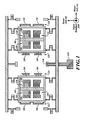
- FIGURE 1 illustrates a Micro-Electro-Mechanical Systems (MEMS) capacitance modulation device embodiment
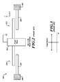
- FIGURE 2 illustrates sense electrodes of a conventional MEMS gyroscope having sense capacitance independent of time
- FIGURE 3 illustrates capacitance as a function of motor displacement distance ( ⁇ x) of the prior art MEMS gyroscope of FIGURE 2 ;
- FIGURES 4 , 6 , 8 , 10 , and 12 illustrate gaps between the electrodes that vary with motor displacement
- FIGURES 5 , 7 , 9 , 11 , and 13 illustrate capacitance as a function of motor displacement distance ( ⁇ x) of the embodiments illustrated in FIGURES 4 , 6 , 8 , 10 , and 12 , respectively;
- FIGURES 14a , 14b , and 14c illustrate a MEMS gyroscope sensor with four sense capacitances.
- FIGURE 1 illustrates an exemplary Micro-Electro-Mechanical Systems (MEMS) capacitance modulation device 100.
- the exemplary embodiment of the MEMS capacitance modulation device 100 has a first vibrating mass 102, a second vibrating mass 104, one or more left motors 106, a top center motor pickoff 108, a bottom center motor pickoff 109, one or more right motors 110, a left comb structure 112, a first center comb structure 114, a second center comb structure 116, a right comb structure 118, left sense electrodes 120, right sense electrodes 122, and an output electrode 124 coupled to one or more anchor points 126.
- MEMS capacitance modulation device 100 has a first vibrating mass 102, a second vibrating mass 104, one or more left motors 106, a top center motor pickoff 108, a bottom center motor pickoff 109, one or more right motors 110, a left comb structure 112, a first center comb structure 114,
- the left motor 106 is capacitively coupled to the first vibrating mass 102 via the left comb structure 112.
- the right motor 110 is capacitively coupled to the second vibrating mass 104 via the right comb structure 118.
- the center motor pickoffs 108, 109 are capacitively coupled to the first vibrating mass 102 via the first center comb structure 114.
- the center motor pickoffs 108, 109 are capacitively coupled to the second vibrating mass 104 via the second center comb structure 116.
- the left motor 106 and the right motor 110 are driven with signals to impart a vibrating motion at a known frequency to the first vibrating mass 102 and the second vibrating mass 104, hereinafter referred to as the motor frequency.
- the center motor pickoffs 108, 109 are biased with DC voltages, so that motion of the proof masses along the x-axis produces AC electrical currents which are input to electronics controlling the signals applied to the motor combs.
- the sense electrodes 120, 122 are capacitively coupled to the first and second vibrating masses 102, 104, respectively, by a plurality of comb finger pairs 128. Each comb finger pair 128 has one comb finger attached to the vibrating mass and another comb finger attached to a sense electrode.
- Sense electrodes 120, 122 are coupled to anchors 130.
- comb finger pairs 128 are separated from other comb finger pairs by a predefined distance.
- the comb finger pairs are arranged so that each pair has a corresponding pair such that the two pairs have mirror symmetry about the motor axis shown in FIGURE 1 .
- Other configurations for comb structures may be used in alternative embodiments of the MEMS capacitance modulation device 100.
- Embodiments of the MEMS capacitance modulation device 100 employ various configurations in the structure of the comb finger pairs 128, as described in greater detail below.
- the structures of the comb finger pairs allow the capacitance of a comb finger pair 128 to vary with the displacement of the vibrating mass along the motor axis.
- Embodiments of the MEMS capacitance modulation device 100 produce parametric amplification with the phase of the pump force precisely synchronized with the phase of the motor motion of the sensor mechanism. In some embodiments, this is achieved by designing the sense electrodes 120, 122 so that motor motion produces a modulation of the sense capacitance at twice the motor frequency, resulting in a parametric pump force at twice the motor frequency, due to modulation of the electrostatic force on the sense mode.
- the phase of the parametric pump force is precisely synchronized with the motor motion of the proof masses, because the parametric pump force is produced by the motor motion of the proof masses.
- F y (t) can be a pump force which provides parametric amplification of the mechanical response of the proof masses to an input force (e.g., Coriolis force).
- F y (t) can be a pump force which provides suppression of the response to the quadrature-phase force.
- the amplified mechanical response is produced in a manner similar to that described in U.S. patent 6,715,353 , except that the pump force in the present invention is produced by modulation of the sense capacitance.
- the pump force described in U.S. patent 6,715,353 was produced by applying AC voltage to the sense capacitance, so that Vbias 2 is modulated at twice the motor frequency, with dC/dy independent of time.
- FIGURE 2 illustrates an assembly 200 containing two pairs of sense comb fingers that are part of a conventional prior art MEMS gyroscope, with one member of each pair being attached to vibrating proof mass 202.
- the total capacitance of the two comb finger pairs is independent of the displacement distance of the vibrating mass 202 along the x-axis.
- the assembly 200 has a proof mass 202, a left sense electrode comb finger 204, and a right sense electrode comb finger 206.
- the left sense electrode comb finger 204 and the right sense electrode comb finger 206 are attached to their respective sense electrodes 208.
- the sense electrodes 208 are secured to anchors attached to the substrate (not shown).
- left sense electrode comb finger 204 and the right sense electrode comb finger 206 are capacitively coupled to the comb fingers 210, 212, respectively, of the proof mass 202.
- a motor motion induced to the proof mass 202 along the x-axis does not cause a variance in the capacitance between the sense electrodes comb fingers 204, 206 and the comb fingers 210, 212 of the proof mass 202.
- FIGURE 3 illustrates capacitance as a function of motor displacement distance ( ⁇ x) of the prior art assembly 200.
- the proof mass motor motion is along the x-axis. Motor motion produces equal and opposite changes in the left and right capacitances of the sense electrodes comb fingers 204, 206 and the comb fingers 210, 212. Accordingly, the total capacitance is independent of motor motion.
- FIGURE 4 illustrates an assembly 400 containing two instances of an exemplary embodiment of a sense comb finger pair 128 that provides modulation of the sense capacitance.
- Assembly 400 may be part of a MEMS gyroscope.
- the assembly 400 has a proof mass 402, a left sense electrode comb finger 404 and a right sense electrode comb finger 406.
- the proof mass 402 has a left proof mass comb finger 408 that provides capacitive coupling to the corresponding sense electrode comb finger 404 at gap 410.
- the proof mass 402 has a right proof mass comb finger 412 that provides capacitive coupling to the corresponding sense electrode comb finger 406 at gap 414.
- the sense electrode comb fingers 404 and 406 are attached to their respective sense electrodes 416.
- the sense electrodes 416 are secured to anchors attached to the substrate (not shown).
- the sense electrode comb fingers 404, 406 are defined by an end portion 418 and an attaching portion 420 which secures them to their respective sense electrodes 416.
- the proof mass comb fingers 408, 412 are defined by an end portion 422 and an attaching portion 424 which secures the proof mass comb fingers 408, 412 to the proof mass body 426.
- the gaps 410, 414 define the capacitive coupling (capacitance) between the sense electrode comb fingers 404, 406 and the proof mass comb fingers 408, 412.
- the comb finger end portion 418 has a width that is greater than the width of the comb finger attaching portion 420.
- the proof mass comb fingers 408, 412 have an end portion 422 that is wider than a portion 424 attached to the body 426 of the proof mass 402.
- the comb finger portions 418 and 420 are the same width while the comb finger end portion 422 is wider than the comb finger portion 424.
- the differences in the width of the comb finger portions 418 and 420, and/or the comb finger portions 422 and 424 causes a change in the gaps 410, 414 as the motor motion is induced to the proof mass 402.
- the sense electrode comb fingers 404, 406 have capacitance modulated at twice the motor frequency.
- the derivative of said capacitance with respect to displacement along the illustrated y-axis also changes with motor displacement ⁇ x.
- the electrostatic force along the illustrated y-axis given by equation 1, varies with x-axis displacement of the proof mass.
- the capacitance is configured to decrease with positive and negative motor displacement distance ( ⁇ x), in accordance with FIGURE 5 .
- FIGURE 6 illustrates an assembly 600 containing two instances of an exemplary embodiment of a sense comb finger pair 128 that provides modulation of the sense capacitance.
- Assembly 600 may be part of a MEMS gyroscope.
- the assembly 600 has a proof mass 602, a left sense electrode comb finger 604 and a right sense electrode comb finger 606.
- the proof mass 602 has a left comb finger 608 that provides capacitive coupling to the left sense electrode comb finger 604 at gap 610.
- the proof mass 602 has a right comb finger 612 that provides capacitive coupling to the right sense electrode comb finger 606 at gap 614.
- the sense electrode comb fingers 604 and 606 are attached to their respective sense electrodes 616.
- the sense electrodes 616 are secured to anchors attached to the substrate (not shown).
- the sense electrode comb fingers 604, 606 are defined by an end portion 618 and an attaching portion 620 which secures the sense electrode comb fingers 604, 606 to their respective sense electrodes 616.
- the proof mass comb fingers 608, 612 are defined by an end portion 622 and an attaching portion 624 which secures the proof mass comb fingers 608, 612 to the proof mass body 626.
- the gaps 610, 614 define the capacitive coupling (capacitance) between the sense electrode comb fingers 604, 606 and the proof mass comb fingers 608, 612.
- the width of end portion 618 is smaller than the width of portion 620.
- the proof mass comb fingers 608, 612 have an end portion 622 with a width that is less than the width of a portion 624 attached to the body 626 of the proof mass 602.
- the portions 618 and 620 are the same width while the end portion 622 has a width less than the portion 624.
- the differences in the widths of the portions 618 and 620, and/or the portions 622 and 624 cause a change in the capacitance of the gaps 610, 614 as the motor motion is induced to the proof mass 602.
- the comb fingers 604, 606 have capacitance modulated at twice the motor frequency. Accordingly, capacitance increases with motor displacement. The capacitance is illustrated as a function of motor displacement in FIGURE 7 .
- the derivative of said capacitance with respect to displacement along the illustrated y-axis also changes with motor displacement ⁇ x.
- the electrostatic force along the illustrated y-axis given by equation 1, varies with x-axis displacement of the proof mass.
- the capacitance is configured to increase with positive and negative motor displacement distance ( ⁇ x), in accordance with FIGURE 7 .
- FIGURE 8 illustrates an assembly 800 containing two instances of an exemplary embodiment of a sense comb finger pair 128 that provides modulation of the sense capacitance.
- Assembly 800 may be part of a MEMS gyroscope.
- the assembly 800 has a proof mass 802, a left sense electrode comb finger 804 and a right sense electrode comb finger 806.
- the proof mass 802 has a left comb finger 808 that provides capacitive coupling to the left sense electrode comb finger 804 at gap 810.
- the proof mass 802 has a right comb finger 812 that provides capacitive coupling to the right sense electrode comb finger 806 at gap 814.
- the sense electrode comb fingers 804 and 806 are attached to their respective sense electrodes 816.
- the sense electrodes 816 are secured to anchors attached to the substrate (not shown).
- the sense electrode comb fingers 804, 806 are defined by an end portion 818 and an attaching portion 820 which secures the sense electrode comb fingers 804, 806 to their respective sense electrodes 816.
- the proof mass comb fingers 808, 812 are defined by an end portion 822 and an attaching portion 824 which secures the proof mass comb fingers 808, 812 to the proof mass body 826.
- the gaps 810, 814 define the capacitive coupling (capacitance) between the sense electrode comb fingers 804, 806 and the proof mass comb fingers 808, 812.
- the sense electrode comb fingers 804, 806 have a corrugated end portion 818 and a non-corrugated attaching portion 820.
- the proof mass comb fingers 808, 812 have an end portion 822 that is corrugated and a non-corrugated attaching portion 824.
- the end portions 822 are corrugated while the portions 818 are non-corrugated.
- the corrugation of the portion 818, and/or the portions 822 cause a change in the capacitance gaps 810, 814 as the motor motion is induced to the proof mass 802.
- the sense electrodes 816 have capacitance modulated at twice the motor frequency. Accordingly, capacitance increases with motor displacement. The capacitance is illustrated as a function of motor displacement in FIGURE 9 .
- the derivative of the capacitance with respect to displacement along the illustrated y-axis also changes with motor displacement ⁇ x.
- the electrostatic force along the illustrated y-axis given by equation 1, varies with x-axis displacement of the proof mass.
- the capacitance is configured to increase with positive and negative motor displacement distance ( ⁇ x), in accordance with FIGURE 9 .
- FIGURE 10 illustrates an assembly 1000 containing two instances of an exemplary embodiment of a sense comb finger pair 128 that provides modulation of the sense capacitance.
- Assembly 1000 may be part of a MEMS gyroscope.
- the assembly 1000 has a proof mass 1002, a left sense electrode comb finger 1004 and a right sense electrode comb finger 1006.
- the proof mass 1002 has a left comb finger 1008 that provides capacitive coupling to the left sense electrode comb finger 1004 at gap 1010.
- the proof mass 1002 has a right comb finger 1012 that provides capacitive coupling to the right sense electrode comb finger 1006 at gap 1014.
- the sense electrode comb fingers 1004 and 1006 are attached to their respective sense electrodes 1016.
- the sense electrodes 1016 are secured to anchors attached to the substrate (not shown).
- the sense electrode comb fingers 1004, 1006 are defined by an end portion 1018 and an attaching portion 1020 which secures the sense electrode comb fingers 1004, 1006 to their respective sense electrodes 1016.
- the proof mass comb fingers 1008, 1012 are defined by an end portion 1022 and an attaching portion 1024 which secures the proof mass comb fingers 1008, 1012 to the proof mass body 1026.
- the gaps 1010, 1014 define the capacitive coupling (capacitance) between the sense electrode comb fingers 1004, 1006 and the proof mass comb fingers 1008, 1012.
- the sense electrode comb fingers 1004, 1006 have a corrugated end portion 1018 and a non-corrugated attaching portion 1020.
- the corrugations of comb finger 1004 oppose the corrugations of comb finger 1008, and the corrugations of comb finger 1006 oppose the corrugations of comb finger 1012.
- the sense electrodes 1016 have capacitance modulated at twice the motor frequency. Accordingly, capacitance decreases with motor displacement.
- the capacitance is illustrated as a function of motor displacement in FIGURE 11 .
- the derivative of said capacitance with respect to displacement along the illustrated y-axis also changes with motor displacement ⁇ x.
- the electrostatic force along the illustrated y-axis given by equation 1, varies with x-axis displacement of the proof mass.
- the capacitance is configured to decrease with positive and negative motor displacement distance ( ⁇ x), in accordance with FIGURE 11 .
- FIGURE 12 illustrates an assembly 1200 containing two instances of an exemplary embodiment of a sense comb finger pair 128 that provides modulation of the sense capacitance.
- Assembly 1200 may be part of a MEMS gyroscope.
- the assembly 1200 has a proof mass 1202, a left sense electrode comb finger 1204 and a right sense electrode comb finger 1206.
- the proof mass 1202 has a left comb finger 1208 that provides capacitive coupling to the left sense electrode comb finger 1204 at gap 1210.
- the proof mass 1202 has a right comb finger 1212 that provides capacitive coupling to the right sense electrode comb finger 1206 at gap 1214.
- the sense electrode comb fingers 1204 and 1206 are attached to their respective sense electrodes 1216.
- the sense electrodes 1216 are secured to anchors attached to the substrate (not shown).
- the sense electrode comb fingers 1204, 1206 are defined by an end portion 1218 and an attaching portion 1220 which secures the sense electrode comb fingers 1204, 1206 to their respective sense electrodes 1216.
- the proof mass comb fingers 1208, 1212 are defined by an end portion 1222 and an attaching portion 1224 which secures the proof mass comb fingers 1208, 1212 to the proof mass body 1226.
- the gaps 1210, 1214 define the capacitive coupling (capacitance) between the sense electrode comb fingers 1204, 1206 and the proof mass comb fingers 1208, 1212.
- FIGURE 12 illustrates that x-axis motion of the sense electrode comb fingers 1204, 1206 provides modulation of the capacitance gaps 1210, 1214.
- the sense electrode comb fingers 1204, 1206 and the proof mass comb fingers 1208, 1212 are tilted at a shallow angle with respect to the x-axis, so that motor motion of the proof mass 1202 along the x-axis causes the capacitance gaps 1210, 1214 to increase on one side of the proof mass 1202 and decrease on the other side in a non-linear fashion. Since the capacitance is inversely proportional to the gap, the total capacitance is increased by the x-axis displacement.
- the non-linear dependence of capacitance on the gaps 1210, 1214 causes the tilted sense electrodes to provide capacitance modulation with an approximately parabolic dependence of capacitance on motor displacement, as illustrated in Figure 11 .
- capacitance is illustrated as a function of motor displacement, for the assembly of Figure 12 .
- the capacitance is a non-linear function of the motor displacement distance ( ⁇ x) along the illustrated x-axis.
- the derivative of said capacitance with respect to displacement along the illustrated y-axis also changes with motor displacement ⁇ x.
- the non-linear capacitance as a function of x-axis displacement of the proof mass 1202 in assembly 1200 may provide more effective parametric amplification than the electrodes of the assemblies shown in FIGURES 4 , 6 , and/or 8, since the frequency component of the capacitance modulation at twice the motor frequency is larger when the capacitance is an approximately parabolic function of motor displacement than when it is proportional to the absolute value of motor displacement, for equal amplitudes of oscillatory motor displacement.
- the configurations of FIGURES 4 , 6 , and/or 8 may be preferable for some situations, because the tilted electrodes illustrated in FIGURE 12 may be impractical and/or difficult to make when the comb fingers are very long.
- the modulation of capacitance produced by the mating comb fingers of the comb finger pairs 128 illustrated in FIGURES 4 , 6 , 8 , 10 and/or 12 also produces modulation of the first and second derivatives of capacitance with respect to displacement along the y-axis.
- the modulation of these derivatives is the origin of the parametric amplification effects that are the subject of the various embodiments.
- Modulating the sense capacitance affects the MEMS gyro sensor's mechanical gain (transfer function between input force and proof mass displacement) as well as its electrical gain (transfer function between proof mass displacement and electrical output signal). The effect on mechanical gain is described hereinbelow.
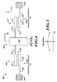
- FIGURES 14a , 14b , and 14c show various embodiments of a MEMS gyroscope 1400 with four sense capacitances C +1 (x,y 1 ), C -1 (x,y 1 ), C +2 (x,y 2 ), and C -2 (x,y 2 ), which may be modulated at twice the motor frequency in an exemplary embodiment.
- FIGURES 14a , 14b , and 14c do not show the detailed capacitor shape necessary for the modulation.
- FIGURES 14a , 14b , and 14c show three methods of applying sense bias voltage to MEMS gyroscope 1400, and the corresponding methods for connecting a charge amplifier in order to produce an output voltage proportional to the rotation rate.
- FIGURE 14a illustrates two polarities of sense bias voltage on the sense plates, and a single-ended charge amplifier 1402 whose input is AC-coupled to the sense plates.
- the sense capacitances are biased with DC bias voltages V + (positive) and V- (negative), which in some embodiments may be of equal magnitude and opposite polarity.
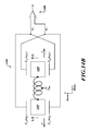
- FIGURE 14b illustrates a single polarity of sense bias voltage, V bias, on the proof masses 1404, 1406, and a differential charge amplifier 1408 whose inputs are DC-coupled to the sense plates.
- the differential charge amplifier 1408 is typically constructed such that its inputs are maintained at virtual ground. As a result, the voltage on the sense plates is maintained at virtual ground.
- FIGURE 14c illustrates two polarities of sense bias voltage on the sense plates, and a single-ended charge amplifier 1410 whose input is DC-coupled to the proof masses.
- the sense capacitances are biased with DC bias voltages V + (positive) and V - (negative), which in some embodiments may be of equal magnitude and opposite polarity.
- the x-axis displacements of the two proof masses 1404, 1406 have the same magnitude (labeled as "x" in FIGURES 14a , 14b , and 14c ), but opposite directions.
- Rotation about an axis orthogonal to the motor axis (x axis) and the sense axis (y axis) produces Coriolis forces on the proof masses along the sense axis.
- the resulting proof mass displacements change the four sense capacitances, producing time-varying charges q + (t) and q - (t) on the sense capacitances, which are inputs to the charge amplifiers shown in FIGURES 14a , 14b , or 14c .
- sense mode motion is defined by equation (3) as: y S t ⁇ y 1 - y 2 2 .
- the first and second time derivatives of y S (t) are ⁇ S and ⁇ S
- ⁇ is the driven frequency of motor motion along the x-axis
- ⁇ is a phase factor.
- the first term on the right hand side of equation (2) is the differential electrostatic force produced by the sense capacitances.
- the displacements y 1 (t) and y 2 (t) are typically small. Therefore, it is useful to expand the capacitances in Taylor series in y 1 (t) and y 2 (t), and ignore terms beyond second order.
- the motor motion modulates C" +1 (x,0) as a function of time.
- the modulation can be expressed as a Fourier series consisting of harmonics of twice the motor frequency ⁇ , as defined by equation (7):
- the reflection symmetry of the sense capacitor along the x-axis causes odd harmonics of the motor frequency to be zero, as well as requiring that the coefficients of sin(2n ⁇ t) are zero in the Fourier series of the sense capacitance.
- Equation (8) has the form of the well-known Mathieu equation. It shows that the sense resonant frequency is modulated at twice the motor frequency, due to the modulation of C +1 "(x,0) by the motor motion of the proof masses. This modulation of the sense frequency produces parametric amplification in the embodiments.
- the sense mode response y S (t) given by solving equation (8) is primarily at the motor frequency ⁇ , because the driving force F(t) is at frequency ⁇ , which is close to the sense resonant frequency ⁇ s , where the mechanical response is large. Terms at other frequencies are far from the sense resonant frequency, so they do not produce a large contribution to y S (t). This is also the reason that equation (8) excludes terms in C" +1 (x,0) with frequency higher than 2 ⁇ .
- C +1 (x,0), and C' +1 (x,0), its first derivative with respect to y 1 can be written as Fourier series in a manner similar to equation (7) for C" +1 (x,0) as defined by equations (14) and (15) as:
- equation (16) terms with frequency higher than 2 ⁇ are neglected.
- the readout electronics of the MEMS gyroscope uses phase-sensitive detection to reject signals at frequencies other than the desired motor frequency ⁇ , so only the motor frequency component of the sensor output is of interest.
- the first three terms on the right hand side of equation (16) do not contribute to the gyro output, because the configuration of bias voltages, combined with the choice of a single-ended or differential charge amplifier in the embodiments of FIGURES 14a , 14b , and 14c , is designed to null the contribution of these terms at the charge amplifier output.
- Equations (17) and (18) show that the amplitudes of the sense capacitance charges are dependent on the phase of the sense mode displacement y s (t).
- the electrical gain of the sensor is phase-dependent, so the electrical gain for a Coriolis-phase signal can be larger than that of a quadrature-phase signal.
- An alternative to modulating the sense capacitance is to provide a set of auxiliary electrodes whose capacitance is modulated by the motor motion. If a DC bias voltage is applied to these auxiliary electrodes, and the second derivative of their capacitance with respect to sense axis displacement is modulated by motor motion, then these electrodes can modulate the sense frequency and produce parametric amplification.
- the parametric amplification is produced by modifying the mechanical gain of the sensor, as expressed by equation (11).
- the electrical gain of the sensor is not modified, since the electrical gain is determined by the sense electrodes.
- the use of auxiliary electrodes may provide greater flexibility in designing the mechanical and electrical gains of the sensor independently.
- comb finger pairs were described in the context of an out-of-plane MEMS gyroscope. Embodiments may also be implemented in an in-plane MEMS gyroscope, in a MEMS accelerometer, or other MEMS devices that employ comb pairs operated to generate a sensed capacitance. Furthermore, alternative embodiments of a MEMS capacitance modulation device 100 may have the sense electrodes, proof masses, and/or their respective comb fingers arranged differently, or may include more or less, than the exemplary embodiments described and/or illustrated herein.
Landscapes
- Engineering & Computer Science (AREA)
- Physics & Mathematics (AREA)
- General Physics & Mathematics (AREA)
- Radar, Positioning & Navigation (AREA)
- Remote Sensing (AREA)
- Signal Processing (AREA)
- Gyroscopes (AREA)
Applications Claiming Priority (2)
| Application Number | Priority Date | Filing Date | Title |
|---|---|---|---|
| US1304107P | 2007-12-12 | 2007-12-12 | |
| US12/113,093 US8037757B2 (en) | 2007-12-12 | 2008-04-30 | Parametric amplification of a MEMS gyroscope by capacitance modulation |
Publications (3)
| Publication Number | Publication Date |
|---|---|
| EP2071284A2 true EP2071284A2 (fr) | 2009-06-17 |
| EP2071284A3 EP2071284A3 (fr) | 2014-08-06 |
| EP2071284B1 EP2071284B1 (fr) | 2017-08-02 |
Family
ID=40451363
Family Applications (1)
| Application Number | Title | Priority Date | Filing Date |
|---|---|---|---|
| EP08166391.6A Active EP2071284B1 (fr) | 2007-12-12 | 2008-10-10 | Amplification paramétrique d'un gyroscope MEMS par modulation de la capacité |
Country Status (3)
| Country | Link |
|---|---|
| US (1) | US8037757B2 (fr) |
| EP (1) | EP2071284B1 (fr) |
| JP (1) | JP5349891B2 (fr) |
Cited By (4)
| Publication number | Priority date | Publication date | Assignee | Title |
|---|---|---|---|---|
| WO2015063727A1 (fr) * | 2013-11-01 | 2015-05-07 | Murata Manufacturing Co., Ltd. | Compensation de quadrature améliorée |
| CN108535505A (zh) * | 2017-03-06 | 2018-09-14 | 恩智浦美国有限公司 | 具有平面内正交补偿的mems装置 |
| EP2743639B1 (fr) * | 2011-08-09 | 2018-09-19 | Toyota Jidosha Kabushiki Kaisha | Structure d'électrode de surveillance de déplacement |
| CN109399549A (zh) * | 2018-10-15 | 2019-03-01 | 北京航天控制仪器研究所 | 一种微机械静电驱动的直线型梳齿结构 |
Families Citing this family (30)
| Publication number | Priority date | Publication date | Assignee | Title |
|---|---|---|---|---|
| JP5133814B2 (ja) * | 2008-08-13 | 2013-01-30 | ラピスセミコンダクタ株式会社 | 可変容量素子 |
| IT1391972B1 (it) | 2008-11-26 | 2012-02-02 | St Microelectronics Rousset | Giroscopio microelettromeccanico con movimento di azionamento rotatorio e migliorate caratteristiche elettriche |
| IT1392741B1 (it) | 2008-12-23 | 2012-03-16 | St Microelectronics Rousset | Giroscopio microelettromeccanico con migliorata reiezione di disturbi di accelerazione |
| IT1394007B1 (it) | 2009-05-11 | 2012-05-17 | St Microelectronics Rousset | Struttura microelettromeccanica con reiezione migliorata di disturbi di accelerazione |
| ITTO20091042A1 (it) | 2009-12-24 | 2011-06-25 | St Microelectronics Srl | Giroscopio integrato microelettromeccanico con migliorata struttura di azionamento |
| US8584522B2 (en) | 2010-04-30 | 2013-11-19 | Qualcomm Mems Technologies, Inc. | Micromachined piezoelectric x-axis gyroscope |
| JP5442866B2 (ja) * | 2010-07-06 | 2014-03-12 | 日立オートモティブシステムズ株式会社 | 慣性センサ |
| ITTO20110688A1 (it) * | 2011-07-28 | 2013-01-29 | St Microelectronics Srl | Giroscopio microelettromeccanico con funzione di autocalibrazione e metodo di calibrazione di un giroscopio microelettromeccanico |
| JP5621936B2 (ja) * | 2011-08-09 | 2014-11-12 | トヨタ自動車株式会社 | 変位量モニタ電極の構造 |
| ITTO20110806A1 (it) * | 2011-09-12 | 2013-03-13 | St Microelectronics Srl | Dispositivo microelettromeccanico integrante un giroscopio e un accelerometro |
| TWI453371B (zh) | 2011-12-30 | 2014-09-21 | Ind Tech Res Inst | 一種具振盪模組的微機電系統裝置 |
| DE102012200929B4 (de) * | 2012-01-23 | 2020-10-01 | Robert Bosch Gmbh | Mikromechanische Struktur und Verfahren zur Herstellung einer mikromechanischen Struktur |
| CN104662396A (zh) * | 2012-04-30 | 2015-05-27 | 惠普发展公司,有限责任合伙企业 | 基于从振动数据识别的事件的通知 |
| CN104395842A (zh) * | 2012-04-30 | 2015-03-04 | 惠普发展公司,有限责任合伙企业 | 基于用户敲击的命令的控制信号 |
| US9310202B2 (en) * | 2012-07-09 | 2016-04-12 | Freescale Semiconductor, Inc. | Angular rate sensor with quadrature error compensation |
| WO2014203903A1 (fr) * | 2013-06-19 | 2014-12-24 | ヤマハ株式会社 | Module de réglage de la fréquence de résonance |
| GB201313389D0 (en) | 2013-07-26 | 2013-09-11 | Atlantic Inertial Systems Ltd | Signal processing |
| US9404747B2 (en) | 2013-10-30 | 2016-08-02 | Stmicroelectroncs S.R.L. | Microelectromechanical gyroscope with compensation of quadrature error drift |
| WO2015194479A1 (fr) * | 2014-06-18 | 2015-12-23 | 株式会社村田製作所 | Module de réglage de fréquence de résonance et capteur mems |
| JP2016099208A (ja) * | 2014-11-20 | 2016-05-30 | セイコーエプソン株式会社 | ジャイロセンサー、電子機器および移動体 |
| US10020792B2 (en) | 2015-09-24 | 2018-07-10 | Google Llc | Phase shifter |
| US20170138734A1 (en) * | 2015-11-16 | 2017-05-18 | Freescale Semiconductor, Inc. | Mems device with capacitance enhancement on quadrature compensation electrode |
| RU173867U1 (ru) * | 2016-12-15 | 2017-09-15 | федеральное государственное автономное образовательное учреждение высшего образования "Санкт-Петербургский политехнический университет Петра Великого" (ФГАОУ ВО "СПбПУ") | Вибрационный гироскоп LL-типа |
| RU179133U1 (ru) * | 2017-12-27 | 2018-04-28 | федеральное государственное автономное образовательное учреждение высшего образования "Санкт-Петербургский политехнический университет Петра Великого" (ФГАОУ ВО "СПбПУ") | Вибрационный гироскоп LL-типа |
| US12253391B2 (en) | 2018-05-24 | 2025-03-18 | The Research Foundation For The State University Of New York | Multielectrode capacitive sensor without pull-in risk |
| JP7225817B2 (ja) * | 2019-01-17 | 2023-02-21 | セイコーエプソン株式会社 | 角速度センサー、慣性計測装置、電子機器および移動体 |
| US12012327B2 (en) | 2020-03-12 | 2024-06-18 | Honeywell International Inc. | Methods for vibration immunity to suppress bias errors in sensor devices |
| CN112129278B (zh) * | 2020-09-15 | 2022-08-19 | 浙江大学 | 可减小由电容边缘效应导致的电容-位移之间的非线性的栅结构 |
| IT202100024644A1 (it) | 2021-09-27 | 2023-03-27 | St Microelectronics Srl | Circuito di controllo di un giroscopio mems, giroscopio mems e metodo di controllo |
| CN118114506B (zh) * | 2024-04-28 | 2024-07-12 | 广东工业大学 | 一种mems陀螺电耦合和机械耦合表征建模方法 |
Citations (2)
| Publication number | Priority date | Publication date | Assignee | Title |
|---|---|---|---|---|
| US1304108A (en) | 1917-07-23 | 1919-05-20 | Louis Jacques Simon | Process for the manufacture of monochloracetic acid. |
| US6715353B2 (en) | 2002-04-25 | 2004-04-06 | Honeywell International, Inc. | MEMS gyroscope with parametric gain |
Family Cites Families (10)
| Publication number | Priority date | Publication date | Assignee | Title |
|---|---|---|---|---|
| JP2000206142A (ja) * | 1998-11-13 | 2000-07-28 | Denso Corp | 半導体力学量センサおよびその製造方法 |
| US6257059B1 (en) * | 1999-09-24 | 2001-07-10 | The Charles Stark Draper Laboratory, Inc. | Microfabricated tuning fork gyroscope and associated three-axis inertial measurement system to sense out-of-plane rotation |
| JP2001141462A (ja) * | 1999-11-10 | 2001-05-25 | Alps Electric Co Ltd | ジャイロスコープおよびこれを用いた入力装置 |
| JP2001227954A (ja) * | 2000-02-15 | 2001-08-24 | Toyota Motor Corp | 物理量検出装置 |
| JP2002040045A (ja) * | 2000-07-21 | 2002-02-06 | Denso Corp | 力学量センサ |
| US6611168B1 (en) * | 2001-12-19 | 2003-08-26 | Analog Devices, Inc. | Differential parametric amplifier with physically-coupled electrically-isolated micromachined structures |
| JP4063057B2 (ja) * | 2002-11-20 | 2008-03-19 | 株式会社デンソー | 容量式加速度センサ |
| JP2004233088A (ja) * | 2003-01-28 | 2004-08-19 | Murata Mfg Co Ltd | 静電可動機構、共振型装置および角速度センサ |
| US7036373B2 (en) * | 2004-06-29 | 2006-05-02 | Honeywell International, Inc. | MEMS gyroscope with horizontally oriented drive electrodes |
| US7444869B2 (en) * | 2006-06-29 | 2008-11-04 | Honeywell International Inc. | Force rebalancing and parametric amplification of MEMS inertial sensors |
-
2008
- 2008-04-30 US US12/113,093 patent/US8037757B2/en active Active
- 2008-10-10 EP EP08166391.6A patent/EP2071284B1/fr active Active
- 2008-10-14 JP JP2008265331A patent/JP5349891B2/ja not_active Expired - Fee Related
Patent Citations (2)
| Publication number | Priority date | Publication date | Assignee | Title |
|---|---|---|---|---|
| US1304108A (en) | 1917-07-23 | 1919-05-20 | Louis Jacques Simon | Process for the manufacture of monochloracetic acid. |
| US6715353B2 (en) | 2002-04-25 | 2004-04-06 | Honeywell International, Inc. | MEMS gyroscope with parametric gain |
Non-Patent Citations (1)
| Title |
|---|
| L. A. OROPEZA-RAMOS; K. L. TURNER: "Parametric Resonance Amplification in a MEM Gyroscope", PROCEEDINGS OF THE 2005 IEEE SENSORS CONFERENCE, 1 December 2005 (2005-12-01), pages 660 - 663 |
Cited By (9)
| Publication number | Priority date | Publication date | Assignee | Title |
|---|---|---|---|---|
| EP2743639B1 (fr) * | 2011-08-09 | 2018-09-19 | Toyota Jidosha Kabushiki Kaisha | Structure d'électrode de surveillance de déplacement |
| WO2015063727A1 (fr) * | 2013-11-01 | 2015-05-07 | Murata Manufacturing Co., Ltd. | Compensation de quadrature améliorée |
| CN105683709A (zh) * | 2013-11-01 | 2016-06-15 | 株式会社村田制作所 | 改进的正交补偿 |
| US9897447B2 (en) | 2013-11-01 | 2018-02-20 | Murata Manufacturing Co., Ltd. | Quadrature compensation |
| CN105683709B (zh) * | 2013-11-01 | 2019-11-12 | 株式会社村田制作所 | 微机电传感器设备 |
| CN108535505A (zh) * | 2017-03-06 | 2018-09-14 | 恩智浦美国有限公司 | 具有平面内正交补偿的mems装置 |
| EP3372956A3 (fr) * | 2017-03-06 | 2019-05-15 | NXP USA, Inc. | Dispositif mems doté d'une compensation de quadrature dans le plan |
| CN109399549A (zh) * | 2018-10-15 | 2019-03-01 | 北京航天控制仪器研究所 | 一种微机械静电驱动的直线型梳齿结构 |
| CN109399549B (zh) * | 2018-10-15 | 2021-06-11 | 北京航天控制仪器研究所 | 一种微机械静电驱动的直线型梳齿结构 |
Also Published As
| Publication number | Publication date |
|---|---|
| JP5349891B2 (ja) | 2013-11-20 |
| EP2071284B1 (fr) | 2017-08-02 |
| EP2071284A3 (fr) | 2014-08-06 |
| US20090320591A1 (en) | 2009-12-31 |
| US8037757B2 (en) | 2011-10-18 |
| JP2009271052A (ja) | 2009-11-19 |
Similar Documents
| Publication | Publication Date | Title |
|---|---|---|
| EP2071284B1 (fr) | Amplification paramétrique d'un gyroscope MEMS par modulation de la capacité | |
| US6715353B2 (en) | MEMS gyroscope with parametric gain | |
| US7051590B1 (en) | Structure for attenuation or cancellation of quadrature error | |
| KR101166866B1 (ko) | 수평으로 배향된 구동 전극을 구비한 mems자이로스코프 | |
| US6621279B2 (en) | Drive feedthrough nulling system | |
| US6230563B1 (en) | Dual-mass vibratory rate gyroscope with suppressed translational acceleration response and quadrature-error correction capability | |
| US9958271B2 (en) | Configuration to reduce non-linear motion | |
| JP3785261B2 (ja) | マイクロアクチュエータの相補型静電駆動装置 | |
| US6250156B1 (en) | Dual-mass micromachined vibratory rate gyroscope | |
| US7444869B2 (en) | Force rebalancing and parametric amplification of MEMS inertial sensors | |
| US9897447B2 (en) | Quadrature compensation | |
| US10330476B2 (en) | Angular rate sensor with in-phase motion suppression structure | |
| US7100446B1 (en) | Distributed-mass micromachined gyroscopes operated with drive-mode bandwidth enhancement | |
| US20030084722A1 (en) | Vibration-type micro-gyroscope | |
| US10753744B2 (en) | MEMS out of plane actuator | |
| JPS62217115A (ja) | ジヤイロ装置 | |
| EP3184962A1 (fr) | Dispositif mems avec amélioration des capacité sur l'électrode de compensation de quadrature | |
| KR101433590B1 (ko) | 커패시턴스 변조에 의한 mems 자이로스코프의 파라미터증폭 | |
| Evstifeev et al. | MEMS RR-type gyro with a moving electrode | |
| Song et al. | Design and performance test of an in-plane gimbaled silicon gyroscope | |
| JP2002013932A (ja) | 角速度センサの駆動方法 |
Legal Events
| Date | Code | Title | Description |
|---|---|---|---|
| PUAI | Public reference made under article 153(3) epc to a published international application that has entered the european phase |
Free format text: ORIGINAL CODE: 0009012 |
|
| 17P | Request for examination filed |
Effective date: 20081010 |
|
| AK | Designated contracting states |
Kind code of ref document: A2 Designated state(s): AT BE BG CH CY CZ DE DK EE ES FI FR GB GR HR HU IE IS IT LI LT LU LV MC MT NL NO PL PT RO SE SI SK TR |
|
| AX | Request for extension of the european patent |
Extension state: AL BA MK RS |
|
| PUAL | Search report despatched |
Free format text: ORIGINAL CODE: 0009013 |
|
| RIC1 | Information provided on ipc code assigned before grant |
Ipc: G01C 19/56 20120101AFI20140603BHEP |
|
| AK | Designated contracting states |
Kind code of ref document: A3 Designated state(s): AT BE BG CH CY CZ DE DK EE ES FI FR GB GR HR HU IE IS IT LI LT LU LV MC MT NL NO PL PT RO SE SI SK TR |
|
| AX | Request for extension of the european patent |
Extension state: AL BA MK RS |
|
| RIC1 | Information provided on ipc code assigned before grant |
Ipc: G01C 19/56 20120101AFI20140701BHEP |
|
| 17Q | First examination report despatched |
Effective date: 20140721 |
|
| AKX | Designation fees paid |
Designated state(s): DE FR GB |
|
| AXX | Extension fees paid |
Extension state: MK Extension state: RS Extension state: AL Extension state: BA |
|
| RAP1 | Party data changed (applicant data changed or rights of an application transferred) |
Owner name: HONEYWELL INTERNATIONAL INC. |
|
| REG | Reference to a national code |
Ref country code: DE Ref legal event code: R079 Ref document number: 602008051361 Country of ref document: DE Free format text: PREVIOUS MAIN CLASS: G01C0019560000 Ipc: G01C0019572600 |
|
| RIC1 | Information provided on ipc code assigned before grant |
Ipc: G01C 19/5726 20120101AFI20170116BHEP Ipc: G01C 19/5719 20120101ALI20170116BHEP |
|
| GRAP | Despatch of communication of intention to grant a patent |
Free format text: ORIGINAL CODE: EPIDOSNIGR1 |
|
| INTG | Intention to grant announced |
Effective date: 20170324 |
|
| RIN1 | Information on inventor provided before grant (corrected) |
Inventor name: JOHNSON, BURGESS R. |
|
| GRAS | Grant fee paid |
Free format text: ORIGINAL CODE: EPIDOSNIGR3 |
|
| GRAA | (expected) grant |
Free format text: ORIGINAL CODE: 0009210 |
|
| AK | Designated contracting states |
Kind code of ref document: B1 Designated state(s): DE FR GB |
|
| REG | Reference to a national code |
Ref country code: GB Ref legal event code: FG4D |
|
| REG | Reference to a national code |
Ref country code: DE Ref legal event code: R096 Ref document number: 602008051361 Country of ref document: DE |
|
| REG | Reference to a national code |
Ref country code: FR Ref legal event code: PLFP Year of fee payment: 10 |
|
| REG | Reference to a national code |
Ref country code: DE Ref legal event code: R119 Ref document number: 602008051361 Country of ref document: DE |
|
| PLBE | No opposition filed within time limit |
Free format text: ORIGINAL CODE: 0009261 |
|
| STAA | Information on the status of an ep patent application or granted ep patent |
Free format text: STATUS: NO OPPOSITION FILED WITHIN TIME LIMIT |
|
| 26N | No opposition filed |
Effective date: 20180503 |
|
| PG25 | Lapsed in a contracting state [announced via postgrant information from national office to epo] |
Ref country code: DE Free format text: LAPSE BECAUSE OF NON-PAYMENT OF DUE FEES Effective date: 20180501 |
|
| REG | Reference to a national code |
Ref country code: FR Ref legal event code: PLFP Year of fee payment: 11 |
|
| P01 | Opt-out of the competence of the unified patent court (upc) registered |
Effective date: 20230525 |
|
| PGFP | Annual fee paid to national office [announced via postgrant information from national office to epo] |
Ref country code: GB Payment date: 20251023 Year of fee payment: 18 |
|
| PGFP | Annual fee paid to national office [announced via postgrant information from national office to epo] |
Ref country code: FR Payment date: 20251027 Year of fee payment: 18 |