EP2068713B1 - Verschiebung eines objekts für komplette trajektorien in einem rotierenden röntgenbildgebungssystem - Google Patents
Verschiebung eines objekts für komplette trajektorien in einem rotierenden röntgenbildgebungssystem Download PDFInfo
- Publication number
- EP2068713B1 EP2068713B1 EP07826406A EP07826406A EP2068713B1 EP 2068713 B1 EP2068713 B1 EP 2068713B1 EP 07826406 A EP07826406 A EP 07826406A EP 07826406 A EP07826406 A EP 07826406A EP 2068713 B1 EP2068713 B1 EP 2068713B1
- Authority
- EP
- European Patent Office
- Prior art keywords
- ray
- under examination
- object under
- scanning unit
- patient
- Prior art date
- Legal status (The legal status is an assumption and is not a legal conclusion. Google has not performed a legal analysis and makes no representation as to the accuracy of the status listed.)
- Not-in-force
Links
- 238000003384 imaging method Methods 0.000 title claims abstract description 40
- 238000000034 method Methods 0.000 claims abstract description 56
- 230000005855 radiation Effects 0.000 claims description 11
- 210000000056 organ Anatomy 0.000 claims description 10
- 238000004590 computer program Methods 0.000 claims description 7
- 239000002872 contrast media Substances 0.000 claims description 2
- 230000001360 synchronised effect Effects 0.000 abstract description 6
- 230000008878 coupling Effects 0.000 abstract description 3
- 238000010168 coupling process Methods 0.000 abstract description 3
- 238000005859 coupling reaction Methods 0.000 abstract description 3
- 230000008901 benefit Effects 0.000 description 13
- 239000002245 particle Substances 0.000 description 7
- 230000008569 process Effects 0.000 description 6
- 230000003287 optical effect Effects 0.000 description 5
- 206010028980 Neoplasm Diseases 0.000 description 4
- 238000004088 simulation Methods 0.000 description 3
- 238000002583 angiography Methods 0.000 description 2
- 230000001419 dependent effect Effects 0.000 description 2
- 238000003745 diagnosis Methods 0.000 description 2
- 238000002059 diagnostic imaging Methods 0.000 description 2
- 230000001678 irradiating effect Effects 0.000 description 2
- 238000004904 shortening Methods 0.000 description 2
- 0 CC*=C1*C(C)CC1 Chemical compound CC*=C1*C(C)CC1 0.000 description 1
- 238000013459 approach Methods 0.000 description 1
- 230000009286 beneficial effect Effects 0.000 description 1
- 230000000711 cancerogenic effect Effects 0.000 description 1
- 231100000315 carcinogenic Toxicity 0.000 description 1
- 230000000747 cardiac effect Effects 0.000 description 1
- 239000003795 chemical substances by application Substances 0.000 description 1
- 238000002591 computed tomography Methods 0.000 description 1
- 238000013170 computed tomography imaging Methods 0.000 description 1
- 230000006870 function Effects 0.000 description 1
- 230000007246 mechanism Effects 0.000 description 1
- 230000001225 therapeutic effect Effects 0.000 description 1
- 238000004846 x-ray emission Methods 0.000 description 1
Images


Classifications
-
- A—HUMAN NECESSITIES
- A61—MEDICAL OR VETERINARY SCIENCE; HYGIENE
- A61B—DIAGNOSIS; SURGERY; IDENTIFICATION
- A61B6/00—Apparatus or devices for radiation diagnosis; Apparatus or devices for radiation diagnosis combined with radiation therapy equipment
- A61B6/04—Positioning of patients; Tiltable beds or the like
- A61B6/0487—Motor-assisted positioning
-
- A—HUMAN NECESSITIES
- A61—MEDICAL OR VETERINARY SCIENCE; HYGIENE
- A61B—DIAGNOSIS; SURGERY; IDENTIFICATION
- A61B6/00—Apparatus or devices for radiation diagnosis; Apparatus or devices for radiation diagnosis combined with radiation therapy equipment
- A61B6/10—Safety means specially adapted therefor
- A61B6/102—Protection against mechanical damage, e.g. anti-collision devices
-
- A—HUMAN NECESSITIES
- A61—MEDICAL OR VETERINARY SCIENCE; HYGIENE
- A61B—DIAGNOSIS; SURGERY; IDENTIFICATION
- A61B6/00—Apparatus or devices for radiation diagnosis; Apparatus or devices for radiation diagnosis combined with radiation therapy equipment
- A61B6/44—Constructional features of apparatus for radiation diagnosis
- A61B6/4429—Constructional features of apparatus for radiation diagnosis related to the mounting of source units and detector units
- A61B6/4435—Constructional features of apparatus for radiation diagnosis related to the mounting of source units and detector units the source unit and the detector unit being coupled by a rigid structure
- A61B6/4441—Constructional features of apparatus for radiation diagnosis related to the mounting of source units and detector units the source unit and the detector unit being coupled by a rigid structure the rigid structure being a C-arm or U-arm
-
- A—HUMAN NECESSITIES
- A61—MEDICAL OR VETERINARY SCIENCE; HYGIENE
- A61B—DIAGNOSIS; SURGERY; IDENTIFICATION
- A61B6/00—Apparatus or devices for radiation diagnosis; Apparatus or devices for radiation diagnosis combined with radiation therapy equipment
- A61B6/48—Diagnostic techniques
- A61B6/481—Diagnostic techniques involving the use of contrast agents
-
- A—HUMAN NECESSITIES
- A61—MEDICAL OR VETERINARY SCIENCE; HYGIENE
- A61B—DIAGNOSIS; SURGERY; IDENTIFICATION
- A61B6/00—Apparatus or devices for radiation diagnosis; Apparatus or devices for radiation diagnosis combined with radiation therapy equipment
- A61B6/50—Apparatus or devices for radiation diagnosis; Apparatus or devices for radiation diagnosis combined with radiation therapy equipment specially adapted for specific body parts; specially adapted for specific clinical applications
- A61B6/504—Apparatus or devices for radiation diagnosis; Apparatus or devices for radiation diagnosis combined with radiation therapy equipment specially adapted for specific body parts; specially adapted for specific clinical applications for diagnosis of blood vessels, e.g. by angiography
-
- A—HUMAN NECESSITIES
- A61—MEDICAL OR VETERINARY SCIENCE; HYGIENE
- A61B—DIAGNOSIS; SURGERY; IDENTIFICATION
- A61B6/00—Apparatus or devices for radiation diagnosis; Apparatus or devices for radiation diagnosis combined with radiation therapy equipment
- A61B6/54—Control of apparatus or devices for radiation diagnosis
- A61B6/542—Control of apparatus or devices for radiation diagnosis involving control of exposure
- A61B6/544—Control of apparatus or devices for radiation diagnosis involving control of exposure dependent on patient size
-
- A—HUMAN NECESSITIES
- A61—MEDICAL OR VETERINARY SCIENCE; HYGIENE
- A61B—DIAGNOSIS; SURGERY; IDENTIFICATION
- A61B6/00—Apparatus or devices for radiation diagnosis; Apparatus or devices for radiation diagnosis combined with radiation therapy equipment
- A61B6/58—Testing, adjusting or calibrating thereof
- A61B6/582—Calibration
- A61B6/583—Calibration using calibration phantoms
-
- A—HUMAN NECESSITIES
- A61—MEDICAL OR VETERINARY SCIENCE; HYGIENE
- A61B—DIAGNOSIS; SURGERY; IDENTIFICATION
- A61B6/00—Apparatus or devices for radiation diagnosis; Apparatus or devices for radiation diagnosis combined with radiation therapy equipment
- A61B6/44—Constructional features of apparatus for radiation diagnosis
- A61B6/4429—Constructional features of apparatus for radiation diagnosis related to the mounting of source units and detector units
- A61B6/4458—Constructional features of apparatus for radiation diagnosis related to the mounting of source units and detector units the source unit or the detector unit being attached to robotic arms
Definitions
- the present invention relates to the field of rotational X-ray imaging.
- the present invention relates to a method for acquiring a series of two-dimensional X-ray attenuation data of an object under examination by means of an X-ray imaging apparatus having a rotatable X-ray scanning unit.
- the rotatable X-ray scanning unit comprises an X-ray source, which is adapted for emitting a radiation beam, and an X-ray detector, which is adapted for detecting the radiation beam after the radiation beam has passed the object under examination.
- the present invention further relates to a data processing device and to a medical X-ray imaging apparatus for acquiring a series of two-dimensional X-ray attenuation data of an object under examination by means of a rotatable X-ray scanning unit.
- the present invention relates to a computer-readable medium and to a program element having instructions for executing the above-mentioned method for acquiring a series of two-dimensional X-ray attenuation data of an object under examination by means of a rotatable X-ray scanning unit.
- a beam of particles is typically used for treating carcinogenic tissue.
- an X-ray beam may be used both for diagnostic and for therapeutic purposes.
- US2004/0184583 A1 discloses a device for positioning a patient relative to a particle beam, which is used for irradiating a tumor in the body of the patient.
- the patient positioning device comprises (a) an X-ray emission device for emitting X-rays along a beam line in front of a particle beam irradiation section, (b) an X-ray image capturing device for receiving the X-rays and processing an X-ray image and (c) a display unit for displaying a current image of the tumor in accordance with a processed image signal.
- the patient positioning device further comprises (d) a display unit for displaying a reference X-ray image of the tumor, which is prepared in advance, and (e) a positioning data generator for executing pattern matching between a first comparison area being a part of the reference X-ray image and a second comparison area being a part of the current image.
- US2005/0218341 A1 discloses a method of positioning a treatment target to the iso-center of a treatment system for irradiating a tumor of a patient with a particle beam being generated by a linear particle accelerator.
- the method includes a simulation process and a real treatment positioning process.
- the simulation process includes positioning the treatment target to an iso-center of a simulation system and marking intersection points where laser beams intersect with an exterior of the patient's body.
- the real treatment positioning process includes (a) determining the position of the intersection points marked on the exterior of the patient body, (b) determining a treatment position for positioning the patient such that the treatment target is aligned with the iso-center of the real treatment system and (c) positioning the patient to the treatment position.
- US 2002/0090058 A1 discloses an X-ray diagnosis apparatus including a C-arm which supports an X-ray tube and an imaging system. Further, the apparatus comprises a bed for holding the object to be examined. In this apparatus, a three-dimensional image data from volume data concerning the object is generated. An input device is provided for designating an interest point in the three-dimensional image. Based on the designated interest point, a controller controls at least one of a C-arm support mechanism and the bed such that the iso center is aligned with the interest point.
- US 2005/0177044 A1 discloses a computed tomography imaging system including an X-ray source and a detector array provided at a gantry, wherein the X-ray source and the detector array rotate about a center of rotation located within the patient during a scan to acquire X-ray projection data. Further, this document mentions a motor controller for controlling the rotational speed and position of the gantry, and a table motor controller for controlling a motorized table to position the patient in the gantry. The motorized table is moveable in and out of the gantry.
- US 5,930,328 A discloses an X-ray examination apparatus including a moveable table top for supporting a patient, a C-arm having an X-ray source and an image receptor for generating an X-ray image of the patient.
- the apparatus can be operated in an over-table-tube mode in which the X-ray source emits radiation from the upper portion of the table top, and an under-table-tube mode, in which the X-ray source emits radiation from under the table top.
- the image receptor is retracted longitudinally away from the table top for avoiding a collision of both.
- a proper positioning of the object under examination is essential in order to allow for a high quality 3D reconstruction of the object.
- a region of interest within the object under examination is positioned within the center of rotation of the C-arm system.
- a precise positioning of the object is essential in order to avoid a collision between parts of the C-arm system and the object.
- This aspect of the invention is based on the idea that a predetermined translative movement of the object during the X-ray data acquisition allows to compensate for spatial restrictions which may be caused if the object under examination is originally not located in the center respectively the iso-center of the X-ray imaging apparatus. Thereby, a collision between the scanning unit and an outer part of the object being located outside the iso-center may be avoided. Without such a translative shift of the object such a collision might occur at a certain angular position of the scanning unit.
- the iso-center is defined by the intersection of the rotational axis and the optical axis of the scanning unit.
- the movement of the object under examination is carried out during a time period in which the rotation of the X-ray scanning unit is temporarily stopped.
- the data acquisition is carried out exclusively at discrete translative positions of the object under examination. This may provide the advantage that images at different projection angles can be compared comparatively easy because only a limited number of different object positions have to be considered.
- the movement of the object under examination is carried out during a time period in which the X-ray scanning unit is rotated from the first predefined angular position to the second predefined angular position.
- the object under examination is situated at a support element, which support element is coupled to a drive means for generating the movement of the object under examination.
- the support element is a table, which may be moved at least along a direction transversal to the rotational axis.
- the table may also be driven along further directions such that a proper positioning of the object under examination may be achieved. Since patient tables used in medical X-ray imaging apparatuses are typically movable in all three directions is space, the described data acquisition method can be easily implemented in current used medical X-ray imaging apparatuses.
- the object under examination is at least a region of interest of a body of a patient.
- the region of interest is an organ of the patient, which organ is located off-center within the body of the patient, in particular the region of interest is the heart of the patient.
- the size of the flat X-ray detector of the scanning unit has to be big enough in order to ensure, that the off-center organ is still within the cross section of the X-ray beam extending between the X-ray source and the X-ray detector. If this would be not the case the increase of the collision free angular range of the scanning unit would not be useful because no further X-ray attenuation data of the organ can be acquired.
- the cross section of the X-ray beam is big enough in order to allow also an X-ray imaging of organs, which are not located in the iso-center of the employed C-arm system.
- the method further comprises the step of reconstructing a three-dimensional representation of the object under examination based on the acquired series of two-dimensional X-ray attenuation data, whereby the movement of the object under examination is taken into account.
- the movement of the object under examination causes a shift of the relevant attenuation data on the flat X-ray detector.
- this spatial data shift depends on the angle ⁇ between the direction of the translative movement and the detector plane.
- the method further comprises the step of carrying out a calibration procedure for registering the movement of the object under examination with the rotation of the X-ray scanning unit.
- the calibration procedure is carried out by using an appropriate phantom in order to register the translative movement of the phantom respectively the object with the rotational movement of X-ray scanning unit.
- both the movement of the object under examination and the trajectory of the X-ray scanning unit have to be reproducible such that the real data acquisition can be carried out under the same conditions, which conditions have been available already for calibration procedure.
- this may provide the advantage that the motion compensation of the acquired projection data due to the translative movement of the object and the acquired X-ray attenuation data can be directly applied to commercially utilized 3D reconstruction algorithms.
- a data processing device for acquiring a series of two-dimensional X-ray attenuation data of an object under examination by means of an X-ray imaging apparatus having a rotatable X-ray scanning unit.
- the data processing device comprises (a) a data processor, which is adapted for controlling exemplary embodiments of the above-described method, and (b) a memory for storing the series of acquired two-dimensional X-ray attenuation data.
- the medical X-ray imaging apparatus further comprises (a) a support element for supporting the object under examination and (b) a drive means, which is coupled to the support element and which is adapted for generating the transversal movement of the object under examination.
- the support element may be a movable table, which allows for a precise and reproducible positioning of the object under examination.
- the medical X-ray imaging apparatus further comprises a control unit, which is coupled to the drive means and which is adapted to control the movement of the support element.
- a control unit which is coupled to the drive means and which is adapted to control the movement of the support element.
- the control unit is also directly or indirectly coupled to a motor for generating the rotational movement of the scanning unit.
- a perfect synchronization between the rotational movement of the scanning unit and the translative movement of the object may be realized.
- control unit may be realized by means of a computer program respectively software.
- the invention may also be realized by means of one ore more specific electronic circuits respectively hardware.
- the invention may also be realized in a hybrid form, i.e. in a combination of software modules and hardware modules.
- a computer-readable medium on which there is stored a computer program for acquiring a series of two-dimensional X-ray attenuation data of an object under examination by means of an X-ray imaging apparatus having a rotatable X-ray scanning unit.
- the computer program when being executed by a data processor, is adapted for controlling exemplary embodiments of the above-described method.
- a program element for acquiring a series of two-dimensional X-ray attenuation data of an object under examination by means of an X-ray imaging apparatus having a rotatable X-ray scanning unit.
- the program element when being executed by a data processor, is adapted for controlling exemplary embodiments of the above-described method.
- the computer program element may be implemented as a computer readable instruction code in any suitable programming language, such as, for example, JAVA, C++, and may be stored on a computer-readable medium (removable disk, volatile or non-volatile memory, embedded memory/processor, etc.).
- the instruction code is operable to program a computer or other programmable device to carry out the intended functions.
- the computer program may be available from a network, such as the WorldWideWeb, from which it may be downloaded.
- a medical X-ray imaging system 100 is a so called C-arm system.
- the C-arm system 100 comprises a swing arm scanning system 101 supported proximal a patient table 112 by a robotic arm 108.
- an X-ray scanning unit comprising an X-ray tube 105 and an X-ray detector 115.
- the X-ray detector 115 is arranged and configured to detect X-rays 107, which have passed through an object under examination 110.
- the object under examination is a patient 110.
- the X-ray detector 115 is adapted to generate an electrical signal representative of the spatial intensity distribution of the detected X-rays 107 on the X-ray detector. By moving the swing arm 101, the X-ray tube 105 and the X-ray detector 115 can be placed at any desired angular orientation relative to the patient 110.
- the region of interest 110a is not located in the center of the longitudinal axis of the patient 110, i.e. the region of interest 110a is shifted in the direction of an x-axis being perpendiculat both to the depicted y-axis and the depicted z-axis, a collision between in particular the X-ray detector 115 and the patient's body might occur at some angular positions of the C-arm 101, when the region of interest 110a is located in the iso-center. Such a collision would restrict the possible angular range of the C-arm 101 movement.
- the patient 110 is shifted predominately along the x-axis such that the region of interest 110a is temporarily positioned outside the iso-center and the body of the patient 110 as a whole is positioned at least aproximately within the iso-center.
- the C-arm system 100 comprises a control unit 121 and a data processing device 125, which are both accomodetaed within a workstation or a personal computer 120.
- the control unit 121 is adapted to control both the rotational movement of the swing arm scanning system 101 and the translative motion of the table 112.
- the data processing device 125 is adapted for performing a three-dimensional (3D) reconstruction of the region of interest 110a based on a set of acquired X-ray attenuation data obtained at different angular positions of the C-arm 101.
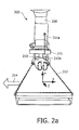
- Figure 2a shows a patient under examination 210 positioned within a C-arm system 200.
- the patient 210 is supported by a movable table 212, which table can be shifted along the x-axis, along the y-axis and along the z-axis.
- the C-arm system 200 comprises a robotic arm 208, at which a not visible C-arm is attached in a rotatable manner.
- a not visible X-ray source and an X-ray detector 215 are attached to the C-arm.
- the C-arm is capable of rotating around a z-axis such that the X-ray source and the X-ray detector 215 rotate around the patient 210 within a plane being oriented parallel to the x-axis as well as to the y-axis.
- Figure 2b shows the patient 210 within the C-arm system 200, whereby the patient's heart 210a is positioned in the iso-center.
- the iso-centering is indicated by the arrow 211b, which is aligned with the optical axis of the X-ray detector 215. In that case, the patient's body as a whole is shifted to the left compared to the iso-center of the C-arm.
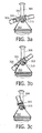
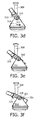
- Figures 3a-3k illustrate the combination of a rotational movement of a C-arm 301, which rotational movement is coupled in a synchronized manner with a horizontal movement of a patient table 312 in order to avoid a collision between an X-ray detector 315 of the C-arm 301 with a shoulder of the patient 310.
- the C-arm 301 is attached in a rotatable manner to a ceiling of an examination laboratory by means of a robotic arm 308.
- the table 312 is shifted to the right such that the heart of the patient is offset from the iso-center.
- This table movement is indicated in Figure 3d by the arrow 314d.
- the right shoulder of the patient 310 is also moved to the right such that a collision between the X-ray detector 315 and the shoulder can be avoided.
- the accessible angular range of the C-arm 301 is increased such that further X-ray attenuation data may be acquired at more extreme projection angles.
- the X-ray detector 315 of the C-arm 301 can be rotated around the shoulder of the patient 310 without having the risk of a collision.
- the intermediate table movement synchronized has the advantage, that the total accessible angular range can be increased in particular when thick patients are examined.
- the full angular range of a C-arm system can be exploited.
- the C-arm system FD20 Allura developed by Philips is capable of a C-arm propeller rotation from 120° left anterior oblique (LAO) to 185° right anterior oblique (RAO).
- LAO left anterior oblique
- REO right anterior oblique
- the C-arm system FD20 Allura cannot be used for cardiac applications because this full angular range cannot be used in particular for larger respectively thicker patients. Therefore, depending on the patient size, the C-arm movement would be limited to approximately 60° RAO only.
- the acquisition protocols for 3D coronary reconstruction require a C-arm propeller movement from 120° LAO to 60° RAO propeller movement.
- FIG. 4 shows a data processing device 425, which is adapted to perform an above-described method for acquiring a series of X-ray attenuation data of an object under examination by means of a rotatable X-ray scanning unit.
- the data processing device 425 comprises a central processing unit (CPU) or image processor 461.
- the image processor 461 is connected to a memory 462 for temporally storing acquired X-ray attenuation data. Via a bus system 465 the image processor 461 is connected to a plurality of input/output network or diagnosis devices of the C-arm system described above.
- the image processor 461 is connected to a display device 463, for example a computer monitor, for displaying information or one or more images reconstructed by the image processor 461.
- An operator or user may interact with the image processor 461 via a keyboard 464 and/or any other output devices, which are not depicted in Figure 4 .
Landscapes
- Health & Medical Sciences (AREA)
- Life Sciences & Earth Sciences (AREA)
- Medical Informatics (AREA)
- Engineering & Computer Science (AREA)
- Radiology & Medical Imaging (AREA)
- Molecular Biology (AREA)
- Biophysics (AREA)
- Nuclear Medicine, Radiotherapy & Molecular Imaging (AREA)
- Optics & Photonics (AREA)
- Pathology (AREA)
- Physics & Mathematics (AREA)
- Biomedical Technology (AREA)
- Heart & Thoracic Surgery (AREA)
- High Energy & Nuclear Physics (AREA)
- Surgery (AREA)
- Animal Behavior & Ethology (AREA)
- General Health & Medical Sciences (AREA)
- Public Health (AREA)
- Veterinary Medicine (AREA)
- Vascular Medicine (AREA)
- Dentistry (AREA)
- Oral & Maxillofacial Surgery (AREA)
- Apparatus For Radiation Diagnosis (AREA)
Claims (15)
- Verfahren zum Erfassen einer Serie von zweidimensionalen Röntgenabschwächungsdaten eines untersuchten Objekts (110, 310) mittels eines Röntgenbildgebungsgeräts (100) mit einer Röntgenabtasteinheit (101, 301), wobei das Verfahren die folgenden Schritte umfasst:- Erfassen einer Serie von zweidimensionalen Röntgenabschwächungsdaten eines untersuchten Objekts,
wobei die Röntgenabtasteinheit (101, 301) derartig um eine Rotationsachse gedreht wird, dass das untersuchte Objekt (110, 310) unter verschiedenen Projektionswinkeln abgetastet wird,
wobei das untersuchte Objekt (110, 310) in eine Richtung quer zur Rotationsachse bewegt wird, wobei die Bewegung des untersuchten Objekts (110, 310) mit der Rotation der Röntgenabtasteinheit (101, 301) gekoppelt ist, und- Rekonstruieren einer dreidimensionalen Darstellung des untersuchten Objekts (110, 310) basierend auf der erfassten Serie von zweidimensionalen Röntgenabschwächungsdaten durch Kombinieren der Projektionsdaten, die sowohl unter verschiedenen Winkelpositionen der Abtasteinheit (101, 301) als auch bei verschiedenen translatorische Positionen des Objekts (110, 310) erfasst wurden. - Verfahren nach Anspruch 1, das weiterhin die folgenden Schritte umfasst:Drehen der Röntgenabtasteinheit (101, 301) in eine erste vordefinierte Winkelposition, wobei sich das zu untersuchende Objekt (110, 310) an einer ersten translatorischen Position befindet,Bewegen des untersuchten Objekts (110, 310) von der ersten translatorischen Position zu einer zweiten translatorischen Position, undDrehen der Röntgenabtasteinheit (101, 301) in eine zweite vordefinierte Winkelposition.
- Verfahren nach Anspruch 2, das weiterhin die folgenden Schritte umfasst:Bewegen des untersuchten Objekts (110, 310) von der zweiten translatorischen Position zurück zu der ersten translatorischen Position, undWeiterdrehen der Röntgenabtasteinheit (101, 301).
- Verfahren nach Anspruch 2, wobei
die Bewegung des untersuchten Objekts (110, 310) während einer Zeitspanne ausgeführt wird, in der die Rotation der Röntgenabtasteinheit (101, 301) vorübergehend gestoppt ist. - Verfahren nach Anspruch 2, wobei
die Bewegung des untersuchten Objekts (110, 310) während einer Zeitspanne ausgeführt wird, in der die Röntgenabtasteinheit (101, 301) von der ersten vordefinierten Winkelposition in die zweite vordefinierte Winkelposition gedreht wird. - Verfahren nach Anspruch 1, wobei
sich das untersuchte Objekt (110, 310) auf einem Auflageelement (112, 312) befindet, wobei dieses Auflageelement (112, 312) mit einem Antriebsmittel (113) zum Erzeugen der Bewegung des untersuchten Objekts (110, 310) gekoppelt ist. - Verfahren nach Anspruch 1, wobei
das untersuchte Objekt (110, 310) mindestens eine interessierende Region (110a, 210a) des Körpers eines Patienten ist. - Verfahren nach Anspruch 7, wobei
die interessierende Region ein Organ (110a, 210a) des Patienten (110, 310) ist, wobei sich das Organ (110a, 210a) außermittig innerhalb des Körpers des Patienten (110, 310) befindet, insbesondere ist die interessierende Region das Herz (110a, 210a) des Patienten (110, 310). - Verfahren nach Anspruch 7, das weiterhin den Schritt des Einführens eines Kontrastmittels in den Körper eines Patienten (110, 310) umfasst.
- Verfahren nach Anspruch 1, das weiterhin den Schritt des Durchführens einer Kalibrierprozedur für die Registrierung der Bewegung des untersuchten Objekts (110, 310) mit der Rotation der Röntgenabtasteinheit (101, 301) umfasst.
- Medizinisches Röntgenbildgebungsgerät, insbesondere ein C-Bogen-System (100), zum Erfassen einer Serie von zweidimensionalen Röntgenabschwächungsdaten eines untersuchten Objekts (110, 310), wobei das medizinische Röntgenbildgebungsgerät (100) Folgendes umfasst:eine Röntgenabtasteinheit (101, 301), die um eine Rotationsachse drehbar ist, wobei die Röntgenabtasteinheit (101, 301) Folgendes umfasst:eine Röntgenquelle (105), die vorgesehen ist, um ein Strahlenbündel (107) zu emittieren, undeinen Röntgendetektor (115), der vorgesehen ist, um das Strahlenbündel (107) zu detektieren, nachdem das Strahlenbündel (107) das untersuchte Objekt (110, 310) durchquert hat,eine Datenverarbeitungsvorrichtung (425) miteinem Datenprozessor (461), der vorgesehen ist, um das Verfahren nach Anspruch 1 zu steuern, undeinem Speicher (462) zum Speichern der Serie von erfassten zweidimensionalen Röntgenabschwächungsdaten.
- Medizinisches Röntgenbildgebungsgerät nach Anspruch 11, das weiterhin Folgendes umfasst:ein Auflageelement (112, 312) zum Tragen des untersuchten Objekts (110, 310), undein Antriebsmittel (113), das mit dem Auflageelement gekoppelt ist und vorgesehen ist, um die transversale Bewegung des untersuchten Objekts (110, 310) zu erzeugen.
- Medizinisches Röntgenbildgebungsgerät nach Anspruch 12, das weiterhin Folgendes umfasst:eine Steuereinheit (121), die mit dem Antriebsmittel (113) gekoppelt ist und vorgesehen ist, um die Bewegung des Auflageelements (112, 312) zu steuern.
- Computerlesbares Medium, auf dem ein Computerprogramm zum Erfassen einer Serie von zweidimensionalen Röntgenabschwächungsdaten eines untersuchten Objekts (110, 310) mittels eines Röntgenbildgebungsgeräts (100) mit einer drehbaren Röntgenabtasteinheit (101, 301) gespeichert ist,
wobei das Computerprogramm, wenn es durch den Datenprozessor (461) des Geräts nach Anspruch 11 ausgeführt wird, vorgesehen ist, um das Verfahren nach Anspruch 1 zu steuern. - Programmelement zum Erfassen einer Serie von zweidimensionalen Röntgenabschwächungsdaten eines untersuchten Objekts (110, 310) mittels eines Röntgenbildgebungsgeräts (100) mit einer drehbaren Röntgenabtasteinheit (101, 301),
wobei das Programmelement, wenn es durch den Datenprozessor (461) des Geräts nach Anspruch 11 ausgeführt wird, vorgesehen ist, um das Verfahren nach Anspruch 1 zu steuern.
Priority Applications (1)
| Application Number | Priority Date | Filing Date | Title |
|---|---|---|---|
| EP07826406A EP2068713B1 (de) | 2006-09-25 | 2007-09-17 | Verschiebung eines objekts für komplette trajektorien in einem rotierenden röntgenbildgebungssystem |
Applications Claiming Priority (3)
| Application Number | Priority Date | Filing Date | Title |
|---|---|---|---|
| EP06121190 | 2006-09-25 | ||
| EP07826406A EP2068713B1 (de) | 2006-09-25 | 2007-09-17 | Verschiebung eines objekts für komplette trajektorien in einem rotierenden röntgenbildgebungssystem |
| PCT/IB2007/053744 WO2008038176A1 (en) | 2006-09-25 | 2007-09-17 | Shifting an object for complete trajectories in rotational x-ray imaging |
Publications (2)
| Publication Number | Publication Date |
|---|---|
| EP2068713A1 EP2068713A1 (de) | 2009-06-17 |
| EP2068713B1 true EP2068713B1 (de) | 2012-07-18 |
Family
ID=39059385
Family Applications (1)
| Application Number | Title | Priority Date | Filing Date |
|---|---|---|---|
| EP07826406A Not-in-force EP2068713B1 (de) | 2006-09-25 | 2007-09-17 | Verschiebung eines objekts für komplette trajektorien in einem rotierenden röntgenbildgebungssystem |
Country Status (5)
| Country | Link |
|---|---|
| US (1) | US8045677B2 (de) |
| EP (1) | EP2068713B1 (de) |
| JP (1) | JP5597394B2 (de) |
| CN (1) | CN101516267B (de) |
| WO (1) | WO2008038176A1 (de) |
Cited By (2)
| Publication number | Priority date | Publication date | Assignee | Title |
|---|---|---|---|---|
| DE202017002625U1 (de) | 2017-05-16 | 2017-05-29 | Ziehm Imaging Gmbh | Röntgensystem mit einem Kegelstrahl-C-Bogen-Röntgengerät zum Erzeugen eines in der Zentralschicht vollständigen 3D-Datensatzes zur Volumenrekonstruktion |
| DE102017004705A1 (de) | 2017-05-16 | 2018-11-22 | Ziehm Imaging Gmbh | Verfahren zum Erzeugen eines in der Zentralschicht vollständigen 3D-Datensatzes zur Volumenrekonstruktion und Röntgensystem mit einem Kegelstrahl-C-Bogen-Röntgengerät zur Durchführung des Verfahrens |
Families Citing this family (21)
| Publication number | Priority date | Publication date | Assignee | Title |
|---|---|---|---|---|
| EP2408375B1 (de) | 2009-03-20 | 2017-12-06 | Orthoscan Incorporated | Bewegliche bildgebungsvorrichtung |
| US10751551B2 (en) * | 2010-04-16 | 2020-08-25 | James P. Bennett | Integrated imaging-cancer treatment apparatus and method of use thereof |
| KR101114541B1 (ko) | 2010-08-25 | 2012-02-27 | (주)제노레이 | X선 진단장비의 구동 방법 |
| WO2012082799A1 (en) | 2010-12-13 | 2012-06-21 | Orthoscan, Inc. | Mobile fluoroscopic imaging system |
| JP5731888B2 (ja) * | 2011-04-22 | 2015-06-10 | 株式会社東芝 | X線画像診断装置 |
| US9510771B1 (en) | 2011-10-28 | 2016-12-06 | Nuvasive, Inc. | Systems and methods for performing spine surgery |
| WO2013073723A1 (ko) * | 2011-11-16 | 2013-05-23 | (주)제노레이 | X선 진단장비의 구동 방법 |
| BR112014032112A2 (pt) | 2012-06-28 | 2017-06-27 | Koninklijke Philips Nv | sistema de aquisição de imagem; e método para aquisição de imagem multimodal |
| JP6125200B2 (ja) * | 2012-11-05 | 2017-05-10 | 株式会社吉田製作所 | X線撮影装置 |
| WO2014192960A1 (ja) * | 2013-05-31 | 2014-12-04 | 株式会社 東芝 | X線診断装置 |
| US9848922B2 (en) | 2013-10-09 | 2017-12-26 | Nuvasive, Inc. | Systems and methods for performing spine surgery |
| JP7001371B2 (ja) | 2016-06-13 | 2022-01-19 | シャンハイ ユナイティッド イメージング ヘルスケア カンパニー リミティッド | X線スキャナの位置決めシステム及び方法 |
| CN106344053B (zh) * | 2016-09-09 | 2021-01-22 | 上海联影医疗科技股份有限公司 | X射线成像设备的成像方法及定位装置 |
| EP3360482A1 (de) * | 2017-02-09 | 2018-08-15 | Koninklijke Philips N.V. | Isozentrierung in c-arm-computertomographie |
| CN107315923A (zh) * | 2017-08-14 | 2017-11-03 | 上海联影医疗科技有限公司 | 一种调整医疗设备的系统和方法 |
| US10779791B2 (en) * | 2018-03-16 | 2020-09-22 | General Electric Company | System and method for mobile X-ray imaging |
| EP3679862A1 (de) * | 2019-01-09 | 2020-07-15 | Koninklijke Philips N.V. | Adaptive spiralförmige computertomographie |
| EP3797695B1 (de) * | 2019-09-30 | 2022-06-08 | Siemens Healthcare GmbH | Automatische positionierung einer röntgenquelle mittels segmentierung |
| WO2022032455A1 (en) * | 2020-08-10 | 2022-02-17 | Shanghai United Imaging Healthcare Co., Ltd. | Imaging systems and methods |
| CN112782200A (zh) * | 2021-03-10 | 2021-05-11 | 深圳市卓茂科技有限公司 | 一种基于x-ray的全自动3D检测设备 |
| CN114295650A (zh) * | 2021-08-24 | 2022-04-08 | 上海超群检测科技股份有限公司 | X射线ct检测装置及检测方法 |
Family Cites Families (32)
| Publication number | Priority date | Publication date | Assignee | Title |
|---|---|---|---|---|
| JPS6275337A (ja) * | 1985-09-30 | 1987-04-07 | Toshiba Corp | リング状物体検査用ctスキヤナ |
| US4789929A (en) | 1987-05-14 | 1988-12-06 | Hitachi Medical Corporation | CT system for spirally scanning subject on a movable bed synchronized to X-ray tube revolution |
| FR2641180B1 (fr) * | 1988-12-30 | 1997-08-22 | Gen Electric Cgr | Systeme de radiologie pour examen angiographique et procede de mise en oeuvre |
| JP2824602B2 (ja) * | 1990-10-05 | 1998-11-11 | 株式会社モリタ製作所 | デジタルパノラマx線撮影装置 |
| US5090037A (en) * | 1990-11-19 | 1992-02-18 | General Electric Company | Helical scanning computed tomography with tracking x-ray source |
| JP3767910B2 (ja) * | 1992-09-11 | 2006-04-19 | 株式会社東芝 | X線診断装置 |
| US5448607A (en) * | 1994-02-08 | 1995-09-05 | Analogic Corporation | X-ray tomography system with gantry pivot and translation control |
| JP3378401B2 (ja) * | 1994-08-30 | 2003-02-17 | 株式会社日立メディコ | X線装置 |
| JP3638353B2 (ja) * | 1995-10-27 | 2005-04-13 | 株式会社東芝 | X線診断装置 |
| JP3523729B2 (ja) | 1995-10-27 | 2004-04-26 | 株式会社東芝 | X線診断装置 |
| JPH1057367A (ja) * | 1996-08-27 | 1998-03-03 | Shimadzu Corp | X線ct装置 |
| BE1011045A3 (fr) | 1997-03-14 | 1999-04-06 | Ucb Sa | Compositions pharmaceutiques pour la liberation controlee de substances actives. |
| JPH11206744A (ja) * | 1998-01-30 | 1999-08-03 | Toshiba Corp | X線診断装置 |
| DE19909527C2 (de) * | 1999-03-04 | 2003-08-14 | Siemens Ag | CT-Gerät zur Abbildung von zur Systemachse geneigten Schichten |
| US6246742B1 (en) * | 1999-06-22 | 2001-06-12 | General Electric Company | Local CT image reconstruction with limited x-ray exposure |
| JP4528426B2 (ja) * | 2000-10-30 | 2010-08-18 | 株式会社東芝 | X線診断装置 |
| US6764217B2 (en) | 2000-10-30 | 2004-07-20 | Kabushiki Kaisha Toshiba | X-ray diagnosis apparatus |
| JP4836323B2 (ja) * | 2000-12-22 | 2011-12-14 | 株式会社東芝 | X線画像撮影装置 |
| US7065395B2 (en) | 2001-03-19 | 2006-06-20 | Ge Medical Systems Global Technology Company, Llc | Method and apparatus for cardiac radiological examination in coronary angiography |
| JP4329355B2 (ja) * | 2003-02-21 | 2009-09-09 | 株式会社島津製作所 | X線撮影装置 |
| JP3748433B2 (ja) | 2003-03-05 | 2006-02-22 | 株式会社日立製作所 | ベッド位置決め装置及びその位置決め方法 |
| US7154991B2 (en) | 2003-10-17 | 2006-12-26 | Accuray, Inc. | Patient positioning assembly for therapeutic radiation system |
| US7542544B2 (en) | 2004-01-06 | 2009-06-02 | The Regents Of The University Of Michigan | Ultrasound gating of cardiac CT scans |
| DE102004015858A1 (de) | 2004-03-31 | 2005-10-27 | Siemens Ag | Bildgebende medizinische Untersuchungsvorrichtung |
| US7860550B2 (en) | 2004-04-06 | 2010-12-28 | Accuray, Inc. | Patient positioning assembly |
| US7166852B2 (en) | 2004-04-06 | 2007-01-23 | Accuray, Inc. | Treatment target positioning system |
| JP4504743B2 (ja) * | 2004-06-17 | 2010-07-14 | 東芝Itコントロールシステム株式会社 | コンピュータ断層撮影装置 |
| JP3971428B2 (ja) * | 2005-03-03 | 2007-09-05 | 株式会社東芝 | X線診断装置 |
| US7313215B2 (en) * | 2005-06-06 | 2007-12-25 | General Electric Company | Step-and-shoot cardiac CT imaging |
| US7486759B2 (en) * | 2006-10-12 | 2009-02-03 | J. Morita Manufacturing Corporation | X-ray computer tomography apparatus |
| JP5539729B2 (ja) * | 2007-11-16 | 2014-07-02 | 株式会社モリタ製作所 | X線ct撮影装置 |
| US8633445B2 (en) * | 2008-05-19 | 2014-01-21 | Varian Medical Systems, Inc. | Multi-energy X-ray imaging |
-
2007
- 2007-09-17 JP JP2009528829A patent/JP5597394B2/ja not_active Expired - Fee Related
- 2007-09-17 WO PCT/IB2007/053744 patent/WO2008038176A1/en active Application Filing
- 2007-09-17 CN CN200780035426.9A patent/CN101516267B/zh not_active Expired - Fee Related
- 2007-09-17 EP EP07826406A patent/EP2068713B1/de not_active Not-in-force
- 2007-09-17 US US12/441,613 patent/US8045677B2/en not_active Expired - Fee Related
Cited By (2)
| Publication number | Priority date | Publication date | Assignee | Title |
|---|---|---|---|---|
| DE202017002625U1 (de) | 2017-05-16 | 2017-05-29 | Ziehm Imaging Gmbh | Röntgensystem mit einem Kegelstrahl-C-Bogen-Röntgengerät zum Erzeugen eines in der Zentralschicht vollständigen 3D-Datensatzes zur Volumenrekonstruktion |
| DE102017004705A1 (de) | 2017-05-16 | 2018-11-22 | Ziehm Imaging Gmbh | Verfahren zum Erzeugen eines in der Zentralschicht vollständigen 3D-Datensatzes zur Volumenrekonstruktion und Röntgensystem mit einem Kegelstrahl-C-Bogen-Röntgengerät zur Durchführung des Verfahrens |
Also Published As
| Publication number | Publication date |
|---|---|
| CN101516267B (zh) | 2014-03-05 |
| WO2008038176A1 (en) | 2008-04-03 |
| CN101516267A (zh) | 2009-08-26 |
| EP2068713A1 (de) | 2009-06-17 |
| JP5597394B2 (ja) | 2014-10-01 |
| US8045677B2 (en) | 2011-10-25 |
| JP2010504126A (ja) | 2010-02-12 |
| US20100027742A1 (en) | 2010-02-04 |
Similar Documents
| Publication | Publication Date | Title |
|---|---|---|
| EP2068713B1 (de) | Verschiebung eines objekts für komplette trajektorien in einem rotierenden röntgenbildgebungssystem | |
| US6814489B2 (en) | 3D reconstruction system and method utilizing a variable X-ray source to image distance | |
| JP6181459B2 (ja) | 放射線治療システム | |
| US7809102B2 (en) | Method and apparatus for positioning a subject in a CT scanner | |
| US7020235B2 (en) | Method for generating a volume dataset | |
| US7436927B2 (en) | Imaging apparatus and method for the operation thereof | |
| CN110366439B (zh) | 图像引导系统、上位机、放射治疗系统及介质 | |
| EP3362148A1 (de) | System und verfahren zur überwachung von strukturellen bewegungen während einer strahlungstherapie | |
| WO2010101208A1 (ja) | X線ct装置及び断層像撮影方法 | |
| KR20070104924A (ko) | 가변 재구성 기하적 구조를 포함하는 단층촬영기기 | |
| JP2004517670A (ja) | 透視イメージング・システムを用いてコンピュータ断層画像を取得しかつ表示するための方法及び装置 | |
| JP5642444B2 (ja) | 放射線治療装置の作動方法および放射線治療装置制御装置 | |
| US20070211847A1 (en) | Method for recording projection data sets of an object under examination | |
| EP1589876B2 (de) | Computertomographische untersuchung | |
| US20050084147A1 (en) | Method and apparatus for image reconstruction with projection images acquired in a non-circular arc | |
| JP3725277B2 (ja) | X線診断システムおよびx線ctスキャナ | |
| US20010054695A1 (en) | Method and device for multiple viewpoint acquisition of images | |
| KR102619994B1 (ko) | 의용 화상 처리 장치, 기억 매체, 의용 장치, 및 치료 시스템 | |
| US7050531B2 (en) | Method for intraoperative generation of an updated volume dataset | |
| JP7123919B2 (ja) | X線撮像システムの軌道を決定する方法及びシステム | |
| JPH11244280A (ja) | コンピュータ断層装置 | |
| JP2018099505A (ja) | X線診断装置、医用画像診断システム及び制御方法 | |
| US11622739B2 (en) | Intra-surgery imaging system | |
| US20230218250A1 (en) | Intra-surgery imaging system | |
| JP2019000302A (ja) | アンギオct装置 |
Legal Events
| Date | Code | Title | Description |
|---|---|---|---|
| PUAI | Public reference made under article 153(3) epc to a published international application that has entered the european phase |
Free format text: ORIGINAL CODE: 0009012 |
|
| 17P | Request for examination filed |
Effective date: 20090427 |
|
| AK | Designated contracting states |
Kind code of ref document: A1 Designated state(s): AT BE BG CH CY CZ DE DK EE ES FI FR GB GR HU IE IS IT LI LT LU LV MC MT NL PL PT RO SE SI SK TR |
|
| AX | Request for extension of the european patent |
Extension state: AL BA HR MK RS |
|
| RAP1 | Party data changed (applicant data changed or rights of an application transferred) |
Owner name: THE REGENTS OF THE UNIVERSITY OF COLORADO Owner name: KONINKLIJKE PHILIPS ELECTRONICS N.V. |
|
| 17Q | First examination report despatched |
Effective date: 20090814 |
|
| GRAP | Despatch of communication of intention to grant a patent |
Free format text: ORIGINAL CODE: EPIDOSNIGR1 |
|
| DAX | Request for extension of the european patent (deleted) | ||
| GRAS | Grant fee paid |
Free format text: ORIGINAL CODE: EPIDOSNIGR3 |
|
| GRAA | (expected) grant |
Free format text: ORIGINAL CODE: 0009210 |
|
| AK | Designated contracting states |
Kind code of ref document: B1 Designated state(s): AT BE BG CH CY CZ DE DK EE ES FI FR GB GR HU IE IS IT LI LT LU LV MC MT NL PL PT RO SE SI SK TR |
|
| REG | Reference to a national code |
Ref country code: GB Ref legal event code: FG4D |
|
| REG | Reference to a national code |
Ref country code: CH Ref legal event code: EP |
|
| REG | Reference to a national code |
Ref country code: AT Ref legal event code: REF Ref document number: 566730 Country of ref document: AT Kind code of ref document: T Effective date: 20120815 Ref country code: IE Ref legal event code: FG4D |
|
| REG | Reference to a national code |
Ref country code: GB Ref legal event code: 746 Effective date: 20120802 |
|
| REG | Reference to a national code |
Ref country code: DE Ref legal event code: R096 Ref document number: 602007024092 Country of ref document: DE Effective date: 20120913 |
|
| REG | Reference to a national code |
Ref country code: NL Ref legal event code: VDEP Effective date: 20120718 |
|
| REG | Reference to a national code |
Ref country code: AT Ref legal event code: MK05 Ref document number: 566730 Country of ref document: AT Kind code of ref document: T Effective date: 20120718 |
|
| REG | Reference to a national code |
Ref country code: LT Ref legal event code: MG4D Effective date: 20120718 |
|
| PG25 | Lapsed in a contracting state [announced via postgrant information from national office to epo] |
Ref country code: FI Free format text: LAPSE BECAUSE OF FAILURE TO SUBMIT A TRANSLATION OF THE DESCRIPTION OR TO PAY THE FEE WITHIN THE PRESCRIBED TIME-LIMIT Effective date: 20120718 Ref country code: LT Free format text: LAPSE BECAUSE OF FAILURE TO SUBMIT A TRANSLATION OF THE DESCRIPTION OR TO PAY THE FEE WITHIN THE PRESCRIBED TIME-LIMIT Effective date: 20120718 Ref country code: BE Free format text: LAPSE BECAUSE OF FAILURE TO SUBMIT A TRANSLATION OF THE DESCRIPTION OR TO PAY THE FEE WITHIN THE PRESCRIBED TIME-LIMIT Effective date: 20120718 Ref country code: AT Free format text: LAPSE BECAUSE OF FAILURE TO SUBMIT A TRANSLATION OF THE DESCRIPTION OR TO PAY THE FEE WITHIN THE PRESCRIBED TIME-LIMIT Effective date: 20120718 Ref country code: CY Free format text: LAPSE BECAUSE OF FAILURE TO SUBMIT A TRANSLATION OF THE DESCRIPTION OR TO PAY THE FEE WITHIN THE PRESCRIBED TIME-LIMIT Effective date: 20120718 Ref country code: IS Free format text: LAPSE BECAUSE OF FAILURE TO SUBMIT A TRANSLATION OF THE DESCRIPTION OR TO PAY THE FEE WITHIN THE PRESCRIBED TIME-LIMIT Effective date: 20121118 |
|
| PG25 | Lapsed in a contracting state [announced via postgrant information from national office to epo] |
Ref country code: GR Free format text: LAPSE BECAUSE OF FAILURE TO SUBMIT A TRANSLATION OF THE DESCRIPTION OR TO PAY THE FEE WITHIN THE PRESCRIBED TIME-LIMIT Effective date: 20121019 Ref country code: SE Free format text: LAPSE BECAUSE OF FAILURE TO SUBMIT A TRANSLATION OF THE DESCRIPTION OR TO PAY THE FEE WITHIN THE PRESCRIBED TIME-LIMIT Effective date: 20120718 Ref country code: SI Free format text: LAPSE BECAUSE OF FAILURE TO SUBMIT A TRANSLATION OF THE DESCRIPTION OR TO PAY THE FEE WITHIN THE PRESCRIBED TIME-LIMIT Effective date: 20120718 Ref country code: LV Free format text: LAPSE BECAUSE OF FAILURE TO SUBMIT A TRANSLATION OF THE DESCRIPTION OR TO PAY THE FEE WITHIN THE PRESCRIBED TIME-LIMIT Effective date: 20120718 Ref country code: PT Free format text: LAPSE BECAUSE OF FAILURE TO SUBMIT A TRANSLATION OF THE DESCRIPTION OR TO PAY THE FEE WITHIN THE PRESCRIBED TIME-LIMIT Effective date: 20121119 Ref country code: PL Free format text: LAPSE BECAUSE OF FAILURE TO SUBMIT A TRANSLATION OF THE DESCRIPTION OR TO PAY THE FEE WITHIN THE PRESCRIBED TIME-LIMIT Effective date: 20120718 |
|
| PG25 | Lapsed in a contracting state [announced via postgrant information from national office to epo] |
Ref country code: NL Free format text: LAPSE BECAUSE OF FAILURE TO SUBMIT A TRANSLATION OF THE DESCRIPTION OR TO PAY THE FEE WITHIN THE PRESCRIBED TIME-LIMIT Effective date: 20120718 |
|
| PG25 | Lapsed in a contracting state [announced via postgrant information from national office to epo] |
Ref country code: DK Free format text: LAPSE BECAUSE OF FAILURE TO SUBMIT A TRANSLATION OF THE DESCRIPTION OR TO PAY THE FEE WITHIN THE PRESCRIBED TIME-LIMIT Effective date: 20120718 Ref country code: RO Free format text: LAPSE BECAUSE OF FAILURE TO SUBMIT A TRANSLATION OF THE DESCRIPTION OR TO PAY THE FEE WITHIN THE PRESCRIBED TIME-LIMIT Effective date: 20120718 Ref country code: EE Free format text: LAPSE BECAUSE OF FAILURE TO SUBMIT A TRANSLATION OF THE DESCRIPTION OR TO PAY THE FEE WITHIN THE PRESCRIBED TIME-LIMIT Effective date: 20120718 Ref country code: ES Free format text: LAPSE BECAUSE OF FAILURE TO SUBMIT A TRANSLATION OF THE DESCRIPTION OR TO PAY THE FEE WITHIN THE PRESCRIBED TIME-LIMIT Effective date: 20121029 Ref country code: MC Free format text: LAPSE BECAUSE OF NON-PAYMENT OF DUE FEES Effective date: 20120930 Ref country code: CZ Free format text: LAPSE BECAUSE OF FAILURE TO SUBMIT A TRANSLATION OF THE DESCRIPTION OR TO PAY THE FEE WITHIN THE PRESCRIBED TIME-LIMIT Effective date: 20120718 |
|
| REG | Reference to a national code |
Ref country code: CH Ref legal event code: PL |
|
| PLBE | No opposition filed within time limit |
Free format text: ORIGINAL CODE: 0009261 |
|
| STAA | Information on the status of an ep patent application or granted ep patent |
Free format text: STATUS: NO OPPOSITION FILED WITHIN TIME LIMIT |
|
| PG25 | Lapsed in a contracting state [announced via postgrant information from national office to epo] |
Ref country code: IT Free format text: LAPSE BECAUSE OF FAILURE TO SUBMIT A TRANSLATION OF THE DESCRIPTION OR TO PAY THE FEE WITHIN THE PRESCRIBED TIME-LIMIT Effective date: 20120718 Ref country code: SK Free format text: LAPSE BECAUSE OF FAILURE TO SUBMIT A TRANSLATION OF THE DESCRIPTION OR TO PAY THE FEE WITHIN THE PRESCRIBED TIME-LIMIT Effective date: 20120718 |
|
| REG | Reference to a national code |
Ref country code: IE Ref legal event code: MM4A |
|
| 26N | No opposition filed |
Effective date: 20130419 |
|
| PG25 | Lapsed in a contracting state [announced via postgrant information from national office to epo] |
Ref country code: CH Free format text: LAPSE BECAUSE OF NON-PAYMENT OF DUE FEES Effective date: 20120930 Ref country code: LI Free format text: LAPSE BECAUSE OF NON-PAYMENT OF DUE FEES Effective date: 20120930 Ref country code: BG Free format text: LAPSE BECAUSE OF FAILURE TO SUBMIT A TRANSLATION OF THE DESCRIPTION OR TO PAY THE FEE WITHIN THE PRESCRIBED TIME-LIMIT Effective date: 20121018 Ref country code: IE Free format text: LAPSE BECAUSE OF NON-PAYMENT OF DUE FEES Effective date: 20120917 |
|
| REG | Reference to a national code |
Ref country code: DE Ref legal event code: R097 Ref document number: 602007024092 Country of ref document: DE Effective date: 20130419 |
|
| PG25 | Lapsed in a contracting state [announced via postgrant information from national office to epo] |
Ref country code: MT Free format text: LAPSE BECAUSE OF FAILURE TO SUBMIT A TRANSLATION OF THE DESCRIPTION OR TO PAY THE FEE WITHIN THE PRESCRIBED TIME-LIMIT Effective date: 20120718 |
|
| REG | Reference to a national code |
Ref country code: DE Ref legal event code: R081 Ref document number: 602007024092 Country of ref document: DE Owner name: KONINKLIJKE PHILIPS N.V., NL Free format text: FORMER OWNER: KONINKLIJKE PHILIPS ELECTRONICS, THE REGENTS OF THE UNIVERSITY O, , US Effective date: 20140401 Ref country code: DE Ref legal event code: R081 Ref document number: 602007024092 Country of ref document: DE Owner name: THE REGENTS OF THE UNIVERSITY OF COLORADO, US Free format text: FORMER OWNER: KONINKLIJKE PHILIPS ELECTRONICS, THE REGENTS OF THE UNIVERSITY O, , US Effective date: 20140401 Ref country code: DE Ref legal event code: R081 Ref document number: 602007024092 Country of ref document: DE Owner name: THE REGENTS OF THE UNIVERSITY OF COLORADO, DEN, US Free format text: FORMER OWNER: KONINKLIJKE PHILIPS ELECTRONICS, THE REGENTS OF THE UNIVERSITY O, , US Effective date: 20140401 Ref country code: DE Ref legal event code: R081 Ref document number: 602007024092 Country of ref document: DE Owner name: KONINKLIJKE PHILIPS N.V., NL Free format text: FORMER OWNERS: KONINKLIJKE PHILIPS ELECTRONICS N.V., EINDHOVEN, NL; THE REGENTS OF THE UNIVERSITY OF COLORADO, DENVER, COL., US Effective date: 20140401 Ref country code: DE Ref legal event code: R081 Ref document number: 602007024092 Country of ref document: DE Owner name: THE REGENTS OF THE UNIVERSITY OF COLORADO, DEN, US Free format text: FORMER OWNERS: KONINKLIJKE PHILIPS ELECTRONICS N.V., EINDHOVEN, NL; THE REGENTS OF THE UNIVERSITY OF COLORADO, DENVER, COL., US Effective date: 20140401 |
|
| PG25 | Lapsed in a contracting state [announced via postgrant information from national office to epo] |
Ref country code: LU Free format text: LAPSE BECAUSE OF NON-PAYMENT OF DUE FEES Effective date: 20120917 |
|
| PG25 | Lapsed in a contracting state [announced via postgrant information from national office to epo] |
Ref country code: HU Free format text: LAPSE BECAUSE OF FAILURE TO SUBMIT A TRANSLATION OF THE DESCRIPTION OR TO PAY THE FEE WITHIN THE PRESCRIBED TIME-LIMIT Effective date: 20070917 |
|
| REG | Reference to a national code |
Ref country code: FR Ref legal event code: CA Effective date: 20140806 Ref country code: FR Ref legal event code: CD Owner name: THE REGENTS OF THE UNIVERSITY OF COLORADO, US Effective date: 20140806 Ref country code: FR Ref legal event code: CD Owner name: KONINKLIJKE PHILIPS ELECTRONICS N Effective date: 20140806 |
|
| PGFP | Annual fee paid to national office [announced via postgrant information from national office to epo] |
Ref country code: TR Payment date: 20140910 Year of fee payment: 8 |
|
| REG | Reference to a national code |
Ref country code: FR Ref legal event code: PLFP Year of fee payment: 9 |
|
| REG | Reference to a national code |
Ref country code: FR Ref legal event code: PLFP Year of fee payment: 10 |
|
| REG | Reference to a national code |
Ref country code: FR Ref legal event code: PLFP Year of fee payment: 11 |
|
| REG | Reference to a national code |
Ref country code: DE Ref legal event code: R084 Ref document number: 602007024092 Country of ref document: DE |
|
| REG | Reference to a national code |
Ref country code: FR Ref legal event code: PLFP Year of fee payment: 12 |
|
| PGFP | Annual fee paid to national office [announced via postgrant information from national office to epo] |
Ref country code: FR Payment date: 20180927 Year of fee payment: 12 |
|
| PGFP | Annual fee paid to national office [announced via postgrant information from national office to epo] |
Ref country code: GB Payment date: 20180928 Year of fee payment: 12 |
|
| PGFP | Annual fee paid to national office [announced via postgrant information from national office to epo] |
Ref country code: DE Payment date: 20181130 Year of fee payment: 12 |
|
| REG | Reference to a national code |
Ref country code: DE Ref legal event code: R119 Ref document number: 602007024092 Country of ref document: DE |
|
| PG25 | Lapsed in a contracting state [announced via postgrant information from national office to epo] |
Ref country code: DE Free format text: LAPSE BECAUSE OF NON-PAYMENT OF DUE FEES Effective date: 20200401 |
|
| GBPC | Gb: european patent ceased through non-payment of renewal fee |
Effective date: 20190917 |
|
| PG25 | Lapsed in a contracting state [announced via postgrant information from national office to epo] |
Ref country code: GB Free format text: LAPSE BECAUSE OF NON-PAYMENT OF DUE FEES Effective date: 20190917 Ref country code: FR Free format text: LAPSE BECAUSE OF NON-PAYMENT OF DUE FEES Effective date: 20190930 |
|
| PG25 | Lapsed in a contracting state [announced via postgrant information from national office to epo] |
Ref country code: TR Free format text: LAPSE BECAUSE OF NON-PAYMENT OF DUE FEES Effective date: 20160917 |