EP2068161A2 - Moniteur de performance de la batterie - Google Patents
Moniteur de performance de la batterie Download PDFInfo
- Publication number
- EP2068161A2 EP2068161A2 EP08013201A EP08013201A EP2068161A2 EP 2068161 A2 EP2068161 A2 EP 2068161A2 EP 08013201 A EP08013201 A EP 08013201A EP 08013201 A EP08013201 A EP 08013201A EP 2068161 A2 EP2068161 A2 EP 2068161A2
- Authority
- EP
- European Patent Office
- Prior art keywords
- battery
- conductance
- soc
- value
- charged
- Prior art date
- Legal status (The legal status is an assumption and is not a legal conclusion. Google has not performed a legal analysis and makes no representation as to the accuracy of the status listed.)
- Granted
Links
Images


Classifications
-
- G—PHYSICS
- G01—MEASURING; TESTING
- G01R—MEASURING ELECTRIC VARIABLES; MEASURING MAGNETIC VARIABLES
- G01R31/00—Arrangements for testing electric properties; Arrangements for locating electric faults; Arrangements for electrical testing characterised by what is being tested not provided for elsewhere
- G01R31/36—Arrangements for testing, measuring or monitoring the electrical condition of accumulators or electric batteries, e.g. capacity or state of charge [SoC]
- G01R31/389—Measuring internal impedance, internal conductance or related variables
-
- B—PERFORMING OPERATIONS; TRANSPORTING
- B60—VEHICLES IN GENERAL
- B60L—PROPULSION OF ELECTRICALLY-PROPELLED VEHICLES; SUPPLYING ELECTRIC POWER FOR AUXILIARY EQUIPMENT OF ELECTRICALLY-PROPELLED VEHICLES; ELECTRODYNAMIC BRAKE SYSTEMS FOR VEHICLES IN GENERAL; MAGNETIC SUSPENSION OR LEVITATION FOR VEHICLES; MONITORING OPERATING VARIABLES OF ELECTRICALLY-PROPELLED VEHICLES; ELECTRIC SAFETY DEVICES FOR ELECTRICALLY-PROPELLED VEHICLES
- B60L58/00—Methods or circuit arrangements for monitoring or controlling batteries or fuel cells, specially adapted for electric vehicles
- B60L58/10—Methods or circuit arrangements for monitoring or controlling batteries or fuel cells, specially adapted for electric vehicles for monitoring or controlling batteries
- B60L58/12—Methods or circuit arrangements for monitoring or controlling batteries or fuel cells, specially adapted for electric vehicles for monitoring or controlling batteries responding to state of charge [SoC]
- B60L58/15—Preventing overcharging
-
- B—PERFORMING OPERATIONS; TRANSPORTING
- B60—VEHICLES IN GENERAL
- B60L—PROPULSION OF ELECTRICALLY-PROPELLED VEHICLES; SUPPLYING ELECTRIC POWER FOR AUXILIARY EQUIPMENT OF ELECTRICALLY-PROPELLED VEHICLES; ELECTRODYNAMIC BRAKE SYSTEMS FOR VEHICLES IN GENERAL; MAGNETIC SUSPENSION OR LEVITATION FOR VEHICLES; MONITORING OPERATING VARIABLES OF ELECTRICALLY-PROPELLED VEHICLES; ELECTRIC SAFETY DEVICES FOR ELECTRICALLY-PROPELLED VEHICLES
- B60L58/00—Methods or circuit arrangements for monitoring or controlling batteries or fuel cells, specially adapted for electric vehicles
- B60L58/10—Methods or circuit arrangements for monitoring or controlling batteries or fuel cells, specially adapted for electric vehicles for monitoring or controlling batteries
- B60L58/16—Methods or circuit arrangements for monitoring or controlling batteries or fuel cells, specially adapted for electric vehicles for monitoring or controlling batteries responding to battery ageing, e.g. to the number of charging cycles or the state of health [SoH]
-
- G—PHYSICS
- G01—MEASURING; TESTING
- G01R—MEASURING ELECTRIC VARIABLES; MEASURING MAGNETIC VARIABLES
- G01R31/00—Arrangements for testing electric properties; Arrangements for locating electric faults; Arrangements for electrical testing characterised by what is being tested not provided for elsewhere
- G01R31/36—Arrangements for testing, measuring or monitoring the electrical condition of accumulators or electric batteries, e.g. capacity or state of charge [SoC]
- G01R31/392—Determining battery ageing or deterioration, e.g. state of health
-
- B—PERFORMING OPERATIONS; TRANSPORTING
- B60—VEHICLES IN GENERAL
- B60L—PROPULSION OF ELECTRICALLY-PROPELLED VEHICLES; SUPPLYING ELECTRIC POWER FOR AUXILIARY EQUIPMENT OF ELECTRICALLY-PROPELLED VEHICLES; ELECTRODYNAMIC BRAKE SYSTEMS FOR VEHICLES IN GENERAL; MAGNETIC SUSPENSION OR LEVITATION FOR VEHICLES; MONITORING OPERATING VARIABLES OF ELECTRICALLY-PROPELLED VEHICLES; ELECTRIC SAFETY DEVICES FOR ELECTRICALLY-PROPELLED VEHICLES
- B60L2250/00—Driver interactions
- B60L2250/10—Driver interactions by alarm
-
- B—PERFORMING OPERATIONS; TRANSPORTING
- B60—VEHICLES IN GENERAL
- B60L—PROPULSION OF ELECTRICALLY-PROPELLED VEHICLES; SUPPLYING ELECTRIC POWER FOR AUXILIARY EQUIPMENT OF ELECTRICALLY-PROPELLED VEHICLES; ELECTRODYNAMIC BRAKE SYSTEMS FOR VEHICLES IN GENERAL; MAGNETIC SUSPENSION OR LEVITATION FOR VEHICLES; MONITORING OPERATING VARIABLES OF ELECTRICALLY-PROPELLED VEHICLES; ELECTRIC SAFETY DEVICES FOR ELECTRICALLY-PROPELLED VEHICLES
- B60L2260/00—Operating Modes
- B60L2260/40—Control modes
- B60L2260/46—Control modes by self learning
-
- B—PERFORMING OPERATIONS; TRANSPORTING
- B60—VEHICLES IN GENERAL
- B60L—PROPULSION OF ELECTRICALLY-PROPELLED VEHICLES; SUPPLYING ELECTRIC POWER FOR AUXILIARY EQUIPMENT OF ELECTRICALLY-PROPELLED VEHICLES; ELECTRODYNAMIC BRAKE SYSTEMS FOR VEHICLES IN GENERAL; MAGNETIC SUSPENSION OR LEVITATION FOR VEHICLES; MONITORING OPERATING VARIABLES OF ELECTRICALLY-PROPELLED VEHICLES; ELECTRIC SAFETY DEVICES FOR ELECTRICALLY-PROPELLED VEHICLES
- B60L2260/00—Operating Modes
- B60L2260/40—Control modes
- B60L2260/50—Control modes by future state prediction
- B60L2260/56—Temperature prediction, e.g. for pre-cooling
-
- G—PHYSICS
- G01—MEASURING; TESTING
- G01R—MEASURING ELECTRIC VARIABLES; MEASURING MAGNETIC VARIABLES
- G01R31/00—Arrangements for testing electric properties; Arrangements for locating electric faults; Arrangements for electrical testing characterised by what is being tested not provided for elsewhere
- G01R31/36—Arrangements for testing, measuring or monitoring the electrical condition of accumulators or electric batteries, e.g. capacity or state of charge [SoC]
- G01R31/364—Battery terminal connectors with integrated measuring arrangements
-
- G—PHYSICS
- G01—MEASURING; TESTING
- G01R—MEASURING ELECTRIC VARIABLES; MEASURING MAGNETIC VARIABLES
- G01R31/00—Arrangements for testing electric properties; Arrangements for locating electric faults; Arrangements for electrical testing characterised by what is being tested not provided for elsewhere
- G01R31/36—Arrangements for testing, measuring or monitoring the electrical condition of accumulators or electric batteries, e.g. capacity or state of charge [SoC]
- G01R31/3644—Constructional arrangements
- G01R31/3647—Constructional arrangements for determining the ability of a battery to perform a critical function, e.g. cranking
-
- G—PHYSICS
- G01—MEASURING; TESTING
- G01R—MEASURING ELECTRIC VARIABLES; MEASURING MAGNETIC VARIABLES
- G01R31/00—Arrangements for testing electric properties; Arrangements for locating electric faults; Arrangements for electrical testing characterised by what is being tested not provided for elsewhere
- G01R31/36—Arrangements for testing, measuring or monitoring the electrical condition of accumulators or electric batteries, e.g. capacity or state of charge [SoC]
- G01R31/371—Arrangements for testing, measuring or monitoring the electrical condition of accumulators or electric batteries, e.g. capacity or state of charge [SoC] with remote indication, e.g. on external chargers
-
- H—ELECTRICITY
- H01—ELECTRIC ELEMENTS
- H01M—PROCESSES OR MEANS, e.g. BATTERIES, FOR THE DIRECT CONVERSION OF CHEMICAL ENERGY INTO ELECTRICAL ENERGY
- H01M10/00—Secondary cells; Manufacture thereof
- H01M10/42—Methods or arrangements for servicing or maintenance of secondary cells or secondary half-cells
-
- Y—GENERAL TAGGING OF NEW TECHNOLOGICAL DEVELOPMENTS; GENERAL TAGGING OF CROSS-SECTIONAL TECHNOLOGIES SPANNING OVER SEVERAL SECTIONS OF THE IPC; TECHNICAL SUBJECTS COVERED BY FORMER USPC CROSS-REFERENCE ART COLLECTIONS [XRACs] AND DIGESTS
- Y02—TECHNOLOGIES OR APPLICATIONS FOR MITIGATION OR ADAPTATION AGAINST CLIMATE CHANGE
- Y02E—REDUCTION OF GREENHOUSE GAS [GHG] EMISSIONS, RELATED TO ENERGY GENERATION, TRANSMISSION OR DISTRIBUTION
- Y02E60/00—Enabling technologies; Technologies with a potential or indirect contribution to GHG emissions mitigation
- Y02E60/10—Energy storage using batteries
-
- Y—GENERAL TAGGING OF NEW TECHNOLOGICAL DEVELOPMENTS; GENERAL TAGGING OF CROSS-SECTIONAL TECHNOLOGIES SPANNING OVER SEVERAL SECTIONS OF THE IPC; TECHNICAL SUBJECTS COVERED BY FORMER USPC CROSS-REFERENCE ART COLLECTIONS [XRACs] AND DIGESTS
- Y02—TECHNOLOGIES OR APPLICATIONS FOR MITIGATION OR ADAPTATION AGAINST CLIMATE CHANGE
- Y02T—CLIMATE CHANGE MITIGATION TECHNOLOGIES RELATED TO TRANSPORTATION
- Y02T10/00—Road transport of goods or passengers
- Y02T10/60—Other road transportation technologies with climate change mitigation effect
- Y02T10/70—Energy storage systems for electromobility, e.g. batteries
-
- Y—GENERAL TAGGING OF NEW TECHNOLOGICAL DEVELOPMENTS; GENERAL TAGGING OF CROSS-SECTIONAL TECHNOLOGIES SPANNING OVER SEVERAL SECTIONS OF THE IPC; TECHNICAL SUBJECTS COVERED BY FORMER USPC CROSS-REFERENCE ART COLLECTIONS [XRACs] AND DIGESTS
- Y02—TECHNOLOGIES OR APPLICATIONS FOR MITIGATION OR ADAPTATION AGAINST CLIMATE CHANGE
- Y02T—CLIMATE CHANGE MITIGATION TECHNOLOGIES RELATED TO TRANSPORTATION
- Y02T90/00—Enabling technologies or technologies with a potential or indirect contribution to GHG emissions mitigation
- Y02T90/10—Technologies relating to charging of electric vehicles
- Y02T90/16—Information or communication technologies improving the operation of electric vehicles
Definitions
- This application relates generally to the field of evaluating the condition of batteries, in particular to evaluation of the state of charge and state of health of storage batteries used in environments where the batteries are subjected to varying loads and recharging sequences, for example in motor vehicle and marine applications.
- the safe and reliable operation of passenger vehicles, commercial trucks, military equipment, boats, aircraft, telecommunications equipment, electric vehicles, computer systems, and many other devices requires predictable and reliable performance of the batteries that are integrated into those systems.
- the present invention relates to battery monitoring equipment, more particularly to methods and apparatus for monitoring the condition of one or more batteries, and in particular for continuously monitoring performance characteristics of one or more batteries while the batteries are in use.
- This difficulty relates to the many variables associated with battery systems, including dynamic and unpredictable duty cycles, loads, environments, connections, charging systems, battery age, battery to battery interactions, etc.
- This difficulty relates to the remote location of the battery or batteries compared to the location of the operator. For example, in an automobile, the battery may be located in the engine compartment, while the operator, or the system that can benefit from battery performance information, is located in the cabin. This presents a wiring problem, especially if such a system is to be installed in a preexisting vehicle.
- SOC state of charge
- SOH state of health
- a class of automobiles commonly called stop-start vehicles automatically shut off the engine when the vehicle is slowing down or at rest at a traffic light, for example.
- all vehicle systems such as headlights, air conditioning, media equipment, etc. are being powered by the battery.
- the vehicle When the driver wishes to accelerate, the vehicle automatically commands the engine to start so the vehicle can continue driving.
- the automatic engine control systems (ECS) in such vehicles require very accurate SOC information as the system must always ensure that there remains enough energy in the battery to start the engine. Based on SOC information, the ECS will allow the engine to be automatically turned off if it is determined that enough battery energy remains. Similarly, if SOC falls below a pre-determined threshold the ECS may command the engine to start in order to charge the battery even if the driver has not applied the accelerator.
- Ah ampere-hours
- the SOH and SOC must be accurately evaluated to ensure that the battery always contains sufficient energy to function properly in the system.
- Cm Maximum capability
- Effective capability A measure of the maximum amount of energy storable by a battery at a given point in its lifespan.
- End-of-life capability (“Ceol”) - A measure of the amount of energy storable by a battery at the end of its useful lifespan.
- a battery's effective capability Ce decreases with respect to its maximum capability Cm; the relationship of Ce to Cm is termed the battery's state of health ("SOH").
- SOH state of health
- a battery may be partially discharged, so that its present capability Ca is somewhat less than its effective capability Ce; the relationship of Ce to Ca is termed the battery's state of charge ("SOC").
- SOC can be expressed as a percentage by Ca/Ce x 100.
- the voltage sensing method mentioned first above has many shortcomings.
- the actual discharge profile changes as the battery ages.
- the measured voltage will be significantly affected by the load (or charger) applied to the battery. For example, a fully-charged battery with a large load applied will display a low voltage, so that the battery will erroneously be deemed to be discharged.
- VIT voltage shunt
- coulomb counting coulomb counting
- VIT sensors measure current flow in and out of the battery, typically by measuring the voltage drop across a highly accurate shunt resistance while also measuring temperature. This data is sent to the vehicle computer or is analyzed by the sensor and SOC is evaluated by a process called current integration or coulomb counting. To achieve useful SOC results the sensor or vehicle computer must include a significant amount of detail about the battery and how it will be charged and discharged. This is necessary because the results of current integration must always be adjusted for factors that have large impacts on stored energy in the battery, but which cannot be measured by the current sensor. Such factors may include battery size, temperature sensitivity, rate capability, and other factors.
- VIT sensors and the process of current integration over time are inherently prone to accumulated errors. While a VIT sensor may provide a highly accurate indication of SOC at the start of a measurement cycle, errors accumulate and can become substantial after 10 or 20 discharge cycles and often get worse as the battery ages.
- VIT sensor In addition to being prone to accumulated error problems, because of the specific nature of the correction algorithms it is not possible to simply apply a VIT sensor to any battery in any application and expect to get useful SOC or SOH information. These shortcomings limit the application of VIT sensor technology to very specific applications for which the sensor has been programmed. These limitations are problematic for car makers and makers of other equipment that offer many models of equipment with many different batteries. Furthermore, the customers may use the products in many different ways and may replace the battery with respect to which the sensor was calibrated to function with different battery models available in the aftermarket. In each case the VIT technology is incapable of accurately measuring SOC.
- the "AC signal” or " dynamic conductance” method mentioned lastly above also has significant shortcomings.
- the most significant shortcoming is that while the battery is in use, it will often be connected to loads or chargers producing noise or having components that respond to the applied AC signal.
- the measured voltage response will include significant distortion associated with devices attached to the battery. This deficiency makes it very difficult for this method to be used for accurately determining the condition of a battery while it is being used.
- Bertness patent 6,633,165 addresses measurement of the "cranking state of health” and "reserve state of health” of a battery by monitoring certain parameters of a battery, apparently preferably the dynamic conductance as measured according to the Champlin patents mentioned above.
- US patent 6,704,629 is also to Huang, and is also incorporated herein by this reference. According to the method disclosed in the Huang '629 patent, which can be considered a refinement of the known "load testing" technique described above, a relatively large known load is applied to a battery for a very short time. The voltage change and current flow associated with the very short transient load are measured. The DC internal resistance of the battery can be directly calculated from the voltage change and the current flow during the application of the known load. As the DC internal resistance is directly related to the remaining energy in the battery, this method directly measures battery capability. This method also eliminates the distorting effect of noise associated with connected equipment, and thus is considerably more useful than the AC signal method.
- one object of the invention is to provide a low-cost battery monitor that can readily be retrofit to an existing vehicle, and that is capable of communicating battery status information to, for example, the operator, or to a remote location such as the office of a vehicle fleet manager, to enable proactive measures to be taken where needed.
- Another object of the invention is to provide an instrument providing an accurate value for SOC, and that is self-calibrating so as not to be susceptible to long-term drift. Still further, it is an object of the invention to provide such an instrument that is capable of "self-learning" the characteristics of the battery, avoiding the necessity of having the battery characteristics input thereto on installation.
- Another object of the invention is to provide such an instrument that can additionally provide an indication of the battery SOH, so that incipient battery failure can be predicted and thereby avoided.
- Another object of the invention is to provide an instrument for determining the SOH of a battery that would provide an accurate evaluation of its condition, independent of its SOC, and not requiring manual input of nominal characteristics of a comparable new battery of similar specifications for comparison. Such an instrument would be most useful in evaluating used batteries for warranty claims and the like.
- Another object of the invention is to provide a "smart" battery charger, that is, a battery charger capable of accurately evaluating the condition of a battery, in order to adjust the charging parameters accordingly, and further to provide an output indicating that the battery has reached the end of its useful life, when appropriate.
- the present application discloses improvements both in the methods whereby existing techniques for determining the condition of a battery (such as those disclosed in the Huang US patents and application referred to above) are communicated to a user (for example, to the owner of a private vehicle, or to the service manager of a fleet of vehicles), or the vehicle's operating system, and in the methods for evaluating the condition of the battery.
- This application also relates to communication of vehicle performance and condition data, that is, in addition to battery condition data per se , to a user.
- the invention also relates to integration of a battery monitor according to the invention with a battery charger, such that optimized battery charging can be effected.
- the invention also relates to methods and devices whereby the characteristics of the battery can first be determined in a "self-learning” step and whereby the SOC of a battery can thereafter be accurately tracked in a "self-calibrating” process. Further, the SOH of the battery can likewise be accurately determined without the requirement of input of data concerning the battery's nominal characteristics.
- the invention also relates to an important discovery that has been made by the inventors concerning the manner in which the internal resistance of a battery can be analyzed to evaluate its condition. More specifically, it has been discovered by the inventors that the internal resistance of a fully charged battery as measured while being charged differs from the value thereof as measured when the battery is fully charged, but after charging. Moreover, it has been found that the difference between these two values of the internal resistance is indicative of the condition (SOH) of the battery. Still more particularly, it has been discovered that the difference in internal resistance of a fully charged battery as measured during charging and as measured after charging is greater for a battery in poor condition than for a new battery. Accordingly, the invention relates to an instrument and corresponding method for evaluating the condition of a battery utilizing this discovery.
- a stand-alone apparatus and method of monitoring an engine starting battery are provided.
- a monitoring device is physically secured to a battery, and is electrically connected to the battery terminals, such that the device can continuously monitor the battery for the remaining life of the battery.
- the device is intended to be attached in a removable way such that at the end of life of a battery, it can be removed and attached to another battery.
- the device includes a testing circuit to monitor the battery during engine starting, and may implement the teachings of Huang US patent 6,791,464 , incorporated by reference above.
- the testing circuitry automatically detects the initiation of every engine starting sequence, and continuously monitors the voltage of the battery before and during every engine starting sequence.
- the circuitry is configured to sample the voltage at a sufficiently high rate (typically between 20 hz and 1 khz) such that the changes in voltage during an engine starting sequence are identifiable.
- One or more key performance parameters are identified from the continuously monitored voltage, and are compared to one or more reference values stored in a memory of the test circuit.
- a battery performance result is calculated as a function of the one or more key performance parameters and the one or more stored reference values. An output related to the battery performance result is provided.
- one key performance parameter is the lowest voltage measured during an engine start sequence. This value can be compared to a reference value and presented as a percentage value indicative of the battery's ability to start the engine.
- the output can be numerically or symbolically presented on a display directly attached to the monitoring device, e.g., mounted on or near the battery.
- the output can also be audibly communicated, for example, an audible alarm can be given when the battery performance result for an engine start is below a stored threshold limit.
- the output might be communicated wirelessly to a display device in the vehicle cabin.
- An indicator of a weak performance start can also trigger a diagnostic code to be stored for subsequent communication to a separate diagnostic assessment tool such as an on-board diagnostic code reader, as provided in all modem automobiles and certain other vehicles; typically this would require that the monitor of the invention be installed at manufacture.
- a separate diagnostic assessment tool such as an on-board diagnostic code reader, as provided in all modem automobiles and certain other vehicles; typically this would require that the monitor of the invention be installed at manufacture.
- the test circuitry comprises one wire attached to a positive terminal of the battery, one wire attached to a negative terminal of the battery, a sampling circuit connected to the two wires that can sample the electrical parameter(s) of the battery, a microprocessor connected to the sampling circuit, and an input/output device connected to the microprocessor.
- the wires can be multiple conductor wires such as Kelvin connections or single conductor wires.
- the sampling circuit may include analog to digital (A/D) converters necessary to convert analog data to digital data to be used by a microprocessor to perform the desired analysis.
- A/D analog to digital
- microprocessors can be used to control the sampling circuit, analyze data from the sampling circuit, save data to memory, and communicate data through an input / output device.
- the input / output device can be a digital or analog display, a printer, portable memory, any physical or non-physical (wireless) data transport system, or any other device common for viewing or communicating data.
- the same device or a similarly-configured and -connected device, can also include a means to apply a current to the battery, or to apply a load to the battery, in accordance with the teachings of the other Huang patents and application referred to above, to measure other aspects of the condition of the battery, or of associated deep-cycle batteries.
- the monitoring device is further equipped with a temperature sensor.
- the temperature sensor can be comprised by the testing circuit mounted to the surface of the battery, or alternatively located at the terminals of wires connecting the testing circuit to the battery terminals.
- the temperature sensor measures ambient temperature and provides temperature information to the test circuitry.
- the test circuitry creates an adjusted battery performance result as a function of the temperature and the battery performance result.
- the described monitoring device is equipped with a memory to store values for one or more key performance parameters of more than one successive engine starting sequences.
- the test circuitry compares key performance parameters of more than one engine starting sequence and calculates a rate of change of the one or more key performance parameters.
- the test circuitry determines a remaining useful life value as a function of the rate of change of the key performance parameters and one or more stored threshold values.
- the remaining useful life value is calculated as a number of starts remaining or as an amount of time remaining.
- the remaining useful life value is displayed on a display attached to the monitoring device.
- An example formula for such a calculation is as follows:
- a very similar formula can use time as the increment of measurement. In this way, the start performance value can be calculated over time and the remaining useful life of the battery can be expressed as an amount of time in the future, rather than a number of starts.
- Svx can be the start performance value of a single engine start, or it can be an average of multiple engine start values.
- Svx+n can be a single engine start value, or an average of multiple engine start values.
- variations in start performance values can occur due to differences in engine temperature, battery temperature and engine lubrication.
- one method to minimize variations in start performance values is to base remaining useful life indications on the lowest start performance values recorded in a larger set of values. This is a useful and realistic method because a battery will almost always fail when conditions are difficult, for example when the battery and engine are cold and lubrication is poor, such as the first start of the day on a cold morning.
- the start performance value associated with such difficult start conditions is a more important predictor of overall battery condition than the start performance value associated with relatively easy conditions, such as the second start of the day, after the engine and battery have been warmed from use.
- a memory stores the worst start performance value and also the most recent start performance value, and is able to compare both of these values to a reference threshold value to determine overall battery health.
- the device can indicate the overall battery health and the performance of the battery on the most recent start. Both values can be indicated on an analog display at the same time, providing the user with critical start performance information at a glance.
- Key performance values used to determine the remaining useful life of a battery may include terminal voltage, DC internal resistance, dynamic conductance, dynamic impedance, and any other parameter that changes as the battery ages and is used.
- a stand-alone apparatus and method of monitoring the stored energy of a battery is provided.
- this aspect of the invention is particularly useful where the battery (or batteries connected to form a battery bank) is employed for "deep-cycle" use, e.g., to supply substantially continuous loads, as opposed to the short-term loading experienced by starting batteries, as above.
- the device in this embodiment may be physically and electrically attached to a battery as described above, and is configured to automatically and continuously measure one or more parameters of the battery, calculate further battery parameters from the measured parameters, and provide an output indicative of battery capability.
- the output may include evaluation and communication (via display or otherwise, as discussed further below) of one or more of the state of health (SOH) of the battery, its state of charge (SOC), its available capability Ca, and its effective capability Ce, all as defined above. As discussed in detail below, these parameters can be communicated to an associated battery charger and used to control it so as to optimize battery charging in a way not otherwise possible.
- SOH state of health
- SOC state of charge
- Ca available capability
- Ce effective capability Ce
- the parameters that are thus measured or calculated may include, but are not limited, to the following: temperature, voltage, DC internal resistance, dynamic conductance, dynamic impedance, and current.
- the apparatus can evaluate the performance parameters of ultimate interest to the user, such as current flow into or out of the battery, and the state of charge and state of health of the battery.
- the capability monitor can function effectively as a 'fuel gauge' for determining the available energy in the battery at any time, whether it is being charged, discharged, or is at rest.
- the circuitry and method used to measure the battery parameters are preferably those described in patents 6,704,629 or 7,212,006 , and is most preferably that disclosed in application Ser. No. 11/984,669 filed November 20, 2007 , as referred to above, for measuring the internal conductance of a battery.
- the circuitry for determining the battery capability i.e., SOC and SOH, may implement the novel "ABMS" battery analysis methodology described further below. If desired, devices providing these capabilities might also incorporate those of the engine starting battery monitor described above.
- a battery capability monitor that calculates a key battery parameter from measured parameters is configured with memory and processing circuitry so that battery performance attributes can be derived from measured parameters and used to determine and predict key performance parameters.
- One such key battery performance parameter is battery capability, which can be derived from measurements of the DC internal resistance of the battery. More specifically, the DC internal conductance of the battery, that is, the mathematical inverse of its DC internal resistance, is a useful parameter that increases in proportion to battery capability.
- the terms "DC internal resistance” and “DC internal conductance” are to be considered equivalent throughout this application unless clearly stated otherwise.
- other accurate methods of measuring the battery's internal resistance or conductance can be used. Described below is one embodiment of an Automotive Battery Monitoring System (“ABMS”) that provides novel battery analytical functionality; although described herein as optimized for automotive applications, it is of course not limited thereto.
- ABMS Automotive Battery Monitoring System
- the DC internal conductance first increases as the capability of the new battery initially increases, and then decreases as the battery ages.
- the DC internal conductance also varies as the battery is discharged or charged in any particular cycle.
- SOH state of health
- SOC state of charge
- simply measuring the internal conductance of a battery is not sufficient to provide accurate information concerning both its SOH and SOC.
- the Champlin patents referred to above indicate that internal conductance is indicative of the SOH of a battery and that compensation for incomplete SOC can be effected by measuring the battery's open-circuit voltage and using this as indicative of its state of charge. However, this is workable only if the battery is disconnected from all sources of charge or load, i.e., if it is disconnected from the vehicle (or other load); this is a highly undesirable constraint on the device.
- a battery parameter indicative of its capability is determined repetitively.
- Ce The maximum value reached when the battery is fully charged in each charge/discharge cycle.
- Ca the instantaneous capability of the battery, termed Ca, is indicative of the amount of energy presently available.
- Ce is reduced over time, as the battery ages, in a predictable, gradual fashion, so that significant departures of Ca from the fully-charged value Ce can be taken as indicative that the battery is currently partially discharged.
- Ca is thus an accurate indication of the amount of energy instantaneously being stored by the battery, and Ce is indicative of the amount of energy it is capable of storing at any given point in its life cycle, independent of the amount Cm it was capable of storing when new.
- the relationship of Ca to Ce is indicative of the battery's instantaneous SOC, while the relationship of Ce to Cm is indicative of its SOH.
- the ABMS operates as follows.
- a battery parameter typically its DC internal conductance, is evaluated at intervals, preferably using the techniques disclosed in the Huang patents and pending application incorporated by reference above, yielding Ca.
- a number of measurements of Ca are stored and processed in one of several possible ways discussed below to determine Ce.
- the maximum value reached by Ce over the lifetime of the battery is taken as Cm and is stored.
- the ratios Ce/Cm and Ca/Ce can likewise be calculated at the same intervals and used to provide user information concerning SOH and SOC, which can be used appropriately to predict and thus avoid incipient battery failure.
- Fig. 3 discussed below, provides further details of an exemplary algorithm carrying out these functions.
- Information provided by the monitor of the invention can also be used to identify difficulty with ancillary equipment, e.g., an inoperative charging system, or the presence of a load at an inappropriate point in the vehicle's operating cycle, indicating a short circuit or the like, and can also be used to optimize battery charging.
- ancillary equipment e.g., an inoperative charging system, or the presence of a load at an inappropriate point in the vehicle's operating cycle, indicating a short circuit or the like, and can also be used to optimize battery charging.
- the device of the invention operates by storing the maximm value of Ce that is reached as Cm, as indicated, has an inherent advantage, as follows.
- New batteries are generally provided nominally "fully-charged", so that they can be used immediately, but those of skill in the art will recognize that in fact a new battery connected in, e.g., a properly functioning automotive environment will become more fully charged during initial use.
- a new battery connected in, e.g., a properly functioning automotive environment will become more fully charged during initial use.
- Cm as recorded will thus rise over the first few charge/discharge cycles, as the new battery reaches its truly fully-charged state.
- a monitor according to the invention can 'learn the size' of a battery over time (generally more than one charge-discharge cycle) and need not be pre-programmed with any reference value. Accordingly, the monitoring device of the invention can be flexibly be used to accurately monitor any size of battery, and can be moved from battery to battery without needing to be re-programmed.
- Fig. 1 illustrates the operation of the ABMS monitor of the invention.
- Ca as determined from the DC internal conductance of the battery (as indicated, measured in units of mho's, the inverse of ohms, in which resistance is measured) is graphed versus time (36 months in the exemplary Figure) by line 12.
- the jagged shape of line 12 illustrates the manner in which Ca varies as the battery experiences charge/discharge cycles; four exemplary points in time 14a - 14d are denominated by boxes.
- the cycles 14a - 14d correspond to four illustrations of a "battery gauge", indicated at 16a - 16d of Fig. 1(B) , and discussed further below.
- the available capability Ca of the battery varies substantially over each charge/discharge cycle.
- the maximum value of Ca reached in each cycle that is, Ce
- Cm maximum capacity value
- Ce increases over the first few cycles as a new battery is fully charged in initial use, reaching a maximum capacity value termed Cm, and thereafter decreases over time as the battery ages.
- a line may be drawn connecting the maxima in line 12; at any given moment, the value represented by this line, which is termed the "effective capacity" Ce of the battery, can be compared to the measured value Ca thereof.
- the degree to which the measured value Ca approaches Ce - typically expressed by the ratio Ca/Ce, as noted - is indicative of the state of charge (SOC) of the battery and thus of the relative amount of energy remaining.
- a single fuel gauge can show SOC and SOH by providing a bar-graph with three segments, typically colored differently for clarity.
- SOC is determined by comparing Ca to Ce, as indicated in the graph of Fig. (A), showing variation of Ca over time;
- SOH is determined by comparison of Ce to Cm and to a predetermined value of Ceol, considered the battery's Ce at end-of-life.
- Ceol is set to 0.6 Cm.
- the current SOC is illustrated by the left segment of the fuel gauge, SOH is represented by the sum of the left and central segments, while the right segment represents the amount of battery capability lost (termed “Lost BL” in Fig. 1(A) ) over time.
- the relative position of Ce between Ceol and Cm determines the extent of battery life lost at the various stages in the battery's lifecycle.
- the left segment indicating SOC occupies all of the fuel gauge except that occupied by the right segment, which represents the degree of Lost BL at that point.
- the SOC is shown as substantially less than SOH, indicating that the battery is substantially discharged.
- Fig. 1(A) also shows that a "discharge warning threshold" value may be predetermined as a fraction of Cm, somewhat above a Target Max(imum) Depth of Discharge (DoD) value (below which the battery may be damaged) to which Ca is compared; this comparison can be used to provide the user with a warning that the battery is becoming significantly discharged, such that corrective action is called for.
- DoD Depth of Discharge
- the monitor according to the invention can also store the largest capability value associated with a full charge of the battery as its capability varies over time. This value is called the effective capability of the battery.
- the effective capability value is similar to the maximum capability value.
- the monitor according to the invention can compare the effective capability value determined after a recent charge cycle to the stored maximum capability value.
- This comparison can be used to determine the amount of capability the battery has lost since it was new. This comparison can be expressed as a percentage and indicates where the battery is in its life cycle. This comparison is related to battery life or state of health. The rate of change of the battery life cycle value can be used to understand how long it will take for the battery to reach end of life, and how much useful life remains.
- T Cex + t - Ceol / Delta Ce
- Ceol can be expressed as a function of the original Ah value of the battery, that is, the value specified for the capacity of the battery when new, or as a fraction of a determined value Cm, as above.
- Ceol may be defined as equal to, say, .6 Cm; accordingly, when the monitor of the invention determines that effective battery capability Ce has dropped to 60% of the stored maximum capability value Cm, the operator may be advised to replace the battery.
- the rate of change of the effective capability of the battery can be determined as a function of time as described above, or as a function of the total number of charge / discharge cycles. Accordingly, the result can be expressed in a projected cycle life, i.e. the projected number of cycles until the battery reaches the threshold value.
- Cex can be the effective capability value of a single capability test, or it can be an average of multiple tests over multiple charge/discharge cycles.
- Cex+t can be a single effective capability value, or an average of multiple effective capability values.
- a device and method as described above can be connected to a battery of nearly any size and by consistently applying a proactive test can over time learn the size attributes of the battery and at any time can simultaneously indicate the charge level or SOC and its state of health SOH, indicative of projected battery life.
- Such a device can be used to monitor the charge level and battery life of batteries used in many different applications.
- this test technique can be applied while the battery is in use, providing real time information that has not been available using previous test methods.
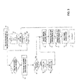
- Fig. 2 shows further details of one possible implementation of the ABMS in an automotive environment.
- Interaction with the battery is carried out by a "test layer”, wherein testing, preferably according to the Haung patents and application (referred to herein as the “LPR” or “DLPR” test) is performed, resulting in battery test data, including the internal resistance (or conductance, these being mathematically inverse, as noted).
- LPR low-density testing
- DLPR battery test data analysis
- the results of this analysis include determination of the several relevant measures of the battery capabilities, Ca, Ce, and Cm; from these SOC and SOH can be determined.
- the battery's average depth of discharge can also be determined, which is relevant in control of key-off loads; the number of discharge cycles can readily be tracked, and various alarms can be given by comparing Ca to various thresholds, as discussed above.
- the results from the Application Layer can be transmitted to an I/O Coms (i.e., Communications) layer, wherein the determined data can be used in performance of various functions.
- I/O Coms i.e., Communications
- data concerning the battery's SOH can be transmitted to the vehicle's on-board diagnostic (OBD) system, and used to provide a "replace battery" signal when appropriate.
- OBD on-board diagnostic
- ABS module typically a microprocessor-driven device implementing the calculations and control methods described above, or by the vehicle's “central processor/ECU (electronic control unit)".
- central processor/ECU electronic control unit
- Fig. 3 provides a schematic showing of an exemplary algorithm for such analysis, specifically for determining Ca on a regular basis, comparing it to Ce, determining Cm, and using these to provide an indication of anticipated battery life and instantaneous charge level, that is, effectively implementing the "fuel gauge" of Fig. 1(b) .
- a value x for an end of life factor feol, and a value y for a depth of discharge factor dd are assigned. These values control respectively the point at which the battery is deemed to be at the end of its useful life and the maximum depth to which it can be discharged without permanent damage.
- a typical value for feol would be 0.6, as in the example above, and for dd 0.5.
- the values for maximum capability Cm, the effective capability Ce, the available capability Ca, and a value n are initialized to zero, and T, a parameter controlling the frequency of measurement, is initially set to 60 seconds.
- step 44 testing, preferably according to the Huang patents and application referred to above is performed, yielding instantaneous values for the conductance C and voltage V of the battery.
- the instantaneous values C and V are compared to comparable values stored with respect to recently-performed similar measurements. As indicated in the next step 48, this comparison permits determination of the rate of charging or discharging, which has several implications. If the battery is discharging very slowly, this can be taken to indicate that it is not being used, e.g., if in a vehicle, that the vehicle is parked. It would be undesirable to perform testing too often under these circumstances, as the test itself draws some energy from the battery and could cause it to become fully discharged if performed too often. If the battery is being charged or is discharging rapidly, that is an indication that more frequent monitoring is in order. Accordingly, at step 50 T is adjusted accordingly.
- the determination is made as to whether the battery is charged. This can be done in any of several ways. For example, Ca, the available capability, can be compared to Ce, the effective capability; if Ca is within, for example, 2% of Ce, the battery can be taken to be fully charged. Alternatively, the battery can be taken to be fully charged if the rate of charge, determined in step 48, is less than a predetermined value. If the battery is thus determined to be charged, at step 54 Ce is set equal to Ca, a counter recording the number of charge/discharge cycles is incremented at step 54 by adding 1 to the value of n; thus recording the number of charge/discharge cycles may be useful in predicting battery life.
- the determination that the battery is charged may be implemented such that charging is only performed when the battery is discharged to a predetermined level.
- Cm the maximum capability
- Ce the maximum capability
- Cd representative of the minimum value to which the battery's capability is to be allowed to fall without damage, is set equal to fdd*Cm, thus relating Cd to the maximum capability of the battery.
- Ceol is similarly set to feol*Cm, allowing prediction of the battery's end-of-life based on Cm.
- Ce, Cm and Ceol can be compared in order to determine SOH, e.g., as Ce/Cm, and to estimate the remaining battery life, as Ceol/Ce.
- SOC can be determined as Ca/Ce
- Ca can be compared to Cd to ensure that the battery is not in danger of becoming unduly deeply discharged.
- the results of these steps can be communicated and used in any of a wide variety of ways.
- the results can be communicated to a user (e.g., by way of the fuel gauge described above, or by display of values for SOC and SOH on a computer screen implementing an instrument panel), provided to a vehicle status monitoring circuit (e.g., to cause a charging cycle to be initiated, or to indicate the desirability of maintenance), or transmitted to a remote monitoring location (e.g., in the fleet vehicle context, providing a status indication to a maintenance supervisory computer to schedule service).
- a remote monitoring location e.g., in the fleet vehicle context, providing a status indication to a maintenance supervisory computer to schedule service.
- the ABMS monitor according to the invention provides accurate, real-time SOC and SOH data can be used according to a further aspect of the invention to provide improved charge control, which can be expected to yield improved battery life and substantial economy.
- improved charge control can be used according to a further aspect of the invention to provide improved charge control, which can be expected to yield improved battery life and substantial economy.
- even so-called "smart" battery chargers simply monitor the voltage across their terminals and use this to control the rate of charge, so that it is reduced as the battery appears from this crude criterion to be approaching full charge.
- Clearly much more sophisticated control could be provided if a suitably programmed charger were provided with accurate SOC and SOH data. Given that it is known that over- or under-charging batteries decreases their useful life, it is self-evident that control of charging responsive to accurate measurements of these critical battery parameters can be expected to yield longer battery life.
- battery charging is inherently non-optimized according to present practices because the charger only “knows” the generic battery type (e.g., traditional "wet cell”, absorbed glass-mat (“AGM”), or valve-regulated lead acid (“VRLA”), or gel-cell), this information ordinarily being provided by the user upon charger installation. (Even according to the invention as now envisioned the user will still need to do so.)
- today's battery chargers even the “smart” or “three stage” chargers now available) are not provided with information concerning the capacity of the battery, nor how rapidly it can absorb and deliver energy. If the charger were able to adjust its output (current and voltage) based on the size of the battery, the charging rate could be increased where appropriate, while avoiding overcharge. Accordingly, charging would be faster and safer.
- a battery charger with charge rate control were provided with input from the ABMS battery monitor of the invention, such that the charger would "learn” the effective capacity (Ce) of the battery (and the maximum capacity Cm), the charger could then scale the output (current and voltage) to match the size and state of charge of the battery. For example, a charger capable of delivering current at a maximum of 10A might be operated at 3A to optimally and safely charge a small battery. Additionally, information as to the SOC of the battery, as compared to the effective capacity Ce, could be employed to manage the state transitions of the charger.
- typical ⁇ smart' chargers have a "Bulk charge” phase (constant current), an “Absorbtion charge” phase (constant voltage) and a “Float charge” phase (lower constant voltage.)
- the transitions are managed by monitoring voltage and current respectively.
- the current threshold used to manage the second transition is only appropriate for a battery of a specific size. By use of the ABMS technology, the charger would be able to detect the size and set the transition more appropriately for the size of the battery.
- the ABMS technology can detect that a battery is losing effective capacity and at some threshold or other trigger could control the charger to begin a desulfation process or an equalization process. (At present, these steps are to be initiated and controlled manually by the user; doubtless many users do not do so at the optimal times, if at all.)
- Present-day battery chargers to which the only input parameters are voltage and current, have no information concerning the capability of the battery or the manner in which it is changing, and so cannot automatically manage this process.
- the ABMS technology can do more than simply control the charge rate. If the technology is integrated, as it would typically be in a charger / inverter application, it can also tell the charger when to turn on and off based on actual charge level, rather than on voltage, which is often varying because of the attached load. For example, use of the ABMS technology would enable control of a generator so as to activate it when the batteries are actually discharged, rather than simply in response to detection of a low voltage, which might occur while fully-charged batteries are supplying a large momentary load.
- Fig. 4 shows a schematic block diagram of a typical system where a deep-cycle battery (or bank of discrete batteries) is used to supply one or more loads, incorporating a battery monitoring and control system according to this aspect of the invention.
- the paths of power distribution are shown by heavy lines, and signal measurement and control lines by lighter lines.
- the battery is shown at 20.
- Connected across its terminals 22, 24 are a charge level and battery life sensor section 26, a charger section 28, and a load management section 30.
- Load management section supplies power to the various loads 32a, 32b,.. 32n.
- the charge level and battery life sensor section 26 monitors the battery.
- charge level and battery life sensor section 26 determines the internal conductance of the battery 20 on a regular basis, and implements the ABMS technology disclosed above to use this information to determine the key parameters, e.g., Cm, Ce, and Ca, and from these SOH and SOC, for the battery 20.
- the key parameters e.g., Cm, Ce, and Ca
- Charger section 26 may comprise several sources of charge. For example, on a boat, charge may be obtained from an alternator on the propulsion engine(s), from a separate engine/generator "genset" unit, from a shore-powered battery charger, solar panels, a wind-driven generator, and the like. Depending on the needs of the battery, and the operational condition of the boat (for example, whether it is tied up at a dock and connected to shore power, motoring under its propulsion engine(s), or anchored) different sources of charge may be activated. For example, where the boat is anchored overnight, drawing power from battery 20 to supply various loads 32a, 32b, ... 32n via load management section 30, charger section 26 may comprise control circuitry to activate a genset responsive to detection that the battery SOC is dropping close to a preset value.
- a control line may be provided directly from charge level and battery life section 26 to load management section 30; this might be used to control disabling of one or more loads 32a, 32b,... 32n, e.g., in the event battery SOC is below a threshold and is not being resupplied through some flaw in charger section 28, in order to prevent excessively deep discharge of battery 20, which can cause permanent damage.
- charge level and battery life section 26 indicative of battery SOC and SOH could be employed in all aspects of control of a complex DC power distribution and battery charging system.
- the ABMS monitor as described above automatically adjusts the sampling rate of measuring the battery parameters.
- Operating a test circuit and actively testing for battery parameters on a consistent periodic basis can consume a significant amount of power over a long period of time (for example 90 days.)
- the efficiency of accessory circuits such as a battery monitoring circuit is very important and their power consumption must be carefully managed in order that the monitoring circuit does not itself drain the vehicle battery over time.
- a microprocessor comprised by the monitor of the invention compares one set of calculated key performance parameters to another set sampled at a different time, and determines whether the key performance parameters are changing rapidly or slowly. If the change is rapid, indicating that the battery is experiencing repetitive charge/discharge cycles as the vehicle is used, the microprocessor will increase the sampling rate, for example, performing the test once every 10 seconds or once every second. This is exemplified at steps 48 and 50 of Fig. 3 . If the change is slow, indicating that the battery is not being used, the microprocessor will decrease the sampling rate, to perhaps once every hour or once every week. In this way, the monitoring circuit can adjust its performance to optimize accuracy of results, while minimizing power consumption.
- the parameter measured is simply voltage; in another embodiment, the parameter measured is DC internal conductance.
- the parameters considered by the microprocessor to establish the test frequency could be a combination of these or any other parameters such as dynamic conductance or dynamic resistance.
- the test frequency can be set by an input from an external source such as a command from a wired or wirelessly connected network, for example a LIN, CANBUS, or IP network.
- test circuitry can be physically attached to the vehicle's battery wiring harness, such that the electrical connections of the battery sensor device are embedded in the battery terminal clamps.
- the device can provide additional benefits if some minimum threshold values are provided.
- These additional minimum threshold values could include a value such as a minimum DC internal conductance value, such that a defective battery, or a battery improperly sized for the application, would be identified very quickly, at the factory or just after the battery is installed.
- the monitoring device of the invention were provided as part of the vehicle as delivered, such minimum threshold values could be provided by the vehicle's on board computer system, or could be permanently stored in the sensor device memory. If the monitoring device of the invention were provided as an aftermarket accessory a nominal value for the battery's capability could be input by the user at installation, in any of a variety of ways known to those of skill in the art.
- Other attributes that could be stored in memory of the monitoring device of the invention are the number of battery charge / discharge cycles and the average depth of discharge as well as any other battery attribute that might be determined from one or a combination of the measured parameters.
- any of the above mentioned embodiments may be used in conjunction with traditional battery sensor technologies, such as current sensors, which may be implemented using shunts or Hall-effect coils, both well-known to the art.
- the monitoring devices of the invention can be used to establish very precise "time to empty” and "time to full charge” information, which may be of value to the user.
- the embodiments described herein generally refer to integrated monitoring devices having memory and calculation circuitry capable of processing raw data (voltage, temperature, time) in order to determine intermediate parameter(s) (DC internal resistance) and then compare this to stored data to determine summary information, the parameters of direct value to the user (battery capability, charge level, life cycle status, time to full or time to empty). It is also within the scope of the invention to provide effective communication between the sensors and an external information system, such that raw data (voltage, temperature, time) or the intermediate parameter(s) (DC internal resistance, or summary information) can be sent from the sensor device to a remote information system such as a vehicle central computer, or other processing unit remote from the sensor device.
- a remote information system such as a vehicle central computer, or other processing unit remote from the sensor device.
- the memory storing threshold and historical values, and the microprocessor performing calculations and implementing algorithms that convert the raw battery data into summary information such as charge levels, battery life, state of health, etc., are part of the remote system.
- the battery sensor can send summary information to the vehicle information system, or the battery sensor can send raw data to the vehicle information system and the vehicle information system can process the raw data into appropriate summary information.
- the summary information indicative of battery performance and capability can be used to control important vehicle systems. For example, it is common for vehicle batteries to become discharged if used to supply accessory loads (stereo, air conditioning) while the engine is shut off, possibly preventing restart of the engine.
- the monitoring circuitry can be integrated with the vehicle's starting circuitry to restart the main engine (or an auxiliary generator, if provided) so as to recharge the battery if the charge level reaches a predetermined threshold, or to shut down specific battery loads if the battery charge level becomes too low.
- a flag can be set in the vehicle diagnostic system informing the operator or a service technician.
- any of the previously described embodiments can output measured and calculated information to a separate display device or information system that is remote from the test circuitry of the monitoring system.
- Any analog or digital communication technology may be used to convey the information to a remote display or system.
- Such known communication technologies may be implemented using wired or non-wired connections; the latter may include radio communications, infra-red, or other technologies.
- the communication protocol may comprise any known or later-developed unidirectional or bidirectional analog, digital, serial or packet based communications protocol, including, but not limited to RS232, IP, TCP/IP, GPRS, USB, CAN, SNMP, LIN, WiFi, Zigbe, and others.
- the remote display or information system may also use the communication system to send a data request or command to the test circuitry of the battery monitor device, or to set or re-set a stored reference value or threshold value in the monitor device.
- Another embodiment of the invention addresses the needs of applications with more than one battery; for example a boat, recreational vehicle, or military vehicle will typically have an engine-starting battery and one or more bank(s) of deep-cycle batteries.
- each battery (or separately-connected battery bank) in the system is fitted with an appropriate battery monitoring device of the appropriate type described above.
- Each monitoring device monitors the corresponding battery as described above and uses a uni- or bi-directional communications link to communicate battery test data to one or more remote displays or information systems. Together the monitoring devices and displays of the system define a single specific battery monitoring network.
- the one or more monitoring devices and one or more displays of a network are configured to share information exclusively with monitor devices and remote displays in their specific network, such that many specific battery monitoring networks can operate in close proximity, without sharing data between or interfering with one another.
- each of the remote displays or information systems may be operated by a user to retrieve data from any one of the monitoring devices.
- Such a system may be used for example in a boat, recreational vehicle, or military vehicle application where multiple batteries, each used for different applications, can all be individually monitored each by a dedicated monitoring device, and the resulting data and critical battery information from each of many batteries may be displayed on a single display, or user interface conveniently located to the operator.
- Another embodiment of the invention comprises a specific battery monitoring network comprised of one or more battery monitoring devices and one more remote displays configured such that monitoring devices and displays may be flexibly added or removed from the specific battery monitoring network, thus creating an extensible specific battery monitoring system.
- An extensible network is useful where there are multiple batteries in a single system, or multiple systems each with a single battery whereby batteries or systems are entered into or removed from service on an ad hoc basis. Examples include a fleet of electric fork trucks used in a warehouse, or a boat with multiple banks of batteries. In both situations, batteries may be added to or removed from the network and the monitoring system reprogrammed to accommodate the alteration.
- Another embodiment of the invention is a specific battery monitoring network comprised of monitoring devices installed on one or more mobile vehicles, such as material handling equipment operating in a warehouse facility, or on a fleet of delivery or service trucks.
- Each of the monitoring devices communicates, e.g., battery condition data to a centralized information system remote from the vehicles.
- the information system is generally a stationary system for the continuous or intermittent collection of data from the monitoring devices, so that a fleet supervisor can determine when individual vehicle batteries need replacement.
- the battery monitoring devices may communicate substantially continuously with the remote information system; for example, in a warehouse, all vehicles with battery monitoring devices can send data continuously to the fixed position receiving station.
- the battery monitoring devices may accumulate and store monitoring data in their own memory and communicate all or a portion of the data to the information system periodically; for example, when a mobile vehicle with a monitoring device arrives back at its base at the end of the work day, the monitoring device can be interrogated and caused to download the data stored during the work day.
- An example of such an application is a fleet of delivery vehicles each having battery monitoring systems that will communicate their data wirelessly as they return to their depot and come into communication range with the fixed position information system. Again, such a system would be highly useful in identifying batteries in need of replacement, thus avoiding loss of time due to vehicle breakdowns.
- the data from the on-vehicle monitors can be communicated to a remote location, by way of the Internet or other known technique, so that the service decisions can be implemented other than at the specific location of the vehicles.
- the data provided by the battery monitoring device installed in a vehicle can be combined and transmitted together with other diagnostic information concerning the vehicle.
- OBD onboard diagnostic
- the battery monitoring devices described above can be enabled to store the OBD and battery condition information and transmit it to a remote location as desired, e.g., when the device is within range of the fixed position information system.
- the battery performance information as described earlier and also any diagnostic codes that were provided on the on-board diagnostic system can readily be transmitted.
- the fixed position information system which retrieves the information from the vehicles, can be connected to the Internet and thereby update a remote computer database with important diagnostic information from every vehicle in a large fleet every time the vehicle enters the communication range of the fixed position information system.
- the database can be configured to maintain a history of vehicle diagnostic information and to provide periodic reports and proactive critical alerts to maintenance managers, helping fleet managers focus precious resources on problems that otherwise would not have been discovered until a critical failure occurs.
- R resistance
- the internal resistance IR of a battery e.g., one installed in an automobile
- the internal resistance IR of the battery is very small.
- a device can be connected to a battery of unknown age or nominal capacity and used to predict its SOH.
- the actual flow of charge into and out of the battery can subsequently be monitored and used to track SOC over time.
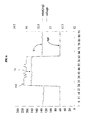
- FIG. 5 illustrates the discovery that is utilized by the method and instrument of the invention for evaluating the condition of a battery.
- Figs. 5 and 6 each plot voltage measured across a battery by a solid line, with the units on the right side of the diagram. (Note that these are "cleaned-up" plots of measured data, for clarity.) The internal conductance is shown by a dashed line, with the units in mhos on the left side of the diagram. Both diagrams represent measurements taken over a period of approximately 90 minutes, with measurements taken at one-minute intervals.
- Fig. 5 illustrates these measurements for a nearly new battery, in service for two months
- Fig. 6 shows comparable measurements for a battery of similar nominal characteristics that is relatively old, specifically one having been in service for twenty months.
- Fig. 9 discussed in detail below, is a comparable plot showing further detail relevant to additional aspects of the invention.
- Figs. 5 and 6 show plots of the voltage across and the conductance of a fully-charged battery, as measured while the battery is being charged, and before and after charging.
- the voltage Vg1 during charging is approximately 14.4, which takes place from minutes 29 through 51, and the voltage Vg2 is approximately 12.75 both before and after charging.
- the voltage Vg3 is approximately 14 during charging, from minutes 25 - 61, while the voltage Vg4 before and after charging is approximately 12.6.
- this discovery can be combined with the "self-learning" ability of a battery evaluation device operating in accordance with the discussion of Figs. 1 and 3 above to provide battery evaluation capabilities far beyond anything possible in the prior art.
- the conductance Cn of the fully-charged battery after charging is employed as the capability value Ce used to determine SOH according to the Fig. 1 and 3 technique.
- curve Cc has an average value of about 181 mho during charging
- curve Cn has an average value of about 170 mho after charging.
- Cn/Cc representing the actual condition of the test battery obtained by the method of the invention, is 0.944; expressed as a percentage, this is 94.4%. Knowing that this battery is relatively new, this value can be taken as SOHnominal, to which corresponding values for batteries of unknown condition may be compared.
- curve Cc has an average value of about 182 mho during charging
- curve Cn has an average value of about 130 mho after charging.
- Cn/Cc representing the actual condition of the test battery as evaluated according to the invention is thus 0.714 or, expressing this as a percentage
- SOHactual is 71.4 %.This can be compared to the corresponding value SOHnominal to determine whether the battery is usable; the value measured in the example would be taken to indicate that the battery was only marginally useful.
- a signal will be given to indicate that a used battery should be replaced with a new one if its measured internal resistance Cn is less than 60% of Cc; the exact value of the percentage is decided depending on the type of the battery to be measured.
- Cc is essentially identical for a new battery and a well-used battery.
- This fact is highly significant in application of the invention, as it means that Cc can be measured at any time during the lifetime of a battery, simply by charging the battery and measuring its conductance, and compared to Cn, the conductance measured after charging, to determine the relative condition of the battery. Accordingly, it is not required to input a value for Cc of a new battery, nor a value for SOHnominal.
- the technique of the invention for determining SOH of the battery can be applied to any fully-charged battery at any time without more information being provided.
- FIG. 7 shows the principal steps in the method of the invention for evaluating the condition, that is the state of health, or SOH, of a battery, responsive to the above discovery.
- a predetermined value i.e., SOHnominal
- the conductance of a fully-charged battery is measured while charging continues, and is expressed in mhos as Cc.
- Cc the conductance of the battery is measured after charging is complete, and is expressed in mhos as Cn.
- Cn is divided by Cc to obtain SOHactual as an indication of the actual condition of the battery. If a value for SOHnominal was provided in step 81, SOHactual can be compared thereto in step 85. In step 86 a warning can be issued if battery failure is imminent.
- FIG. 8 shows a more detailed flow chart with respect to the method of the FIG. 7 .
- a value SOHnominal corresponding to the SOH of a new battery may optionally be set.
- a charging device is used to charge the battery, and, when the battery is fully charged (determined as discussed further below), the conductance C of the battery is measured, expressed in mhos, and stored in memory. In order to improve the accuracy of the value, the measurement is preferably performed a plurality K of times and an average taken and stored as Cc.
- step 95 charging is stopped, and the conductance of the battery is measured, expressed in mhos, and stored in memory; again it is preferable that an average value be stored as Cn.
- step 96 Cn is compared to Cc to obtain a percentage value SOHactual indicative of the actual condition of the battery. If a value was provided for SOHnominal, it is compared in step 97 with SOHactual.
- step 98 a determination is made whether the battery is usable or not based on the comparison, or simply responsive to SOHactual. If the battery is not usable, an I/O device (e.g., a warning light) is instructed to issue a warning.
- an I/O device e.g., a warning light
- Cc will be measured repeatedly while the engine is running and Cn when the engine is shut off. As discussed below in connection with Fig. 9 , it will typically be preferred to delay measurement of Cn for a few minutes after charging ceases, to allow "surface charge" leading to erroneous readings to dissipate. If it is then determined that SOH has fallen to a point indicating incipient failure of the battery, a corresponding alarm signal can be given.
- Fig. 9 is a diagram displaying variation in voltage across a battery and its conductance over a period of some 400 minutes, as the battery is first discharged through a heavy load, is then charged, and is then quiescent.
- the conductance C is shown by a dashed line, in units of mho as indicated on the left side of the graph, and battery voltage V by a heavier line, in units of volts as indicated on the right side.
- the drawing is a "cleaned-up" version of actual data.
- the battery is first discharged by connection to a heavy load, from minutes 1 through 106.
- V and conductance C both drop rapidly as the battery becomes discharged.
- the load is removed and a charger connected.
- V rises rapidly from approximately 10 volts to 13.2 volts when the charger is initially connected, and then rises much more slowly, over a period of approximately two hours, to a final value of nearly 14.5 volts.
- the conductance C also initially rises rapidly when the charger is first connected, but thereafter rises in a non-linear fashion, eventually reaching a stable value Cc of approximately 210 mho.
- the battery may be taken to be fully charged when C reaches a relatively stable value, e.g., when the variation in a succession of measurements is less than an arbitrary value L.
- a relatively stable value e.g., when the variation in a succession of measurements is less than an arbitrary value L.
- L an arbitrary value
- the ABMS technique as described with respect to Figs. 1 and 3 is "self-learning" in the sense that a maximum capability value Cm is automatically stored and updated, such that the monitor of the invention "learns" the maximum capability of the associated battery; combined with ongoing measurements of voltage and conductance, this Cm value allows SOH to be determined for any battery, in substantially any condition, and thereafter allows its useful remaining life to be predicted accurately.
- Ca can also be measured regularly and compared to Ce to yield a value for SOC. Further, by measuring Cn after the battery has been charged, the device is “self-calibrating" as well.
- the self-learning and -calibration attributes of the present invention overcome significant shortcomings of the prior art because sensors made according to the present invention can be installed on a wide range of battery sizes, types, and ages in a wide range of use situations and very quickly can 'learn' the key attributes of the battery and begin reporting useful SOC and SOH information.
- a traditional "shunt” or “VIT” sensing circuit can be combined with data provided according to the invention to provide continuous, highly accurate SOC information.
- VIT sensors produce highly accurate current flow information, but have difficulty correlating that information to battery SOC over time without knowing other important unique information about the battery.
- Fig. 9A repeats the same curve C as in Fig. 9 , omits the curve V for clarity, and adds a solid charge/discharge curve indicating the integrated flow of charge into and out of the battery.
- Charge flow can be measured by a shunt, Hall-effect sensor, inductive coil, or other means well known to the art, and the integration carried out in the system microprocessor control unit (MCU)(discussed below in connection with Fig. 11 .)
- MCU system microprocessor control unit
- a value for SOC established when the battery is fully charged from time to time can be continually updated and maintained accurate.
- the integrated charge will vary linearly during discharge and charge, but the accuracy of the calculated value for SOC does not depend upon linearity nor constant rate of flow, as the flow is measured directly.
- a battery is a tank for water, of unknown initial capability Cm, but having a simple gauge indicating the degree to which it is filled. Over time its capability has decreased, as if filled to an unknown degree with gravel, such that its present capability Ce is also unknown.
- the tank is first filled, and its level Ce recorded. It is then gradually emptied while the quantity of water released is integrated. At some later time its relative level Ca is again recorded.
- Ca/Ce indicates the degree to which the tank has been emptied; if this is 50%, and ten gallons of water has been released, then Ce is 20 gallons. Henceforth, starting each time the tank is refilled, one can subtract the amount of water released from 20 gallons to determine the exact amount of water remaining.
- Fig. 10 shows a flowchart of the steps in an exemplary algorithm for performing this calculation. Many of the steps here are substantially identical to those in Fig. 3 and their description here will be abbreviated accordingly. It will further be appreciated that many modifications and variations are possible.
- steps 100 and 101 initialize the variables used.
- step 102 the conductance C and voltage V of a battery under test are measured. This may be accomplished using the LPR test disclosed in U.S. Patent Application Serial No. 11/984,669 , and summarized again below, or by another method for measuring C and V, if suitable. These are compared in step 103 to stored values Ca and Va, and their rate of change is determined in step 113; in step 114, this is used to set the interval T at which the process is repeated. Step 116 determines whether the battery is then fully charged and charging; if so, Cc is set equal to the measured value C in step 115.
- Cn is set equal to C
- Ci the value of the integrated current, as measured across a shunt or otherwise, as above
- control goes directly to block 104, where Cd (representing the maximum depth of discharge to be permitted) is set equal to fdd *Cc, and Ceol is set equal to feol*Cc.
- step 105 the current I through the shunt is measured and multiplied by the elapsed time T to yield an integrated value for the total energy flow, and Ci is updated accordingly.
- step l OSA which may be performed upon initialization of the device at installation, or from time to time during its use, a scale factor SF is determined for conversion of the value for the integrated flow of current Ci to values for capability, as typically determined responsive to measurements of the conductance of the battery.
- the scale factor SF can be determined as discussed below.
- Ci is compared to SF to determine the instantaneous value for SOC(current), that is, to derive a value for SOC responsive to measurement of the current flow Ci.
- step 107 SOC can be determined as a function of conductivity, e.g., to confirm the conversion value SF.
- step 108 Cn, Cc, and Ceol are compared to determine SOH.
- step 109 SOC and SOH are compared to alarm limits, and an alarm given at 110 if appropriate. Otherwise, the results may be displayed on an output device at step 111. The process is repeated after an interval T, as indicated by step 112.
- the process of the invention includes performance of an initialization step to determine the relation between the flow of charge and the change in conductance. For example, the Cn of a fully charged battery can be stored, and a value for Cdd determined as fdd*Cn. Thus Cdd corresponds to 0% SOC.
- the fully-discharged battery need then only be partially discharged, while the current flow is integrated and the change in conductance of the battery monitored; the amount of current flow corresponding to a discharge of 0% SOC can then be predicted. For example, if Cn were 200 MHO, and fdd were 0.5, Cdd would then be 100 MHO. Suppose a total current flow of 10 A was recorded while C dropped to 150 MHO. SOC would then be 100 - [(200 - 150)/(200 - 100)], or 50%; from this it will readily be seen that the total current required to discharge the battery from 100% SOC to 0% SOC would be 20 A. This establishes the scale factor SF to be employed thereafter with respect to that particular battery.
- SF is 5, i.e. multiply the measured current by 5 and subtract that number of mhos from Cc to obtain C, which is then compared to Cdd to yield SOC. Thereafter, each time the battery is known to be fully charged, SOC can be re-set to 100%, and current flow monitored thereafter to track SOC over time.
- FIG. 11 shows an electrical block diagram of an apparatus 160 for evaluating the condition of a battery according to the invention.
- the basic circuit and technique used for measuring the conductance of the battery is as disclosed in U.S. Patent Application Serial No. 11/984,669 .
- the apparatus 160 comprises a voltage-stabilizing circuit 161 for supplying a stable voltage to the apparatus 160 in operation, a MCU (microprocessor control unit) 162 for controlling the apparatus 160 and for measuring the voltage at several points in the circuit connected to MCU 162 at analog to digital (A/D) inputs, an known load resistance of value R 163, a transient current control circuit 165, and an I/O (input/output) unit 167.
- the I/O unit 167 can be implemented in a number of ways familiar to those of skill in the art, e.g. as one or more of a display, a keyboard input, a wireless communication device, and wireless access to the Internet.
- the apparatus 160 comprises a transient current control circuit 165 implemented as two parallel transistors Q1 and Q2, each representing a controllable load, connected so that either one or both of Q1 and Q2 can be caused to draw current from the battery B through a known resistance R 163.
- Large "transient" currents (that is, large currents drawn for a very short time, so as to limit the amount of power dissipated) are controllably drawn from the battery B to be evaluated by the first and second transistors, responsive to control signals from the MCU 162. If only Q1 is conductive, a reference load voltage V LR can be measured across R using connections 163B and 163D; then Q2 can be caused also to conduct.
- the Fig. 11 circuit is also shown connected to a charger G or other source of energy 170 by a switch SW1 171 operated responsive to an associated control line 168.
- the connection of the service load L 172 is also shown, as is a shunt resistance 174 with a pair of voltage-sensing connections 176 provided to measure the current flowing into or out of the battery B.
- the value of the conductance is then stored as Cc, and the charger is de-energized; after a time sufficient to allow the surface charge to dissipate (or after the measured voltage has stabilized, indicating dissipation of the surface charge), the value of the conductance is measured again and stored as Cn.
- SOH can then be determined by comparing Cn and Cc.
- SOC can then be tracked in future, by monitoring the current into and out of the battery, using voltage sensing leads 176 to measure the voltage drop across a shunt 174 of known resistance, and employing this to track changes in SOC. In order to provide an accurate measure of the remaining charge, an indication of the actual capacity of the battery (as opposed to the "relative" capacity given by SOH) can be derived.
- the I/O device can be controlled by the MCU, e.g., to provide an output indicating the SOH and SOC of the battery; for example the SOC can be displayed as a percentage value, or a value for the remaining amount of energy stored in the battery can be displayed.
Applications Claiming Priority (2)
| Application Number | Priority Date | Filing Date | Title |
|---|---|---|---|
| US93501707P | 2007-07-23 | 2007-07-23 | |
| US12/071,277 US7928735B2 (en) | 2007-07-23 | 2008-02-19 | Battery performance monitor |
Publications (3)
| Publication Number | Publication Date |
|---|---|
| EP2068161A2 true EP2068161A2 (fr) | 2009-06-10 |
| EP2068161A3 EP2068161A3 (fr) | 2011-06-22 |
| EP2068161B1 EP2068161B1 (fr) | 2018-09-05 |
Family
ID=40294727
Family Applications (1)
| Application Number | Title | Priority Date | Filing Date |
|---|---|---|---|
| EP08013201.2A Not-in-force EP2068161B1 (fr) | 2007-07-23 | 2008-07-22 | Moniteur de performance de la batterie |
Country Status (4)
| Country | Link |
|---|---|
| US (1) | US7928735B2 (fr) |
| EP (1) | EP2068161B1 (fr) |
| CN (2) | CN101354432B (fr) |
| TW (2) | TWI444639B (fr) |
Cited By (6)
| Publication number | Priority date | Publication date | Assignee | Title |
|---|---|---|---|---|
| US8473231B2 (en) | 2008-08-07 | 2013-06-25 | Research In Motion Limited | Systems and methods for monitoring deterioration of a rechargeable battery |
| DE102013201529A1 (de) | 2013-01-30 | 2014-07-31 | Ford Global Technologies, Llc | Verfahren und Vorrichtung zur Überwachung mindestens einer Traktionsbatterie eines Kraftfahrzeugs |
| EP2857855A4 (fr) * | 2012-05-31 | 2015-06-24 | Sanyo Electric Co | Procédé de contrôle et appareil de contrôle l'utilisant |
| DE102016214338A1 (de) * | 2016-08-03 | 2018-02-08 | Bayerische Motoren Werke Aktiengesellschaft | Verfahren und System zur Unterstützung bei der Wartung eines elektrisch angetriebenen Fahrzeugs |
| EP3686618A1 (fr) | 2019-01-28 | 2020-07-29 | Sandvik Mining and Construction Oy | Estimation de l'état de santé de batterie en ligne pendant le chargement |
| EP3977145A4 (fr) * | 2019-05-30 | 2023-02-15 | Cummins, Inc. | Procédé et système d'estimation d'une fin de vie d'un dispositif de stockage d'énergie rechargeable |
Families Citing this family (242)
| Publication number | Priority date | Publication date | Assignee | Title |
|---|---|---|---|---|
| GB0710524D0 (en) * | 2007-06-01 | 2007-07-11 | Lysanda Ltd | Improvements in and relating to engine monitoring |
| WO2009043640A1 (fr) * | 2007-09-26 | 2009-04-09 | Robert Bosch Gmbh | Procédé pour informer un conducteur sur la capacité de débiter une puissance minimale pouvant être requise d'un moteur électrique d'un véhicule |
| US20100292942A1 (en) * | 2009-05-18 | 2010-11-18 | Lonnie Calvin Golf | Embedded algorithms for vehicular batteries |
| US8581548B2 (en) * | 2009-12-28 | 2013-11-12 | 4 Peak Technology LLC | Integrated cell balancing system, method, and computer program for multi-cell batteries |
| US8437908B2 (en) * | 2008-03-10 | 2013-05-07 | 4 Peaks Technology Llc | Battery monitor system attached to a vehicle wiring harness |
| US20100217551A1 (en) * | 2009-02-25 | 2010-08-26 | Lonnie Calvin Goff | Embedded microprocessor system for vehicular batteries |
| US20090210736A1 (en) * | 2008-02-20 | 2009-08-20 | Lonnie Calvin Goff | Multi-function battery monitor system for vehicles |
| US20100179778A1 (en) * | 2009-01-15 | 2010-07-15 | Lonnie Calvin Goff | Embedded monitoring system for batteries |
| US8386199B2 (en) * | 2009-01-08 | 2013-02-26 | 4 Peaks Technology Llc | Battery monitoring algorithms for vehicles |
| US8284039B2 (en) * | 2008-03-05 | 2012-10-09 | Earthwave Technologies, Inc. | Vehicle monitoring system with power consumption management |
| JP4702859B2 (ja) * | 2008-04-11 | 2011-06-15 | 古河電気工業株式会社 | 蓄電池の状態検知方法 |
| US9851408B2 (en) * | 2008-06-05 | 2017-12-26 | Cadex Electronics Inc. | Methods and apparatus for battery testing |
| US8084996B2 (en) * | 2008-06-27 | 2011-12-27 | GM Global Technology Operations LLC | Method for battery capacity estimation |
| US8099206B2 (en) * | 2008-10-24 | 2012-01-17 | GM Global Technology Operations LLC | Combined evidence vehicle health monitoring |
| JP4770918B2 (ja) * | 2008-11-18 | 2011-09-14 | ソニー株式会社 | 電池パックおよび制御方法 |
| JP2010139260A (ja) * | 2008-12-09 | 2010-06-24 | Hitachi Ltd | 二次電池の余寿命推定システムおよび余寿命推定方法 |
| JP5310003B2 (ja) * | 2009-01-07 | 2013-10-09 | 新神戸電機株式会社 | 風力発電用鉛蓄電池制御システム |
| JP4983818B2 (ja) * | 2009-02-12 | 2012-07-25 | ソニー株式会社 | 電池パックおよび電池容量計算方法 |
| US8935112B2 (en) | 2009-02-17 | 2015-01-13 | Chargepoint, Inc. | System and method for managing electric vehicles |
| US8321727B2 (en) * | 2009-06-29 | 2012-11-27 | Sandisk Technologies Inc. | System and method responsive to a rate of change of a performance parameter of a memory |
| US20110048485A1 (en) * | 2009-09-02 | 2011-03-03 | Lonnie Calvin Goff | Integrated battery management system for vehicles |
| DE102009042656A1 (de) * | 2009-09-23 | 2011-03-24 | Bayerische Motoren Werke Aktiengesellschaft | Verfahren zur Steuerung bzw. Regelung mindestens eines den Alterungszustand eines elektrischen Energiespeichers beeinflussenden Betriebsparameters |
| CN102035010B (zh) | 2009-09-29 | 2013-05-01 | 凹凸电子(武汉)有限公司 | 电池单元均衡电路及方法 |
| US8339100B2 (en) | 2009-09-29 | 2012-12-25 | O2Micro Inc | Systems and methods for cell balancing |
| US20110082621A1 (en) * | 2009-10-02 | 2011-04-07 | Eric Berkobin | Method and system for predicting battery life based on vehicle battery, usage, and environmental data |
| TW201113542A (en) * | 2009-10-06 | 2011-04-16 | shun-chang Zhang | Detection platform for battery performance |
| US8415926B2 (en) * | 2009-10-19 | 2013-04-09 | Apple Inc. | In-situ battery health detector and end-of-life indicator |
| KR101030910B1 (ko) * | 2009-10-19 | 2011-04-22 | 에스비리모티브 주식회사 | 배터리 관리 시스템 및 그 구동 방법 |
| WO2011075080A1 (fr) * | 2009-12-17 | 2011-06-23 | Vestas Wind Systems A/S | Procédé et système d'estimation de la durée de service d'une batterie pour système d'énergie d'appoint d'une éolienne |
| KR101156533B1 (ko) * | 2009-12-23 | 2012-07-03 | 삼성에스디아이 주식회사 | 에너지 저장 시스템 및 이의 제어 방법 |
| US8928190B2 (en) * | 2009-12-31 | 2015-01-06 | Ultralife Corporation | System and method for activating an isolated device |
| US20110184903A1 (en) * | 2010-01-26 | 2011-07-28 | Liam-Yung Sung | Operation System For Providing Backup Batteries For Hybrid Vehicles And/Or Electric Vehicles And Method Thereof |
| US9134136B2 (en) * | 2010-01-26 | 2015-09-15 | Mitsubishi Electric Corporation | Navigation apparatus, vehicle information display apparatus, and vehicle information display system |
| NL2004279C2 (en) * | 2010-02-22 | 2011-08-23 | Epyon B V | System, device and method for exchanging energy with an electric vehicle. |
| JP5544923B2 (ja) * | 2010-02-24 | 2014-07-09 | セイコーエプソン株式会社 | 保護回路および電子機器 |
| US9046586B2 (en) * | 2010-03-29 | 2015-06-02 | Panasonic Intellectual Property Management Co., Ltd. | Method and device for diagnosing secondary battery degradation |
| US8427104B2 (en) * | 2010-04-22 | 2013-04-23 | The Raymond Corporation | Method of allocating batteries for use on specific industrial vehicles in a fleet |
| WO2011133863A2 (fr) * | 2010-04-22 | 2011-10-27 | Enerdel, Inc. | Contrôle du niveau de charge d'une batterie |
| US8791669B2 (en) | 2010-06-24 | 2014-07-29 | Qnovo Inc. | Method and circuitry to calculate the state of charge of a battery/cell |
| US10067198B2 (en) * | 2010-05-21 | 2018-09-04 | Qnovo Inc. | Method and circuitry to adaptively charge a battery/cell using the state of health thereof |
| US11397216B2 (en) | 2010-05-21 | 2022-07-26 | Qnovo Inc. | Battery adaptive charging using a battery model |
| US8638070B2 (en) | 2010-05-21 | 2014-01-28 | Qnovo Inc. | Method and circuitry to adaptively charge a battery/cell |
| US9142994B2 (en) | 2012-09-25 | 2015-09-22 | Qnovo, Inc. | Method and circuitry to adaptively charge a battery/cell |
| US11397215B2 (en) | 2010-05-21 | 2022-07-26 | Qnovo Inc. | Battery adaptive charging using battery physical phenomena |
| US10389156B2 (en) | 2010-05-21 | 2019-08-20 | Qnovo Inc. | Method and circuitry to adaptively charge a battery/cell |
| US8970178B2 (en) | 2010-06-24 | 2015-03-03 | Qnovo Inc. | Method and circuitry to calculate the state of charge of a battery/cell |
| US11791647B2 (en) * | 2010-05-21 | 2023-10-17 | Qnovo Inc. | Method and circuitry to adaptively charge a battery/cell |
| US20130015805A1 (en) * | 2010-06-04 | 2013-01-17 | Triune Ip Llc | Energy storage element link and monitor |
| US20110316545A1 (en) * | 2010-06-29 | 2011-12-29 | Rylan Ian Grant | Electronic Detection of Signatures |
| DE102010038646A1 (de) * | 2010-07-29 | 2012-02-02 | Robert Bosch Gmbh | Verfahren und Anordnung zum Abschätzen der Leistungsfähigkeit mindestens einer Batterieeinheit einer wiederaufladbaren Batterie |
| US8498830B2 (en) | 2010-08-31 | 2013-07-30 | Hewlett-Packard Development Company, L.P. | Testing of a battery of a computing device |
| US20120065909A1 (en) * | 2010-09-14 | 2012-03-15 | Research In Motion Corporation | Time dampened charging indicator |
| KR20120028472A (ko) * | 2010-09-15 | 2012-03-23 | 삼성전자주식회사 | 휴대용 단말기의 충전 장치 및 방법 |
| US9851412B2 (en) | 2010-11-09 | 2017-12-26 | International Business Machines Corporation | Analyzing and controlling performance in a composite battery module |
| DE102010062856A1 (de) * | 2010-12-10 | 2012-06-21 | Sb Limotive Company Ltd. | Verfahren zur Ermittlung von Betriebsparametern einer Batterie, Batteriemanagementsystem und Batterie |
| JP5307113B2 (ja) * | 2010-12-20 | 2013-10-02 | 古河電気工業株式会社 | 満充電検知装置および満充電検知方法 |
| KR101288122B1 (ko) * | 2011-01-03 | 2013-07-18 | 삼성에스디아이 주식회사 | 배터리 충전방법, 및 이를 적용한 배터리 팩 |
| US20130021037A1 (en) * | 2011-01-21 | 2013-01-24 | Liebert Corporation | Wireless portable battery capacity test system |
| US20120194130A1 (en) * | 2011-01-27 | 2012-08-02 | Research In Motion Limited | Power pack partial failure detection and remedial charging control |
| JP2012163434A (ja) * | 2011-02-07 | 2012-08-30 | Rohm Co Ltd | 電池残量の検出回路、検出方法およびそれを用いた電子機器 |
| EP2683052A4 (fr) * | 2011-03-04 | 2015-05-06 | Nec Corp | Système de contrôle de charge, procédé de charge et support d'enregistrement |
| US20130073235A1 (en) * | 2011-03-17 | 2013-03-21 | Isophi Bvba | Battery monitoring devices |
| US20120239325A1 (en) * | 2011-03-17 | 2012-09-20 | Sony Mobile Communications Ab | Battery capacity estimation |
| DE102011015746A1 (de) * | 2011-03-31 | 2012-10-04 | Li-Tec Battery Gmbh | Verfahren zur Steuerung und Handhabung von elektrochemischen Zellen bzw. von Batterien, elektrochemische Zelle und Batterie |
| US20120253713A1 (en) * | 2011-04-01 | 2012-10-04 | Continental Automotive Systems, Inc. | Estimating the capacity of a li-ion battery based on initial part of the discharge curve |
| US8872481B2 (en) | 2011-04-27 | 2014-10-28 | General Electric Company | Systems and methods for predicting battery power-delivery performance |
| US9060213B2 (en) * | 2011-05-24 | 2015-06-16 | Spireon, Inc. | Battery monitoring system |
| DE102011077448A1 (de) * | 2011-06-14 | 2012-12-20 | Robert Bosch Gmbh | Verfahren zum Abschätzen von Zustandsgrößen eines elektrischen Energiespeichers |
| US9535415B2 (en) * | 2011-07-20 | 2017-01-03 | Rockwell Automation Technologies, Inc. | Software, systems, and methods for mobile visualization of industrial automation environments |
| KR20130013101A (ko) * | 2011-07-27 | 2013-02-06 | 현대모비스 주식회사 | 배터리 센서 및 그 동작 방법 |
| JP2014052296A (ja) * | 2011-09-09 | 2014-03-20 | Gs Yuasa Corp | 監視装置 |
| CN102998625B (zh) * | 2011-09-09 | 2017-05-24 | 株式会社杰士汤浅国际 | 监视装置 |
| DE102011082854A1 (de) * | 2011-09-16 | 2013-03-21 | Siemens Aktiengesellschaft | Verfahren und Vorrichtung zum Bestimmen einer Moduldegradation einer Photovoltaikanlage |
| US8719195B2 (en) * | 2011-10-10 | 2014-05-06 | The Boeing Company | Battery adaptive learning management system |
| JP2013083612A (ja) * | 2011-10-12 | 2013-05-09 | Mitsumi Electric Co Ltd | 電池状態計測方法及び電池状態計測装置 |
| US20130158912A1 (en) * | 2011-12-15 | 2013-06-20 | Chung-Shan Institute of Science and Technology, Armaments, Bureau, Ministry of National Defence | Apparatus for Measuring the State of Health of a Cell Pack |
| CN102520366B (zh) * | 2011-12-23 | 2014-11-12 | 上海交通大学 | 电动车电池安全与健康评估系统及其方法 |
| TWI515995B (zh) * | 2012-01-06 | 2016-01-01 | 鴻海精密工業股份有限公司 | 電池充電系統及方法 |
| DE102012200508A1 (de) * | 2012-01-13 | 2013-07-18 | Robert Bosch Gmbh | Batteriesensor |
| US20130204560A1 (en) * | 2012-02-02 | 2013-08-08 | Ying-Che Lo | Gas Gauge Device |
| US9347995B2 (en) * | 2012-02-18 | 2016-05-24 | Johnson Controls Technology Company | System and method for detecting battery failure during a non-operating event |
| US20130245973A1 (en) * | 2012-03-16 | 2013-09-19 | Smartmed Usa Inc. | Apparatus, computer program, method, and system for acquiring and analyzing battery metrics |
| TWI469416B (zh) * | 2012-04-03 | 2015-01-11 | Quanta Comp Inc | 充電電池模組、電池供電之電子裝置、以及電池充電方法 |
| CN103376351A (zh) * | 2012-04-11 | 2013-10-30 | 雅马哈发动机株式会社 | 车辆用二次电池的低电压警示方法及其装置 |
| JP5677362B2 (ja) * | 2012-04-27 | 2015-02-25 | 本田技研工業株式会社 | 電源劣化判定装置 |
| WO2013168323A1 (fr) * | 2012-05-11 | 2013-11-14 | パナソニック株式会社 | Dispositif de gestion de batterie de stockage, procédé de gestion de batterie de stockage, et programme |
| JP6001334B2 (ja) * | 2012-05-31 | 2016-10-05 | ルネサスエレクトロニクス株式会社 | 半導体装置、バッテリ状態監視モジュール及び車輌システム |
| EP2672562B1 (fr) * | 2012-06-06 | 2018-08-08 | General Electric Company | Agencement et procédé pour déterminer les positions des mamelons d'un animal à traire |
| CN103515993A (zh) * | 2012-06-15 | 2014-01-15 | 凹凸电子(武汉)有限公司 | 均衡充电检测器、方法及电池管理系统 |
| JP5737232B2 (ja) * | 2012-07-12 | 2015-06-17 | トヨタ自動車株式会社 | 定置用蓄電池の余寿命判定装置 |
| CN102738871B (zh) * | 2012-07-20 | 2014-09-10 | 腾讯科技(深圳)有限公司 | 对移动设备进行充电处理的方法及系统 |
| KR101540553B1 (ko) * | 2012-08-02 | 2015-07-29 | 닛산 지도우샤 가부시키가이샤 | 무인 반송차의 충전 관리 시스템 및 충전 관리 방법 |
| EP2882064B1 (fr) * | 2012-08-02 | 2016-09-28 | Nissan Motor Co., Ltd. | Système de gestion de charge destiné à des véhicules de transport sans pilote et procédé de gestion de charge destiné à des véhicules de transport sans pilote |
| TWI463158B (zh) * | 2012-10-05 | 2014-12-01 | Sanyang Industry Co Ltd | 車用檢測裝置 |
| US9280859B2 (en) * | 2012-10-08 | 2016-03-08 | Toyota Motor Engineering & Manufacturing North America, Inc. | Enhanced vehicle onboard diagnostic system and method |
| US9619612B2 (en) | 2012-10-15 | 2017-04-11 | Battery Technology Holdings, Llc | Tester for equipment, apparatus, or component with distributed processing function |
| US9857430B2 (en) | 2012-10-15 | 2018-01-02 | Battery Technology Holdings, Llc | Tester for equipment, apparatus or component with distributed processing function |
| CN102928786B (zh) * | 2012-10-22 | 2016-01-20 | 宁波电业局 | 蓄电池容量估算方法及系统 |
| TWI474531B (zh) * | 2012-10-22 | 2015-02-21 | Dynapack Internat Technology Corp | 電池充電方法 |
| US9063018B1 (en) | 2012-10-22 | 2015-06-23 | Qnovo Inc. | Method and circuitry to determine temperature and/or state of health of a battery/cell |
| US9267997B2 (en) | 2012-10-25 | 2016-02-23 | Bayerische Motoren Werke Aktiengesellschaft | Systems and methods to determine the condition of a battery |
| TWI580153B (zh) * | 2012-11-13 | 2017-04-21 | 電池監控系統 | |
| DE102012111591A1 (de) | 2012-11-29 | 2014-06-05 | Phoenix Contact Gmbh & Co. Kg | Verfahren und Vorrichtung zum Überwachen der Funktionsfähigkeit eines Akkumulators |
| CN103852725B (zh) * | 2012-11-30 | 2018-05-01 | 凹凸电子(武汉)有限公司 | 用于估算电池剩余容量的设备、方法及系统 |
| WO2014088325A1 (fr) * | 2012-12-04 | 2014-06-12 | 주식회사 엘지화학 | Procédé et dispositif permettant d'estimer la profondeur de décharge d'une batterie secondaire |
| US9077181B2 (en) * | 2013-01-11 | 2015-07-07 | GM Global Technology Operations LLC | Battery section balancing methods and systems |
| JP5708668B2 (ja) * | 2013-01-18 | 2015-04-30 | トヨタ自動車株式会社 | 蓄電システム |
| USD820204S1 (en) | 2013-01-25 | 2018-06-12 | Aviation Battery Systems Llc | Portable ground power unit |
| US20140210399A1 (en) | 2013-01-25 | 2014-07-31 | Pylon Aviation Services Llc | Portable electric power source for aircraft |
| US9316694B2 (en) * | 2013-02-12 | 2016-04-19 | Johnson Controls Technology Company | Battery monitoring system with time-based diagnostic activation |
| GB2510821B (en) * | 2013-02-13 | 2015-08-19 | Jaguar Land Rover Ltd | Charging Method |
| US9440544B2 (en) | 2013-03-15 | 2016-09-13 | Columbia Insurance Company | Battery management system and method |
| US20160172876A1 (en) * | 2014-12-15 | 2016-06-16 | Yardarm Technologies, Inc. | Charger for firearm electronics |
| US9461492B1 (en) | 2013-04-19 | 2016-10-04 | Qnovo Inc. | Method and circuitry to adaptively charge a battery/cell using a charge-time parameter |
| KR102062706B1 (ko) * | 2013-08-27 | 2020-02-20 | 삼성에스디아이 주식회사 | 배터리 팩 및 이를 제어하는 방법 |
| DE102013221192A1 (de) * | 2013-10-18 | 2015-04-23 | Robert Bosch Gmbh | Verfahren und Vorrichtung zum Einstellen einer Maximal-Entladetiefe eines Energiespeichers für eine Zeitperiode |
| JP6260192B2 (ja) * | 2013-10-21 | 2018-01-17 | 三菱自動車工業株式会社 | バッテリーパック |
| US20150221994A1 (en) * | 2014-02-06 | 2015-08-06 | Derek Ziemian | Calibration Shunt |
| US10910681B2 (en) * | 2014-02-24 | 2021-02-02 | Ravensafe, LLC | Portable renewable energy power system |
| TWI536706B (zh) | 2014-03-11 | 2016-06-01 | 登騰電子股份有限公司 | 智慧型電源轉接器及其供電控制方法 |
| KR102177721B1 (ko) * | 2014-03-20 | 2020-11-11 | 현대모비스 주식회사 | 배터리팩 열화 상태 추정 장치 및 방법 |
| US9740258B2 (en) * | 2014-03-24 | 2017-08-22 | Intel Corporation | Hold-up energy storage and management |
| TWI616667B (zh) * | 2014-04-01 | 2018-03-01 | 鴻海精密工業股份有限公司 | 電池健康狀態的估算方法及其裝置 |
| FR3020614B1 (fr) * | 2014-04-30 | 2016-04-15 | Renault Sa | Procede et dispositif de surveillance d'une batterie electrique de vehicule |
| US9956887B2 (en) | 2014-06-16 | 2018-05-01 | Ford Global Technologies, Llc | Batter capacity degradation indication |
| US10574079B1 (en) | 2014-06-20 | 2020-02-25 | Qnovo Inc. | Wireless charging techniques and circuitry for a battery |
| US9735599B2 (en) * | 2014-06-30 | 2017-08-15 | Stmicroelectronics S.R.L. | Battery charger including correction device to correct control signals for supply switching circuit |
| US9550429B2 (en) * | 2014-08-07 | 2017-01-24 | Cummins, Inc. | Systems and methods for management of fleet batteries |
| KR102318789B1 (ko) * | 2014-09-02 | 2021-10-28 | 삼성전자 주식회사 | 배터리 충전 관리 방법 및 이를 구현하는 전자 장치 |
| US10479298B2 (en) * | 2014-09-08 | 2019-11-19 | Mahindra Electric Mobility Limited | Intelligent determination and usage of energy in energy systems |
| JP5880649B1 (ja) * | 2014-09-08 | 2016-03-09 | 日清紡ケミカル株式会社 | 燃料電池セパレータ |
| DE102014220079A1 (de) * | 2014-10-02 | 2016-04-07 | Robert Bosch Gmbh | Verfahren zur Kalibrierung eines Sensors eines Batteriemanagementsystems |
| TWI541525B (zh) | 2014-12-10 | 2016-07-11 | 大同股份有限公司 | 電池電量估測裝置及其估測方法 |
| TWI542115B (zh) | 2014-12-10 | 2016-07-11 | 大同股份有限公司 | 充電裝置及其充電方法 |
| JP6516091B2 (ja) | 2014-12-25 | 2019-05-22 | 三菱自動車工業株式会社 | 電動車両の充電量表示装置 |
| CN104502856B (zh) * | 2014-12-26 | 2015-09-30 | 骐俊通联(厦门)科技有限公司 | 一种检测车辆蓄电池寿命的方法和系统 |
| DE102015001050A1 (de) * | 2015-01-29 | 2016-08-04 | Man Truck & Bus Ag | Verfahren und Vorrichtung zur Steuerung und/oder Regelung mindestens eines einen Alterungszustand eines elektrischen Energiespeichers beeinflussenden Betriebsparameters des elektrischen Energiespeichers |
| US9776635B2 (en) * | 2015-02-09 | 2017-10-03 | Ford Global Technologies, Llc | Apparatus and method to maximize vehicle functionality and fuel economy with improved drivability during engine auto stop-start operations |
| WO2016132353A1 (fr) * | 2015-02-17 | 2016-08-25 | Siros Energy Ltd | Système de commande à distance intelligent permettant de charger et d'utiliser des batteries rechargeables dans des véhicules de transport |
| US10338153B2 (en) * | 2015-03-03 | 2019-07-02 | Samsung Electronics Co., Ltd. | Method and apparatus for automatically estimating remaining useful life (RUL) of battery in real time |
| US10935606B2 (en) | 2015-03-12 | 2021-03-02 | Omron Corporation | Excess/deficiency determination device, method for controlling same, control program, and recording medium |
| JP6504246B2 (ja) * | 2015-03-12 | 2019-04-24 | オムロン株式会社 | 情報処理装置、その制御方法、制御プログラム、および記録媒体 |
| DE102015205171A1 (de) | 2015-03-23 | 2016-09-29 | Siemens Aktiengesellschaft | Verfahren und Vorrichtung zum Laden oder Entladen eines Energiespeichers |
| DE102015206878B4 (de) | 2015-04-16 | 2024-03-14 | Ford Global Technologies, Llc | Verfahren zum Betrieb einer Batterie |
| CN104882931B (zh) * | 2015-05-27 | 2017-01-25 | 沈阳航空航天大学 | 航空电源电池管理系统及其方法 |
| US10295611B2 (en) | 2015-06-09 | 2019-05-21 | Premier Technologies, Ltd. | Efficient battery tester |
| US20180131049A1 (en) * | 2015-06-14 | 2018-05-10 | Smithville Labs, LLC | Apparatus and method for charging valve regulated lead acid batteries |
| JP6583718B2 (ja) * | 2015-07-22 | 2019-10-02 | スズキ株式会社 | バッテリの劣化判定装置 |
| US20170033572A1 (en) * | 2015-07-27 | 2017-02-02 | Robert Bosch Gmbh | Capacity estimation in a secondary battery |
| US9800073B2 (en) * | 2015-08-20 | 2017-10-24 | International Business Machines Corporation | Modeling a change in battery degradation |
| US10663529B1 (en) * | 2015-09-25 | 2020-05-26 | Amazon Technologies, Inc. | Automatic battery charging |
| US9932951B2 (en) * | 2015-10-08 | 2018-04-03 | Jeffrey S. Lynch | Engine start stop system based on programmable battery voltage levels |
| EP3378114A4 (fr) | 2015-11-16 | 2019-08-07 | Hheli, LLC | Matériaux oxydes métalliques acidifiés fonctionnalisés en surface synthétisés pour applications en stockage d'énergie, en catalyse, en photovoltaïque et aux capteurs |
| KR20170076411A (ko) * | 2015-12-24 | 2017-07-04 | 삼성전자주식회사 | 배터리 관리 장치 및 방법 |
| US10569660B2 (en) * | 2016-02-26 | 2020-02-25 | Ford Global Technologies, Llc | Systems and methods for battery state-of-health monitoring |
| US9840161B2 (en) | 2016-03-10 | 2017-12-12 | Ford Global Technologies, Llc | Circuit and method for detection of battery cell degradation events |
| US10701492B2 (en) | 2016-03-18 | 2020-06-30 | Sonova Ag | Method of monitoring state of health of a battery of a hearing device, a hearing device, a hearing device and an arrangement comprising a hearing device |
| AT518595B1 (de) * | 2016-04-18 | 2018-10-15 | Avl Ditest Gmbh | Bestimmung der elektrischen Kontaktierung |
| DE102016107419A1 (de) * | 2016-04-21 | 2017-10-26 | Beckhoff Automation Gmbh | Konzept zum Speichern von Energie |
| US10656233B2 (en) | 2016-04-25 | 2020-05-19 | Dynexus Technology, Inc. | Method of calibrating impedance measurements of a battery |
| CA3024096A1 (fr) | 2016-05-13 | 2017-11-16 | Carter-Hoffmann LLC | Chariot de rechauffage transportable |
| US20180065577A1 (en) * | 2016-09-06 | 2018-03-08 | Hyundai Motor Company | Optimization method and apparatus of power control logic for entering into isg mode |
| US10650621B1 (en) | 2016-09-13 | 2020-05-12 | Iocurrents, Inc. | Interfacing with a vehicular controller area network |
| US10099569B2 (en) * | 2016-09-29 | 2018-10-16 | GM Global Technology Operations LLC | Adaptive system and method for optimizing a fleet of plug-in vehicles |
| US20180276913A1 (en) * | 2016-09-30 | 2018-09-27 | Faraday&Future Inc. | Remote vehicle network monitoring and failure prediction system |
| KR101846913B1 (ko) * | 2016-11-01 | 2018-04-09 | 현대자동차 주식회사 | 하이브리드 차량의 배터리 충전 제어 장치 및 충전 제어 방법 |
| US10700349B2 (en) | 2016-11-15 | 2020-06-30 | HHeLI, LLC | Surface-functionalized, acidified metal oxide material in an acidified electrolyte system or an acidified electrode system |
| TWI609191B (zh) * | 2016-11-21 | 2017-12-21 | Battery health status estimating device and method | |
| US10302709B2 (en) | 2016-11-30 | 2019-05-28 | Cadex Electronics Inc. | Battery state-of-health determination using multi-factor normalization |
| TWI597510B (zh) * | 2016-12-23 | 2017-09-01 | Chen Tech Electric Mfg Co Ltd | Battery Life Cycle Prediction System and Method |
| US10672199B2 (en) * | 2017-01-18 | 2020-06-02 | Ford Global Technologies, Llc | Method for monitoring component life |
| CN108569144B (zh) * | 2017-03-13 | 2020-06-02 | 宁德时代新能源科技股份有限公司 | 应用于电动客车的电池防失效切断系统 |
| EP3610526A4 (fr) | 2017-04-10 | 2020-12-16 | Hheli, LLC | Batterie dotée de nouveaux éléments |
| CA3062840C (fr) | 2017-05-17 | 2023-01-03 | Paige L. Johnson | Batterie a cathode acidifiee et anode au lithium |
| US10913443B2 (en) * | 2017-05-22 | 2021-02-09 | Ford Global Technologies, Llc | Powertrain control based on auxiliary battery characteristics |
| CN107271906B (zh) * | 2017-05-31 | 2019-10-18 | 宁德时代新能源科技股份有限公司 | 电池包健康度估算方法和装置 |
| US10400733B2 (en) | 2017-06-02 | 2019-09-03 | Ford Global Technologies, Llc | Vehicle battery control systems and method |
| US10978731B2 (en) | 2017-06-21 | 2021-04-13 | HHeLI, LLC | Ultra high capacity performance battery cell |
| US10921381B2 (en) | 2017-07-28 | 2021-02-16 | Northstar Battery Company, Llc | Systems and methods for monitoring and presenting battery information |
| CN109383324B (zh) * | 2017-08-10 | 2023-07-18 | 罗伯特·博世有限公司 | 用于充电管理的方法和装置、充电设备和机器可读介质 |
| US10818392B1 (en) * | 2017-08-10 | 2020-10-27 | Enovate Medical, Llc | Battery and workstation monitoring system and display |
| GB2568461B (en) * | 2017-11-01 | 2020-04-22 | Swanbarton Ltd | A Battery charger system and method |
| CN107577325A (zh) * | 2017-11-10 | 2018-01-12 | 郑州云海信息技术有限公司 | 一种基于bbu硬件的自适应管理系统和方法 |
| KR102467224B1 (ko) * | 2017-11-13 | 2022-11-14 | 현대자동차주식회사 | 차량용 전자 장치, 내부 저항 결정 방법 및 상기 차량용 전자 장치를 포함하는 차량 |
| JP6811698B2 (ja) * | 2017-11-21 | 2021-01-13 | 株式会社クボタ | 作業車及び作業車管理システム |
| JP6927001B2 (ja) * | 2017-12-06 | 2021-08-25 | トヨタ自動車株式会社 | 情報処理装置、情報処理方法および情報処理システム |
| KR102441505B1 (ko) * | 2017-12-11 | 2022-09-07 | 현대자동차주식회사 | 전기 자동차의 배터리 충전 방법 |
| CN109921141A (zh) * | 2017-12-12 | 2019-06-21 | Bgt材料有限公司 | 高功率电池或电容器模块 |
| DE102018202010A1 (de) * | 2018-02-08 | 2019-08-08 | Volkswagen Aktiengesellschaft | Verfahren zur Vorhersage einer bevorstehenden Beschädigung einer Verbindungsstelle zwischen zwei elektrischen Leitern in einem Kraftfahrzeugbordnetz, Vorrichtung und Kraftfahrzeug |
| CN108448180B (zh) * | 2018-04-10 | 2024-01-30 | 中国船舶重工集团公司第七0四研究所 | 一种船舶电池管理系统 |
| US11186201B2 (en) * | 2018-04-13 | 2021-11-30 | Honeywell International Inc. | Calculate lifetime of a battery based on battery use data from multiple network connected electric vehicles |
| DE102018206414A1 (de) * | 2018-04-25 | 2019-10-31 | Audi Ag | Verfahren zum Ermitteln einer einen Zustand einer Kraftfahrzeugbatterie betreffenden Größe, Zähler-Einrichtung und Kraftfahrzeug |
| KR102258821B1 (ko) * | 2018-04-30 | 2021-05-31 | 주식회사 엘지에너지솔루션 | 이차 전지 테스트 장치 및 방법 |
| US10608455B2 (en) | 2018-05-18 | 2020-03-31 | Sling Media Pvt. Ltd. | Quick battery charging with protection based on regulation relative state of charge |
| US10790844B2 (en) * | 2018-06-21 | 2020-09-29 | Lear Corporation | Sensor measurement verification in quasi real-time |
| WO2020003841A1 (fr) * | 2018-06-27 | 2020-01-02 | パナソニックIpマネジメント株式会社 | Dispositif de surveillance de batterie, circuit intégré et système de surveillance de batterie |
| EP3591413B1 (fr) * | 2018-07-03 | 2023-08-30 | Electricité de France | Procédé pour évaluer l'état de santé d'une batterie électrique |
| DE102018213523A1 (de) * | 2018-08-10 | 2020-02-13 | Volkswagen Aktiengesellschaft | Vorrichtung, Ladesäule sowie Verfahren zur Erfassung des Zustands einer Kraftfahrzeug-Batterie |
| KR102586447B1 (ko) * | 2018-08-20 | 2023-10-06 | 현대자동차주식회사 | 충전 상태 표시 제어기 |
| JP7410934B2 (ja) * | 2018-09-10 | 2024-01-10 | ヒーリー、エルエルシー | 超大容量高性能電池セルの使用方法 |
| US11110816B2 (en) * | 2018-09-18 | 2021-09-07 | GUY Thomas RINI | Condition based maintenance (CBM) of a vehicle primary electrical system |
| US10978883B2 (en) * | 2018-09-19 | 2021-04-13 | International Business Machines Corporation | Predictive rechargeable battery management system |
| KR102569897B1 (ko) * | 2018-10-08 | 2023-08-23 | 현대자동차주식회사 | 배터리 진단방법 및 장치 |
| GB201820073D0 (en) * | 2018-12-10 | 2019-01-23 | Tomtom Telematics Bv | Vehicle battery monitoring |
| US11899069B2 (en) * | 2018-12-21 | 2024-02-13 | Cummins Inc. | SOC and SOH co-estimation systems and methods for electric vehicles |
| AT522520B1 (de) * | 2019-04-17 | 2021-06-15 | Avl List Gmbh | Verfahren für eine Kontrolle eines Schutzverfahrens für den Schutz einer Elektrode einer Batterievorrichtung |
| US20220234469A1 (en) * | 2019-07-01 | 2022-07-28 | Volvo Truck Corporation | Improved management of an energy storage system of a vehicle |
| KR20210029878A (ko) * | 2019-09-06 | 2021-03-17 | 주식회사 엘지화학 | 배터리 관리 장치, 배터리 관리 방법, 배터리 팩 및 전기 차량 |
| US11223225B2 (en) | 2019-09-09 | 2022-01-11 | Deere & Company | Intelligent starting and charging system and method |
| US11063448B2 (en) * | 2019-09-16 | 2021-07-13 | Zebra Technologies Corporation | Methods and system for dynamically modifying charging settings for a battery assembly |
| CN112213649B (zh) * | 2019-10-31 | 2023-05-23 | 蜂巢能源科技有限公司 | 构建开路电压曲线的方法及系统 |
| US11221368B2 (en) * | 2019-11-08 | 2022-01-11 | Verifone, Inc. | Systems and methods for determining battery capacity in portable electronic devices |
| TWI744721B (zh) * | 2019-11-19 | 2021-11-01 | 廣達電腦股份有限公司 | 電池裝置及其控制方法 |
| FR3105433B1 (fr) * | 2019-12-20 | 2022-01-14 | Psa Automobiles Sa | Procédé de diagnostic pour une batterie de véhicule |
| CN111123137B (zh) * | 2019-12-24 | 2022-03-08 | 中创新航科技股份有限公司 | 电池组的soc和soh的估算方法 |
| JP6933270B2 (ja) * | 2020-01-10 | 2021-09-08 | トヨタ自動車株式会社 | 評価治具 |
| US11422102B2 (en) | 2020-01-10 | 2022-08-23 | Dynexus Technology, Inc. | Multispectral impedance measurements across strings of interconnected cells |
| WO2021145881A1 (fr) | 2020-01-16 | 2021-07-22 | Hewlett-Packard Development Company, L.P. | Profil utilisateur basé sur une mesure de batterie |
| JP6887700B1 (ja) * | 2020-01-20 | 2021-06-16 | 東洋システム株式会社 | 電池性能評価装置、電子機器、充電器および電池性能評価方法 |
| CN111261905B (zh) * | 2020-01-21 | 2023-03-14 | 西安理工大学 | 一种单液流电池电量的实时监控方法 |
| US11519969B2 (en) | 2020-01-29 | 2022-12-06 | Dynexus Technology, Inc. | Cross spectral impedance assessment for cell qualification |
| CN113298278B (zh) * | 2020-02-19 | 2023-12-05 | 硕天科技股份有限公司 | 具有自我健康状态预测功能的电力设备及其自我健康状态预测方法以及云端服务器 |
| CN111273181A (zh) * | 2020-02-28 | 2020-06-12 | 苏州浪潮智能科技有限公司 | 电池备电单元监测方法、装置、服务器及可读存储介质 |
| US11762031B2 (en) * | 2020-08-31 | 2023-09-19 | Medtronic, Inc. | Electrochemical cell state of health detection |
| TWI749835B (zh) * | 2020-10-29 | 2021-12-11 | 國立中央大學 | 電池診斷裝置、方法及其電腦程式產品 |
| CN112505567A (zh) * | 2020-10-30 | 2021-03-16 | 武汉蔚来能源有限公司 | 电池健康状态评估系统 |
| CN112485691B (zh) * | 2020-10-30 | 2022-10-21 | 傲普(上海)新能源有限公司 | 一种锂离子电池的soh估算方法 |
| US11614492B2 (en) * | 2020-11-02 | 2023-03-28 | Semiconductor Components Industries, Llc | Methods and apparatus for a battery |
| GB2600757A (en) * | 2020-11-09 | 2022-05-11 | Horiba Mira Ltd | Battery performance optimisation |
| US11906596B2 (en) * | 2020-12-24 | 2024-02-20 | Mediatek Inc. | System-side battery health gauge and methods |
| CN112765726A (zh) * | 2020-12-31 | 2021-05-07 | 东软睿驰汽车技术(沈阳)有限公司 | 一种寿命预测方法及装置 |
| CN113071364B (zh) * | 2021-04-01 | 2022-07-29 | 上海钧正网络科技有限公司 | 电池调度评估方法、装置及计算机可读存储介质 |
| CN113002364A (zh) * | 2021-04-22 | 2021-06-22 | 一汽解放汽车有限公司 | 电池充电截止电荷状态确定方法、装置、电子设备及介质 |
| CN113484783B (zh) * | 2021-05-31 | 2024-03-26 | 北京海博思创科技股份有限公司 | 电池soh检测方法、装置、系统、介质及程序产品 |
| CN113500974B (zh) * | 2021-08-21 | 2022-12-13 | 深圳市奥拓普科技有限公司 | 一种电源管理控制方法以及系统 |
| US11443569B1 (en) * | 2021-10-30 | 2022-09-13 | Beta Air, Llc | Systems and methods for battery management for a vehicle |
| US11462917B1 (en) | 2021-12-10 | 2022-10-04 | NDSL, Inc. | Methods, systems, and devices for maintenance and optimization of battery cabinets |
| US11689048B1 (en) | 2021-12-10 | 2023-06-27 | NDSL, Inc. | Methods, systems, and devices for maintenance and optimization of battery cabinets |
| FR3130389B1 (fr) * | 2021-12-14 | 2023-11-24 | Commissariat Energie Atomique | Méthode de diagnostic et de prédiction de durée de vie de batteries au plomb, notamment destinées au stockage d'énergie de secours. |
| WO2023133270A1 (fr) * | 2022-01-06 | 2023-07-13 | Electric Hydrogen Co. | Atténuation de court-circuit électrique dans électrolyseur d'eau à membrane d'électrolyte polymère |
| US11527786B1 (en) * | 2022-03-28 | 2022-12-13 | Eatron Technologies Ltd. | Systems and methods for predicting remaining useful life in batteries and assets |
| CN117368746B (zh) * | 2023-12-07 | 2024-03-29 | 深圳海辰储能科技有限公司 | 电池荷电状态的修正方法及装置、设备、存储介质 |
Citations (25)
| Publication number | Priority date | Publication date | Assignee | Title |
|---|---|---|---|---|
| US3852732A (en) | 1973-03-30 | 1974-12-03 | Westinghouse Electric Corp | Solid state universal battery monitor |
| US3909708A (en) | 1974-01-02 | 1975-09-30 | Keith S Champlin | Electronic battery testing device |
| US4193026A (en) | 1976-04-18 | 1980-03-11 | Curtis Instruments, Inc. | Method and apparatus for measuring the state of charge of a battery by monitoring reductions in voltage |
| US4912416A (en) | 1988-06-06 | 1990-03-27 | Champlin Keith S | Electronic battery testing device with state-of-charge compensation |
| US5027294A (en) | 1989-01-27 | 1991-06-25 | Zenith Data Systems Corporation | Method and apparatus for battery-power management using load-compensation monitoring of battery discharge |
| US5130699A (en) | 1991-04-18 | 1992-07-14 | Globe-Union, Inc. | Digital battery capacity warning device |
| US5193067A (en) | 1988-12-05 | 1993-03-09 | Nippondenso Co., Ltd. | Battery condition detecton apparatus |
| US5381096A (en) | 1992-04-09 | 1995-01-10 | Hirzel; Edgar A. | Method and apparatus for measuring the state-of-charge of a battery system |
| US5721688A (en) | 1996-09-06 | 1998-02-24 | Madill Technologies, Inc. | Apparatus and method for electrical system measurements including battery condition, resistance of wires and connections, total electrical system quality and current flow |
| US5751217A (en) | 1996-02-01 | 1998-05-12 | Motorola, Inc. | Method and apparatus for assessing available battery life in a rechargeable battery |
| US5764469A (en) | 1995-07-11 | 1998-06-09 | Tas Distributing Co., Inc. | Apparatus for protecting eletronic devices in a vehicle's electronic system and for preventing discharge of the vehicle's battery |
| US5828218A (en) | 1993-06-30 | 1998-10-27 | Honda Giken Kogyo Kabushiki Kaisha | Method of estimating residual capacity of battery |
| US5900734A (en) | 1997-12-22 | 1999-05-04 | Munson; Edward J | Low battery voltage detection and warning system |
| US6072300A (en) | 1997-11-14 | 2000-06-06 | Nissan Motor Co., Ltd. | Battery state diagnostic apparatus for battery set and battery module charger/discharger |
| US6201373B1 (en) | 1999-05-26 | 2001-03-13 | Yazaki Corporation | Battery remaining capacity measuring apparatus suitable for hybrid car |
| US6249106B1 (en) | 2000-09-21 | 2001-06-19 | Delphi Technologies, Inc. | Apparatus and method for maintaining a threshold value in a battery |
| US6424157B1 (en) | 1998-07-20 | 2002-07-23 | Alliedsignal, Inc. | System and method for monitoring a vehicle battery |
| US6531875B2 (en) | 2000-12-08 | 2003-03-11 | Yazaki Corporation | Vehicle battery's open circuit voltage estimating method and a system therefor |
| US20030067221A1 (en) | 2001-10-09 | 2003-04-10 | Delphi Technologies, Inc. | Controller input voltage regulation by actuator power modulation |
| US6633165B2 (en) | 1997-11-03 | 2003-10-14 | Midtronics, Inc. | In-vehicle battery monitor |
| US6704629B2 (en) | 2001-11-30 | 2004-03-09 | Bppower, Inc. | Device for monitoring motor vehicle's electric power and method therefor |
| US6791464B2 (en) | 2002-10-28 | 2004-09-14 | Bppower Inc. | Apparatus of monitoring motor vehicle's electric power and method thereof |
| US7212006B2 (en) | 2004-07-02 | 2007-05-01 | Bppower, Inc. | Method and apparatus for monitoring the condition of a battery by measuring its internal resistance |
| US20080094069A1 (en) | 2006-02-17 | 2008-04-24 | Yung-Sheng Huang | Method and apparatus for monitoring the condition of a battery by measuring its internal resistance |
| US20080094609A1 (en) | 2006-08-31 | 2008-04-24 | Ragucci Anthony R | Detecting strain in birefringent materials using spectral polarimetry |
Family Cites Families (98)
| Publication number | Priority date | Publication date | Assignee | Title |
|---|---|---|---|---|
| US3873911A (en) | 1971-09-14 | 1975-03-25 | Keith S Champlin | Electronic battery testing device |
| US3876931A (en) | 1972-01-14 | 1975-04-08 | Fox Prod Co | Method and apparatus for determining battery performance at one temperature when battery is at another temperature |
| US3781658A (en) | 1972-01-14 | 1973-12-25 | Fox Prod Co | Method and apparatus for determining battery performance at one temperature when battery is at another temperature |
| US3984762A (en) | 1975-03-07 | 1976-10-05 | The United States Of America As Represented By The Secretary Of The Army | Method for determining battery state of charge by measuring A.C. electrical phase angle change |
| US4025916A (en) | 1975-10-14 | 1977-05-24 | Goodyear Aerospace Corporation | Battery condition monitoring method and apparatus |
| US4052717A (en) | 1975-10-14 | 1977-10-04 | Goodyear Aerospace Corporation | Battery condition monitoring method and apparatus |
| US4193025A (en) | 1977-12-23 | 1980-03-11 | Globe-Union, Inc. | Automatic battery analyzer |
| ZA782491B (en) | 1978-05-01 | 1979-12-27 | Anglo Amer Corp South Africa | Battery testing |
| US4231027A (en) | 1979-02-28 | 1980-10-28 | Pacesetter Systems, Inc. | Battery monitoring means for an implantable living tissue stimulator |
| US4333149A (en) | 1980-03-06 | 1982-06-01 | General Electric Company | Microprocessor-based state of charge gauge for secondary batteries |
| US4361809A (en) | 1980-11-20 | 1982-11-30 | Ford Motor Company | Battery diagnostic method and apparatus |
| US4423379A (en) | 1981-03-31 | 1983-12-27 | Sun Electric Corporation | Battery testing techniques |
| US4423378A (en) | 1981-12-04 | 1983-12-27 | Bear Automotive Service Equipment Company | Automotive battery test apparatus |
| FR2556475B1 (fr) | 1983-12-12 | 1986-09-05 | Asulab Sa | Procede de mesure de l'etat de decharge d'une pile et appareil mettant en oeuvre ce procede |
| DE3407409C2 (de) | 1984-02-29 | 1986-12-11 | Robert Bosch Gmbh, 7000 Stuttgart | Prüfverfahren für Gleichstromquellen, wie Akkumulatoren oder Batterien und Prüfgerät zur Durchführung des Prüfverfahrens |
| JPS61170678A (ja) | 1985-01-25 | 1986-08-01 | Nissan Motor Co Ltd | バツテリ状態検知装置 |
| US4719428A (en) | 1985-06-04 | 1988-01-12 | Tif Instruments, Inc. | Storage battery condition tester utilizing low load current |
| JPH0650340B2 (ja) | 1986-04-14 | 1994-06-29 | 株式会社日立製作所 | 自動車用バツテリの寿命診断装置 |
| US4697134A (en) | 1986-07-31 | 1987-09-29 | Commonwealth Edison Company | Apparatus and method for measuring battery condition |
| US4816768A (en) | 1988-03-18 | 1989-03-28 | Champlin Keith S | Electronic battery testing device |
| US4825170A (en) | 1988-05-25 | 1989-04-25 | Champlin Keith S | Electronic battery testing device with automatic voltage scaling |
| US5047961A (en) | 1988-05-31 | 1991-09-10 | Simonsen Bent P | Automatic battery monitoring system |
| US5159272A (en) | 1988-07-27 | 1992-10-27 | Gnb Incorporated | Monitoring device for electric storage battery and configuration therefor |
| US4937528A (en) | 1988-10-14 | 1990-06-26 | Allied-Signal Inc. | Method for monitoring automotive battery status |
| US5281919A (en) | 1988-10-14 | 1994-01-25 | Alliedsignal Inc. | Automotive battery status monitor |
| US5047722A (en) | 1989-04-17 | 1991-09-10 | Ssmc Inc. | Apparatus for measuring internal resistance of wet cell storage batteries having non-removable cell caps |
| US5049803A (en) | 1989-05-10 | 1991-09-17 | Allied-Signal Inc. | Method and apparatus for charging and testing batteries |
| US4952862A (en) | 1989-09-29 | 1990-08-28 | At&T Bell Laboratories | Apparatus and method for adaptively predicting battery discharge reserve time |
| US5124627A (en) | 1990-02-07 | 1992-06-23 | Sanyo Electric Co., Ltd. | Battery capacity computing apparatus |
| US5061898A (en) | 1990-08-13 | 1991-10-29 | Oram James W | Battery evaluation test system |
| US5140269A (en) * | 1990-09-10 | 1992-08-18 | Champlin Keith S | Electronic tester for assessing battery/cell capacity |
| US5137020A (en) | 1990-11-29 | 1992-08-11 | Medtronic, Inc. | Battery impedance measurement apparatus |
| US5349282A (en) | 1990-12-11 | 1994-09-20 | Span, Inc. | Battery charging and monitoring system |
| US5206097A (en) | 1991-06-05 | 1993-04-27 | Motorola, Inc. | Battery package having a communication window |
| US5195813A (en) | 1991-09-03 | 1993-03-23 | Kc Hilites, Inc. | Wireless control for auxiliary lighting |
| US5315228A (en) | 1992-01-24 | 1994-05-24 | Compaq Computer Corp. | Battery charge monitor and fuel gauge |
| US5321627A (en) | 1992-03-11 | 1994-06-14 | Globe-Union, Inc. | Battery monitor and method for providing operating parameters |
| WO1993022667A1 (fr) | 1992-05-01 | 1993-11-11 | Champlin Keith S | Controleur electronique de batterie avec charge automatique de compensation pour batterie insuffisamment chargee |
| US5821756A (en) | 1992-05-01 | 1998-10-13 | Midtronics, Inc. | Electronic battery tester with tailored compensation for low state-of charge |
| US5357203A (en) | 1992-07-08 | 1994-10-18 | Benchmarq Microelectronics, Inc. | Battery monitoring circuit for operating with high battery discharge rates |
| US5298346A (en) | 1992-07-27 | 1994-03-29 | Motorola, Inc. | Battery identification system |
| DE4225746A1 (de) | 1992-08-04 | 1994-02-10 | Hagen Batterie Ag | Schaltungsvorrichtung |
| US5349535A (en) | 1992-10-20 | 1994-09-20 | Digicomp Research Corporation | Battery condition monitoring and recording system for electric vehicles |
| WO1994017425A1 (fr) * | 1993-01-27 | 1994-08-04 | Seiko Epson Corporation | Instrument de mesure de capacite pour batterie |
| US5459671A (en) | 1993-02-19 | 1995-10-17 | Advanced Micro Devices, Inc. | Programmable battery controller |
| US5488282A (en) | 1993-06-23 | 1996-01-30 | Hughes Aircraft Company | System and method for reconditioning spacecraft battery |
| JP3400034B2 (ja) | 1993-10-12 | 2003-04-28 | 本田技研工業株式会社 | 電動車両のバッテリ残容量遠隔表示装置 |
| FR2713781B1 (fr) | 1993-12-09 | 1996-01-19 | Accumulateurs Fixes | Circuit de mesure pour ensemble modulaire de cellules électriquement montées en série, notamment pour batterie d'accumulateur électrique. |
| US5555498A (en) | 1994-03-18 | 1996-09-10 | Chrysler Corporation | Circuit and method for interfacing vehicle controller and diagnostic test instrument |
| FR2721715B1 (fr) | 1994-06-24 | 1996-08-23 | Alsthom Cge Alcatel | Dispositif de mesure de l'état de charge d'un générateur électrochimique. |
| US5496658A (en) | 1994-07-25 | 1996-03-05 | Exide Corporation | Storage battery state-of-charge indicator |
| US5578915A (en) | 1994-09-26 | 1996-11-26 | General Motors Corporation | Dynamic battery state-of-charge and capacity determination |
| US5606242A (en) | 1994-10-04 | 1997-02-25 | Duracell, Inc. | Smart battery algorithm for reporting battery parameters to an external device |
| US5621298A (en) | 1994-10-06 | 1997-04-15 | Motor Appliance Corporation | Power supply with automatic charge measuring capability |
| JPH08140204A (ja) | 1994-11-08 | 1996-05-31 | Matsushita Electric Ind Co Ltd | 組電池の監視装置 |
| US5633573A (en) | 1994-11-10 | 1997-05-27 | Duracell, Inc. | Battery pack having a processor controlled battery operating system |
| US5600230A (en) | 1994-12-15 | 1997-02-04 | Intel Corporation | Smart battery providing programmable remaining capacity and run-time alarms based on battery-specific characteristics |
| US5596567A (en) | 1995-03-31 | 1997-01-21 | Motorola, Inc. | Wireless battery charging system |
| US5705929A (en) | 1995-05-23 | 1998-01-06 | Fibercorp. Inc. | Battery capacity monitoring system |
| US5703464A (en) | 1995-06-28 | 1997-12-30 | Amerigon, Inc. | Radio frequency energy management system |
| US6184656B1 (en) | 1995-06-28 | 2001-02-06 | Aevt, Inc. | Radio frequency energy management system |
| DE19546553C1 (de) * | 1995-12-13 | 1997-05-07 | Daimler Benz Ag | Verfahren zum Prüfen von elektrischen Verbrauchern in einem Fahrzeug-Bordnetz |
| US6081098A (en) | 1997-11-03 | 2000-06-27 | Midtronics, Inc. | Method and apparatus for charging a battery |
| US6331762B1 (en) | 1997-11-03 | 2001-12-18 | Midtronics, Inc. | Energy management system for automotive vehicle |
| US6850037B2 (en) | 1997-11-03 | 2005-02-01 | Midtronics, Inc. | In-vehicle battery monitor |
| US6064180A (en) | 1996-10-29 | 2000-05-16 | General Motors Corporation | Method and apparatus for determining battery state-of-charge using neural network architecture |
| US5895440A (en) | 1996-12-23 | 1999-04-20 | Cruising Equipment Company, Inc. | Battery monitor and cycle status indicator |
| US5914605A (en) | 1997-01-13 | 1999-06-22 | Midtronics, Inc. | Electronic battery tester |
| US6133709A (en) | 1997-01-21 | 2000-10-17 | Metrixx Limited | Signalling system |
| US6121753A (en) | 1997-01-23 | 2000-09-19 | Walker; Douglas W. | Apparatus and method for testing and indicating battery charge and functionality |
| US5831435A (en) | 1997-04-16 | 1998-11-03 | Midtronics, Inc. | Battery tester for JIS Standard |
| US6061638A (en) | 1997-07-30 | 2000-05-09 | Auto Meter Products, Inc. | Microprocessor-based battery tester system |
| US6263268B1 (en) | 1997-08-26 | 2001-07-17 | Transcontech Corporation | System and method for providing mobile automotive telemetry |
| AU761219B2 (en) * | 1997-09-01 | 2003-05-29 | Batteryguard Limited | Battery charge indicator |
| US6871151B2 (en) | 1997-11-03 | 2005-03-22 | Midtronics, Inc. | Electronic battery tester with network communication |
| US6586941B2 (en) | 2000-03-27 | 2003-07-01 | Midtronics, Inc. | Battery tester with databus |
| US5963012A (en) | 1998-07-13 | 1999-10-05 | Motorola, Inc. | Wireless battery charging system having adaptive parameter sensing |
| CA2242497A1 (fr) | 1998-08-19 | 2000-02-19 | Enersafe Technologies, Inc. | Methode et appareil de controle continu du rendement d'un systeme de batteries au plomb |
| JP2000100477A (ja) * | 1998-09-18 | 2000-04-07 | Yamaha Motor Co Ltd | 電動車両の電池状態表示装置 |
| GB9821151D0 (en) | 1998-09-30 | 1998-11-25 | Sun Electric Uk Ltd | Method and apparatus for automotive and other testing |
| US6323650B1 (en) | 1999-04-08 | 2001-11-27 | Midtronics, Inc. | Electronic battery tester |
| US7058525B2 (en) | 1999-04-08 | 2006-06-06 | Midtronics, Inc. | Battery test module |
| US6411912B1 (en) | 1999-07-09 | 2002-06-25 | Alcatel | Voltage level bus translator and safety interlock system for battery modules |
| US6737831B2 (en) * | 1999-09-01 | 2004-05-18 | Keith S. Champlin | Method and apparatus using a circuit model to evaluate cell/battery parameters |
| US6191556B1 (en) | 1999-10-12 | 2001-02-20 | International Business Machines Corporation | Method and apparatus for estimating the service life of a battery |
| US6469512B2 (en) | 2000-01-12 | 2002-10-22 | Honeywell International Inc. | System and method for determining battery state-of-health |
| JP2002017045A (ja) * | 2000-06-29 | 2002-01-18 | Toshiba Battery Co Ltd | 二次電池装置 |
| US6369577B1 (en) * | 2001-03-02 | 2002-04-09 | Dhc Specialty Corp. | Electronic battery tester |
| EP1384305A4 (fr) | 2001-05-02 | 2005-11-09 | Microchip Tech Inc | Dispositif pour r seau de sondes de surveillance de groupe de batteries haute tension et proc d correspondant |
| US7015674B2 (en) | 2001-06-22 | 2006-03-21 | Midtronics, Inc. | Booster pack with storage capacitor |
| US6469511B1 (en) | 2001-07-18 | 2002-10-22 | Midtronics, Inc. | Battery clamp with embedded environment sensor |
| JP3685105B2 (ja) * | 2001-08-08 | 2005-08-17 | 日産自動車株式会社 | 二次電池の出力劣化演算装置および方法 |
| US6466026B1 (en) | 2001-10-12 | 2002-10-15 | Keith S. Champlin | Programmable current exciter for measuring AC immittance of cells and batteries |
| US6696819B2 (en) | 2002-01-08 | 2004-02-24 | Midtronics, Inc. | Battery charge control device |
| US7723993B2 (en) * | 2002-09-05 | 2010-05-25 | Midtronics, Inc. | Electronic battery tester configured to predict a load test result based on open circuit voltage, temperature, cranking size rating, and a dynamic parameter |
| US6888468B2 (en) | 2003-01-22 | 2005-05-03 | Midtronics, Inc. | Apparatus and method for protecting a battery from overdischarge |
| US7227335B2 (en) * | 2003-07-22 | 2007-06-05 | Makita Corporation | Method and apparatus for diagnosing the condition of a rechargeable battery |
| FR2871624B1 (fr) * | 2004-06-14 | 2006-11-17 | Commissariat Energie Atomique | Procede de gestion d'un parc de batteries rechargeables |
-
2008
- 2008-02-19 US US12/071,277 patent/US7928735B2/en active Active
- 2008-07-22 EP EP08013201.2A patent/EP2068161B1/fr not_active Not-in-force
- 2008-07-23 TW TW097128008A patent/TWI444639B/zh not_active IP Right Cessation
- 2008-07-23 CN CN2008101342585A patent/CN101354432B/zh not_active Expired - Fee Related
- 2008-07-23 TW TW102105977A patent/TWI451113B/zh not_active IP Right Cessation
- 2008-07-23 CN CN201010291521.9A patent/CN102279368B/zh not_active Expired - Fee Related
Patent Citations (26)
| Publication number | Priority date | Publication date | Assignee | Title |
|---|---|---|---|---|
| US3852732A (en) | 1973-03-30 | 1974-12-03 | Westinghouse Electric Corp | Solid state universal battery monitor |
| US3909708A (en) | 1974-01-02 | 1975-09-30 | Keith S Champlin | Electronic battery testing device |
| US4193026A (en) | 1976-04-18 | 1980-03-11 | Curtis Instruments, Inc. | Method and apparatus for measuring the state of charge of a battery by monitoring reductions in voltage |
| US4912416A (en) | 1988-06-06 | 1990-03-27 | Champlin Keith S | Electronic battery testing device with state-of-charge compensation |
| US5193067A (en) | 1988-12-05 | 1993-03-09 | Nippondenso Co., Ltd. | Battery condition detecton apparatus |
| US5027294A (en) | 1989-01-27 | 1991-06-25 | Zenith Data Systems Corporation | Method and apparatus for battery-power management using load-compensation monitoring of battery discharge |
| US5130699A (en) | 1991-04-18 | 1992-07-14 | Globe-Union, Inc. | Digital battery capacity warning device |
| US5381096A (en) | 1992-04-09 | 1995-01-10 | Hirzel; Edgar A. | Method and apparatus for measuring the state-of-charge of a battery system |
| US5828218A (en) | 1993-06-30 | 1998-10-27 | Honda Giken Kogyo Kabushiki Kaisha | Method of estimating residual capacity of battery |
| US5764469A (en) | 1995-07-11 | 1998-06-09 | Tas Distributing Co., Inc. | Apparatus for protecting eletronic devices in a vehicle's electronic system and for preventing discharge of the vehicle's battery |
| US6097193A (en) | 1995-09-08 | 2000-08-01 | Madill Technologies, Inc. | Vehicle starting battery cold-cranking AMPS meter and method |
| US5751217A (en) | 1996-02-01 | 1998-05-12 | Motorola, Inc. | Method and apparatus for assessing available battery life in a rechargeable battery |
| US5721688A (en) | 1996-09-06 | 1998-02-24 | Madill Technologies, Inc. | Apparatus and method for electrical system measurements including battery condition, resistance of wires and connections, total electrical system quality and current flow |
| US6633165B2 (en) | 1997-11-03 | 2003-10-14 | Midtronics, Inc. | In-vehicle battery monitor |
| US6072300A (en) | 1997-11-14 | 2000-06-06 | Nissan Motor Co., Ltd. | Battery state diagnostic apparatus for battery set and battery module charger/discharger |
| US5900734A (en) | 1997-12-22 | 1999-05-04 | Munson; Edward J | Low battery voltage detection and warning system |
| US6424157B1 (en) | 1998-07-20 | 2002-07-23 | Alliedsignal, Inc. | System and method for monitoring a vehicle battery |
| US6201373B1 (en) | 1999-05-26 | 2001-03-13 | Yazaki Corporation | Battery remaining capacity measuring apparatus suitable for hybrid car |
| US6249106B1 (en) | 2000-09-21 | 2001-06-19 | Delphi Technologies, Inc. | Apparatus and method for maintaining a threshold value in a battery |
| US6531875B2 (en) | 2000-12-08 | 2003-03-11 | Yazaki Corporation | Vehicle battery's open circuit voltage estimating method and a system therefor |
| US20030067221A1 (en) | 2001-10-09 | 2003-04-10 | Delphi Technologies, Inc. | Controller input voltage regulation by actuator power modulation |
| US6704629B2 (en) | 2001-11-30 | 2004-03-09 | Bppower, Inc. | Device for monitoring motor vehicle's electric power and method therefor |
| US6791464B2 (en) | 2002-10-28 | 2004-09-14 | Bppower Inc. | Apparatus of monitoring motor vehicle's electric power and method thereof |
| US7212006B2 (en) | 2004-07-02 | 2007-05-01 | Bppower, Inc. | Method and apparatus for monitoring the condition of a battery by measuring its internal resistance |
| US20080094069A1 (en) | 2006-02-17 | 2008-04-24 | Yung-Sheng Huang | Method and apparatus for monitoring the condition of a battery by measuring its internal resistance |
| US20080094609A1 (en) | 2006-08-31 | 2008-04-24 | Ragucci Anthony R | Detecting strain in birefringent materials using spectral polarimetry |
Cited By (10)
| Publication number | Priority date | Publication date | Assignee | Title |
|---|---|---|---|---|
| US8473231B2 (en) | 2008-08-07 | 2013-06-25 | Research In Motion Limited | Systems and methods for monitoring deterioration of a rechargeable battery |
| EP2568304A3 (fr) * | 2008-08-07 | 2013-07-10 | Research In Motion Limited | Systèmes et procédés de surveillance de la détérioration d'une batterie rechargeable |
| US9267994B2 (en) | 2008-08-07 | 2016-02-23 | Blackberry Limited | Systems and methods for monitoring deterioration of a rechargeable battery |
| EP2857855A4 (fr) * | 2012-05-31 | 2015-06-24 | Sanyo Electric Co | Procédé de contrôle et appareil de contrôle l'utilisant |
| DE102013201529A1 (de) | 2013-01-30 | 2014-07-31 | Ford Global Technologies, Llc | Verfahren und Vorrichtung zur Überwachung mindestens einer Traktionsbatterie eines Kraftfahrzeugs |
| DE102016214338A1 (de) * | 2016-08-03 | 2018-02-08 | Bayerische Motoren Werke Aktiengesellschaft | Verfahren und System zur Unterstützung bei der Wartung eines elektrisch angetriebenen Fahrzeugs |
| EP3686618A1 (fr) | 2019-01-28 | 2020-07-29 | Sandvik Mining and Construction Oy | Estimation de l'état de santé de batterie en ligne pendant le chargement |
| WO2020157038A1 (fr) | 2019-01-28 | 2020-08-06 | Sandvik Mining And Construction Oy | Estimation en ligne d'état de santé de batterie pendant la charge |
| US11885853B2 (en) | 2019-01-28 | 2024-01-30 | Sandvik Mining And Construction Oy | Online battery state of health estimation during charging |
| EP3977145A4 (fr) * | 2019-05-30 | 2023-02-15 | Cummins, Inc. | Procédé et système d'estimation d'une fin de vie d'un dispositif de stockage d'énergie rechargeable |
Also Published As
| Publication number | Publication date |
|---|---|
| CN102279368A (zh) | 2011-12-14 |
| TW201346303A (zh) | 2013-11-16 |
| CN101354432A (zh) | 2009-01-28 |
| US20090027056A1 (en) | 2009-01-29 |
| TWI451113B (zh) | 2014-09-01 |
| TWI444639B (zh) | 2014-07-11 |
| EP2068161A3 (fr) | 2011-06-22 |
| EP2068161B1 (fr) | 2018-09-05 |
| CN101354432B (zh) | 2010-12-01 |
| US7928735B2 (en) | 2011-04-19 |
| CN102279368B (zh) | 2015-01-28 |
| TW200928404A (en) | 2009-07-01 |
Similar Documents
| Publication | Publication Date | Title |
|---|---|---|
| EP2068161B1 (fr) | Moniteur de performance de la batterie | |
| US4937528A (en) | Method for monitoring automotive battery status | |
| US7688074B2 (en) | Energy management system for automotive vehicle | |
| EP1206826B1 (fr) | Systeme de gestion d'energie pour vehicule automobile | |
| JP5079186B2 (ja) | 車両用バッテリを監視するシステム及び方法 | |
| CA2594703C (fr) | Procede et systeme de modelisation de flux d'energie pour surveillance de diagnostic de batterie de vehicule | |
| US4968942A (en) | Method for monitoring aircraft battery status | |
| US5281919A (en) | Automotive battery status monitor | |
| US20220026492A1 (en) | Vehicle Battery Monitoring | |
| US7741849B2 (en) | Method for predicting the residual service life of an electric energy accumulator | |
| EP1870289B1 (fr) | Dispositif d'alimentation de véhicule et son procédé de contrôle de dégradation | |
| CA2628356C (fr) | Indicateur d'etat de charge de batterie de vehicule | |
| CN113740753A (zh) | 根据电蓄能器的预测老化状态来运行电可驱动机动车的方法和设备 | |
| US20170269165A1 (en) | Secondary battery state detection device and secondary battery state detection method | |
| US20030025481A1 (en) | Energy management system for automotive vehicle | |
| WO2005015252A1 (fr) | Procede d'evaluation de la deterioration d'un accumulateur, procede et dispositif de mesure de l'impedance interne d'une cellule secondaire, dispositif d'evaluation de la deterioration de la cellule secondaire et systeme source de puissance | |
| CN102656469A (zh) | 用于持续测量电池(尤其是安装在机动车内的电池)效率的方法以及利用该方法的设备 | |
| WO2007105595A1 (fr) | Dispositif d'estimation de l'etat d'une batterie | |
| KR20220062224A (ko) | 차량 배터리 관리 시스템 및 방법 | |
| US11653127B2 (en) | Monitoring voltage measurements for a vehicle battery | |
| JP2013544205A (ja) | 内燃機関の始動能力を求める装置および方法 | |
| JPS6327776A (ja) | 自動車用バッテリの診断方法 | |
| CN111108403A (zh) | 可充电电池短路预测装置和可充电电池短路预测方法 | |
| JP4702115B2 (ja) | 電池状態判定装置 | |
| CN114545278A (zh) | 汽车蓄电池老化预测方法、系统、车辆及存储介质 |
Legal Events
| Date | Code | Title | Description |
|---|---|---|---|
| PUAI | Public reference made under article 153(3) epc to a published international application that has entered the european phase |
Free format text: ORIGINAL CODE: 0009012 |
|
| AK | Designated contracting states |
Kind code of ref document: A2 Designated state(s): AT BE BG CH CY CZ DE DK EE ES FI FR GB GR HR HU IE IS IT LI LT LU LV MC MT NL NO PL PT RO SE SI SK TR |
|
| AX | Request for extension of the european patent |
Extension state: AL BA MK RS |
|
| RAP1 | Party data changed (applicant data changed or rights of an application transferred) |
Owner name: HUANG, YUNG-SHENG Owner name: KALLFELZ, ANDREW F. |
|
| RIN1 | Information on inventor provided before grant (corrected) |
Inventor name: KALLFELZ, ANDREW F. Inventor name: HUANG, YUNG-SHENG |
|
| RIC1 | Information provided on ipc code assigned before grant |
Ipc: H01M 10/48 20060101ALI20110307BHEP Ipc: H02J 7/00 20060101ALI20110307BHEP Ipc: G01R 31/36 20060101AFI20090430BHEP |
|
| PUAL | Search report despatched |
Free format text: ORIGINAL CODE: 0009013 |
|
| AK | Designated contracting states |
Kind code of ref document: A3 Designated state(s): AT BE BG CH CY CZ DE DK EE ES FI FR GB GR HR HU IE IS IT LI LT LU LV MC MT NL NO PL PT RO SE SI SK TR |
|
| AX | Request for extension of the european patent |
Extension state: AL BA MK RS |
|
| 17P | Request for examination filed |
Effective date: 20111213 |
|
| AKX | Designation fees paid |
Designated state(s): AT BE BG CH CY CZ DE DK EE ES FI FR GB GR HR HU IE IS IT LI LT LU LV MC MT NL NO PL PT RO SE SI SK TR |
|
| 17Q | First examination report despatched |
Effective date: 20150202 |
|
| GRAP | Despatch of communication of intention to grant a patent |
Free format text: ORIGINAL CODE: EPIDOSNIGR1 |
|
| STAA | Information on the status of an ep patent application or granted ep patent |
Free format text: STATUS: GRANT OF PATENT IS INTENDED |
|
| RIC1 | Information provided on ipc code assigned before grant |
Ipc: B60L 11/18 20060101ALI20180201BHEP Ipc: G01R 31/36 20060101AFI20180201BHEP Ipc: H01M 10/42 20060101ALN20180201BHEP |
|
| INTG | Intention to grant announced |
Effective date: 20180226 |
|
| GRAS | Grant fee paid |
Free format text: ORIGINAL CODE: EPIDOSNIGR3 |
|
| GRAA | (expected) grant |
Free format text: ORIGINAL CODE: 0009210 |
|
| STAA | Information on the status of an ep patent application or granted ep patent |
Free format text: STATUS: THE PATENT HAS BEEN GRANTED |
|
| AK | Designated contracting states |
Kind code of ref document: B1 Designated state(s): AT BE BG CH CY CZ DE DK EE ES FI FR GB GR HR HU IE IS IT LI LT LU LV MC MT NL NO PL PT RO SE SI SK TR |
|
| REG | Reference to a national code |
Ref country code: GB Ref legal event code: FG4D |
|
| REG | Reference to a national code |
Ref country code: CH Ref legal event code: EP |
|
| REG | Reference to a national code |
Ref country code: AT Ref legal event code: REF Ref document number: 1038463 Country of ref document: AT Kind code of ref document: T Effective date: 20180915 |
|
| REG | Reference to a national code |
Ref country code: IE Ref legal event code: FG4D |
|
| REG | Reference to a national code |
Ref country code: DE Ref legal event code: R096 Ref document number: 602008056775 Country of ref document: DE |
|
| REG | Reference to a national code |
Ref country code: NL Ref legal event code: MP Effective date: 20180905 |
|
| REG | Reference to a national code |
Ref country code: LT Ref legal event code: MG4D |
|
| PG25 | Lapsed in a contracting state [announced via postgrant information from national office to epo] |
Ref country code: GR Free format text: LAPSE BECAUSE OF FAILURE TO SUBMIT A TRANSLATION OF THE DESCRIPTION OR TO PAY THE FEE WITHIN THE PRESCRIBED TIME-LIMIT Effective date: 20181206 Ref country code: NO Free format text: LAPSE BECAUSE OF FAILURE TO SUBMIT A TRANSLATION OF THE DESCRIPTION OR TO PAY THE FEE WITHIN THE PRESCRIBED TIME-LIMIT Effective date: 20181205 Ref country code: BG Free format text: LAPSE BECAUSE OF FAILURE TO SUBMIT A TRANSLATION OF THE DESCRIPTION OR TO PAY THE FEE WITHIN THE PRESCRIBED TIME-LIMIT Effective date: 20181205 Ref country code: LT Free format text: LAPSE BECAUSE OF FAILURE TO SUBMIT A TRANSLATION OF THE DESCRIPTION OR TO PAY THE FEE WITHIN THE PRESCRIBED TIME-LIMIT Effective date: 20180905 Ref country code: FI Free format text: LAPSE BECAUSE OF FAILURE TO SUBMIT A TRANSLATION OF THE DESCRIPTION OR TO PAY THE FEE WITHIN THE PRESCRIBED TIME-LIMIT Effective date: 20180905 Ref country code: SE Free format text: LAPSE BECAUSE OF FAILURE TO SUBMIT A TRANSLATION OF THE DESCRIPTION OR TO PAY THE FEE WITHIN THE PRESCRIBED TIME-LIMIT Effective date: 20180905 |
|
| REG | Reference to a national code |
Ref country code: AT Ref legal event code: MK05 Ref document number: 1038463 Country of ref document: AT Kind code of ref document: T Effective date: 20180905 |
|
| PG25 | Lapsed in a contracting state [announced via postgrant information from national office to epo] |
Ref country code: LV Free format text: LAPSE BECAUSE OF FAILURE TO SUBMIT A TRANSLATION OF THE DESCRIPTION OR TO PAY THE FEE WITHIN THE PRESCRIBED TIME-LIMIT Effective date: 20180905 Ref country code: HR Free format text: LAPSE BECAUSE OF FAILURE TO SUBMIT A TRANSLATION OF THE DESCRIPTION OR TO PAY THE FEE WITHIN THE PRESCRIBED TIME-LIMIT Effective date: 20180905 Ref country code: ES Free format text: LAPSE BECAUSE OF FAILURE TO SUBMIT A TRANSLATION OF THE DESCRIPTION OR TO PAY THE FEE WITHIN THE PRESCRIBED TIME-LIMIT Effective date: 20180905 |
|
| PG25 | Lapsed in a contracting state [announced via postgrant information from national office to epo] |
Ref country code: PL Free format text: LAPSE BECAUSE OF FAILURE TO SUBMIT A TRANSLATION OF THE DESCRIPTION OR TO PAY THE FEE WITHIN THE PRESCRIBED TIME-LIMIT Effective date: 20180905 Ref country code: EE Free format text: LAPSE BECAUSE OF FAILURE TO SUBMIT A TRANSLATION OF THE DESCRIPTION OR TO PAY THE FEE WITHIN THE PRESCRIBED TIME-LIMIT Effective date: 20180905 Ref country code: IS Free format text: LAPSE BECAUSE OF FAILURE TO SUBMIT A TRANSLATION OF THE DESCRIPTION OR TO PAY THE FEE WITHIN THE PRESCRIBED TIME-LIMIT Effective date: 20190105 Ref country code: IT Free format text: LAPSE BECAUSE OF FAILURE TO SUBMIT A TRANSLATION OF THE DESCRIPTION OR TO PAY THE FEE WITHIN THE PRESCRIBED TIME-LIMIT Effective date: 20180905 Ref country code: RO Free format text: LAPSE BECAUSE OF FAILURE TO SUBMIT A TRANSLATION OF THE DESCRIPTION OR TO PAY THE FEE WITHIN THE PRESCRIBED TIME-LIMIT Effective date: 20180905 Ref country code: NL Free format text: LAPSE BECAUSE OF FAILURE TO SUBMIT A TRANSLATION OF THE DESCRIPTION OR TO PAY THE FEE WITHIN THE PRESCRIBED TIME-LIMIT Effective date: 20180905 Ref country code: AT Free format text: LAPSE BECAUSE OF FAILURE TO SUBMIT A TRANSLATION OF THE DESCRIPTION OR TO PAY THE FEE WITHIN THE PRESCRIBED TIME-LIMIT Effective date: 20180905 Ref country code: CZ Free format text: LAPSE BECAUSE OF FAILURE TO SUBMIT A TRANSLATION OF THE DESCRIPTION OR TO PAY THE FEE WITHIN THE PRESCRIBED TIME-LIMIT Effective date: 20180905 |
|
| PG25 | Lapsed in a contracting state [announced via postgrant information from national office to epo] |
Ref country code: SK Free format text: LAPSE BECAUSE OF FAILURE TO SUBMIT A TRANSLATION OF THE DESCRIPTION OR TO PAY THE FEE WITHIN THE PRESCRIBED TIME-LIMIT Effective date: 20180905 Ref country code: PT Free format text: LAPSE BECAUSE OF FAILURE TO SUBMIT A TRANSLATION OF THE DESCRIPTION OR TO PAY THE FEE WITHIN THE PRESCRIBED TIME-LIMIT Effective date: 20190105 |
|
| REG | Reference to a national code |
Ref country code: DE Ref legal event code: R097 Ref document number: 602008056775 Country of ref document: DE |
|
| PLBE | No opposition filed within time limit |
Free format text: ORIGINAL CODE: 0009261 |
|
| STAA | Information on the status of an ep patent application or granted ep patent |
Free format text: STATUS: NO OPPOSITION FILED WITHIN TIME LIMIT |
|
| PG25 | Lapsed in a contracting state [announced via postgrant information from national office to epo] |
Ref country code: DK Free format text: LAPSE BECAUSE OF FAILURE TO SUBMIT A TRANSLATION OF THE DESCRIPTION OR TO PAY THE FEE WITHIN THE PRESCRIBED TIME-LIMIT Effective date: 20180905 |
|
| 26N | No opposition filed |
Effective date: 20190606 |
|
| PG25 | Lapsed in a contracting state [announced via postgrant information from national office to epo] |
Ref country code: SI Free format text: LAPSE BECAUSE OF FAILURE TO SUBMIT A TRANSLATION OF THE DESCRIPTION OR TO PAY THE FEE WITHIN THE PRESCRIBED TIME-LIMIT Effective date: 20180905 |
|
| REG | Reference to a national code |
Ref country code: DE Ref legal event code: R119 Ref document number: 602008056775 Country of ref document: DE |
|
| PG25 | Lapsed in a contracting state [announced via postgrant information from national office to epo] |
Ref country code: MC Free format text: LAPSE BECAUSE OF FAILURE TO SUBMIT A TRANSLATION OF THE DESCRIPTION OR TO PAY THE FEE WITHIN THE PRESCRIBED TIME-LIMIT Effective date: 20180905 |
|
| REG | Reference to a national code |
Ref country code: CH Ref legal event code: PL |
|
| GBPC | Gb: european patent ceased through non-payment of renewal fee |
Effective date: 20190722 |
|
| PG25 | Lapsed in a contracting state [announced via postgrant information from national office to epo] |
Ref country code: TR Free format text: LAPSE BECAUSE OF FAILURE TO SUBMIT A TRANSLATION OF THE DESCRIPTION OR TO PAY THE FEE WITHIN THE PRESCRIBED TIME-LIMIT Effective date: 20180905 |
|
| REG | Reference to a national code |
Ref country code: BE Ref legal event code: MM Effective date: 20190731 |
|
| PG25 | Lapsed in a contracting state [announced via postgrant information from national office to epo] |
Ref country code: DE Free format text: LAPSE BECAUSE OF NON-PAYMENT OF DUE FEES Effective date: 20200201 Ref country code: GB Free format text: LAPSE BECAUSE OF NON-PAYMENT OF DUE FEES Effective date: 20190722 |
|
| PG25 | Lapsed in a contracting state [announced via postgrant information from national office to epo] |
Ref country code: BE Free format text: LAPSE BECAUSE OF NON-PAYMENT OF DUE FEES Effective date: 20190731 Ref country code: CH Free format text: LAPSE BECAUSE OF NON-PAYMENT OF DUE FEES Effective date: 20190731 Ref country code: LU Free format text: LAPSE BECAUSE OF NON-PAYMENT OF DUE FEES Effective date: 20190722 Ref country code: LI Free format text: LAPSE BECAUSE OF NON-PAYMENT OF DUE FEES Effective date: 20190731 |
|
| PG25 | Lapsed in a contracting state [announced via postgrant information from national office to epo] |
Ref country code: FR Free format text: LAPSE BECAUSE OF NON-PAYMENT OF DUE FEES Effective date: 20190731 |
|
| PG25 | Lapsed in a contracting state [announced via postgrant information from national office to epo] |
Ref country code: IE Free format text: LAPSE BECAUSE OF NON-PAYMENT OF DUE FEES Effective date: 20190722 |
|
| PG25 | Lapsed in a contracting state [announced via postgrant information from national office to epo] |
Ref country code: CY Free format text: LAPSE BECAUSE OF FAILURE TO SUBMIT A TRANSLATION OF THE DESCRIPTION OR TO PAY THE FEE WITHIN THE PRESCRIBED TIME-LIMIT Effective date: 20180905 |
|
| PG25 | Lapsed in a contracting state [announced via postgrant information from national office to epo] |
Ref country code: MT Free format text: LAPSE BECAUSE OF FAILURE TO SUBMIT A TRANSLATION OF THE DESCRIPTION OR TO PAY THE FEE WITHIN THE PRESCRIBED TIME-LIMIT Effective date: 20180905 Ref country code: HU Free format text: LAPSE BECAUSE OF FAILURE TO SUBMIT A TRANSLATION OF THE DESCRIPTION OR TO PAY THE FEE WITHIN THE PRESCRIBED TIME-LIMIT; INVALID AB INITIO Effective date: 20080722 |