EP2065611A1 - Bremssattel einer Scheibenbremse - Google Patents
Bremssattel einer Scheibenbremse Download PDFInfo
- Publication number
- EP2065611A1 EP2065611A1 EP09154173A EP09154173A EP2065611A1 EP 2065611 A1 EP2065611 A1 EP 2065611A1 EP 09154173 A EP09154173 A EP 09154173A EP 09154173 A EP09154173 A EP 09154173A EP 2065611 A1 EP2065611 A1 EP 2065611A1
- Authority
- EP
- European Patent Office
- Prior art keywords
- shaft
- spindle
- end portion
- brake caliper
- cartridge
- Prior art date
- Legal status (The legal status is an assumption and is not a legal conclusion. Google has not performed a legal analysis and makes no representation as to the accuracy of the status listed.)
- Granted
Links
- 238000006073 displacement reaction Methods 0.000 description 7
- 238000005096 rolling process Methods 0.000 description 5
- 238000004519 manufacturing process Methods 0.000 description 3
- 230000005540 biological transmission Effects 0.000 description 2
- 238000005553 drilling Methods 0.000 description 1
- 230000000694 effects Effects 0.000 description 1
- 230000002349 favourable effect Effects 0.000 description 1
- 210000003746 feather Anatomy 0.000 description 1
- 238000003780 insertion Methods 0.000 description 1
- 230000037431 insertion Effects 0.000 description 1
Images
Classifications
-
- F—MECHANICAL ENGINEERING; LIGHTING; HEATING; WEAPONS; BLASTING
- F16—ENGINEERING ELEMENTS AND UNITS; GENERAL MEASURES FOR PRODUCING AND MAINTAINING EFFECTIVE FUNCTIONING OF MACHINES OR INSTALLATIONS; THERMAL INSULATION IN GENERAL
- F16D—COUPLINGS FOR TRANSMITTING ROTATION; CLUTCHES; BRAKES
- F16D65/00—Parts or details
- F16D65/14—Actuating mechanisms for brakes; Means for initiating operation at a predetermined position
-
- F—MECHANICAL ENGINEERING; LIGHTING; HEATING; WEAPONS; BLASTING
- F16—ENGINEERING ELEMENTS AND UNITS; GENERAL MEASURES FOR PRODUCING AND MAINTAINING EFFECTIVE FUNCTIONING OF MACHINES OR INSTALLATIONS; THERMAL INSULATION IN GENERAL
- F16C—SHAFTS; FLEXIBLE SHAFTS; ELEMENTS OR CRANKSHAFT MECHANISMS; ROTARY BODIES OTHER THAN GEARING ELEMENTS; BEARINGS
- F16C17/00—Sliding-contact bearings for exclusively rotary movement
- F16C17/04—Sliding-contact bearings for exclusively rotary movement for axial load only
- F16C17/08—Sliding-contact bearings for exclusively rotary movement for axial load only for supporting the end face of a shaft or other member, e.g. footstep bearings
-
- F—MECHANICAL ENGINEERING; LIGHTING; HEATING; WEAPONS; BLASTING
- F16—ENGINEERING ELEMENTS AND UNITS; GENERAL MEASURES FOR PRODUCING AND MAINTAINING EFFECTIVE FUNCTIONING OF MACHINES OR INSTALLATIONS; THERMAL INSULATION IN GENERAL
- F16D—COUPLINGS FOR TRANSMITTING ROTATION; CLUTCHES; BRAKES
- F16D65/00—Parts or details
- F16D65/14—Actuating mechanisms for brakes; Means for initiating operation at a predetermined position
- F16D65/16—Actuating mechanisms for brakes; Means for initiating operation at a predetermined position arranged in or on the brake
- F16D65/18—Actuating mechanisms for brakes; Means for initiating operation at a predetermined position arranged in or on the brake adapted for drawing members together, e.g. for disc brakes
-
- F—MECHANICAL ENGINEERING; LIGHTING; HEATING; WEAPONS; BLASTING
- F16—ENGINEERING ELEMENTS AND UNITS; GENERAL MEASURES FOR PRODUCING AND MAINTAINING EFFECTIVE FUNCTIONING OF MACHINES OR INSTALLATIONS; THERMAL INSULATION IN GENERAL
- F16D—COUPLINGS FOR TRANSMITTING ROTATION; CLUTCHES; BRAKES
- F16D65/00—Parts or details
- F16D65/38—Slack adjusters
- F16D65/40—Slack adjusters mechanical
- F16D65/52—Slack adjusters mechanical self-acting in one direction for adjusting excessive play
- F16D65/56—Slack adjusters mechanical self-acting in one direction for adjusting excessive play with screw-thread and nut
- F16D65/567—Slack adjusters mechanical self-acting in one direction for adjusting excessive play with screw-thread and nut for mounting on a disc brake
-
- F—MECHANICAL ENGINEERING; LIGHTING; HEATING; WEAPONS; BLASTING
- F16—ENGINEERING ELEMENTS AND UNITS; GENERAL MEASURES FOR PRODUCING AND MAINTAINING EFFECTIVE FUNCTIONING OF MACHINES OR INSTALLATIONS; THERMAL INSULATION IN GENERAL
- F16C—SHAFTS; FLEXIBLE SHAFTS; ELEMENTS OR CRANKSHAFT MECHANISMS; ROTARY BODIES OTHER THAN GEARING ELEMENTS; BEARINGS
- F16C2361/00—Apparatus or articles in engineering in general
- F16C2361/45—Brakes
-
- F—MECHANICAL ENGINEERING; LIGHTING; HEATING; WEAPONS; BLASTING
- F16—ENGINEERING ELEMENTS AND UNITS; GENERAL MEASURES FOR PRODUCING AND MAINTAINING EFFECTIVE FUNCTIONING OF MACHINES OR INSTALLATIONS; THERMAL INSULATION IN GENERAL
- F16D—COUPLINGS FOR TRANSMITTING ROTATION; CLUTCHES; BRAKES
- F16D55/00—Brakes with substantially-radial braking surfaces pressed together in axial direction, e.g. disc brakes
- F16D2055/0004—Parts or details of disc brakes
- F16D2055/0062—Partly lined, i.e. braking surface extending over only a part of the disc circumference
-
- F—MECHANICAL ENGINEERING; LIGHTING; HEATING; WEAPONS; BLASTING
- F16—ENGINEERING ELEMENTS AND UNITS; GENERAL MEASURES FOR PRODUCING AND MAINTAINING EFFECTIVE FUNCTIONING OF MACHINES OR INSTALLATIONS; THERMAL INSULATION IN GENERAL
- F16D—COUPLINGS FOR TRANSMITTING ROTATION; CLUTCHES; BRAKES
- F16D2121/00—Type of actuator operation force
- F16D2121/02—Fluid pressure
-
- F—MECHANICAL ENGINEERING; LIGHTING; HEATING; WEAPONS; BLASTING
- F16—ENGINEERING ELEMENTS AND UNITS; GENERAL MEASURES FOR PRODUCING AND MAINTAINING EFFECTIVE FUNCTIONING OF MACHINES OR INSTALLATIONS; THERMAL INSULATION IN GENERAL
- F16D—COUPLINGS FOR TRANSMITTING ROTATION; CLUTCHES; BRAKES
- F16D2121/00—Type of actuator operation force
- F16D2121/14—Mechanical
-
- F—MECHANICAL ENGINEERING; LIGHTING; HEATING; WEAPONS; BLASTING
- F16—ENGINEERING ELEMENTS AND UNITS; GENERAL MEASURES FOR PRODUCING AND MAINTAINING EFFECTIVE FUNCTIONING OF MACHINES OR INSTALLATIONS; THERMAL INSULATION IN GENERAL
- F16D—COUPLINGS FOR TRANSMITTING ROTATION; CLUTCHES; BRAKES
- F16D2123/00—Multiple operation forces
-
- F—MECHANICAL ENGINEERING; LIGHTING; HEATING; WEAPONS; BLASTING
- F16—ENGINEERING ELEMENTS AND UNITS; GENERAL MEASURES FOR PRODUCING AND MAINTAINING EFFECTIVE FUNCTIONING OF MACHINES OR INSTALLATIONS; THERMAL INSULATION IN GENERAL
- F16D—COUPLINGS FOR TRANSMITTING ROTATION; CLUTCHES; BRAKES
- F16D2125/00—Components of actuators
- F16D2125/18—Mechanical mechanisms
- F16D2125/20—Mechanical mechanisms converting rotation to linear movement or vice versa
- F16D2125/34—Mechanical mechanisms converting rotation to linear movement or vice versa acting in the direction of the axis of rotation
- F16D2125/36—Helical cams, Ball-rotating ramps
Definitions
- the invention relates to a caliper of a disc brake, comprising a housing having a bore in which a piston is arranged axially displaceable, and a shaft for actuation, which is rotatably and axially displaceably mounted and engages with a shaft end a housing opening, and two mutually rotatable ramp elements of which a ramp element is non-rotatably connected to the housing and a ramp element rotatably connected to the shaft, and an adjusting device with a spindle, wherein the adjusting device between the shaft and the piston is present, and an effective between spindle and shaft thrust bearing.
- the caliper includes a housing having a bore in which a piston is slidably disposed for braking operation.
- a shaft is rotatably mounted in the brake housing, wherein the shaft passes through the brake housing and is connected to a ramp element of a ramp arrangement.
- a second associated ramp element is arranged fixed to the housing.
- the shaft transmits the axial displacement to a spindle of an adjusting device, wherein a thrust bearing is provided for decoupling the translation of the rotation between the shaft and the spindle.
- the axial displacement is transmitted to the piston via the adjusting device.
- the spindle the adjusting device are supported tangentially via a cartridge of the adjusting device in the housing. This rotation is necessary because the thrust bearing transmits a residual torque in the spindle.
- the cartridge is rotatably connected to the housing-fixed ramp assembly and has three longitudinal slots, in which the spindle is supported tangentially by means of three projections.
- the longitudinal slots require a low stability of the cartridge, whereby a thick wall thickness of the cartridge is required.
- a calotte arrangement is provided as a thrust bearing, which comprises a Kalottenschale with a concave curved surface and a Kalottenzapfen with a convex curved surface.
- This storage concept has the advantage that the contact surface in the bearing is very small, whereby the friction is significantly reduced. This reduces the torque transmitted to the adjuster, resulting in a reduction of the forces occurring in the spindle and cartridge and no excessive surface pressures and stress peaks occurring therein.
- a favorable expression of the surfaces implies that they are spherical.
- This solution concept is particularly advantageous if at least one rounding radius can be assigned to the surface of the spherical shell, and at least one rounding radius can be assigned to the surface of the spherical cap, wherein the radius of curvature is greater than the rounding radius.
- the manufacturing and assembly costs are significantly reduced, since the production of the components is simplified and their number is reduced.
- the dome shell and an end portion of the shaft are made in one piece, and the dome cup is provided on an axial end side of the end portion of the shaft, and that the dome pin is integrally formed on an end portion of the spindle.
- the above constellation of the individual parts as an assembly unit has a particularly advantageous effect if the spring cup has issued flaps, whereby the assembly unit can be fixed in recesses of the bore.
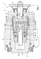
- Fig. 1 is a sectional view of a caliper with adjusting and actuating device shown. This circumvents the problem of excessive component load of the cartridge of the adjusting device described in the prior art, due to the high friction in the sliding bearing, by using an extremely low-friction bearing.
- a motor vehicle disc brake includes, inter alia, a housing 2, a piston 3 which is slidably disposed in a bore 4 for brake actuation.
- the piston 3 can be moved in the case of service braking by means of hydraulic pressurization.
- a shaft 5 is provided, by means of which the piston 3 can be moved via an actuator 10 within the bore 4.
- the shaft 5 engages a shaft end 6, on which an actuating lever 7 is mounted, through an opening of the housing 2.
- the actuator 10 acts with the interposition of a variable-length adjusting device 20 on the piston 3 a.
- the actuating device 10 comprises a ramp arrangement 11, which has a housing-fixed ramp element 12 and a counter-rotatable ramp element 13.
- the ramp element 13 is integrally formed on a disk-shaped end portion 8 of the shaft 5.
- Between the ramp elements 12,13 more rolling elements 14 are arranged so that the ramp assembly 10 causes an axial displacement of the shaft 5 in the direction of actuation with mutual rotation of the ramp elements 12,13.
- variable-length adjusting device 20 which transmits the stroke of the ramp assembly 11 to the piston 3 and automatically compensates for wear of the brake pads and brake disc, not shown.
- This adjusting device 20 includes, inter alia, a spindle 21 having an end portion 22 and a screwed onto the shaft 23 of the spindle 21 nut 24, which bears against the piston 3.
- a calotte arrangement 35 is used, which comprises a calotte shell 36 with a concavely curved surface 38 and a dome pin 37 with a convexly curved surface 39.
- the bearing 35 is realized by the spherical cap 36 is provided on the end portion 22 of the spindle 21, which serves to receive the Kalottenzapfens 37.
- This dome pin 37 is placed on the end face of the end portion 8 of the shaft 5.
- the axial surface 39 of the Kalottenzapfens 37 is spherical and has everywhere a constant rounding radius R_ab.
- the receiving surface 38 of the cup shell 36, in which the dome pin 37 rests with the spherical surface 39, is also provided with a constant fillet radius R_out.
- the rounding radius R_ab of the dome pin 37 is smaller than the fillet radius R_ of the dome shell 36, in particular the rounding radius is 89 percent of the size of the fillet radius, but may also be lower or increase to 95%.
- a spring 26 biases the spindle 21 against the bearing 35 via a spring cup 27.
- the spring cup 27 is supported by means of flared lugs 28 axially and radially in recesses 29 in the bore 4 from.
- a housing-fixed cartridge 31 engages around the end portion 22. Since the cartridge 31 has at least partially, the end portion 22 corresponding star-shaped inner profile, it engages the toothing 30 and forms with the end portion 22 a positive connection in tangential direction. Thus, the spindle 21 is slidable in the direction of actuation, but at the same time against rotation within the cartridge 31 and thus also incorporated in the caliper 1.
- the essential components of the mechanical actuating device 10 and the adjusting device 20 according to the invention are combined to form an assembly.
- the preassembled assembly includes the ramp assembly 11, the shaft 5, the thrust bearing, the spindle 21, the spring 26 and the cartridge 31 and the spring cup 27.
- the ramp assembly 11, the bearing and the spindle 21 are inserted into the cartridge 31, which is then closed with deformed tabs 32 with the rotationally fixed ramp element 12, and so the items are held captive in the cartridge 31.
- the spring cup 27 can be used together with the inner spring 26 on issued tabs 33rd lock with the cartridge 31.
- the resulting pre-assembled assembly unit can be handled separately and digs after insertion into the bore 4 via more flared lugs 28 of the spring cup 27 in recesses 29 in the brake caliper. 1
Abstract
Description
- Die Erfindung betrifft einen Bremssattel einer Scheibenbremse, umfassend ein Gehäuse mit einer Bohrung, in der ein Kolben axial verschiebbar angeordnet ist, und eine Welle zur Betätigung, die drehbar und axial verschiebbar gelagert ist und mit einem Wellenende eine Gehäuseöffnung durchgreift, und zwei gegeneinander verdrehbare Rampenelemente, von denen ein Rampenelement drehfest mit dem Gehäuse und ein Rampenelement drehfest mit der Welle verbunden ist, und eine Nachstellvorrichtung mit einer Spindel, wobei die Nachstellvorrichtung zwischen der Welle und dem Kolben vorhanden ist, und ein zwischen Spindel und Welle wirksames Axiallager.
- Aus der
EP 0 403 635 B1 ist ein solcher kombinierter Bremssattel für eine Kraftfahrzeug-Scheibenbremse bekannt. Der Bremssattel umfasst ein Gehäuse mit einer Bohrung, in der ein Kolben zur Bremsbetätigung verschiebbar angeordnet ist. Für Feststellbremsungen ist im Bremsgehäuse eine Welle drehbar gelagert, wobei die Welle das Bremsgehäuse durchgreift und mit einem Rampenelement einer Rampenanordnung verbunden ist. Ein zweites zugehöriges Rampenelement ist gehäusefest angeordnet. - Aufgrund der Verbindung von Welle und Rampenanordnung, vollführt die Welle bei einer Betätigung der Feststellbremse
- eine Rotation und eine axiale Verschiebung. Die Welle überträgt die axiale Verschiebung auf eine Spindel einer Nachstellvorrichtung, wobei zur Entkopplung der Translation von der Rotation zwischen der Welle und der Spindel ein Axiallager vorgesehen ist. Die axiale Verschiebung wird über die Nachstellvorrichtung auf den Kolben übertragen. Zur Umwandlung der Dreh- in eine Axialbewegung muss die Spindel der Nachstellvorrichtung über eine Patrone der Nachstellvorrichtung im Gehäuse tangential abgestützt werden. Diese Verdrehsicherung ist notwendig, da das Axiallager ein restliches Drehmoment in die Spindel überträgt.
- Dabei ist die Patrone drehfest mit der gehäusefesten Rampenanordnung verbunden und weist drei Längsschlitze auf, in welchen sich die Spindel mittels dreier Vorsprünge tangential abstützt. Hierbei stellt sich der Nachteil ein, dass an den Flanken der Schlitze und an den Vorsprüngen der Spindel erhebliche Flächenpressungen und Spannungsspitzen auftreten, und diese ungleichmäßige Bauteilbelastung zu einem erhöhten Verschleiß führt. Die Längsschlitze bedingen eine niedrige Stabilität der Patrone, wodurch eine dicke Wandstärke der Patrone erforderlich ist.
- Zur Entlastung der Bauteile der Verdrehsicherung ist angeführt, das Axiallager zwischen Welle und Spindel als Wälz- oder Gleitlager auszuführen. Mit der Verwendung eines Wälzlagers wird ein niedriger Drehmomenteintrag in die Verdrehsicherung erreicht. Da Wälzlager kostenintensiv sind, die Bauteilkomplexität erhöhen und die jeweiligen Laufflächen gehärtet sein müssen, bedingt diese Lösung hohe Herstellungskosten, und ist deshalb als nicht praktikabel anzusehen. Dem gegenüber bringt eine Gleitlagerung mit einer axial wirksamen Gleitlagerscheibe einen Kostenvorteil mit sich, verursacht aber aufgrund der höheren Lagerreibung erhöhte Bauteilspannungen in der Nachstellvorrichtung.
- Ausgehend davon ist es eine Aufgabe der Erfindung, einen gattungsgemäßen Bremssattel einer Scheibenbremse anzugeben, wobei die Bauteile auf einer beanpruchungsgerechten Konstruktion beruhen, so dass diese einer gleichmäßigen, niedrigen Belastung ohne schädliche Spannungsspitzen ausgesetzt sind.
- Erfindungsgemäß wird die Aufgabe dadurch gelöst, dass als Axiallager eine Kalottenanordnung vorgesehen ist, welche eine Kalottenschale mit einer konkav gekrümmten Oberfläche und einen Kalottenzapfen mit einer konvex gekrümmten Oberfläche umfasst. Dieses Lagerungskonzept birgt den Vorteil, dass die Kontaktfläche im Lager sehr klein ist, wodurch die Reibung wesentlich reduziert wird. Dadurch verringert sich das in die Nachstellvorrichtung übertragene Moment, was zu einer Reduzierung der auftretenden Kräfte in Spindel und Patrone führt und keine übermäßigen Flächenpressungen und Spannungsspitzen darin auftreten. Eine günstige Ausprägung der Oberflächen beinhaltet, dass diese sphärisch sind.
- Besonders vorteilhaft zeigt sich dieses Lösungskonzept, wenn der Oberfläche der Kalottenschale mindestens ein Ausrundungsradius, und der Oberfläche des Kalottenzapfens mindestens ein Abrundungsradius zuordenbar ist, wobei der Ausrundungsradius größer als der Abrundungsradius ist.
- In zahlreichen Versuchen hat sich ergeben, dass die gewünschte Funktion des Lagers am besten erfüllt wird, wenn der Abrundungsradius des Kalottenzapfens maximal 95 Prozent der Größe des Ausrundungsradius der Kalottenschale beträgt. Je geringer dieser Wert ist, desto niedriger ist der Übertragungswiderstand, jedoch treten dann in der Kontaktfläche von Kalottenzapfen und Kalottenschale übermäßig hohe Flächenpressungen auf. Wird dieser Wert überschritten, so nimmt systematisch die Lagerreibung weiter zu, wodurch die Nachstellung einen schlechteren Übertragungswiderstand bekommt
- Indem die Kalottenschale und ein Endabschnitt der Spindel einstückig ausgeführt sind, und die Kalottenschale auf einer axialen Stirnseite des Endabschnitts der Spindel vorgesehen ist, und der Kalottenzapfen an einen Endabschnitt der Welle einteilig angeformt ist verringern sich die Herstellungs- und Montagekosten erheblich, da die Fertigung der Bauteile vereinfacht und deren Anzahl reduziert wird.
- Gleiches gilt für die Ausführung, dass die Kalottenschale und ein Endabschnitt der Welle einstückig ausgeführt sind, und die Kalottenschale auf einer axialen Stirnseite des Endabschnitts der Welle vorgesehen ist, und dass der Kalottenzapfen an einen Endabschnitt der Spindel einteilig angeformt ist.
- Durch die erfindungsgemäße Konstellation der einzelnen Bauteile im Bremssattel vereinfacht sich die Montage erheblich. Diese beinhaltet, dass ein Federtopf über ausgestellte Laschen an der Patrone fixiert ist, und die Patrone mittels umgeformter Laschen mit dem drehfesten Rampenelement verbunden ist, so dass Patrone, Federtopf und Rampenelement eine Montageeinheit bilden.
- Besonders vorteilhaft wirkt sich obige Konstellation der Einzelteile als Montageeinheit aus, wenn der Federtopf ausgestellte Laschen aufweist, wodurch die Montageeinheit in Ausnehmungen der Bohrung fixierbar ist.
- Weitere sinnvolle Detailmerkmale der Erfindung sind dem Ausführungsbeispiel in der Figur zu entnehmen, die im Folgenden näher erläutert wird.
- In der Zeichnung zeigt
- Fig. 1
- eine Schnittansicht eines Bremssattels mit Nachstell- und Betätigungsvorrichtung gemäß einer Ausführungsform.
- In
Fig. 1 ist eine Schnittansicht eines Bremssattels mit Nachstell- und Betätigungsvorrichtung dargestellt. Darin wird die im Stand der Technik beschriebene Problematik der übermäßigen Bauteilbelastung der Patrone der Nachstellvorrichtung, bedingt durch die hohe Reibung im Gleitlager, umgangen, indem eine extrem reibungsarme Lagerung zur Anwendung kommt. - Der in
Fig. 1 gezeigte Bremssattel 1 einer Kraftfahrzeug-Scheibenbremse umfasst unter anderem ein Gehäuse 2, einen Kolben 3, der zur Bremsbetätigung in einer Bohrung 4 verschiebbar angeordnet ist. Dabei kann der Kolben 3 im Falle einer Betriebsbremsung mittels hydraulischer Druckbeaufschlagung verschoben werden. Zur Umsetzung einer Feststellbremsung ist eine Welle 5 vorgesehen, mittels derer der Kolben 3 über eine Betätigungsvorrichtung 10 innerhalb der Bohrung 4 verschoben werden kann. Die Welle 5 greift mit
einem Wellenende 6, an welchem ein Betätigungshebel 7 angebracht ist, durch eine Öffnung des Gehäuses 2. Die Betätigungsvorrichtung 10 wirkt unter Zwischenschaltung einer längenveränderlichen Nachstellvorrichtung 20 auf den Kolben 3 ein. - Die Betätigungsvorrichtung 10 umfasst eine Rampenanordnung 11, die ein gehäusefestes Rampenelement 12 sowie ein demgegenüber drehbares Rampenelement 13 aufweist. Dabei ist das Rampenelement 13 einstückig auf einem scheibenförmigen Endabschnitt 8 der Welle 5 ausgebildet. Zwischen den Rampenelementen 12,13 sind mehrere Wälzkörper 14 angeordnet, so dass die Rampenanordnung 10 bei gegenseitiger Verdrehung der Rampenelemente 12,13 eine axiale Verschiebung der Welle 5 in Betätigungsrichtung bewirkt.
- Zwischen dem Endabschnitt 8 der Welle 5 und dem Kolben 3 ist eine längenveränderliche Nachstellvorrichtung 20 vorhanden, die den Hub der Rampenanordnung 11 auf den Kolben 3 überträgt und einen Verschleiß der nicht dargestellten Bremsbeläge und Bremsscheibe automatisch ausgleicht. Diese Nachstellvorrichtung 20 umfasst unter anderem eine Spindel 21 mit einem Endabschnitt 22 und eine auf den Schaft 23 der Spindel 21 aufgeschraubte Mutter 24, die am Kolben 3 anliegt.
- Es wird eine Kalottenanordnung 35 verwendet, welche eine Kalottenschale 36 mit einer konkav gekrümmten Oberfläche 38 und einen Kalottenzapfen 37 mit einer konvex gekrümmten Oberfläche 39 umfasst.
- Das Lager 35 ist derart realisiert, indem auf dem Endabschnitt 22 der Spindel 21 die Kalottenschale 36 vorgesehen ist, die zur Aufnahme des Kalottenzapfens 37 dient. Dieser Kalottenzapfen 37 ist auf der Stirnseite des Endabschnitts 8 der Welle 5 platziert. Dabei ist die axiale Oberfläche 39 des Kalottenzapfens 37 sphärisch ausgeführt und weist überall einen konstanten Abrundungsradius R_ab auf. Korrelierend dazu ist die aufnehmende Oberfläche 38 der Kalottenschale 36, in welcher der Kalottenzapfen 37 mit der sphärischen Oberfläche 39 aufliegt, auch mit einem konstantem Ausrundungsradius R_aus versehen. Damit der Kalottenzapfen 37 in die Kalottenschale 36 greifen kann, ist der Abrundungsradius R_ab des Kalottenzapfens 37 kleiner als der Ausrundungsradius R_aus der Kalottenschale 36, insbesondere beträgt der Abrundungsradius 89 Prozent der Größe des Ausrundungsradius, kann aber auch darunter liegen oder auf 95 % zunehmen. Je größer der Unterschied zwischen den Radien ist, desto geringer fällt die Reibung zwischen Zapfen 37 und Kalotte 36 aus, jedoch steigt damit die Flächenpressung im Kontaktpunkt.
- Eine Feder 26 spannt über einen Federtopf 27 die Spindel 21 gegen das Lager 35 vor. Der Federtopf 27 stützt sich mittels ausgestellter Laschen 28 axial und radial in Ausnehmungen 29 in der Bohrung 4 ab.
- Auf dem Umfang eines Endabschnitts 22 der Spindel 21 sind mehrere regelmäßige Zähne der Verzahnung 30 angebracht, so dass der Endabschnitt 22 einen sternförmigen Querschnitt aufweist. Um die Spindel 21 gegen Verdrehen zu sichern, umgreift eine gehäusefeste Patrone 31 den Endabschnitt 22. Da die Patrone 31 zumindest teilweise ein, dem Endabschnitt 22 entsprechendes, sternförmiges Innenprofil hat, greift sie in die Verzahnung 30 und bildet mit dem Endabschnitt 22 eine formschlüssige Verbindung in tangentialer Richtung. Damit ist die Spindel 21 in Betätigungsrichtung verschiebbar, aber gleichzeitig verdrehsicher innerhalb der Patrone 31 und damit auch im Bremssattel 1 aufgenommen.
- Zur Bildung einer einfach handhabbaren Montageeinheit sind die wesentlichen Komponenten der mechanischen Betätigungsvorrichtung 10 und der Nachstellvorrichtung 20 erfindungsgemäß zu einer Baugruppe zusammengefügt. Dies wird durch die Patrone 31 in Verbindung mit dem Federtopf 27 und dem Rampenelement 12 erreicht, wobei diese die einzelnen Komponenten der Baugruppe umschließen. Die vormontierbare Baugruppe enthält die Rampenanordnung 11, die Welle 5, das Axiallager, die Spindel 21, die Feder 26 und die Patrone 31 sowie den Federtopf 27. Dabei werden zunächst die Rampenanordnung 11, das Lager sowie die Spindel 21 in die Patrone 31 eingesetzt, die anschließend mit umgeformten Laschen 32 mit dem drehfesten Rampenelement 12 verschlossen wird, und so die Einzelteile verliersicher in der Patrone 31 gehalten werden. Danach lässt sich der Federtopf 27 zusammen mit der innen liegenden Feder 26 an ausgestellten Laschen 33 mit der Patrone 31 verrasten. Die dadurch entstandene vormontierte Montageeinheit lässt sich separat handhaben und verkrallt sich nach dem Einführen in die Bohrung 4 über weitere ausgestellte Laschen 28 des Federtopfes 27 in Ausnehmungen 29 im Bremssattel 1.
- Der funktionelle Ablauf der Feststellbremsbetätigung im Bremssattel 1 aus
Fig. 1 wird im Folgenden dargelegt. Bei Betätigung der Feststellbremse wird über den Betätigungs-hebel 7 die Welle 5 und der Endabschnitt 8 gedreht und die Rampenanordnung 11 verdreht. Dadurch bewirken die beiden Rampenelementen 12 und 13 eine axiale Verschiebung der Welle 5 und des Endabschnitts 8. Diese axiale Verschiebung wird mittels des axialen Lagers 35 auf den Endabschnitt 22 bzw. auf die Spindel 21 übertragen. Da die Spindel 21 über die Verzahnung 30 des Endabschnitts 22 drehfest in der Patrone 31 geführt ist, vollzieht die Spindel 21 ausschließlich eine axiale Verschiebung ohne Rotation. Über die auf dem Schaft 23 aufgeschraubte Mutter 24 wird so der Kolben 3 bewegt und blockiert die nicht dargestellte Bremsscheibe. -
- 1
- Bremssattel
- 2
- Gehäuse
- 3
- Kolben
- 4
- Bohrung
- 5
- Welle
- 6
- Wellenende
- 7
- Betätigungshebel
- 8
- Endabschnitt
- 9
- Längsachse
- 10
- Betätigungsvorrichtung
- 11
- Rampenanordnung
- 12
- gehäusefestes Rampenelement
- 13
- drehbares Rampenelement
- 14
- Wälzkörper
- 20
- Nachstellvorrichtung
- 21
- Spindel
- 22
- Endabschnitt
- 23
- Schaft
- 24
- Mutter
- 25
- 26
- Feder
- 27
- Federtopf
- 28
- ausgestellte Lasche
- 29
- Ausnehmung
- 30
- Verzahnung
- 31
- Patrone
- 32
- Lasche
- 33
- ausgestellte Lasche
- 34
- 35
- Kalottenanordnung
- 36
- Kalottenschale
- 37
- Kalottenzapfen
- 38
- konkave Oberfläche
- 39
- konvexe Oberfläche
- R_ab
- Abrundungsradius
- R_aus
- Ausrundungsradius
Claims (8)
- Bremssattel einer Scheibenbremse, umfassend- ein Gehäuse mit einer Bohrung, in der ein Kolben axial verschiebbar angeordnet ist,- und eine Welle zur Betätigung, die drehbar und axial verschiebbar gelagert ist und mit einem Wellenende eine Gehäuseöffnung durchgreift,- und zwei gegeneinander verdrehbare Rampenelemente, von denen ein Rampenelement drehfest mit dem Gehäuse und ein Rampenelement drehfest mit der Welle verbunden ist,- und eine Nachstellvorrichtung mit einer Spindel, wobei die Nachstellvorrichtung zwischen der Welle und dem Kolben vorhanden ist,- und ein zwischen Spindel und Welle wirksames Axiallager, dadurch gekennzeichnet, dass als Axiallager eine Kalottenanordnung (35) vorgesehen ist, welche eine Kalottenschale (36) mit einer konkav gekrümmten Oberfläche (38) und einen Kalottenzapfen (37) mit einer konvex gekrümmten Oberfläche (39) umfasst.
- Bremssattel nach Anspruch 1, dadurch gekennzeichnet, dass die Oberfläche (39) des Kalottenzapfens (37) und die Oberfläche (38) der Kalottenschale (36) sphärisch sind.
- Bremssattel nach Anspruch 1 oder 2, dadurch gekennzeichnet, dass der Oberfläche (38) mindestens ein Ausrundungsradius (R_aus), und der Oberfläche (39) mindestens ein Abrundungsradius (R_ab) zuordenbar ist, wobei der Ausrundungsradius (R_aus) größer als der Abrundungsradius (R_ab) ist.
- Bremssattel nach Anspruch 3, dadurch gekennzeichnet, dass der Abrundungsradius (R_ab) maximal 95 Prozent der Größe des Ausrundungsradius (R_aus) beträgt.
- Bremssattel nach Anspruch 1, dadurch gekennzeichnet, dass die Kalottenschale (36) und ein Endabschnitt (22) der Spindel (21) einstückig ausgeführt sind, und die Kalottenschale (36) auf einer axialen Stirnseite des Endabschnitts (22) der Spindel (21) vorgesehen ist, und dass der Kalottenzapfen (37) an einen Endabschnitt (8) der Welle (5) einteilig angeformt ist.
- Bremssattel nach Anspruch 1, dadurch gekennzeichnet, dass die Kalottenschale (36) und ein Endabschnitt (8) der Welle (5) einstückig ausgeführt sind, und die Kalottenschale (36) auf einer axialen Stirnseite des Endabschnitts (8) der Welle (5) vorgesehen ist, und dass der Kalottenzapfen (37) an einen Endabschnitt (22) der Spindel (21) einteilig angeformt ist.
- Bremssattel nach einem oder mehreren vorangestellten Ansprüchen, dadurch gekennzeichnet, dass ein Federtopf (27) über ausgestellte Laschen (33) an der Patrone (31) fixiert ist, und die Patrone (31) mittels umgeformter Laschen (32) mit dem drehfesten Rampenelement (12) verbunden ist, so dass Patrone (31), Federtopf (27) und Rampenelement (12) eine Montageeinheit bilden.
- Bremssattel nach Anspruch 1, dadurch gekennzeichnet, dass der Federtopf (27) ausgestellte Laschen (28) aufweist, wodurch die Montageeinheit in Ausnehmungen (29) der Bohrung (4) fixierbar ist.
Applications Claiming Priority (3)
| Application Number | Priority Date | Filing Date | Title |
|---|---|---|---|
| DE102004057276 | 2004-11-26 | ||
| DE102005056166A DE102005056166A1 (de) | 2004-11-26 | 2005-11-23 | Bremssattel einer Scheibenbremse |
| EP05811128A EP1819935B1 (de) | 2004-11-26 | 2005-11-25 | Bremssattel einer scheibenbremse |
Related Parent Applications (1)
| Application Number | Title | Priority Date | Filing Date |
|---|---|---|---|
| EP05811128A Division EP1819935B1 (de) | 2004-11-26 | 2005-11-25 | Bremssattel einer scheibenbremse |
Publications (2)
| Publication Number | Publication Date |
|---|---|
| EP2065611A1 true EP2065611A1 (de) | 2009-06-03 |
| EP2065611B1 EP2065611B1 (de) | 2010-02-03 |
Family
ID=36441886
Family Applications (2)
| Application Number | Title | Priority Date | Filing Date |
|---|---|---|---|
| EP05811128A Expired - Fee Related EP1819935B1 (de) | 2004-11-26 | 2005-11-25 | Bremssattel einer scheibenbremse |
| EP09154173A Not-in-force EP2065611B1 (de) | 2004-11-26 | 2005-11-25 | Bremssattel einer Scheibenbremse |
Family Applications Before (1)
| Application Number | Title | Priority Date | Filing Date |
|---|---|---|---|
| EP05811128A Expired - Fee Related EP1819935B1 (de) | 2004-11-26 | 2005-11-25 | Bremssattel einer scheibenbremse |
Country Status (7)
| Country | Link |
|---|---|
| US (1) | US7523815B2 (de) |
| EP (2) | EP1819935B1 (de) |
| JP (1) | JP5122972B2 (de) |
| KR (1) | KR101249622B1 (de) |
| BR (1) | BRPI0517873A (de) |
| DE (3) | DE102005056166A1 (de) |
| WO (1) | WO2006056598A2 (de) |
Families Citing this family (15)
| Publication number | Priority date | Publication date | Assignee | Title |
|---|---|---|---|---|
| ITMI20071599A1 (it) * | 2007-08-02 | 2009-02-03 | Freni Brembo Spa | Attuatore per freno di stazionamento |
| KR100891485B1 (ko) * | 2007-10-29 | 2009-04-02 | 주식회사 만도 | 디스크 브레이크의 주차브레이크 장치 |
| CN101852257B (zh) * | 2009-03-30 | 2014-02-19 | 京西重工(上海)有限公司 | 带驻车制动的盘式制动钳 |
| DE102009034503A1 (de) | 2009-06-30 | 2011-01-05 | Continental Teves Ag & Co. Ohg | Bremssattel einer Scheibenbremse |
| DE102009036884A1 (de) * | 2009-08-10 | 2011-05-19 | Schaeffler Technologies Gmbh & Co. Kg | Kugelgewindetrieb, mit axial abgestützter Gewindespindel |
| JP5551931B2 (ja) * | 2009-12-25 | 2014-07-16 | 日立オートモティブシステムズ株式会社 | ディスクブレーキ |
| JP5148668B2 (ja) | 2010-01-26 | 2013-02-20 | 曙ブレーキ工業株式会社 | パーキング機構付ディスクブレーキ装置 |
| KR20110124599A (ko) | 2010-05-11 | 2011-11-17 | 주식회사 만도 | 주차 브레이크 |
| KR101618868B1 (ko) | 2010-10-19 | 2016-05-09 | 현대모비스 주식회사 | 차량용 캘리퍼장치 |
| KR101351346B1 (ko) * | 2012-07-20 | 2014-01-15 | 주식회사 만도 | 디스크 브레이크 |
| KR101761593B1 (ko) * | 2013-08-26 | 2017-07-27 | 주식회사 만도 | 디스크 브레이크 |
| KR101853779B1 (ko) * | 2014-04-28 | 2018-05-02 | 주식회사 만도 | 디스크 브레이크 |
| US9964165B2 (en) * | 2015-12-04 | 2018-05-08 | Akebono Brake Industry Co., Ltd | Brake piston |
| DE102017125867B4 (de) * | 2017-11-06 | 2022-05-25 | Knorr-Bremse Systeme für Nutzfahrzeuge GmbH | Nachstelleinrichtung einer Scheibenbremse |
| IT202100012368A1 (it) | 2021-05-13 | 2022-11-13 | Brembo Spa | Pinza freno di un disco per freno a disco |
Citations (3)
| Publication number | Priority date | Publication date | Assignee | Title |
|---|---|---|---|---|
| GB2155126A (en) * | 1984-02-13 | 1985-09-18 | Kelsey Hayes Co | Disc brake adjustors |
| EP0403635B1 (de) | 1989-01-11 | 1992-08-26 | Lucas Industries Public Limited Company | Betätigungsvorrichtung mit selbsttätiger nachstellung für eine fahrzeugbremse |
| US5820271A (en) * | 1997-01-29 | 1998-10-13 | Hackett, Jr.; William F. | Thrust bearing assembly |
Family Cites Families (21)
| Publication number | Priority date | Publication date | Assignee | Title |
|---|---|---|---|---|
| FR2041002A1 (de) * | 1969-04-22 | 1971-01-29 | Dba | |
| US4325382A (en) * | 1980-05-15 | 1982-04-20 | Memorial Hospital For Cancer And Allied Diseases | Process and apparatus for the real time adaptive filtering of catheter pressure measurements |
| JPH0452500Y2 (de) * | 1987-08-10 | 1992-12-10 | ||
| DE9000257U1 (de) * | 1990-01-11 | 1991-05-16 | Lucas Industries P.L.C., Birmingham, West Midlands, Gb | |
| JP2820760B2 (ja) * | 1990-02-23 | 1998-11-05 | 株式会社松井製作所 | 異形チューブの製造方法 |
| JP2652592B2 (ja) * | 1991-05-17 | 1997-09-10 | 日本スカイロボット株式会社 | 伸縮柱等の進退機構 |
| FR2701526B1 (fr) * | 1993-02-16 | 1995-04-28 | Alliedsignal Europ Services | Dispositif à plateaux à billes et à cage de centrage. |
| DE9407623U1 (de) * | 1994-05-06 | 1995-09-07 | Lucas Ind Plc | Betätigungsvorrichtung für eine Fahrzeugbremse, insbesondere Scheibenbremse |
| US6911887B1 (en) | 1994-09-12 | 2005-06-28 | Matsushita Electric Industrial Co., Ltd. | Inductor and method for producing the same |
| FR2741412B1 (fr) * | 1995-11-17 | 1998-02-13 | Alliedsignal Europ Services | Moteur de frein a tolerance augmentee |
| JPH1124004A (ja) * | 1997-06-27 | 1999-01-29 | Tetsuo Yoshioka | 眼鏡部品締結用ねじ装置 |
| DE19750273A1 (de) * | 1997-11-13 | 1999-05-20 | Bosch Gmbh Robert | Elektromechanische Bremse für Kraftfahrzeuge |
| DE19858651C1 (de) | 1998-12-18 | 2000-08-31 | Lucas Ind Plc | Betätigungsvorrichtung mit selbsttätiger Nachstellung für eine hydraulische Fahrzeugscheibenbremse |
| US6651784B1 (en) * | 1999-09-07 | 2003-11-25 | Akebono Corporation North America | Automatically-adjusting, hand-brake actuator and housing of light weight material |
| FR2800825B1 (fr) * | 1999-11-08 | 2002-01-11 | Bosch Gmbh Robert | Rampe a billes et cylindre de freins comportant une telle rampe |
| FR2817218B1 (fr) * | 2000-11-28 | 2003-01-10 | Bosch Gmbh Robert | Cylindre de frein a disque avec mecanisme de frein de parc |
| FR2829543B1 (fr) * | 2001-09-10 | 2003-12-19 | Bosch Gmbh Robert | Cylindre de frein a actionnement mecanique et hydraulique pour vehicule automobile comportant une neutralisation de reglage annulaire et frein a disque comporatnt un tel cylindre |
| JP3929757B2 (ja) * | 2001-11-16 | 2007-06-13 | 株式会社日立製作所 | ディスクブレーキ |
| US6659236B1 (en) * | 2002-06-28 | 2003-12-09 | Robert Bosch Corporation | Parking brake |
| JP4194870B2 (ja) * | 2003-01-31 | 2008-12-10 | 株式会社日立製作所 | ディスクブレーキ |
| US7331432B2 (en) * | 2005-08-26 | 2008-02-19 | Nissin Kogyo Co., Ltd. | Disk brake apparatus |
-
2005
- 2005-11-23 DE DE102005056166A patent/DE102005056166A1/de not_active Withdrawn
- 2005-11-25 DE DE502005007107T patent/DE502005007107D1/de active Active
- 2005-11-25 WO PCT/EP2005/056221 patent/WO2006056598A2/de active Application Filing
- 2005-11-25 BR BRPI0517873-8A patent/BRPI0517873A/pt not_active Application Discontinuation
- 2005-11-25 EP EP05811128A patent/EP1819935B1/de not_active Expired - Fee Related
- 2005-11-25 US US11/791,507 patent/US7523815B2/en not_active Expired - Fee Related
- 2005-11-25 KR KR1020077011912A patent/KR101249622B1/ko active IP Right Grant
- 2005-11-25 JP JP2007541987A patent/JP5122972B2/ja not_active Expired - Fee Related
- 2005-11-25 DE DE502005008984T patent/DE502005008984D1/de not_active Withdrawn - After Issue
- 2005-11-25 EP EP09154173A patent/EP2065611B1/de not_active Not-in-force
Patent Citations (3)
| Publication number | Priority date | Publication date | Assignee | Title |
|---|---|---|---|---|
| GB2155126A (en) * | 1984-02-13 | 1985-09-18 | Kelsey Hayes Co | Disc brake adjustors |
| EP0403635B1 (de) | 1989-01-11 | 1992-08-26 | Lucas Industries Public Limited Company | Betätigungsvorrichtung mit selbsttätiger nachstellung für eine fahrzeugbremse |
| US5820271A (en) * | 1997-01-29 | 1998-10-13 | Hackett, Jr.; William F. | Thrust bearing assembly |
Also Published As
| Publication number | Publication date |
|---|---|
| US20080135354A1 (en) | 2008-06-12 |
| EP2065611B1 (de) | 2010-02-03 |
| WO2006056598A2 (de) | 2006-06-01 |
| EP1819935B1 (de) | 2009-04-15 |
| DE502005007107D1 (de) | 2009-05-28 |
| BRPI0517873A (pt) | 2008-10-21 |
| JP2008522106A (ja) | 2008-06-26 |
| DE502005008984D1 (de) | 2010-03-25 |
| DE102005056166A1 (de) | 2006-06-08 |
| KR101249622B1 (ko) | 2013-04-01 |
| EP1819935A2 (de) | 2007-08-22 |
| WO2006056598A3 (de) | 2006-08-03 |
| JP5122972B2 (ja) | 2013-01-16 |
| KR20070085463A (ko) | 2007-08-27 |
| US7523815B2 (en) | 2009-04-28 |
Similar Documents
| Publication | Publication Date | Title |
|---|---|---|
| EP2065611B1 (de) | Bremssattel einer Scheibenbremse | |
| EP2207982B1 (de) | Kombinierte fahrzeugbremse mit elektromechanisch betätigbarer feststellbremse | |
| EP2317178B1 (de) | Kugelgewindetrieb für eine Feststellbremse eines Kraftfahrzeuges | |
| EP0739459B1 (de) | Zuspannvorrichtung einer scheibenbremse, insbesondere für schwere nutzfahrzeuge | |
| EP0403635B1 (de) | Betätigungsvorrichtung mit selbsttätiger nachstellung für eine fahrzeugbremse | |
| EP2414698B1 (de) | Elektromechanische fahrzeugbremse | |
| EP0544851B1 (de) | Druckgesteuerte nachstellvorrichtung für eine fahrzeugbremse | |
| DE102008062180B4 (de) | Kombinierte Fahrzeugbremse mit elektromechanisch betätigbarer Feststellbremse | |
| DE2408706A1 (de) | Betaetigungsvorrichtung fuer eine fahrzeug-bremsanlage mit selbsttaetiger spielnachstellvorrichtung | |
| DE2420985C2 (de) | Scheibenbremse, insbesondere für Kraftfahrzeuge | |
| DE2817389A1 (de) | Mechanische bremsbetaetigungsvorrichtung | |
| EP2016303B1 (de) | Kombinierter bremssattel | |
| DE102012208294A1 (de) | Getriebemotorantrieb mit einer Kupplung, insbesondere für eine kombinierte Kraftfahrzeugbremse | |
| DE3336119C2 (de) | ||
| EP1714050B1 (de) | Nachstellvorrichtung für eine scheibenbremse, insbesondere eine pneumatisch betätigten scheibenbremse | |
| DE102017119079A1 (de) | Doppelschlingfeder, Rotationseinrichtung und zu aktuierendes System | |
| WO2013149777A1 (de) | Kombiniert betätigbarer bremssattel | |
| DE2218929C3 (de) | Selbsttätige Nachstellvorrichtung, insbesondere für Fahrzeugbremsen | |
| DE102016214711A1 (de) | Doppelschlingfeder, Rotationseinrichtung und zu aktuierendes System | |
| DE3505774C2 (de) | ||
| DE102017206865A1 (de) | Scheibenbremse für einen Rotor einer Windkraftanlage | |
| DE2629211B2 (de) | Selbstverstärkend wirkende Vollscheibenbremse, insbesondere der naßlaufenden Bauart | |
| DE102005043855B4 (de) | Hydraulische Maschine | |
| EP3510300B1 (de) | Nachsteller für ein bremssystem | |
| DE4100903C2 (de) |
Legal Events
| Date | Code | Title | Description |
|---|---|---|---|
| PUAI | Public reference made under article 153(3) epc to a published international application that has entered the european phase |
Free format text: ORIGINAL CODE: 0009012 |
|
| 17P | Request for examination filed |
Effective date: 20090303 |
|
| AC | Divisional application: reference to earlier application |
Ref document number: 1819935 Country of ref document: EP Kind code of ref document: P |
|
| AK | Designated contracting states |
Kind code of ref document: A1 Designated state(s): DE FR IT |
|
| GRAP | Despatch of communication of intention to grant a patent |
Free format text: ORIGINAL CODE: EPIDOSNIGR1 |
|
| GRAS | Grant fee paid |
Free format text: ORIGINAL CODE: EPIDOSNIGR3 |
|
| GRAA | (expected) grant |
Free format text: ORIGINAL CODE: 0009210 |
|
| AC | Divisional application: reference to earlier application |
Ref document number: 1819935 Country of ref document: EP Kind code of ref document: P |
|
| AK | Designated contracting states |
Kind code of ref document: B1 Designated state(s): DE FR IT |
|
| AKX | Designation fees paid |
Designated state(s): DE FR IT |
|
| REF | Corresponds to: |
Ref document number: 502005008984 Country of ref document: DE Date of ref document: 20100325 Kind code of ref document: P |
|
| PLBE | No opposition filed within time limit |
Free format text: ORIGINAL CODE: 0009261 |
|
| STAA | Information on the status of an ep patent application or granted ep patent |
Free format text: STATUS: NO OPPOSITION FILED WITHIN TIME LIMIT |
|
| 26N | No opposition filed |
Effective date: 20101104 |
|
| PGFP | Annual fee paid to national office [announced via postgrant information from national office to epo] |
Ref country code: FR Payment date: 20101209 Year of fee payment: 6 |
|
| PGFP | Annual fee paid to national office [announced via postgrant information from national office to epo] |
Ref country code: IT Payment date: 20101119 Year of fee payment: 6 |
|
| PG25 | Lapsed in a contracting state [announced via postgrant information from national office to epo] |
Ref country code: DE Free format text: LAPSE BECAUSE OF THE APPLICANT RENOUNCES Effective date: 20101218 |
|
| REG | Reference to a national code |
Ref country code: FR Ref legal event code: ST Effective date: 20120731 |
|
| PG25 | Lapsed in a contracting state [announced via postgrant information from national office to epo] |
Ref country code: IT Free format text: LAPSE BECAUSE OF NON-PAYMENT OF DUE FEES Effective date: 20111125 |
|
| PG25 | Lapsed in a contracting state [announced via postgrant information from national office to epo] |
Ref country code: FR Free format text: LAPSE BECAUSE OF NON-PAYMENT OF DUE FEES Effective date: 20111130 |