EP2065603A1 - Wellenvorrichtung mit Rollenlager - Google Patents
Wellenvorrichtung mit Rollenlager Download PDFInfo
- Publication number
- EP2065603A1 EP2065603A1 EP08020443A EP08020443A EP2065603A1 EP 2065603 A1 EP2065603 A1 EP 2065603A1 EP 08020443 A EP08020443 A EP 08020443A EP 08020443 A EP08020443 A EP 08020443A EP 2065603 A1 EP2065603 A1 EP 2065603A1
- Authority
- EP
- European Patent Office
- Prior art keywords
- shaft
- roller bearing
- camshaft
- fitted
- axial direction
- Prior art date
- Legal status (The legal status is an assumption and is not a legal conclusion. Google has not performed a legal analysis and makes no representation as to the accuracy of the status listed.)
- Granted
Links
Images


Classifications
-
- F—MECHANICAL ENGINEERING; LIGHTING; HEATING; WEAPONS; BLASTING
- F01—MACHINES OR ENGINES IN GENERAL; ENGINE PLANTS IN GENERAL; STEAM ENGINES
- F01L—CYCLICALLY OPERATING VALVES FOR MACHINES OR ENGINES
- F01L1/00—Valve-gear or valve arrangements, e.g. lift-valve gear
- F01L1/02—Valve drive
- F01L1/04—Valve drive by means of cams, camshafts, cam discs, eccentrics or the like
- F01L1/047—Camshafts
-
- F—MECHANICAL ENGINEERING; LIGHTING; HEATING; WEAPONS; BLASTING
- F16—ENGINEERING ELEMENTS AND UNITS; GENERAL MEASURES FOR PRODUCING AND MAINTAINING EFFECTIVE FUNCTIONING OF MACHINES OR INSTALLATIONS; THERMAL INSULATION IN GENERAL
- F16C—SHAFTS; FLEXIBLE SHAFTS; ELEMENTS OR CRANKSHAFT MECHANISMS; ROTARY BODIES OTHER THAN GEARING ELEMENTS; BEARINGS
- F16C19/00—Bearings with rolling contact, for exclusively rotary movement
- F16C19/22—Bearings with rolling contact, for exclusively rotary movement with bearing rollers essentially of the same size in one or more circular rows, e.g. needle bearings
- F16C19/44—Needle bearings
- F16C19/46—Needle bearings with one row or needles
- F16C19/466—Needle bearings with one row or needles comprising needle rollers and an outer ring, i.e. subunit without inner ring
-
- F—MECHANICAL ENGINEERING; LIGHTING; HEATING; WEAPONS; BLASTING
- F16—ENGINEERING ELEMENTS AND UNITS; GENERAL MEASURES FOR PRODUCING AND MAINTAINING EFFECTIVE FUNCTIONING OF MACHINES OR INSTALLATIONS; THERMAL INSULATION IN GENERAL
- F16C—SHAFTS; FLEXIBLE SHAFTS; ELEMENTS OR CRANKSHAFT MECHANISMS; ROTARY BODIES OTHER THAN GEARING ELEMENTS; BEARINGS
- F16C23/00—Bearings for exclusively rotary movement adjustable for aligning or positioning
- F16C23/06—Ball or roller bearings
- F16C23/08—Ball or roller bearings self-adjusting
-
- F—MECHANICAL ENGINEERING; LIGHTING; HEATING; WEAPONS; BLASTING
- F16—ENGINEERING ELEMENTS AND UNITS; GENERAL MEASURES FOR PRODUCING AND MAINTAINING EFFECTIVE FUNCTIONING OF MACHINES OR INSTALLATIONS; THERMAL INSULATION IN GENERAL
- F16C—SHAFTS; FLEXIBLE SHAFTS; ELEMENTS OR CRANKSHAFT MECHANISMS; ROTARY BODIES OTHER THAN GEARING ELEMENTS; BEARINGS
- F16C35/00—Rigid support of bearing units; Housings, e.g. caps, covers
- F16C35/04—Rigid support of bearing units; Housings, e.g. caps, covers in the case of ball or roller bearings
- F16C35/06—Mounting or dismounting of ball or roller bearings; Fixing them onto shaft or in housing
- F16C35/067—Fixing them in a housing
-
- F—MECHANICAL ENGINEERING; LIGHTING; HEATING; WEAPONS; BLASTING
- F01—MACHINES OR ENGINES IN GENERAL; ENGINE PLANTS IN GENERAL; STEAM ENGINES
- F01L—CYCLICALLY OPERATING VALVES FOR MACHINES OR ENGINES
- F01L1/00—Valve-gear or valve arrangements, e.g. lift-valve gear
- F01L1/02—Valve drive
- F01L1/04—Valve drive by means of cams, camshafts, cam discs, eccentrics or the like
- F01L1/047—Camshafts
- F01L2001/0476—Camshaft bearings
-
- F—MECHANICAL ENGINEERING; LIGHTING; HEATING; WEAPONS; BLASTING
- F16—ENGINEERING ELEMENTS AND UNITS; GENERAL MEASURES FOR PRODUCING AND MAINTAINING EFFECTIVE FUNCTIONING OF MACHINES OR INSTALLATIONS; THERMAL INSULATION IN GENERAL
- F16C—SHAFTS; FLEXIBLE SHAFTS; ELEMENTS OR CRANKSHAFT MECHANISMS; ROTARY BODIES OTHER THAN GEARING ELEMENTS; BEARINGS
- F16C2226/00—Joining parts; Fastening; Assembling or mounting parts
- F16C2226/50—Positive connections
-
- F—MECHANICAL ENGINEERING; LIGHTING; HEATING; WEAPONS; BLASTING
- F16—ENGINEERING ELEMENTS AND UNITS; GENERAL MEASURES FOR PRODUCING AND MAINTAINING EFFECTIVE FUNCTIONING OF MACHINES OR INSTALLATIONS; THERMAL INSULATION IN GENERAL
- F16C—SHAFTS; FLEXIBLE SHAFTS; ELEMENTS OR CRANKSHAFT MECHANISMS; ROTARY BODIES OTHER THAN GEARING ELEMENTS; BEARINGS
- F16C2360/00—Engines or pumps
- F16C2360/18—Camshafts
-
- Y—GENERAL TAGGING OF NEW TECHNOLOGICAL DEVELOPMENTS; GENERAL TAGGING OF CROSS-SECTIONAL TECHNOLOGIES SPANNING OVER SEVERAL SECTIONS OF THE IPC; TECHNICAL SUBJECTS COVERED BY FORMER USPC CROSS-REFERENCE ART COLLECTIONS [XRACs] AND DIGESTS
- Y10—TECHNICAL SUBJECTS COVERED BY FORMER USPC
- Y10T—TECHNICAL SUBJECTS COVERED BY FORMER US CLASSIFICATION
- Y10T74/00—Machine element or mechanism
- Y10T74/21—Elements
- Y10T74/2101—Cams
-
- Y—GENERAL TAGGING OF NEW TECHNOLOGICAL DEVELOPMENTS; GENERAL TAGGING OF CROSS-SECTIONAL TECHNOLOGIES SPANNING OVER SEVERAL SECTIONS OF THE IPC; TECHNICAL SUBJECTS COVERED BY FORMER USPC CROSS-REFERENCE ART COLLECTIONS [XRACs] AND DIGESTS
- Y10—TECHNICAL SUBJECTS COVERED BY FORMER USPC
- Y10T—TECHNICAL SUBJECTS COVERED BY FORMER US CLASSIFICATION
- Y10T74/00—Machine element or mechanism
- Y10T74/21—Elements
- Y10T74/2173—Cranks and wrist pins
Definitions
- the present invention relates to a shaft apparatus having a shaft, blocks, and a roller bearing.
- a shaft apparatus having a shaft, blocks, and a roller bearing for example, there is a camshaft apparatus which is rotatably mounted to a cylinder head portion of an internal combustion engine.
- the shaft apparatus is the camshaft apparatus, after a shaft, a predetermined number of cam blocks (corresponding to the blocks), and a roller bearing (for example, a bearing) using a portion of an outer surface of the shaft as an inner ring raceway surface are individually manufactured, the cam blocks and the roller bearing are disposed and fitted to the outer surface of the shaft at predetermined intervals in an axial direction.
- a camshaft apparatus having a structure in which a predetermined number of cam blocks are disposed on an outer surface of a shaft in an axial direction thereof and a roller bearing which is separately provided is mounted on the outer surface of the shaft in a radial direction, is known.
- the roller bearing has to be separately provided to be mounted on the outer surface of the shaft in the radial direction, so that manufacturing and mounting the roller bearings cannot be easily performed.
- the roller bearing may unpredictably move in the axial direction of the shaft. In this case, the roller bearing has to be moved and adjusted to a predetermined position in the axial direction of the shaft, and this may cause trouble.
- a bearing apparatus for a camshaft for example, as disclosed in JP2007 - 247875A , there is a bearing apparatus employing a roller bearing instead of a sliding bearing to be disposed between a housing member and a cap member on a camshaft on which a plurality of cam blocks are disposed in an axial direction, in order to reduce torque loss.
- an outer ring of the roller bearing is divided into two portions to be engaged with an arc concave portion of the housing member and an arc concave portion of the cap member, respectively.
- a crack is formed in a circumferential direction, so that the cage is mounted along an outer circumference of the camshaft.
- an axially stepped portion for controlling the movement of the roller bearing in the axial direction is provided to the camshaft.
- the axially stepped portion has to be provided to the camshaft by dividing the outer ring of the roller bearing into two portions and forming the crack at the cage in the circumferential direction, so that the structure is complex.
- An object of the invention is to provide a shaft apparatus in which blocks such as cam blocks and a roller bearing can be easily mounted to an outer surface of a shaft in an axial direction thereof so as to reduce cost.
- a further object of the invention is to provide a shaft apparatus capable of preventing unpredictable movement of a roller bearing in the axial direction by using a control member press-fitted and fixed to an outer surface of a shaft and reducing sliding resistance between the roller bearing and the control member.
- a further object of the invention is to provide a bearing apparatus for a camshaft having a simple structure and high assemblability. In order to solve the problems, the present invention provides the following arrangements.
- the blocks and the inner ring of the roller bearing are fitted (press-fitted) to the outer surface of the shaft with predetermined exposed threads.
- the inner ring of the roller bearing which is separated from the shaft is fitted and fixed to the outer surface of the shaft with the predetermined exposed thread, unlike an existing roller bearing using a portion of the outer surface of a shaft as an inner ring raceway surface, a problem with marks generated by press-fitting a cam block to an inner ring raceway surface can be solved. Accordingly, unlike a related art, performing a surface treatment such as a heat treatment on the outer surface of the shaft and fitting the roller bearing and the cam block thereto by performing the cold fitting, are not needed.
- the outer ring of the roller bearing may be easily and unpredictably moved with respect to the inner ring.
- the movement of the outer ring can be controlled by the first and second control rings disposed between the shaft and the outer ring, so that a problem in that the outer ring is unpredictably moved and deviates from the inner ring can be prevented. Accordingly, management such as transfer, maintenance, and the like of the shaft apparatus is easy, and mounting the shaft apparatus at a predetermined position is also easy.
- the outer surface of the control member can be easily prevented from contacting the pressing cover, so that a difficulty in mounting the shaft apparatus does not occur.
- the end surface of the longer roller among the rollers of the roller bearing comes in contact with the cylindrical control member press-fitted and fixed to the outer surface of the shaft, so that unpredictable movement of the roller bearing in the axial direction can be prevented. Accordingly, the camshaft apparatus can be easily mounted to a housing such as a cylinder head portion.
- the outer diameter of the flange portion of the control member is set to be smaller than the outer diameter of the outer ring of the roller bearing, when the camshaft apparatus is mounted to the housing such as the cylinder head portion by tightly binding a pressing cover, an outer surface of the flange portion of the control member is prevented from contacting the pressing cover, so that a difficulty in mounting the camshaft apparatus does not occur.
- the arrangement (8) when the control member is press-fitted at a predetermined position on the outer surface of the shaft, press-fitting marks generated by press-fitting the control member to the outer surface of the shaft can be prevented. Accordingly, bearing performance of the roller bearing using the outer surface of the shaft as the inner ring raceway surface can be guaranteed.
- the slide surfaces of the first and second control rings on the camshaft facing each other are disposed at positions close to the both side surfaces of at least one of the housing member and the cap member.
- the camshaft having the outer surface on which the roller bearing and the first and second control rings are disposed is transferred or mounted to the housing member, excessive movement of the roller bearing of the camshaft in the axial direction can be restricted by the first and second control rings. Accordingly, the camshaft can be easily mounted to the housing member.
- the both slide surfaces of the first and second control rings come in contact with the both side surfaces of at least one of the housing member and cap member to receive an axial thrust.
- the camshaft can receive the axial load.
- dividing the outer ring of the roller bearing into two parts, forming a crack at a cage in a circumferential direction, and forming an axially stepped portion are not needed, so that good assemblability can be obtained.
- Fig. 1 is a longitudinal sectional view illustrating a camshaft apparatus with a bearing according to the first embodiment of the invention.
- Fig. 2 is an enlarged longitudinal sectional view illustrating cam blocks and a roller bearing which are disposed on an outer surface of a shaft of the camshaft apparatus in an axial direction thereof.
- the camshaft apparatus 11 (referred to as camshaft unit) mounted to a cylinder head portion of an internal combustion engine is exemplified as a shaft apparatus.
- the camshaft apparatus 11 includes a shaft 12, a plurality of cam blocks 16 as blocks, and a roller bearing 30, which are unitized.
- the roller bearing 30 includes an inner ring 32, an outer ring 35, a plurality of rollers 40 interposed between the inner and outer rings 32 and 35 to roll, and a cage 45 for retaining the rollers 40.
- collars 37 protrude from both side portions of a raceway surface 36 formed at an inner surface of the outer ring 35 toward the center of the shaft 12 in an annular shape, and at inner surfaces of the collars 37 facing each other, guide ways 37a for guiding both end surfaces of the rollers 40 to slide are formed.
- the plurality of cam blocks 16 and the inner ring 32 of the roller bearing 30 are sequentially fitted to the outer surface of the shaft 12 in the axial direction thereof at predetermined intervals.
- inner diameters (diameters of inner holes) of the plurality of cam blocks 16 and an inner diameter of the inner ring 32 of the roller bearing 30 are set to be smaller than an outer diameter of the shaft 12 so as to enable the cam blocks 16 and the roller bearing 30 to be fitted (press-fitted) and fixed to the shaft 12 with exposed threads required with respect to the shaft 12.
- first and second control rings 50 and 51 for controlling the movement of the outer ring 35 in the axial direction of the shaft 12 are disposed between the shaft 12 and the outer ring 35 to prevent the deviation of the outer ring 35.
- the first control ring 50 is formed by performing a bending process on an end portion of the inner ring 32 of the roller bearing 30 at a right angle, that is, in a radial direction so as to be formed integrally with the end portion of the inner ting 32 in an annular shape.
- the second control ring 51 is composed of a ring-shaped metal plate, and an inner diameter of the second control ring 51 is set to be smaller than the outer diameter of the shaft 12 so as to enable the second control ring 51 to be fitted (press-fitted) and fixed to the shaft 12 with an exposed thread required with respect to the shaft 12.
- the second control ring 51 is fitted and fixed at a predetermined position on the outer surface of the shaft 12.
- outer diameters of the first and second control rings 50 and 51 are set to be larger than an outer diameter of the cage 45.
- the plurality of cam blocks 16, the inner ring 32 of the roller bearing 30, and the second control ring 51 are disposed on the outer surface of the shaft 12 at predetermined intervals in a predetermined order and fitted (press-fitted) and fixed thereto with predetermined exposed threads, thereby constituting the camshaft apparatus 11.
- the movement of the outer ring 35 of the roller bearing 30 in the axial direction can be controlled by the first and second control rings 50 and 51.
- an end portion of the cage 45 comes in contact with the first or second control ring 50 or 51, and an end surface of the roller 40 comes in contact with the collar 37 of the outer ring 35 at the corresponding side, so that the movement of the outer ring 35 in the axial direction can be controlled. Accordingly, a problem in that the outer ring 35 is unpredictably moved in the axial direction and deviates from the inner ring 32 can be prevented.
- the outer ring 35 is prevented from deviating, management such as transfer, maintenance, and the like of the camshaft apparatus 11 is easy, and mounting the camshaft apparatus 11 to a predetermined position is also easy.
- the first control ring 50 is formed integrally with the end portion of the inner ring 32 of the roller bearing 30, the number of components and mounting processes can be reduced, and cost reduction can be achieved.
- Fig. 3 is an enlarged longitudinal sectional view illustrating cam blocks and a roller bearing which are disposed on an outer surface of a shaft of a camshaft apparatus in an axial direction thereof according to the second embodiment of the invention.
- a plurality of cam blocks 16 and a roller bearing 130 are disposed on an outer surface of a shaft 12, and the roller bearing 130 includes an inner ring 132, an outer ring 135, rollers 140, and a cage 145.
- a first control ring 150 is formed integrally with an end portion of the inner ring 132 as in the first embodiment, and an extended cylindrical portion 132a for fixing a second control ring 151 is formed at the other end portion of the inner ring 132.
- An annular groove 132b is concavely formed at an outer surface of the extended cylindrical portion 132a, and the second control ring 151 that has a C-ring shape and can be elastically extended is elastically fitted and fixed to the annular groove 132b.
- Outer diameters of the first and second control rings 150 and 151 are set to be larger than an inner diameter of the outer ring 135. Since other components in the second embodiment are the same as those in the first embodiment, a detailed description thereof is omitted.
- the same effects as in the first embodiment can be obtained.
- an end of the outer ring 135 or an end of the cage 145 comes in contact with the first or second ring 150 or 151, so that the movement of the outer ring 135 in the axial direction can be controlled.
- Fig. 4 is an enlarged longitudinal sectional view illustrating cam blocks and a roller bearing which are disposed on an outer surface of a shaft of a camshaft apparatus in an axial direction thereof according to the third embodiment of the invention.
- a plurality of cam blocks 16 and a roller bearing 230 are disposed on an outer surface of a shaft 12, and the roller bearing 230 includes an inner ring 232, an outer ring 235, rollers 240, and a cage 245.
- first and second control rings 250 and 251 are disposed at both side portions of the inner ring 232 of the roller bearing 230 which is fitted (press-fitted) and fixed to the outer surface of the shaft 12, and fitted (press-fitted) and fixed to the outer surface of the shaft 12 with predetermined exposed threads.
- Outer diameters of the first and second control rings 250 and 251 are set to be at least larger than an outer diameter of the cage 245, and in Fig. 4 , set to be larger than an inner diameter of the outer ring 235. Since other components in the third embodiment are the same as those in the first embodiment, a detailed description thereof is omitted.
- Fig. 5 is an enlarged longitudinal sectional view illustrating cam blocks and a roller bearing which are disposed on an outer surface of a shaft of a camshaft apparatus in an axial direction thereof according to the fourth embodiment of the invention.
- a plurality of cam blocks 16 and a roller bearing 330 are disposed on an outer surface of a shaft 12, and the roller bearing 330 includes an inner ring 332, an outer ring 335, rollers 340, and a cage 345.
- a first control ring 350 protrudes from an inner surface of an end portion of the outer ring 335 toward the center of the shaft 12 in an annular shape, and an extended cylindrical portion 335a for fixing a second control ring 351 is formed at the other end portion of the outer ring 335.
- an annular groove 335b is concavely formed at an inner surface of the extended cylindrical portion 335a, and the second control ring 351 having a C-ring shape is elastically reduced and inserted into the annular groove 335b.
- inner diameters of the first and second control rings 350 and 351 are set to be smaller than an outer diameter of the cage 345.
- the inner diameters of the first and second control rings 350 and 351 are set to be smaller than an outer diameter of the inner ring 332.
- Collars 334 are formed at both side portions of a raceway surface 333 of an outer surface of the inner ring 332, and guide ways 334a for guiding both end surfaces of the rollers 340 are formed at inner surfaces of the collars 334 facing each other. Since other components in the fourth embodiment are the same as those in the first embodiment, a detailed description thereof is omitted.
- the same effects as in the first embodiment can be obtained.
- the first or second control ring 350 or 351 comes in contact with an end portion of the inner ring 332 or an end portion of the cage 345, so that the movement of the outer ring 335 in the axial direction can be controlled.
- Fig. 6 is an enlarged longitudinal sectional view illustrating cam blocks and a roller bearing which are disposed on an outer surface of a shaft of a camshaft apparatus in an axial direction thereof according to the fifth embodiment of the invention.
- a plurality of cam blocks 16 and a roller bearing 430 are disposed on an outer surface of a shaft 12, and the roller bearing 430 includes an inner ring 432, an outer ring 435, rollers 440, and a cage 445.
- a first control ring 450 protrudes from an inner surface of an end portion of the outer ring 435 toward the center of the shaft 12 in an annular shape as in the fourth embodiment.
- an extended cylindrical portion 435a for fixing a second control ring 451 is formed at the other end portion of the outer ring 435, and the annular second control ring 451 is fitted (press-fitted) to an inner surface of the extended cylindrical portion 435a with a predetermined exposed thread.
- inner diameters of the first and second control rings 450 and 451 are set to be at least smaller than an outer diameter of the cage 445.
- the inner diameters of the first and second control rings 450 and 451 are set to be smaller than an outer diameter of the inner ring 432. Since other components in the fifth embodiment are same as those in the fourth embodiment, a detailed description thereof is omitted. Therefore, in the fifth embodiment, the same effects as in the fourth embodiment can be obtained. [0012-2]
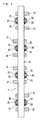
- FIG. 7 is a longitudinal sectional view illustrating a camshaft apparatus with a bearing according to the sixth embodiment of the invention.
- Fig. 8 is a transverse sectional view taken along line II-II of Fig. 7 .
- Fig. 9 is a longitudinal sectional view taken along line III-III of Fig. 7 . [0013-2]
- the camshaft apparatus (camshaft unit) mounted to a cylinder head portion of an internal combustion engine is exemplified as a shaft apparatus.
- the camshaft apparatus includes a plurality of cam blocks 614 as blocks, a plurality of roller bearings (including shell-type needle roller bearings) 620, and a plurality of pairs of control members 630, which are disposed on an outer surface of a shaft 611 in an axial direction thereof at predetermined intervals in a predetermined order so as to be unitized.
- each of the roller bearings 620 includes an outer ring 621, a number of rollers (including needle rollers) 625 using the outer surface of the shaft 611 as an inner ring raceway surface 612, and a cage 626 retaining the rollers 625.
- An outer ring raceway surface 622 is formed at an inner surface of the outer ring 621, and collars 623 protrude from both end portions of the outer ring 621 in a radial direction.
- the roller bearing 620 is fitted through an end portion of the shaft 611 at a predetermined position of the shaft 611 by using the outer surface of the shaft 611 as the inner ring raceway surface 612.
- a pair of the control members 630 for controlling the movement of the roller bearing 620 in the axial direction are press-fitted and fixed to the outer surface of the shaft 611 at positions close to both end surfaces 624 of the collars 623 of the outer ring 621 of the roller bearing 620.
- the control member 630 is formed by performing injection molding on a resin having lower hardness than the shaft 611 composed of a steel, in an annular shape, and press-fitted and fixed to the outer surface of the shaft 611.
- an outer diameter of the control member 630 is set to be smaller than an outer diameter of the outer ring 621 of the roller bearing 620.
- both end surfaces 631 of the control member 630 are formed as the same curved surfaces (including arc surfaces). Since the both end surfaces 631 of the control member 630 are formed as the same curved surfaces, when the control member 630 is press-fitted to the outer surface of the shaft 611, the end surface 631 of the control member 630 is not restricted only in a direction, and the control member 630 can be easily press-fitted and fixed.
- the end surface 631 of the control member 630 on a side is formed as the curved surface and the end surface 631 on the other side is formed as a plane surface
- the end surface 624 of the outer ring 621 may face the plane end surface on the other side and be press-fitted to the outer surface of the shaft 611.
- the both end surfaces 631 of the control member 630 are formed as the same curved surfaces (including the arc surfaces), so that the aforementioned problem does not occur.
- the cam blocks 614, the roller bearing 620, and the control member 630 are disposed in a predetermined order in a direction from an end portion to the other end portion of the outer surface of the shaft 611 in the axial direction and press-fitted and mounted to the shaft 611, thereby constituting the camshaft apparatus (see Fig. 7 ). Therefore, when the control member 630 composed of the resin is press-fitted at a predetermined position on the outer surface of the shaft 611 composed of the steel, press-fitting marks generated by press-fitting the control member 630 to the outer surface of the shaft 611 can be prevented.
- the outer diameter of the control member 630 is set to be smaller than the outer diameter of the outer ring 621 of the roller bearing 620, when the camshaft apparatus is mounted to the housing such as the cylinder head portion by tightly binding a pressing cover, the outer surface of the control member 630 is prevented from contacting the pressing cover, so that a difficulty in mounting the camshaft apparatus does not occur.
- Fig. 10 is a longitudinal sectional view illustrating a roller bearing of a shaft of a camshaft apparatus and a control member thereof which are mounted to each other according to the seventh embodiment of the invention.
- the roller bearing 720 according to the seventh embodiment includes an outer ring (shell-type outer ring) 721, a number of rollers (including needle rollers) 725 using the outer surface of the shaft 611 as an inner ring raceway surface 612, and a cage 726 for retaining the rollers 725 to roll.
- An outer ring raceway surface 722 is formed at an inner surface of the outer ring 721, and collars 723 bent into a curved shape in the radial direction are formed at both end portions of the outer ring 721.
- the roller bearing 720 is fitted through an end portion of the shaft 611 at a predetermined position of the shaft 611 by using the outer surface of the shaft 611 as the inner ring raceway surface 612.
- a pair of control members 730 for controlling the movement of the roller bearing 620 in the axial direction are press-fitted and fixed at positions close to both end surfaces (convex portions of the curved shapes) 724 of the collars 723 of the outer ring 721 of the roller bearing 720.
- both end surfaces 731 of the control members 730 are formed as plane surfaces.
- the control member 730 is formed by performing injection molding on a resin having lower hardness than the shaft 611 composed of a steel, in an annular shape as in the fifth embodiment, and press-fitted and fixed to the outer surface of the shaft 611.
- an outer diameter of the control member 730 is set to be smaller than an outer diameter of the outer ring 721 of the roller bearing 720. Since other components in the seventh embodiment are the same as those in the sixth embodiment, a detailed description thereof is omitted. Therefore, in the seventh embodiment, the same effects as in the sixth embodiment can be obtained. [0023-2]
- Fig. 11 is a longitudinal sectional view illustrating a roller bearing of a shaft of a camshaft apparatus and a control member thereof which are mounted to each other according to the eighth embodiment of the invention.
- the roller bearing 820 according to the eighth embodiment includes an outer ring 821, a number of rollers 825 using the outer surface of the shaft 611 as an inner ring raceway surface 612, and a cage 826 for retaining the rollers 825 to roll.
- An outer ring raceway surface 822 is formed at an inner surface of the outer ring 821, and collars 823 bent into a curved shape in a radial direction are formed at both end portions of the outer ring 821.
- the roller bearing 820 is fitted through an end portion of the shaft 611 at a predetermined position of the shaft 611 by using the outer surface of the shaft 611 as the inner ring raceway surface 612.
- a pair of control members 830 for controlling the movement of the roller bearing 80 in the axial direction are press-fitted and fixed at positions close to both end surfaces 827 of the cage 826 of the roller bearing 820.
- an outer diameter of the control member 830 is set to be smaller than an inner diameter of the collar 823 of the outer ring 821 of the roller bearing 820 and simultaneously equal to an outer diameter of the cage 826.
- at least one of end surfaces of the control member 830 and the cage 826 of the roller bearing 820 which face each other, is formed as a curved surface.
- the both end surfaces 827 of the cage 826 are formed as the curved surfaces (including arc surfaces), and both end surfaces 831 of the control members 830 are formed as plane surfaces.
- control member 830 is formed by performing injection molding on a resin having lower hardness than the shaft 611 composed of a steel, in an annular shape as in the sixth or seventh embodiment, and press-fitted and fixed to the outer surface of the shaft 611. Since other components in the eighth embodiment are the same as those in the sixth or seventh embodiment, a detailed description thereof is omitted. Therefore, in the eighth embodiment, the same effects as in the sixth or seventh embodiment can be obtained. [0026-2]
- the outer diameter of the control member 830 is set to be smaller than the inner diameter of the collar 823 of the outer ring 821 of the roller bearing 820, so that a compact and light-weight control member 830 can be implemented.
- the outer surface of the control member 830 can be easily prevented from contacting the pressing cover even as compared with the sixth or seventh embodiment, so that a difficulty in mounting the camshaft apparatus does not occur.
- the control member 630 (730 and 830) composed of the resin is exemplified.
- any material having lower hardness than the shaft 611 composed of the steel may be employed.
- the control member 630 (730 and 830) may be composed of a soft metal such as an aluminum material.
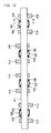
- FIG. 12 is a longitudinal sectional view illustrating a camshaft apparatus with a bearing according to the ninth embodiment of the invention.
- Fig. 13 is a transverse sectional view taken along line II-II of Fig. 12 .
- Fig. 14 is a longitudinal sectional view taken along line III-III of Fig. 13.
- Fig. 15 is a longitudinal sectional view taken along line IV - IV of Fig. 13 .
- the camshaft apparatus mounted to a cylinder head portion of an internal combustion engine is exemplified as a shaft apparatus.
- the camshaft apparatus includes a plurality of cam blocks 914 as blocks, a plurality of roller bearings (including shell-type needle roller bearings) 920, and a plurality of pairs of control members 930, which are disposed on an outer surface of a shaft 911 in an axial direction thereof at predetermined intervals in a predetermined order so as to be unitized.
- each of the roller bearings 920 includes an outer ring 921 and a number of rollers (including needle rollers) 925 using the outer surface of the shaft 911 as an inner ring raceway surface 912.
- the roller bearing 920 is any type of a roller bearing without a cage retaining the rollers 825:
- An outer ring raceway surface 922 is formed at an inner surface of the outer ring 921, and collars 923 protrude from both end portions of the outer ring 921 in a radial direction in an annular shape.
- At least one roller 925a of the rollers 925 disposed on the outer ring raceway surface 922 of the outer ring 921 is longer than the other rollers 925.
- both end surfaces 926 of the longer roller 925a are hemispherical.
- a length of the longer roller 925a is substantially equal to a distance between surfaces of the both collars 923 of the outer ring 921, which face each other.
- the roller bearing 920 is fitted through an end portion of the shaft 911 at a predetermined position of the shaft 911 by using the outer surface of the shaft 911 as the inner ring raceway surface 912.
- a cylindrical control member 930 for controlling the movement of the roller bearing 920 in the axial direction is press-fitted and fixed at a position close to the both end surfaces 926 of the longer roller 925a among the rollers 925 of the roller bearing 920.
- the control member 930 is formed by performing injection molding on a resin having lower hardness than the shaft 911 composed of a steel, and includes a cylindrical portion 931 press-fitted and fixed to the outer surface of the shaft 911 and a flange portion 932 protruding from an outer surface of an end portion of the cylindrical portion 931 in an annular shape in one body.
- An outer diameter of the flange unit 932 of the control member 930 is set to be smaller than an outer diameter of the outer ring 921 of the roller bearing 920.
- the flange portion 932 of the control member 930 is pressed in the axial direction by a press-fit tool, so that the control member 930 can be easily press-fitted and fixed at a predetermined position on the outer surface of the shaft 911.
- the control member 930 is composed of the resin, when the control member 930 composed of the resin is press-fitted at a predetermined position on the outer surface of the shaft 811 composed of the steel, press-fitting marks generated by press-fitting the control member 930 to the outer surface of the shaft 911 can be prevented.
- the camshaft apparatus can be easily mounted to the housing such as the cylinder head portion.
- the longer roller 925a is forcibly contacted to the end surface of the cylindrical portion 931 of the control member 930 and the inner surface of the collar 923 of the outer ring 921, and the other rollers 925 are free in the axial direction, so that abrasion between contacting portions due to the rotary torque of the bearing can be reduced.
- the outer diameter of the flange portion 932 of the control member 930 is set to be smaller than the outer diameter of the outer ring 921 of the roller bearing 920, when the camshaft apparatus is mounted to the housing such as the cylinder head portion by tightly binding a pressing cover, an outer surface of the flange portion 932 of the control member 930 is prevented from contacting the pressing cover, so that a difficulty in mounting the camshaft apparatus is not caused.
- control member 930 is composed of the resin.
- any material having lower hardness than the shaft 911 composed of the steel may be employed.
- the control member 930 may be composed of a soft metal such as an aluminum material.
- the roller bearing without a cage is exemplified. However, a bearing using the cage may be applied.
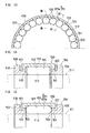
- FIG. 16 is a longitudinal sectional view illustrating a bearing apparatus for a camshaft according to the tenth embodiment of the invention.
- Fig. 17 is a transverse sectional view taken along line II-II of Fig. 16 .
- Fig. 18 is an explanatory view illustrating a state before a roller bearing and first and second control rings are mounted to the camshaft.
- Fig. 19 is an explanatory view illustrating a state before the camshaft is assumed between a housing member and a cap member. [0009-4] As illustrated in Figs.
- the bearing apparatus for a camshaft includes the camshaft 1011, the roller bearing 1020, the first and second control rings 1030 and 1035, the housing member 1040, and the cap member 1050.
- a plurality of cam blocks 1014 are disposed on the outer surface of the camshaft 1011 in an axial direction, and a bearing (roller bearing or sliding bearing) 1015 is disposed between the adjacent cam blocks 1014 on the outer surface of the camshaft 1011 as needed.
- the roller bearing 1020 and the first and second control rings 1030 and 1035 are mounted to an outer surface of an end gathered portion of the camshaft 11. As illustrated in Figs.
- the roller bearing (including shell-type needle roller bearing) 1020 includes an outer ring 1021, a number of rollers (including needle rollers) 1025 using the outer surface of the camshaft 1011 as an inner ring raceway surface 1012, and a cage 1026 for retaining the rollers 1025.
- the roller bearing 1020 is fitted through an axial end portion of the camshaft 1011 at a predetermined portion on the outer surface of the camshaft 1011.
- the first and second control rings 1030 and 1035 that are separately provided from the camshaft 1011 are composed of a steel, a nonferrous metal, a resin, or the like and formed in an annular shape so as to be press-fitted and fixed to the outer surface of the camshaft 1011 at both side portions of the roller bearing 1020 in the axial direction.
- a distance between surfaces of the first and second control rings 1030 and 1035 press-fitted and fixed to the outer surface of the camshaft 1011 which face each other is set to be slightly larger than a distance (or distance between both side surfaces 1052 of the cap member 1050) between both side surfaces 1042 of the housing member 1040 described later.
- first and second control rings 1030 and 1035 facing each other serve as slide surfaces 1031 and 1036 with respect to the both side surfaces 1042 of the housing member 1040 and the both side surfaces 1052 of the cap member 1050.
- the outer diameters of the first and second control rings 1030 and 1035 are set to provide gaps S1 and S2 between outer surfaces of the first and second control rings 1030 and 1035 and the housing member 1040 and the cap member 1050, respectively, through which a lubricant can be injected.
- the first and second control rings 1030 and 35 may be composed of a material having lower hardness than the camshaft 1011 in order to prevent marks generated by performing press-fitting on the shaft 1011 composed of the steel.
- a shaft mounting portion of a surface of the housing member 1040 of a cylinder head portion of an internal combustion engine is provided with a stepped concave arc having a center portion in the axial direction as a minor diameter and both sides as major diameters is formed.
- an arc concave portion 1041 formed in a half arc shape having a diameter substantially equal to an outer diameter of the outer ring 1021 of the roller bearing 1020 is formed.
- the gap S1 is provided.
- interval threads 1047 to which bolts 1060 for tightening the cap member 1050 are mounted are formed at both end portions of the arc concave portion 1041 of the shaft mounting portion.
- the cap member 1050 is provided with a stepped concave arc having a center portion in the axial direction as a minor diameter and both sides as major diameters, similarly to the shaft mounting portion of the housing member 1040.
- an arc concave portion 1051 formed in a half arc shape having a diameter substantially equal to the outer diameter of the outer ring 1021 of the roller bearing 1020 is formed.
- the gap S2 is provided between inner surfaces of shoulder portions 1055 on both sides and the outer surfaces of the first and second control rings 1030 and 1035.
- attached pieces 1056 having through-holes 1057 through which the bolts 1060 at the both end portions of the arc concave portion 1051 are inserted are formed at the cap member 1050.
- the housing member 1040 and the cap member 1050 are tightened by the bolt 1060, so that the camshaft 1011 can be rotatably mounted with the roller bearing 1020 interposed between the arc concave portions 1041 and 1051 of the housing member 1040 and the cap member 1050.
- the slide surfaces 1031 and 1036 of the first and second control rings 1030 and 1035 on the camshaft 1011 facing each other are disposed at positions close to the both side surfaces 1042 of the housing member 1040 and the both side surfaces 1052 of the cap member 1050.
- FIG. 20 is a longitudinal sectional view illustrating a bearing apparatus for a camshaft according to the eleventh embodiment of the invention.
- annular walls 1145 protrude from both side portions of an arc concave portion 1141 formed at a center portion in the axial direction of a shaft mounting portion of a housing member 1140, toward the center of the shaft.
- annular walls 1155 protrude from both side portions of an arc concave portion 1151 of a center portion in the axial direction of a cap member 1150, toward the center of the shaft.
- the roller bearing 1120 and first and second control rings 1130 and 1135 are mounted to an outer surface of a camshaft 1111 as in the eleventh embodiment.
- slide surfaces 1131 and 1136 of the first and second control rings 1130 and 1135 on the camshaft 1111, which face each other are disposed at positions close to side surfaces 1142 of the both annular walls 1145 of the housing member 1140 and side surfaces 1152 of the both annular walls 1155 of the cap member 1150. Therefore, in the eleventh embodiment, the same effects as in the tenth embodiment can be obtained.
- the present invention is not limited to the first to eleventh embodiments and may be modified in various formed without departing from the spirit and scope of the invention.
- the camshaft apparatus 11 is exemplified as the shaft apparatus.
- a bearing-attached balance shaft apparatus having a weight member as a block or a crankshaft apparatus may be exemplified.
Priority Applications (1)
| Application Number | Priority Date | Filing Date | Title |
|---|---|---|---|
| EP10015693A EP2302241B1 (de) | 2007-11-27 | 2008-11-25 | Wellenvorrichtung mit Rollenlager |
Applications Claiming Priority (4)
| Application Number | Priority Date | Filing Date | Title |
|---|---|---|---|
| JP2007305794A JP2009127808A (ja) | 2007-11-27 | 2007-11-27 | 軸受付きシャフト装置 |
| JP2008031590A JP2009191893A (ja) | 2008-02-13 | 2008-02-13 | 軸受付きシャフト装置 |
| JP2008031589A JP2009191892A (ja) | 2008-02-13 | 2008-02-13 | 軸受付きシャフト装置 |
| JP2008080599A JP5050954B2 (ja) | 2008-03-26 | 2008-03-26 | カムシャフトの軸受装置 |
Related Child Applications (1)
| Application Number | Title | Priority Date | Filing Date |
|---|---|---|---|
| EP10015693.4 Division-Into | 2010-12-15 |
Publications (2)
| Publication Number | Publication Date |
|---|---|
| EP2065603A1 true EP2065603A1 (de) | 2009-06-03 |
| EP2065603B1 EP2065603B1 (de) | 2011-11-02 |
Family
ID=40342668
Family Applications (2)
| Application Number | Title | Priority Date | Filing Date |
|---|---|---|---|
| EP10015693A Expired - Fee Related EP2302241B1 (de) | 2007-11-27 | 2008-11-25 | Wellenvorrichtung mit Rollenlager |
| EP08020443A Expired - Fee Related EP2065603B1 (de) | 2007-11-27 | 2008-11-25 | Wellenvorrichtung mit Rollenlager |
Family Applications Before (1)
| Application Number | Title | Priority Date | Filing Date |
|---|---|---|---|
| EP10015693A Expired - Fee Related EP2302241B1 (de) | 2007-11-27 | 2008-11-25 | Wellenvorrichtung mit Rollenlager |
Country Status (2)
| Country | Link |
|---|---|
| US (2) | US20090133528A1 (de) |
| EP (2) | EP2302241B1 (de) |
Cited By (7)
| Publication number | Priority date | Publication date | Assignee | Title |
|---|---|---|---|---|
| CN103061837A (zh) * | 2011-08-24 | 2013-04-24 | 马勒国际有限公司 | 轴承座 |
| WO2014142837A1 (en) * | 2013-03-13 | 2014-09-18 | Koyo Bearings Usa Llc | Axially self-positioning radial support bearing |
| US8991359B2 (en) | 2010-09-03 | 2015-03-31 | Jtekt Corporation | Camshaft device |
| WO2016040821A1 (en) * | 2014-09-11 | 2016-03-17 | Koyo Bearings North America Llc | Axle wheel end axial thrust assembly |
| CN105545948A (zh) * | 2016-01-29 | 2016-05-04 | 万向钱潮股份有限公司 | 一种能轴向移动的滚针轴承 |
| WO2017211804A3 (de) * | 2016-06-07 | 2018-02-01 | Thyssenkrupp Presta Teccenter Ag | Verfahren zur herstellung einer gebauten nockenwelle einer brennkraftmaschine |
| WO2019170191A1 (de) * | 2018-03-07 | 2019-09-12 | Schaeffler Technologies AG & Co. KG | Ausgleichswelle |
Families Citing this family (13)
| Publication number | Priority date | Publication date | Assignee | Title |
|---|---|---|---|---|
| DE102009009665A1 (de) * | 2009-02-19 | 2010-08-26 | Mahle International Gmbh | Brennkraftmaschine mit wenigstens einer Nockenwelle |
| DE102011081483A1 (de) * | 2011-08-24 | 2013-02-28 | Mahle International Gmbh | Verfahren zur vereinfachten und lagegenauen Fixierung eines Nockenwellenmoduls an einem Zylinderkopf |
| DE102011081486A1 (de) * | 2011-08-24 | 2013-02-28 | Mahle International Gmbh | Kurbelgehäuse |
| DE102011088603A1 (de) | 2011-12-14 | 2013-06-20 | Mahle International Gmbh | Welle-/Lageranordnung |
| DE102011088655A1 (de) | 2011-12-15 | 2013-06-20 | Schaeffler Technologies AG & Co. KG | Wälzlagerung für eine gebaute Nockenwelle |
| DE102013203842A1 (de) * | 2013-03-06 | 2014-09-11 | Mahle International Gmbh | Lageranordnung |
| DE102014213996B4 (de) * | 2014-07-18 | 2017-08-24 | Aktiebolaget Skf | Wälzlager mit schräger Lauffläche |
| US20160069392A1 (en) * | 2014-09-10 | 2016-03-10 | Schaeffler Technologies AG & Co. KG | Radial bearing with variable lubrication flow restriction |
| JP6379079B2 (ja) * | 2015-10-01 | 2018-08-22 | 透一 野渡 | ラジアルころ軸受 |
| DE102016203594A1 (de) * | 2016-03-04 | 2017-09-07 | Mahle International Gmbh | Vormontierte Lagerbaugruppe |
| DE102018112427A1 (de) * | 2018-05-24 | 2019-11-28 | Schaeffler Technologies AG & Co. KG | Zylinderrollenlager |
| US20200300349A1 (en) * | 2019-03-18 | 2020-09-24 | Otics Corporation | Camshaft assembly support structure |
| FR3094050B1 (fr) * | 2019-03-18 | 2021-02-19 | Skf Aerospace France | Ensemble de roulement à éléments roulants cylindriques |
Citations (10)
| Publication number | Priority date | Publication date | Assignee | Title |
|---|---|---|---|---|
| DE923760C (de) * | 1953-05-13 | 1955-02-21 | Duerkoppwerke Ag | Nadellager mit Kaefig und Laufring |
| FR1518002A (fr) * | 1967-02-10 | 1968-03-22 | Nadella | Roulement pouvant fixer la position axiale d'un élément de machine |
| FR2506869A1 (fr) * | 1981-05-30 | 1982-12-03 | Schaeffler Ohg Industriewerk | Palier a roulement |
| JPH0874523A (ja) * | 1994-09-01 | 1996-03-19 | Daihatsu Motor Co Ltd | 内燃機関におけるカム軸の軸受け装置 |
| DE102006036851A1 (de) * | 2005-08-05 | 2007-06-28 | Neumayer Tekfor Holding Gmbh | Welle wie Nockenwelle für Brennkraftmaschinen, Verfahren zur Herstellung solcher Wellen, sowie damit ausgerüstete Brennkraftmaschinen |
| JP2007187259A (ja) | 2006-01-13 | 2007-07-26 | Nsk Ltd | 分割型ころ軸受 |
| JP2007192315A (ja) | 2006-01-19 | 2007-08-02 | Nsk Ltd | 分割型ころ軸受 |
| JP2007247875A (ja) | 2006-03-20 | 2007-09-27 | Jtekt Corp | 分割型ころ軸受装置 |
| FR2913720A1 (fr) * | 2007-03-16 | 2008-09-19 | Timken Co | Arbre a cames |
| EP1995417A1 (de) * | 2007-05-22 | 2008-11-26 | Mahle International GmbH | Nockenwelle |
Family Cites Families (19)
| Publication number | Priority date | Publication date | Assignee | Title |
|---|---|---|---|---|
| US2697403A (en) * | 1949-06-06 | 1954-12-21 | Melba L Benedek | Hydraulic pump or motor |
| US2703738A (en) * | 1952-01-05 | 1955-03-08 | Skf Ind Inc | Cylindrical roller bearings |
| US2682435A (en) * | 1953-07-17 | 1954-06-29 | Walter G Rien | Split roller bearing assembly |
| DE1255994B (de) * | 1963-01-25 | 1967-12-07 | Schaeffler Ohg Industriewerk | Waelzlager fuer zylindrische Waelzkoerper |
| US3307891A (en) * | 1964-12-31 | 1967-03-07 | Torrington Co | Prestressed roller bearing |
| FR2129088A5 (de) * | 1971-03-15 | 1972-10-27 | Pitner Alfred | |
| JPH0499420A (ja) | 1990-08-20 | 1992-03-31 | Nobuo Matsubara | 稲の栽培と海水の塩精製と醸造体験と鶏の飼育を介して信仰像を養成する装置と信仰活動方法 |
| JPH09242511A (ja) | 1996-03-06 | 1997-09-16 | Isuzu Motors Ltd | カム軸のスラスト軸受構造 |
| DE19926406A1 (de) * | 1999-06-10 | 2000-12-14 | Schaeffler Waelzlager Ohg | Lagerung einer Welle mit geteilten Wälzlagern |
| JP2000320646A (ja) | 1999-05-07 | 2000-11-24 | Ntn Corp | カムフォロア |
| US6176623B1 (en) * | 1999-09-08 | 2001-01-23 | The Torrington Company | Flange piloted drawn inverted roller bearing |
| JP2003222226A (ja) | 2002-01-30 | 2003-08-08 | Ntn Corp | ピストン駆動装置 |
| JP2004316671A (ja) | 2003-04-11 | 2004-11-11 | Ntn Corp | 内輪付きシェル型ころ軸受 |
| US7311447B2 (en) * | 2003-09-19 | 2007-12-25 | Nsk Ltd. | Roller bearing |
| US7172352B2 (en) * | 2003-12-09 | 2007-02-06 | Hewlett-Packard Development Company, L.P. | Bearing |
| JP2006052775A (ja) | 2004-08-11 | 2006-02-23 | Ntn Corp | カムフォロア |
| JP2006226183A (ja) | 2005-02-17 | 2006-08-31 | Jtekt Corp | カムシャフト装置とその組立方法 |
| JP2006226184A (ja) | 2005-02-17 | 2006-08-31 | Jtekt Corp | カムシャフト装置及びその組立方法 |
| JP2008232310A (ja) * | 2007-03-21 | 2008-10-02 | Jtekt Corp | ころ軸受 |
-
2008
- 2008-11-25 EP EP10015693A patent/EP2302241B1/de not_active Expired - Fee Related
- 2008-11-25 EP EP08020443A patent/EP2065603B1/de not_active Expired - Fee Related
- 2008-11-25 US US12/292,735 patent/US20090133528A1/en not_active Abandoned
-
2011
- 2011-03-21 US US13/064,353 patent/US8539860B2/en active Active
Patent Citations (10)
| Publication number | Priority date | Publication date | Assignee | Title |
|---|---|---|---|---|
| DE923760C (de) * | 1953-05-13 | 1955-02-21 | Duerkoppwerke Ag | Nadellager mit Kaefig und Laufring |
| FR1518002A (fr) * | 1967-02-10 | 1968-03-22 | Nadella | Roulement pouvant fixer la position axiale d'un élément de machine |
| FR2506869A1 (fr) * | 1981-05-30 | 1982-12-03 | Schaeffler Ohg Industriewerk | Palier a roulement |
| JPH0874523A (ja) * | 1994-09-01 | 1996-03-19 | Daihatsu Motor Co Ltd | 内燃機関におけるカム軸の軸受け装置 |
| DE102006036851A1 (de) * | 2005-08-05 | 2007-06-28 | Neumayer Tekfor Holding Gmbh | Welle wie Nockenwelle für Brennkraftmaschinen, Verfahren zur Herstellung solcher Wellen, sowie damit ausgerüstete Brennkraftmaschinen |
| JP2007187259A (ja) | 2006-01-13 | 2007-07-26 | Nsk Ltd | 分割型ころ軸受 |
| JP2007192315A (ja) | 2006-01-19 | 2007-08-02 | Nsk Ltd | 分割型ころ軸受 |
| JP2007247875A (ja) | 2006-03-20 | 2007-09-27 | Jtekt Corp | 分割型ころ軸受装置 |
| FR2913720A1 (fr) * | 2007-03-16 | 2008-09-19 | Timken Co | Arbre a cames |
| EP1995417A1 (de) * | 2007-05-22 | 2008-11-26 | Mahle International GmbH | Nockenwelle |
Cited By (11)
| Publication number | Priority date | Publication date | Assignee | Title |
|---|---|---|---|---|
| US8991359B2 (en) | 2010-09-03 | 2015-03-31 | Jtekt Corporation | Camshaft device |
| CN103061837A (zh) * | 2011-08-24 | 2013-04-24 | 马勒国际有限公司 | 轴承座 |
| CN103061837B (zh) * | 2011-08-24 | 2016-12-21 | 马勒国际有限公司 | 轴承座 |
| WO2014142837A1 (en) * | 2013-03-13 | 2014-09-18 | Koyo Bearings Usa Llc | Axially self-positioning radial support bearing |
| US9850947B2 (en) | 2013-03-13 | 2017-12-26 | Koyo Bearings North America Llc | Axially self-positioning radial support bearing |
| WO2016040821A1 (en) * | 2014-09-11 | 2016-03-17 | Koyo Bearings North America Llc | Axle wheel end axial thrust assembly |
| US11794522B2 (en) | 2014-09-11 | 2023-10-24 | Jtekt Bearings North America Llc | Axle wheel end axial thrust assembly |
| CN105545948A (zh) * | 2016-01-29 | 2016-05-04 | 万向钱潮股份有限公司 | 一种能轴向移动的滚针轴承 |
| WO2017211804A3 (de) * | 2016-06-07 | 2018-02-01 | Thyssenkrupp Presta Teccenter Ag | Verfahren zur herstellung einer gebauten nockenwelle einer brennkraftmaschine |
| US11267086B2 (en) | 2016-06-07 | 2022-03-08 | Thyssenkrupp Presta Teccenter Ag | Method for producing a constructed camshaft of an internal combustion engine |
| WO2019170191A1 (de) * | 2018-03-07 | 2019-09-12 | Schaeffler Technologies AG & Co. KG | Ausgleichswelle |
Also Published As
| Publication number | Publication date |
|---|---|
| US8539860B2 (en) | 2013-09-24 |
| US20090133528A1 (en) | 2009-05-28 |
| EP2065603B1 (de) | 2011-11-02 |
| US20110197702A1 (en) | 2011-08-18 |
| EP2302241B1 (de) | 2013-02-20 |
| EP2302241A1 (de) | 2011-03-30 |
Similar Documents
| Publication | Publication Date | Title |
|---|---|---|
| EP2065603B1 (de) | Wellenvorrichtung mit Rollenlager | |
| US20090126195A1 (en) | Roller bearing | |
| US8051821B2 (en) | Camshaft apparatus | |
| EP2588769B1 (de) | Vorrichtung mit einem kegelrollenlager | |
| WO2013108433A1 (ja) | カムフォロア装置 | |
| US8393800B2 (en) | Needle roller bearing and crankshaft support structure | |
| JP2009014078A (ja) | 針状ころ軸受、およびクランクシャフト支持構造 | |
| US20090137327A1 (en) | Shaft apparatus with bearing | |
| JP5762698B2 (ja) | 分割型ニードル軸受及び軸受装置 | |
| JP5064910B2 (ja) | 針状ころ軸受、およびクランクシャフト支持構造 | |
| JP5050954B2 (ja) | カムシャフトの軸受装置 | |
| JP2009127807A (ja) | 軸受付きカムシャフト装置と組付構造 | |
| EP2341260A2 (de) | Einstellbare Lagerbefestigung | |
| JP2019183888A (ja) | 回転軸の軸受支持構造 | |
| JP2009036329A (ja) | 針状ころ軸受の回転軸への組み込み方法 | |
| JPH11182542A (ja) | 調心輪付き転がり軸受 | |
| JP5071452B2 (ja) | クランク軸用軸受装置 | |
| JP2010001809A (ja) | カムシャフトおよびカムシャフトの製造方法 | |
| JP2010025011A (ja) | カムシャフト装置 | |
| JP2022540981A (ja) | 締まりばめを有する二つの部品の複合の円錐ころ軸受外輪及び製造方法 | |
| JP2009191892A (ja) | 軸受付きシャフト装置 | |
| JP4457582B2 (ja) | 一方向クラッチ内蔵型プーリ装置 | |
| CN115298449A (zh) | 从动轴承 | |
| JP2005120985A (ja) | 軸受装置 | |
| JP2009014077A (ja) | 針状ころ軸受、およびクランクシャフト支持構造 |
Legal Events
| Date | Code | Title | Description |
|---|---|---|---|
| PUAI | Public reference made under article 153(3) epc to a published international application that has entered the european phase |
Free format text: ORIGINAL CODE: 0009012 |
|
| AK | Designated contracting states |
Kind code of ref document: A1 Designated state(s): AT BE BG CH CY CZ DE DK EE ES FI FR GB GR HR HU IE IS IT LI LT LU LV MC MT NL NO PL PT RO SE SI SK TR |
|
| AX | Request for extension of the european patent |
Extension state: AL BA MK RS |
|
| 17P | Request for examination filed |
Effective date: 20091203 |
|
| AKX | Designation fees paid |
Designated state(s): DE FR |
|
| 17Q | First examination report despatched |
Effective date: 20100716 |
|
| GRAP | Despatch of communication of intention to grant a patent |
Free format text: ORIGINAL CODE: EPIDOSNIGR1 |
|
| GRAS | Grant fee paid |
Free format text: ORIGINAL CODE: EPIDOSNIGR3 |
|
| GRAA | (expected) grant |
Free format text: ORIGINAL CODE: 0009210 |
|
| AK | Designated contracting states |
Kind code of ref document: B1 Designated state(s): DE FR |
|
| REG | Reference to a national code |
Ref country code: DE Ref legal event code: R096 Ref document number: 602008011002 Country of ref document: DE Effective date: 20111229 |
|
| PLBE | No opposition filed within time limit |
Free format text: ORIGINAL CODE: 0009261 |
|
| STAA | Information on the status of an ep patent application or granted ep patent |
Free format text: STATUS: NO OPPOSITION FILED WITHIN TIME LIMIT |
|
| 26N | No opposition filed |
Effective date: 20120803 |
|
| REG | Reference to a national code |
Ref country code: DE Ref legal event code: R097 Ref document number: 602008011002 Country of ref document: DE Effective date: 20120803 |
|
| PGFP | Annual fee paid to national office [announced via postgrant information from national office to epo] |
Ref country code: FR Payment date: 20141110 Year of fee payment: 7 |
|
| REG | Reference to a national code |
Ref country code: FR Ref legal event code: ST Effective date: 20160729 |
|
| PG25 | Lapsed in a contracting state [announced via postgrant information from national office to epo] |
Ref country code: FR Free format text: LAPSE BECAUSE OF NON-PAYMENT OF DUE FEES Effective date: 20151130 |
|
| PGFP | Annual fee paid to national office [announced via postgrant information from national office to epo] |
Ref country code: DE Payment date: 20201110 Year of fee payment: 13 |
|
| REG | Reference to a national code |
Ref country code: DE Ref legal event code: R119 Ref document number: 602008011002 Country of ref document: DE |
|
| PG25 | Lapsed in a contracting state [announced via postgrant information from national office to epo] |
Ref country code: DE Free format text: LAPSE BECAUSE OF NON-PAYMENT OF DUE FEES Effective date: 20220601 |