EP2065524A2 - Drainage device - Google Patents
Drainage device Download PDFInfo
- Publication number
- EP2065524A2 EP2065524A2 EP08020387A EP08020387A EP2065524A2 EP 2065524 A2 EP2065524 A2 EP 2065524A2 EP 08020387 A EP08020387 A EP 08020387A EP 08020387 A EP08020387 A EP 08020387A EP 2065524 A2 EP2065524 A2 EP 2065524A2
- Authority
- EP
- European Patent Office
- Prior art keywords
- drainage device
- shaped
- drain body
- channel
- plate
- Prior art date
- Legal status (The legal status is an assumption and is not a legal conclusion. Google has not performed a legal analysis and makes no representation as to the accuracy of the status listed.)
- Granted
Links
- 239000002351 wastewater Substances 0.000 claims abstract description 11
- 229910000831 Steel Inorganic materials 0.000 claims abstract description 3
- 239000010959 steel Substances 0.000 claims abstract description 3
- 239000002184 metal Substances 0.000 claims abstract 2
- 238000009434 installation Methods 0.000 claims description 5
- 238000007789 sealing Methods 0.000 claims description 3
- 238000005266 casting Methods 0.000 claims description 2
- 229910052500 inorganic mineral Inorganic materials 0.000 claims description 2
- 239000011707 mineral Substances 0.000 claims description 2
- 230000037431 insertion Effects 0.000 claims 1
- 238000003780 insertion Methods 0.000 claims 1
- 239000002023 wood Substances 0.000 description 2
- 238000004026 adhesive bonding Methods 0.000 description 1
- 239000000463 material Substances 0.000 description 1
Images

Classifications
-
- E—FIXED CONSTRUCTIONS
- E03—WATER SUPPLY; SEWERAGE
- E03F—SEWERS; CESSPOOLS
- E03F5/00—Sewerage structures
- E03F5/04—Gullies inlets, road sinks, floor drains with or without odour seals or sediment traps
- E03F5/0407—Floor drains for indoor use
- E03F5/0408—Floor drains for indoor use specially adapted for showers
-
- A—HUMAN NECESSITIES
- A47—FURNITURE; DOMESTIC ARTICLES OR APPLIANCES; COFFEE MILLS; SPICE MILLS; SUCTION CLEANERS IN GENERAL
- A47K—SANITARY EQUIPMENT NOT OTHERWISE PROVIDED FOR; TOILET ACCESSORIES
- A47K3/00—Baths; Douches; Appurtenances therefor
- A47K3/28—Showers or bathing douches
- A47K3/40—Pans or trays
- A47K3/405—Pans or trays flush with the surrounding floor, e.g. for easy access
-
- E—FIXED CONSTRUCTIONS
- E03—WATER SUPPLY; SEWERAGE
- E03F—SEWERS; CESSPOOLS
- E03F3/00—Sewer pipe-line systems
- E03F3/04—Pipes or fittings specially adapted to sewers
- E03F3/046—Open sewage channels
-
- E—FIXED CONSTRUCTIONS
- E03—WATER SUPPLY; SEWERAGE
- E03F—SEWERS; CESSPOOLS
- E03F5/00—Sewerage structures
- E03F5/04—Gullies inlets, road sinks, floor drains with or without odour seals or sediment traps
- E03F2005/0416—Gullies inlets, road sinks, floor drains with or without odour seals or sediment traps with an odour seal
Definitions
- the present invention relates to a drainage device for a wet room, in particular for a shower, according to the preamble of claim 1. Furthermore, the present invention relates to a drainage device for a wet room, in particular for a shower, according to the preamble of claim 15th
- Such drain devices are known. For example, they are used for barrier-free showers.
- the plate-shaped parts can serve as a support surface for tiles, for example, or even be part of the surface of the shower floor itself.
- a disadvantage of such drainage devices proves the usually very complicated installation.
- the problem underlying the present invention is to provide a drain device of the type mentioned, which is easier to install.
- Another problem underlying the present invention is the provision of a drainage device of the type mentioned above, which offers a more attractive appearance and / or in which the waste water can easily enter the inlet opening.
- the trough-shaped drain body and the at least partially plate-shaped part are pre-assembled to a unit. As a result, the assembly is much easier.
- the gutter-shaped drain body and the at least partially plate-shaped part can be detachably and / or permanently connected to one another, in particular glued together and / or screwed.
- the trough-shaped drain body is arranged in the plate-shaped part and in the installation position, in particular neither protrudes above nor below the plate-shaped part. As a result, the preassembled unit of trough-shaped drain body and plate-shaped part can be easily stacked.
- the channel-shaped drain body has at least one chamfer in the region of the inlet opening.
- the bevel promotes the entry of the wastewater into the inlet opening.
- the chamfer can continue an example provided in the plate-shaped part bevel, so that there is an attractive appearance of the drainage device.
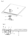
- the from the Figures 1 and 2 apparent drainage device essentially comprises a gutter-shaped drain body 1, an at least partially plate-shaped part 2 and a drain pot. 3
- the gutter-shaped drain body 1 consists for example of plastic and / or steel and has in the position of use an upper elongated inlet opening (not shown) through which Wastewater can enter the gutter.
- a cover element (not shown) can be arranged in or on the channel.
- the inlet opening may extend between the channel and the cover element, in particular around the cover element.
- a nozzle 4 is formed or attached, which has an outlet opening 5, through which the wastewater located in the gutter can escape.
- the at least partially plate-shaped part 2 may for example consist of mineral casting.
- materials conceivable that can serve as a surface for a shower area For example, wood, preferably impregnated wood, could also be used.
- the at least partially plate-shaped part 2 can have a finished, upper surface in the installed position, so that it can itself form the surface of the shower area. As a result, the assembly is significantly simplified, because after installation of the connected to the drain body 1 Part 2 no further action must be taken to achieve an attractive surface of the shower area.
- the at least partially plate-shaped part 2 serves as a support surface for tiles or another floor covering.
- trough-shaped drain body 1 and the at least partially plate-shaped part 2 are preassembled into a unit. This can be realized for example by gluing and / or screwing.
- the drain pot 3 can be preassembled in the bottom of the damp room.
- the drain pot 3 has a drain port 6, which can be connected to a drain line.
- drain port 6 In the open-top drain pot 3 can be introduced 4 as part of the assembly.
- drain pan 3 and trough-shaped drain body 1 can be screwed together.
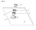
- This embodiment is designed so that the trough-shaped drain body 1 can be arranged in the plate-shaped part 2.
- the underside of the drain body 1 in the preassembled state is flush with the underside of the plate-shaped part 2 (see Fig. 5 ).
- the top of the drain body 1 in the preassembled state is flush with the top of the plate-shaped part 2 from. Due to the fact that the trough-shaped drain body 1 is arranged in the plate-shaped part 2 and protrudes in the installation position neither down nor up over the plate-shaped part 2, the preassembled unit can be easily stacked.
- a sealing insert 7 can be screwed, which can be inserted into the drain pan 3 from above.
- an odor trap unit 8 shown, which can be introduced from above into the gutter-shaped drain body 1.
- the drain body 1 also has a lateral chamfer 9, which corresponds to a chamfer 10 of the plate-shaped part 2.
- bevel 9 is on the one hand entering the waste water in the inlet opening 11 favors.
- the chamfer 9 continues the chamfer 10 provided in the plate-shaped part 2, so that an appealing appearance of the drainage device results.
Abstract
Description
Die vorliegende Erfindung betrifft eine Ablaufvorrichtung für einen Feuchtraum, insbesondere für eine Dusche, gemäß dem Oberbegriff des Anspruchs 1. Weiterhin betrifft die vorliegende Erfindung eine Ablaufvorrichtung für einen Feuchtraum, insbesondere für eine Dusche, gemäß dem Oberbegriff des Anspruchs 15.The present invention relates to a drainage device for a wet room, in particular for a shower, according to the preamble of
Derartige Ablaufvorrichtungen sind bekannt. Sie finden beispielsweise bei barrierefreien Duschen Verwendung. Dabei können die plattenförmigen Teile beispielsweise als Auflagefläche für Fliesen dienen oder bereits selbst Teil der Oberfläche des Duschenbodens sein. Als nachteilig bei derartigen Ablaufvorrichtungen erweist sich die in der Regel sehr umständliche Montage.Such drain devices are known. For example, they are used for barrier-free showers. The plate-shaped parts can serve as a support surface for tiles, for example, or even be part of the surface of the shower floor itself. A disadvantage of such drainage devices proves the usually very complicated installation.
Das der vorliegenden Erfindung zugrunde liegende Problem ist die Schaffung einer Ablaufvorrichtung der eingangs genannten Art, die einfacher montierbar ist. Ein weiteres der vorliegenden Erfindung zugrunde liegende Problem ist die Schaffung einer Ablaufvorrichtung der eingangs genannten Art, die ein ansprechenderes Äußeres bietet und/oder bei der das Abwasser einfacher in die Einlauföffnung eintreten kann.The problem underlying the present invention is to provide a drain device of the type mentioned, which is easier to install. Another problem underlying the present invention is the provision of a drainage device of the type mentioned above, which offers a more attractive appearance and / or in which the waste water can easily enter the inlet opening.
Dies wird erfindungsgemäß durch eine Ablaufvorrichtung der eingangs genannten Art mit den kennzeichnenden Merkmalen des Anspruchs 1 und durch eine Ablaufvorrichtung der eingangs genannten Art mit den kennzeichnenden Merkmalen des Anspruchs 15 erreicht. Die Unteransprüche betreffen bevorzugte Ausgestaltungen der Erfindung.This is inventively achieved by a drain device of the type mentioned above with the characterizing features of
Gemäß Anspruch 1 ist vorgesehen, dass der rinnenförmige Ablaufkörper und das zumindest abschnittsweise plattenförmige Teil zu einer Einheit vormontiert sind. Dadurch wird die Montage wesentlich erleichtert.According to
Beispielsweise können dabei der rinnenförmige Ablaufkörper und das zumindest abschnittsweise plattenförmige Teil lösbar und/oder unlösbar miteinander verbunden sein, insbesondere miteinander verklebt und/oder verschraubt sein.For example, the gutter-shaped drain body and the at least partially plate-shaped part can be detachably and / or permanently connected to one another, in particular glued together and / or screwed.
Es kann vorgesehen sein, dass der rinnenförmige Ablaufkörper in dem plattenförmigen Teil angeordnet ist und in Einbaulage insbesondere weder oben noch unten über das plattenförmige Teil hinausragt. Dadurch lässt sich die vormontierte Einheit aus rinnenförmigem Ablaufkörper und plattenförmigem Teil problemlos stapeln.It can be provided that the trough-shaped drain body is arranged in the plate-shaped part and in the installation position, in particular neither protrudes above nor below the plate-shaped part. As a result, the preassembled unit of trough-shaped drain body and plate-shaped part can be easily stacked.
Gemäß Anspruch 15 ist vorgesehen, dass der rinnenförmige Ablaufkörper im Bereich der Einlauföffnung mindestens eine Anschrägung aufweist. Durch die Anschrägung wird das Eintreten des Abwassers in die Einlauföffnung begünstigt. Weiterhin kann die Anschrägung eine beispielsweise in dem plattenförmigen Teil vorgesehene Anschrägung fortsetzen, so dass sich ein ansprechendes Äußeres der Ablaufvorrichtung ergibt.According to claim 15, it is provided that the channel-shaped drain body has at least one chamfer in the region of the inlet opening. The bevel promotes the entry of the wastewater into the inlet opening. Furthermore, the chamfer can continue an example provided in the plate-shaped part bevel, so that there is an attractive appearance of the drainage device.
Weitere Merkmale und Vorteile der vorliegenden Erfindung werden deutlich anhand der nachfolgenden Beschreibung bevorzugter Ausführungsbeispiele unter Bezugnahme auf die beiliegenden Abbildungen. Darin zeigen
- Fig. 1
- eine perspektivische Explosionsdarstellung einer ersten Ausführungsform einer erfindungsgemäßen Ablaufvorrichtung;
- Fig. 2
- eine weitere perspektivische Explosionsdarstellung der ersten Ausführungsform einer erfindungsgemäßen Ablaufvorrichtung;
- Fig. 3
- eine perspektivische Explosionsdarstellung einer zweiten Ausführungsform einer erfindungsgemäßen Ablaufvorrichtung;
- Fig. 4
- einen Schnitt durch die zweite Ausführungsform einer erfindungsgemäßen Ablaufvorrichtung im montierten Zustand;
- Fig. 5
- eine weitere perspektivische Explosionsdarstellung der zweiten Ausführungsform einer erfindungsgemäßen Ablaufvorrichtung.
- Fig. 1
- an exploded perspective view of a first embodiment of a drain device according to the invention;
- Fig. 2
- a further perspective exploded view of the first embodiment of a drain device according to the invention;
- Fig. 3
- an exploded perspective view of a second embodiment of a drain device according to the invention;
- Fig. 4
- a section through the second embodiment of a drain device according to the invention in the assembled state;
- Fig. 5
- a further perspective exploded view of the second embodiment of a drain device according to the invention.
Die aus den
Der rinnenförmige Ablaufkörper 1 besteht beispielsweise aus Kunststoff und/oder Stahl und weist in Gebrauchslage eine obere langgestreckte Einlauföffnung auf (nicht abgebildet), durch die Abwasser in die Rinne eintreten kann. Beispielsweise kann in oder auf der Rinne ein Abdeckelement (nicht abgebildet) angeordnet werden. Zwischen der Rinne und dem Abdeckelement kann sich die Einlauföffnung erstrecken, insbesondere um das Abdeckelement herum. An der in Gebrauchslage unteren Seite des rinnenförmigen Ablaufkörpers 1 ist ein Stutzen 4 angeformt oder angebracht, der eine Auslassöffnung 5 aufweist, durch die das in der Rinne befindliche Abwasser austreten kann.The gutter-
Das zumindest abschnittsweise plattenförmige Teil 2 kann beispielsweise aus Mineralguss bestehen. Hier sind auch andere Materialien denkbar, die als Oberfläche für einen Duschbereich dienen können. Beispielsweise könnte auch Holz, vorzugsweise imprägniertes Holz Verwendung finden. Das zumindest abschnittsweise plattenförmige Teil 2 kann eine fertig bearbeitete, in Einbaulage obere, Oberfläche aufweisen, so dass es selbst die Oberfläche des Duschbereichs bilden kann. Dadurch wird die Montage deutlich vereinfacht, weil nach dem Einbau des mit dem Ablaufkörper 1 verbundenen Teils 2 keine weiteren Maßnahmen mehr ergriffen werden müssen, um eine ansprechende Oberfläche des Duschbereichs zu erzielen.The at least partially plate-
Alternativ besteht auch die Möglichkeit, dass das zumindest abschnittsweise plattenförmige Teil 2 als Auflagefläche für Fliesen oder einen anderen Bodenbelag dient.Alternatively, there is also the possibility that the at least partially plate-
Erfindungsgemäß sind der rinnenförmige Ablaufkörper 1 und das zumindest abschnittsweise plattenförmige Teil 2 zu einer Einheit vormontiert sind. Dies kann beispielsweise durch Verkleben und/oder Verschrauben realisiert werden.According to the trough-
Der Ablauftopf 3 kann im Boden des Feuchtraums vormontiert werden. Der Ablauftopf 3 weist einen Ablaufstutzen 6 auf, der mit einer Ablaufleitung verbunden werden kann. In den oben offenen Ablauftopf 3 kann im Rahmen der Montage der Stutzen 4 eingebracht werden. Dabei können Ablauftopf 3 und rinnenförmiger Ablaufkörper 1 miteinander verschraubt werden.The
Bei der zweiten Ausführungsform gemäß den
Diese Ausführungsform ist so gestaltet, dass der rinnenförmige Ablaufkörper 1 in dem plattenförmigen Teil 2 angeordnet werden kann. Insbesondere schließt die Unterseite des Ablaufkörpers 1 im vormontierten Zustand bündig mit der Unterseite des plattenförmigen Teils 2 ab (siehe
An die Unterseite des vormontierten Ablaufkörpers 1 kann ein Dichteinsatz 7 angeschraubt werden, der in den Ablauftopf 3 von oben eingeschoben werden kann. Zusätzlich ist in den
Der Ablaufkörper 1 weist weiterhin eine seitliche Anschrägung 9 auf, die zu einer Anschrägung 10 des plattenförmigen Teils 2 korrespondiert. Durch die Anschrägung 9 wird einerseits das Eintreten des Abwassers in die Einlauföffnung 11 begünstigt. Andererseits setzt die Anschrägung 9 die in dem plattenförmigen Teil 2 vorgesehene Anschrägung 10 fort, so dass sich ein ansprechendes Äußeres der Ablaufvorrichtung ergibt.The
Claims (15)
Priority Applications (5)
| Application Number | Priority Date | Filing Date | Title |
|---|---|---|---|
| PL08020387T PL2065524T3 (en) | 2007-11-30 | 2008-11-24 | Drainage device |
| EP10002508.9A EP2196587B1 (en) | 2007-11-30 | 2008-11-24 | Drainage device |
| DK10002508.9T DK2196587T3 (en) | 2007-11-30 | 2008-11-24 | DRAIN DEVICES |
| SI200832156T SI2065524T1 (en) | 2007-11-30 | 2008-11-24 | Drainage device |
| PL10002508T PL2196587T3 (en) | 2007-11-30 | 2008-11-24 | Drainage device |
Applications Claiming Priority (2)
| Application Number | Priority Date | Filing Date | Title |
|---|---|---|---|
| DE102007058028 | 2007-11-30 | ||
| DE102008046671A DE102008046671A1 (en) | 2007-11-30 | 2008-09-10 | draining device |
Related Child Applications (1)
| Application Number | Title | Priority Date | Filing Date |
|---|---|---|---|
| EP10002508.9A Division-Into EP2196587B1 (en) | 2007-11-30 | 2008-11-24 | Drainage device |
Publications (3)
| Publication Number | Publication Date |
|---|---|
| EP2065524A2 true EP2065524A2 (en) | 2009-06-03 |
| EP2065524A3 EP2065524A3 (en) | 2009-10-21 |
| EP2065524B1 EP2065524B1 (en) | 2020-12-16 |
Family
ID=40586043
Family Applications (2)
| Application Number | Title | Priority Date | Filing Date |
|---|---|---|---|
| EP10002508.9A Not-in-force EP2196587B1 (en) | 2007-11-30 | 2008-11-24 | Drainage device |
| EP08020387.0A Active EP2065524B1 (en) | 2007-11-30 | 2008-11-24 | Drainage device |
Family Applications Before (1)
| Application Number | Title | Priority Date | Filing Date |
|---|---|---|---|
| EP10002508.9A Not-in-force EP2196587B1 (en) | 2007-11-30 | 2008-11-24 | Drainage device |
Country Status (7)
| Country | Link |
|---|---|
| EP (2) | EP2196587B1 (en) |
| DE (1) | DE102008046671A1 (en) |
| DK (2) | DK2196587T3 (en) |
| ES (2) | ES2422711T3 (en) |
| PL (2) | PL2065524T3 (en) |
| PT (1) | PT2065524T (en) |
| SI (1) | SI2065524T1 (en) |
Cited By (4)
| Publication number | Priority date | Publication date | Assignee | Title |
|---|---|---|---|---|
| WO2012046200A2 (en) * | 2010-10-05 | 2012-04-12 | Eurodal Engineering Bvba | Tile and method for manufacturing a tile and rainwater drainage system provided with such a tile |
| NL2005864C2 (en) * | 2010-12-16 | 2012-06-19 | Easy Sanitairy Solutions Bv | FLAT PLATE GOT. |
| EP2687136A1 (en) | 2012-07-20 | 2014-01-22 | Dallmer GmbH & Co. KG | Shower element |
| EP2886730A1 (en) * | 2013-12-23 | 2015-06-24 | Huliot A.C.S. Ltd | Linear floor drainage |
Families Citing this family (8)
| Publication number | Priority date | Publication date | Assignee | Title |
|---|---|---|---|---|
| DE102011000342A1 (en) * | 2011-01-26 | 2012-07-26 | Franz Kaldewei Gmbh & Co. Kg | Sanitary arrangement, especially floor-level shower |
| DE202012100725U1 (en) | 2011-11-10 | 2013-02-14 | Poresta Systems Gmbh | Shower floor element and installation set for a shower floor element |
| EP2591709B1 (en) | 2011-11-10 | 2018-03-21 | poresta systems GmbH | Shower floor element and installation set for a shower floor element |
| DE102012110726A1 (en) | 2011-11-10 | 2013-05-16 | Poresta Systems Gmbh | Shower floor element, has planar lower surface provided in lower side, and intended drain region in which sliceable material is provided, where element provides discharge spout receiving area by marking in form of recesses, grooves or lines |
| DE102013105542A1 (en) | 2013-05-29 | 2014-12-04 | Wedi Gmbh | Water drainage device for a shower and shower floor element |
| ES2555671B1 (en) * | 2014-07-04 | 2016-09-20 | Baroan Rioja, S.L. | Drain device with non-circular inlet hole |
| DE102016125311A1 (en) * | 2016-12-22 | 2018-06-28 | Wedi Gmbh | Water outlet for a shower floor with a universally applicable connection adapter |
| WO2021262072A1 (en) * | 2020-06-26 | 2021-12-30 | Orbital Systems Ab | System for water quality measurement and a recirculation system comprising the system |
Citations (2)
| Publication number | Priority date | Publication date | Assignee | Title |
|---|---|---|---|---|
| EP1782721A2 (en) | 2005-11-02 | 2007-05-09 | VIEGA GmbH & Co. KG. | Shower tray support |
| DE102006007471A1 (en) | 2006-02-17 | 2007-08-30 | Basika Entwässerungstechnik GmbH & Co. KG | Plate-shaped shower floor element for showers level with the floor has a flat underside facing an upper side and a drain running through from the upper side to the underside |
Family Cites Families (6)
| Publication number | Priority date | Publication date | Assignee | Title |
|---|---|---|---|---|
| AT327819B (en) * | 1974-11-19 | 1976-02-25 | Guggemos Horst | SOLE SHELL FOR CHANNELS, IN PARTICULAR FOR CANALS |
| DE9103590U1 (en) * | 1991-03-23 | 1991-06-27 | Birco Baustoffwerk Gmbh, 7570 Baden-Baden, De | |
| GB0209755D0 (en) | 2002-04-29 | 2002-06-05 | Alumasc Construction Products | Slot drain |
| FR2846348A1 (en) * | 2002-10-28 | 2004-04-30 | Marc Gabriel Jean M Dombrowski | Procedure for making sealed channels or chambers in poured, extruded or projected concrete uses plastic film layer coated with adhesive |
| GB2415455B (en) * | 2004-06-22 | 2009-03-25 | Quintin Anthony Murfin | Controlled filter strip |
| FR2928156B1 (en) * | 2008-02-29 | 2014-05-23 | Farhooman Davoudi | BONDE ASSEMBLY / SIPHON OF EVACUATION CONSISTS OF SEVERAL GUARDS OF WATER |
-
2008
- 2008-09-10 DE DE102008046671A patent/DE102008046671A1/en not_active Ceased
- 2008-11-24 ES ES10002508T patent/ES2422711T3/en active Active
- 2008-11-24 DK DK10002508.9T patent/DK2196587T3/en active
- 2008-11-24 SI SI200832156T patent/SI2065524T1/en unknown
- 2008-11-24 PL PL08020387T patent/PL2065524T3/en unknown
- 2008-11-24 PT PT80203870T patent/PT2065524T/en unknown
- 2008-11-24 EP EP10002508.9A patent/EP2196587B1/en not_active Not-in-force
- 2008-11-24 EP EP08020387.0A patent/EP2065524B1/en active Active
- 2008-11-24 PL PL10002508T patent/PL2196587T3/en unknown
- 2008-11-24 DK DK08020387.0T patent/DK2065524T3/en active
- 2008-11-24 ES ES08020387T patent/ES2854849T3/en active Active
Patent Citations (2)
| Publication number | Priority date | Publication date | Assignee | Title |
|---|---|---|---|---|
| EP1782721A2 (en) | 2005-11-02 | 2007-05-09 | VIEGA GmbH & Co. KG. | Shower tray support |
| DE102006007471A1 (en) | 2006-02-17 | 2007-08-30 | Basika Entwässerungstechnik GmbH & Co. KG | Plate-shaped shower floor element for showers level with the floor has a flat underside facing an upper side and a drain running through from the upper side to the underside |
Cited By (5)
| Publication number | Priority date | Publication date | Assignee | Title |
|---|---|---|---|---|
| WO2012046200A2 (en) * | 2010-10-05 | 2012-04-12 | Eurodal Engineering Bvba | Tile and method for manufacturing a tile and rainwater drainage system provided with such a tile |
| WO2012046200A3 (en) * | 2010-10-05 | 2012-09-07 | Eurodal Engineering Bvba | Tile and rainwater drainage system |
| NL2005864C2 (en) * | 2010-12-16 | 2012-06-19 | Easy Sanitairy Solutions Bv | FLAT PLATE GOT. |
| EP2687136A1 (en) | 2012-07-20 | 2014-01-22 | Dallmer GmbH & Co. KG | Shower element |
| EP2886730A1 (en) * | 2013-12-23 | 2015-06-24 | Huliot A.C.S. Ltd | Linear floor drainage |
Also Published As
| Publication number | Publication date |
|---|---|
| PL2065524T3 (en) | 2021-06-28 |
| EP2065524A3 (en) | 2009-10-21 |
| EP2196587A2 (en) | 2010-06-16 |
| EP2196587B1 (en) | 2013-04-24 |
| DK2196587T3 (en) | 2013-07-29 |
| DE102008046671A1 (en) | 2009-06-04 |
| PT2065524T (en) | 2021-03-04 |
| EP2196587A3 (en) | 2010-08-25 |
| PL2196587T3 (en) | 2013-09-30 |
| EP2065524B1 (en) | 2020-12-16 |
| ES2422711T3 (en) | 2013-09-13 |
| SI2065524T1 (en) | 2021-07-30 |
| DK2065524T3 (en) | 2021-03-08 |
| ES2854849T3 (en) | 2021-09-23 |
Similar Documents
| Publication | Publication Date | Title |
|---|---|---|
| EP2196587B1 (en) | Drainage device | |
| EP1905907B1 (en) | Drain device for at least partial insertion into the floor of a room | |
| DE202006014440U1 (en) | Shower floor element made of rigid foam | |
| EP2481332A1 (en) | Sanitary assembly, in particular for shower flush with the floor | |
| DE202015105638U1 (en) | floor drain | |
| DE202014007357U1 (en) | Floor drain with sealing mat | |
| EP2756137B1 (en) | Drain for a floor-level shower | |
| EP2711475B1 (en) | Sink with vented draining device | |
| DE102006051130B4 (en) | Drainage device for the at least partial introduction into a floor of a room | |
| EP3293317B1 (en) | Draining device for draining water | |
| DE202007006050U1 (en) | Drain device for partial insertion into the floor of a room has an inlet opening, a unit with guttering, a means of drainage and decorative devices | |
| EP2221420B1 (en) | Drainage device | |
| EP1544360A1 (en) | Drainage device | |
| DE102012106924A1 (en) | Shower drain assembly installed in bathroom, has end portion which is used to place and apply tiles, and is displaceable relative to mounting portion | |
| DE102008059514A1 (en) | Drainage device for damp location, particularly for shower, comprises channel shaped drainage body with intake opening for sewage water, where drainage body comprises discharge opening for sewage water | |
| EP3033258A1 (en) | Sanitary cell for a rail vehicle | |
| EP2759646B1 (en) | Device for floor drain in the proximity of a wall | |
| DE102005031674B4 (en) | Attachment balcony and water inlet box for the same | |
| DE202011004001U1 (en) | drain arrangement | |
| DE202014007356U1 (en) | Water drain with insert | |
| DE102013101208B4 (en) | Drainage device for placement in a floor adjacent to a wall | |
| EP2995729B1 (en) | Water drain device with foam block | |
| DE10204683A1 (en) | Wash basin with covered overflow, has drainage valve in outlet with slanting valve seat and slanting sealing surface on valve body | |
| WO2017067718A1 (en) | Floor drain comprising odour trap | |
| DE102016118260A1 (en) | Component and drainage device for a wet room with such a component |
Legal Events
| Date | Code | Title | Description |
|---|---|---|---|
| PUAI | Public reference made under article 153(3) epc to a published international application that has entered the european phase |
Free format text: ORIGINAL CODE: 0009012 |
|
| AK | Designated contracting states |
Kind code of ref document: A2 Designated state(s): AT BE BG CH CY CZ DE DK EE ES FI FR GB GR HR HU IE IS IT LI LT LU LV MC MT NL NO PL PT RO SE SI SK TR |
|
| AX | Request for extension of the european patent |
Extension state: AL BA MK RS |
|
| PUAL | Search report despatched |
Free format text: ORIGINAL CODE: 0009013 |
|
| AK | Designated contracting states |
Kind code of ref document: A3 Designated state(s): AT BE BG CH CY CZ DE DK EE ES FI FR GB GR HR HU IE IS IT LI LT LU LV MC MT NL NO PL PT RO SE SI SK TR |
|
| AX | Request for extension of the european patent |
Extension state: AL BA MK RS |
|
| 17P | Request for examination filed |
Effective date: 20100421 |
|
| AKX | Designation fees paid |
Designated state(s): AT BE BG CH CY CZ DE DK EE ES FI FR GB GR HR HU IE IS IT LI LT LU LV MC MT NL NO PL PT RO SE SI SK TR |
|
| 17Q | First examination report despatched |
Effective date: 20120420 |
|
| GRAP | Despatch of communication of intention to grant a patent |
Free format text: ORIGINAL CODE: EPIDOSNIGR1 |
|
| RIC1 | Information provided on ipc code assigned before grant |
Ipc: E03F 5/04 20060101AFI20160629BHEP |
|
| INTG | Intention to grant announced |
Effective date: 20160722 |
|
| GRAJ | Information related to disapproval of communication of intention to grant by the applicant or resumption of examination proceedings by the epo deleted |
Free format text: ORIGINAL CODE: EPIDOSDIGR1 |
|
| STAA | Information on the status of an ep patent application or granted ep patent |
Free format text: STATUS: EXAMINATION IS IN PROGRESS |
|
| INTC | Intention to grant announced (deleted) | ||
| APBK | Appeal reference recorded |
Free format text: ORIGINAL CODE: EPIDOSNREFNE |
|
| APBN | Date of receipt of notice of appeal recorded |
Free format text: ORIGINAL CODE: EPIDOSNNOA2E |
|
| APBR | Date of receipt of statement of grounds of appeal recorded |
Free format text: ORIGINAL CODE: EPIDOSNNOA3E |
|
| APAF | Appeal reference modified |
Free format text: ORIGINAL CODE: EPIDOSCREFNE |
|
| APBT | Appeal procedure closed |
Free format text: ORIGINAL CODE: EPIDOSNNOA9E |
|
| REG | Reference to a national code |
Ref country code: DE Ref legal event code: R079 Ref document number: 502008017171 Country of ref document: DE Free format text: PREVIOUS MAIN CLASS: E03F0003040000 Ipc: A47K0003400000 |
|
| GRAP | Despatch of communication of intention to grant a patent |
Free format text: ORIGINAL CODE: EPIDOSNIGR1 |
|
| STAA | Information on the status of an ep patent application or granted ep patent |
Free format text: STATUS: GRANT OF PATENT IS INTENDED |
|
| RIC1 | Information provided on ipc code assigned before grant |
Ipc: A47K 3/40 20060101AFI20200514BHEP Ipc: E03F 5/04 20060101ALI20200514BHEP |
|
| INTG | Intention to grant announced |
Effective date: 20200604 |
|
| GRAS | Grant fee paid |
Free format text: ORIGINAL CODE: EPIDOSNIGR3 |
|
| GRAA | (expected) grant |
Free format text: ORIGINAL CODE: 0009210 |
|
| STAA | Information on the status of an ep patent application or granted ep patent |
Free format text: STATUS: THE PATENT HAS BEEN GRANTED |
|
| AK | Designated contracting states |
Kind code of ref document: B1 Designated state(s): AT BE BG CH CY CZ DE DK EE ES FI FR GB GR HR HU IE IS IT LI LT LU LV MC MT NL NO PL PT RO SE SI SK TR |
|
| REG | Reference to a national code |
Ref country code: GB Ref legal event code: FG4D Free format text: NOT ENGLISH |
|
| REG | Reference to a national code |
Ref country code: IE Ref legal event code: FG4D Free format text: LANGUAGE OF EP DOCUMENT: GERMAN |
|
| REG | Reference to a national code |
Ref country code: DE Ref legal event code: R096 Ref document number: 502008017171 Country of ref document: DE |
|
| REG | Reference to a national code |
Ref country code: AT Ref legal event code: REF Ref document number: 1344799 Country of ref document: AT Kind code of ref document: T Effective date: 20210115 |
|
| REG | Reference to a national code |
Ref country code: PT Ref legal event code: SC4A Ref document number: 2065524 Country of ref document: PT Date of ref document: 20210304 Kind code of ref document: T Free format text: AVAILABILITY OF NATIONAL TRANSLATION Effective date: 20210226 |
|
| REG | Reference to a national code |
Ref country code: DK Ref legal event code: T3 Effective date: 20210301 |
|
| REG | Reference to a national code |
Ref country code: SE Ref legal event code: TRGR |
|
| REG | Reference to a national code |
Ref country code: NL Ref legal event code: FP |
|
| REG | Reference to a national code |
Ref country code: GR Ref legal event code: EP Ref document number: 20210400598 Country of ref document: GR Effective date: 20210416 |
|
| PG25 | Lapsed in a contracting state [announced via postgrant information from national office to epo] |
Ref country code: FI Free format text: LAPSE BECAUSE OF FAILURE TO SUBMIT A TRANSLATION OF THE DESCRIPTION OR TO PAY THE FEE WITHIN THE PRESCRIBED TIME-LIMIT Effective date: 20201216 |
|
| REG | Reference to a national code |
Ref country code: NO Ref legal event code: T2 Effective date: 20201216 |
|
| REG | Reference to a national code |
Ref country code: SK Ref legal event code: T3 Ref document number: E 36849 Country of ref document: SK |
|
| PG25 | Lapsed in a contracting state [announced via postgrant information from national office to epo] |
Ref country code: LV Free format text: LAPSE BECAUSE OF FAILURE TO SUBMIT A TRANSLATION OF THE DESCRIPTION OR TO PAY THE FEE WITHIN THE PRESCRIBED TIME-LIMIT Effective date: 20201216 |
|
| PG25 | Lapsed in a contracting state [announced via postgrant information from national office to epo] |
Ref country code: HR Free format text: LAPSE BECAUSE OF FAILURE TO SUBMIT A TRANSLATION OF THE DESCRIPTION OR TO PAY THE FEE WITHIN THE PRESCRIBED TIME-LIMIT Effective date: 20201216 |
|
| REG | Reference to a national code |
Ref country code: LT Ref legal event code: MG9D |
|
| PG25 | Lapsed in a contracting state [announced via postgrant information from national office to epo] |
Ref country code: LT Free format text: LAPSE BECAUSE OF FAILURE TO SUBMIT A TRANSLATION OF THE DESCRIPTION OR TO PAY THE FEE WITHIN THE PRESCRIBED TIME-LIMIT Effective date: 20201216 Ref country code: RO Free format text: LAPSE BECAUSE OF FAILURE TO SUBMIT A TRANSLATION OF THE DESCRIPTION OR TO PAY THE FEE WITHIN THE PRESCRIBED TIME-LIMIT Effective date: 20201216 Ref country code: EE Free format text: LAPSE BECAUSE OF FAILURE TO SUBMIT A TRANSLATION OF THE DESCRIPTION OR TO PAY THE FEE WITHIN THE PRESCRIBED TIME-LIMIT Effective date: 20201216 |
|
| REG | Reference to a national code |
Ref country code: DE Ref legal event code: R097 Ref document number: 502008017171 Country of ref document: DE |
|
| REG | Reference to a national code |
Ref country code: ES Ref legal event code: FG2A Ref document number: 2854849 Country of ref document: ES Kind code of ref document: T3 Effective date: 20210923 |
|
| PG25 | Lapsed in a contracting state [announced via postgrant information from national office to epo] |
Ref country code: IS Free format text: LAPSE BECAUSE OF FAILURE TO SUBMIT A TRANSLATION OF THE DESCRIPTION OR TO PAY THE FEE WITHIN THE PRESCRIBED TIME-LIMIT Effective date: 20210416 |
|
| PLBE | No opposition filed within time limit |
Free format text: ORIGINAL CODE: 0009261 |
|
| STAA | Information on the status of an ep patent application or granted ep patent |
Free format text: STATUS: NO OPPOSITION FILED WITHIN TIME LIMIT |
|
| 26N | No opposition filed |
Effective date: 20210917 |
|
| PGFP | Annual fee paid to national office [announced via postgrant information from national office to epo] |
Ref country code: LU Payment date: 20211119 Year of fee payment: 14 |
|
| PGFP | Annual fee paid to national office [announced via postgrant information from national office to epo] |
Ref country code: IE Payment date: 20211119 Year of fee payment: 14 Ref country code: NO Payment date: 20211123 Year of fee payment: 14 Ref country code: MC Payment date: 20211122 Year of fee payment: 14 Ref country code: DK Payment date: 20211122 Year of fee payment: 14 Ref country code: SE Payment date: 20211118 Year of fee payment: 14 Ref country code: SK Payment date: 20211123 Year of fee payment: 14 Ref country code: PT Payment date: 20211111 Year of fee payment: 14 Ref country code: CZ Payment date: 20211123 Year of fee payment: 14 Ref country code: BG Payment date: 20211123 Year of fee payment: 14 |
|
| PGFP | Annual fee paid to national office [announced via postgrant information from national office to epo] |
Ref country code: SI Payment date: 20211111 Year of fee payment: 14 Ref country code: IT Payment date: 20211123 Year of fee payment: 14 Ref country code: GR Payment date: 20211119 Year of fee payment: 14 |
|
| PGFP | Annual fee paid to national office [announced via postgrant information from national office to epo] |
Ref country code: ES Payment date: 20220121 Year of fee payment: 14 |
|
| PGFP | Annual fee paid to national office [announced via postgrant information from national office to epo] |
Ref country code: TR Payment date: 20221122 Year of fee payment: 15 Ref country code: GB Payment date: 20221125 Year of fee payment: 15 Ref country code: FR Payment date: 20221128 Year of fee payment: 15 |
|
| PGFP | Annual fee paid to national office [announced via postgrant information from national office to epo] |
Ref country code: PL Payment date: 20221116 Year of fee payment: 15 Ref country code: BE Payment date: 20221118 Year of fee payment: 15 |
|
| PG25 | Lapsed in a contracting state [announced via postgrant information from national office to epo] |
Ref country code: HU Free format text: LAPSE BECAUSE OF FAILURE TO SUBMIT A TRANSLATION OF THE DESCRIPTION OR TO PAY THE FEE WITHIN THE PRESCRIBED TIME-LIMIT; INVALID AB INITIO Effective date: 20081124 Ref country code: CY Free format text: LAPSE BECAUSE OF FAILURE TO SUBMIT A TRANSLATION OF THE DESCRIPTION OR TO PAY THE FEE WITHIN THE PRESCRIBED TIME-LIMIT Effective date: 20201216 |
|
| REG | Reference to a national code |
Ref country code: DK Ref legal event code: EBP Effective date: 20221130 |
|
| REG | Reference to a national code |
Ref country code: NO Ref legal event code: MMEP |
|
| PG25 | Lapsed in a contracting state [announced via postgrant information from national office to epo] |
Ref country code: MC Free format text: LAPSE BECAUSE OF NON-PAYMENT OF DUE FEES Effective date: 20221130 |
|
| REG | Reference to a national code |
Ref country code: SE Ref legal event code: EUG |
|
| REG | Reference to a national code |
Ref country code: SK Ref legal event code: MM4A Ref document number: E 36849 Country of ref document: SK Effective date: 20221124 |
|
| P01 | Opt-out of the competence of the unified patent court (upc) registered |
Effective date: 20230616 |
|
| PG25 | Lapsed in a contracting state [announced via postgrant information from national office to epo] |
Ref country code: PT Free format text: LAPSE BECAUSE OF NON-PAYMENT OF DUE FEES Effective date: 20230524 Ref country code: NO Free format text: LAPSE BECAUSE OF NON-PAYMENT OF DUE FEES Effective date: 20221130 Ref country code: CZ Free format text: LAPSE BECAUSE OF NON-PAYMENT OF DUE FEES Effective date: 20221124 |
|
| PG25 | Lapsed in a contracting state [announced via postgrant information from national office to epo] |
Ref country code: SK Free format text: LAPSE BECAUSE OF NON-PAYMENT OF DUE FEES Effective date: 20221124 Ref country code: SI Free format text: LAPSE BECAUSE OF NON-PAYMENT OF DUE FEES Effective date: 20221125 Ref country code: SE Free format text: LAPSE BECAUSE OF NON-PAYMENT OF DUE FEES Effective date: 20221125 Ref country code: LU Free format text: LAPSE BECAUSE OF NON-PAYMENT OF DUE FEES Effective date: 20221124 Ref country code: GR Free format text: LAPSE BECAUSE OF NON-PAYMENT OF DUE FEES Effective date: 20230609 |
|
| REG | Reference to a national code |
Ref country code: SI Ref legal event code: KO00 Effective date: 20230718 |
|
| PG25 | Lapsed in a contracting state [announced via postgrant information from national office to epo] |
Ref country code: IT Free format text: LAPSE BECAUSE OF NON-PAYMENT OF DUE FEES Effective date: 20221124 Ref country code: IE Free format text: LAPSE BECAUSE OF NON-PAYMENT OF DUE FEES Effective date: 20221124 Ref country code: DK Free format text: LAPSE BECAUSE OF NON-PAYMENT OF DUE FEES Effective date: 20221130 |
|
| PGFP | Annual fee paid to national office [announced via postgrant information from national office to epo] |
Ref country code: NL Payment date: 20231120 Year of fee payment: 16 |
|
| REG | Reference to a national code |
Ref country code: ES Ref legal event code: FD2A Effective date: 20240102 |
|
| PG25 | Lapsed in a contracting state [announced via postgrant information from national office to epo] |
Ref country code: ES Free format text: LAPSE BECAUSE OF NON-PAYMENT OF DUE FEES Effective date: 20221125 |
|
| PG25 | Lapsed in a contracting state [announced via postgrant information from national office to epo] |
Ref country code: ES Free format text: LAPSE BECAUSE OF NON-PAYMENT OF DUE FEES Effective date: 20221125 |
|
| PGFP | Annual fee paid to national office [announced via postgrant information from national office to epo] |
Ref country code: DE Payment date: 20231130 Year of fee payment: 16 Ref country code: CH Payment date: 20231201 Year of fee payment: 16 Ref country code: AT Payment date: 20231121 Year of fee payment: 16 |
|
| PGFP | Annual fee paid to national office [announced via postgrant information from national office to epo] |
Ref country code: BE Payment date: 20231120 Year of fee payment: 16 |