EP2065142A1 - Handwerkzeugmaschine mit Zusatzhandgriff mit Spannband - Google Patents
Handwerkzeugmaschine mit Zusatzhandgriff mit Spannband Download PDFInfo
- Publication number
- EP2065142A1 EP2065142A1 EP08105741A EP08105741A EP2065142A1 EP 2065142 A1 EP2065142 A1 EP 2065142A1 EP 08105741 A EP08105741 A EP 08105741A EP 08105741 A EP08105741 A EP 08105741A EP 2065142 A1 EP2065142 A1 EP 2065142A1
- Authority
- EP
- European Patent Office
- Prior art keywords
- hand tool
- clamping band
- clamping
- tool according
- head
- Prior art date
- Legal status (The legal status is an assumption and is not a legal conclusion. Google has not performed a legal analysis and makes no representation as to the accuracy of the status listed.)
- Granted
Links
- 239000002184 metal Substances 0.000 claims abstract description 3
- 229910000639 Spring steel Inorganic materials 0.000 description 2
- 239000000853 adhesive Substances 0.000 description 1
- 230000001070 adhesive effect Effects 0.000 description 1
- 238000010276 construction Methods 0.000 description 1
- 238000011161 development Methods 0.000 description 1
- 230000018109 developmental process Effects 0.000 description 1
- 230000002040 relaxant effect Effects 0.000 description 1
Images


Classifications
-
- B—PERFORMING OPERATIONS; TRANSPORTING
- B25—HAND TOOLS; PORTABLE POWER-DRIVEN TOOLS; MANIPULATORS
- B25F—COMBINATION OR MULTI-PURPOSE TOOLS NOT OTHERWISE PROVIDED FOR; DETAILS OR COMPONENTS OF PORTABLE POWER-DRIVEN TOOLS NOT PARTICULARLY RELATED TO THE OPERATIONS PERFORMED AND NOT OTHERWISE PROVIDED FOR
- B25F5/00—Details or components of portable power-driven tools not particularly related to the operations performed and not otherwise provided for
- B25F5/02—Construction of casings, bodies or handles
- B25F5/025—Construction of casings, bodies or handles with torque reaction bars for rotary tools
- B25F5/026—Construction of casings, bodies or handles with torque reaction bars for rotary tools in the form of an auxiliary handle
-
- B—PERFORMING OPERATIONS; TRANSPORTING
- B23—MACHINE TOOLS; METAL-WORKING NOT OTHERWISE PROVIDED FOR
- B23B—TURNING; BORING
- B23B45/00—Hand-held or like portable drilling machines, e.g. drill guns; Equipment therefor
- B23B45/001—Housing of the drill, e.g. handgrip
-
- B—PERFORMING OPERATIONS; TRANSPORTING
- B25—HAND TOOLS; PORTABLE POWER-DRIVEN TOOLS; MANIPULATORS
- B25D—PERCUSSIVE TOOLS
- B25D17/00—Details of, or accessories for, portable power-driven percussive tools
- B25D17/04—Handles; Handle mountings
-
- B—PERFORMING OPERATIONS; TRANSPORTING
- B25—HAND TOOLS; PORTABLE POWER-DRIVEN TOOLS; MANIPULATORS
- B25F—COMBINATION OR MULTI-PURPOSE TOOLS NOT OTHERWISE PROVIDED FOR; DETAILS OR COMPONENTS OF PORTABLE POWER-DRIVEN TOOLS NOT PARTICULARLY RELATED TO THE OPERATIONS PERFORMED AND NOT OTHERWISE PROVIDED FOR
- B25F5/00—Details or components of portable power-driven tools not particularly related to the operations performed and not otherwise provided for
- B25F5/003—Stops for limiting depth in rotary hand tools
-
- B—PERFORMING OPERATIONS; TRANSPORTING
- B25—HAND TOOLS; PORTABLE POWER-DRIVEN TOOLS; MANIPULATORS
- B25D—PERCUSSIVE TOOLS
- B25D2222/00—Materials of the tool or the workpiece
- B25D2222/21—Metals
Definitions
- the invention refers to a hand tool with an additional handle with a strap, in particular a hammer drill.
- an additional handle with a clamp or a clamp or a strap on the cylinder jacket-shaped clamping flange of a power tool is determined by adhesive force.
- a depth stop in the form of an intrinsically stiff, displaceable fixable rod is also arranged on this additional handle.
- an auxiliary handle which can be set on a verspannbares by Drehver algebra of the handle by means of a clamping screw, loop-shaped clamping band on the clamping flange of a power tool and has a clamping flange to the form-fitting matching head part, which is oriented at architecteeaidem determination to the axis of rotation of the power tool.
- a depth stop is positively guided axially displaceable fixed in the headboard.
- the strap is guided with its loop directly to V-shaped guide surfaces of the head part.
- the Auggabe of the invention consists in a further realization of a suitable for rough use in construction fully form-locking fixing the auxiliary handle to a hand tool.
- a hand tool with a clamping flange on an attachable auxiliary handle which is oriented oriented with its head to the working axis, in which there is a loop-shaped clamping band is present, which is manually clamped via a Verspannstoff, wherein the clamping band at least one radially inwardly projecting Cam is formed, which is positively engageable in an associated recess on the clamping flange.
- At least two different types of cams are present, further advantageous transverse to the loop elongated transverse cams, along the longitudinal elongated cams or circular ball cam cam, whereby (relative to the clamping flange) both an axial and a tangential positive locking can be achieved without the flexural rigidity of the tension band increase along the loop.
- the clamping band made of metal, more advantageously made of spring steel, whereby at high elasticity, a high clamping force can be applied.
- pronounced cams are highly wear-resistant and thus permanently pronounced.
- the clamping band at the two ends depending on a driving opening which comprise a head of the clamping screw form-fitting manner, whereby the clamping band can be clamped by the screw.
- the clamping band at the two ends depending on a radially outwardly projecting guide lug whereby the opening width of the ends of the clamping band is specified directly on guide surfaces when loosening the tension.
- the opening width of the ends of the clamping band is specified directly on guide surfaces when loosening the tension.
- a clamping flange 2 to form fit matching head part 4 in which there is a loop-shaped clamping band 5 is made of spring steel.
- the clamping band 5 is braced by manual Drehver algebra a handle portion 6 by a clamping screw 7 engages with a head 8 in driving openings 9 at both ends 10 of the clamping band 5.
- a plurality of radially inwardly projecting cams 11a, 11b are longitudinally offset formed on the gripping part 6, which engage positively in associated recesses 12a, 12b on the clamping flange 2 of the power tool 3.
- the clamping band 5 has at the two ends 10 depending on a radially outwardly projecting guide lug 13, which are guided during clamping / relaxing in each case at substantially mutually parallel guide surfaces 14 of the head part 4.
- FIG. 3 and FIG. 4 have the necessary for the radial securing cam 11a of the clamping band 5 in the form of transversely to the loop elongated transverse cam, which are engageable in recesses 12a in the form of longitudinal grooves of the clamping flange 2 of the power tool 3.
- the necessary for the axial securing cams 11 b have the form of circular ball cap cam, which are engageable in a recess 12 b in the form of a circumferential groove of the clamping flange 2.
Landscapes
- Engineering & Computer Science (AREA)
- Mechanical Engineering (AREA)
- Gripping On Spindles (AREA)
- Clamps And Clips (AREA)
- Portable Power Tools In General (AREA)
- Details Of Spanners, Wrenches, And Screw Drivers And Accessories (AREA)
Abstract
Description
- Die Erfindung bezeichnet eine Handwerkzeugmaschine mit einem Zusatzhandgriff mit einem Spannband, insbesondere einem Bohrhammer.
- Üblicherweise wird ein Zusatzhandgriff mit einer Klemme oder einer Spannschelle oder einem Spannband am zylindermantelförmigen Spannflansch einer Handwerkzeugmaschine haftreibkraftschlüssig festgelegt. Oft ist an diesem Zusatzhandgriff auch noch ein Tiefenanschlag in Form eines eigensteifen, versetzbar festlegbaren Stabes angeordnet.
- Nach der
EP0132593 ist ein Zusatzhandgriff bekannt, der über ein durch Drehversetzung des Griffteils mittels einer Spannschraube verspannbares, schlingenförmiges Spannband am Spannflansch einer Handwerkzeugmaschine festgelegt werden kann und ein zum Spannflansch formschlüssig passendes Kopfteil aufweist, das bei zweckentsprechender Festlegung zur Drehachse der Handwerkzeugmaschine orientiert ist. Zusätzlich ist im Kopfteil ein Tiefenanschlag formschlüssig axial versetzbar festlegbar geführt. Das Spannband wird mit seiner Schlinge direkt an V-förmigen Führungsflächen des Kopfteils geführt. Dadurch kann es bei einer weiten Öffnung der Schlinge zu einem Aushaken der am Kopf der Spannschraube formschlüssig geführten Mitnahmeöffnungen der Enden des Spannbandes kommen. - Zudem ist nach der
DE102005057269 ein Zusatzhandgriff mit einer Spannschelle bekannt, die teilweise umlaufende Führungsstege aufweist, welche am zugeordneten zylindermantelförmigen Spannflansch einer Handwerkzeugmaschine axial formschlüssig in eine umlaufende Führungsnut eingreifen. Zudem weist die Spannschelle stirnseitig offene Ausnehmungen auf, in denen umlaufend verteilt angeordnete Passnasen tangential formschlüssig eingreifen. Im Ergebnis ist der verspannte Zusatzhandgriff zusätzlich zur haftreibkraftschlüssigen Verspannung auch formschlüssig vollständig festgelegt. - Die Auggabe der Erfindung besteht in einer weiteren Realisierung einer für den rauen Einsatz im Baugewerbe geeigneten vollständig formschlüssigen Festlegung des Zusatzhandgriffs an einer Handwerkzeugmaschine.
- Die Aufgabe wird im Wesentlichen durch die Merkmale des Anspruchs 1 gelöst. Vorteilhafte Weiterbildungen ergeben sich aus den Unteransprüchen.
- So weist eine Handwerkzeugmaschine mit einem Spannflansch einen daran befestigbaren Zusatzhandgriff auf, der mit seinem Kopfteil zur Arbeitsachse orientiert festlegbar ist, in welchem ein darin geführtes schlingenförmiges Spannband vorhanden ist, das über ein Verspannmittel manuell verspannbar ist, wobei am Spannband zumindest eine nach radial innen auskragende Nocke ausgeformt ist, die in eine zugeordnete Ausnehmung an dem Spannflansch formschlüssig eingreifbar ist.
- Durch die nach radial innen auskragende Nocke wird zusätzlich zur haftreibkraftschlüssigen Verspannung auch eine formschlüssige Festlegung am Spannflansch vorgenommen.
- Vorteilhaft sind mehrere, längs der Schlinge des Spannbandes versetzte Nocken vorhanden, wodurch die formschlüssige Festlegung höhere Kräfte aufnehmen kann.
- Vorteilhaft sind zumindest zwei verschiedene Arten von Nocken vorhanden, weiter vorteilhaft quer zur Schlinge längliche Quernocken, längs zur Schlinge längliche Längsnocken oder kreisförmige Kugelkappennocken, wodurch (bezüglich des Spannflansches) sowohl ein axialer als auch ein tangentialer Formschluss erzielt werden kann, ohne die Biegesteifigkeit des Spannbandes längs der Schlinge zu erhöhen.
- Vorteilhaft besteht das Spannband aus Metall, weiter vorteilhaft aus Federstahl, wodurch bei hoher Elastizität eine hohe Spannkraft aufbringbar ist. Zudem sind in Metall ausgeprägte Nocken hochverschleissfest und somit dauerhaft ausgeprägt.
- Vorteilhaft ist das Verspannmittel ein drehversetzbares Griffteil, das über eine Spannschraube das Spannband verspannt, wodurch die Verspannung intuitiv einfach über eine Verdrehung erfolgt.
- Vorteilhaft weist das Spannband an den beiden Enden je eine Mitnahmeöffnung auf, die einen Kopf der Spannschraube formschlüssig umfassen, wodurch das Spannband durch die Schraube verspannbar ist.
- Vorteilhaft weist das Spannband an den beiden Enden je eine nach radial aussen abragende Führungsnase auf, wodurch beim Lösen der Verspannung die Öffnungsweite der Enden des Spannbandes direkt über Führungsflächen vorgegeben ist. Insbesondere kann verhindert werden, dass sich beim Öffnen die Mitnahmeöffnungen von dem Kopf der Spannschraube lösen.
-
-
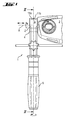
Fig. 1 als Handwerkzeugmaschine mit einem Zusatzhandgriff, -
Fig. 2 als Querschnitt in Ebene II-II ausFig. 1 -
Fig. 3 als Spannflansch -
Fig. 4 als Ausschnitt der Schlinge des Spannbandes in Perspektive - Nach den
Fig. 1 und2 weist ein Zusatzhandgriff 1, der an einem Spannflansch 2 einer nur angedeuteten Handwerkzeugmaschine 3 in Form eines Bohrhammers zur Arbeitsachse A orientiert festgelegt ist, ein zum Spannflansch 2 formschlüssig passendes Kopfteil 4 auf, in welchem ein darin geführtes schlingenförmiges Spannband 5 aus Federstahl vorhanden ist. Das Spannband 5 wird durch manuelle Drehversetzung eines Griffteils 6 verspannt, indem eine Spannschraube 7 mit einem Kopf 8 in Mitnahmeöffnungen 9 an beiden Enden 10 des Spannbandes 5 eingreift. Am Spannband 5 sind an der dem Griffteil 6 gegenüberliegenden Schlinge mehrere nach radial Innen auskragende Nocken 11a, 11 b längs versetzt ausgeformt, die formschlüssig in zugeordnete Ausnehmungen 12a, 12b am Spannflansch 2 der Handwerkzeugmaschine 3 eingreifen. Das Spannband 5 weist an den beiden Enden 10 je eine nach radial aussen abragende Führungsnase 13 auf, die beim Verspannen / Entspannen jeweils an im Wesentlichen zueinander parallelen Führungsflächen 14 des Kopfteils 4 geführt werden. - Nach
Fig. 3 und Fig. 4 haben die für die radiale Sicherung notwendigen Nocken 11a des Spannbandes 5 die Form von quer zur Schlinge länglichen Quernocken, die in Ausnehmungen 12a in Form von Längsnuten des Spannflansches 2 der Handwerkzeugmaschine 3 eingreifbar sind. Die für die axiale Sicherung notwendigen Nocken 11 b haben die Form von kreisförmigen Kugelkappennocken, die in eine Ausnehmung 12b in Form einer umlaufenden Rundnut des Spannflansches 2 eingreifbar sind.
Claims (8)
- Handwerkzeugmaschine mit einem Spannflansch (2) und mit einem daran befestigbaren Zusatzhandgriff (1), der mit seinem Kopfteil (4) zur Arbeitsachse (A) orientiert festlegbar ist, in welchem ein darin geführtes schlingenförmiges Spannband (5) vorhanden ist, das über ein Verspannmittel manuell verspannbar ist, dadurch gekennzeichnet, dass am Spannband (5) zumindest eine nach radial innen auskragende Nocke (11a, 11b) ausgeformt ist, die in eine zugeordnete Ausnehmung (12a, 12b) des Spannflansches (2) formschlüssig eingreifbar ist.
- Handwerkzeugmaschine nach Anspruch 1, dadurch gekennzeichnet, dass mehrere, längs der Schlinge des Spannbandes (5) versetzte Nocken (11a, 11 b) vorhanden sind.
- Handwerkzeugmaschine nach Anspruch 2, dadurch gekennzeichnet, dass zumindest zwei verschiedene Arten von Nocken (11a, 11 b) vorhanden sind.
- Handwerkzeugmaschine nach einem der Ansprüche 1 bis 3, dadurch gekennzeichnet, dass das Spannband (5) aus Metall besteht.
- Handwerkzeugmaschine nach einem der Ansprüche 1 bis 4, dadurch gekennzeichnet, dass das Verspannmittel ein drehversetzbares Griffteil (6) ist, das über eine Spannschraube (7) das Spannband (5) verspannt.
- Handwerkzeugmaschine nach einem der Ansprüche 1 bis 5, dadurch gekennzeichnet, dass das Spannband (5) an den beiden Enden (10) je eine Mitnahmeöffnung (9) aufweist, die einen Kopf (8) der Spannschraube (7) formschlüssig umfassen.
- Handwerkzeugmaschine nach einem der Ansprüche 1 bis 6, dadurch gekennzeichnet, dass das Spannband (5) an den beiden Enden (10) je eine nach radial Aussen abragende Führungsnase (13) aufweist.
- Handwerkzeugmaschine nach Anspruch 7, dadurch gekennzeichnet, dass das Kopfteil (4) zwei Führungsflächen (14) ausbildet, an denen die Enden (10) des Spannbandes (5) führbar sind.
Applications Claiming Priority (1)
| Application Number | Priority Date | Filing Date | Title |
|---|---|---|---|
| DE102007047881A DE102007047881A1 (de) | 2007-11-28 | 2007-11-28 | Handwerkzeugmaschine mit Zusatzhandgriff mit Spannband |
Publications (2)
| Publication Number | Publication Date |
|---|---|
| EP2065142A1 true EP2065142A1 (de) | 2009-06-03 |
| EP2065142B1 EP2065142B1 (de) | 2020-01-01 |
Family
ID=40042913
Family Applications (1)
| Application Number | Title | Priority Date | Filing Date |
|---|---|---|---|
| EP08105741.6A Active EP2065142B1 (de) | 2007-11-28 | 2008-11-06 | Handwerkzeugmaschine mit Zusatzhandgriff mit Spannband |
Country Status (5)
| Country | Link |
|---|---|
| US (1) | US20090133889A1 (de) |
| EP (1) | EP2065142B1 (de) |
| JP (1) | JP2009131952A (de) |
| CN (1) | CN101444912A (de) |
| DE (1) | DE102007047881A1 (de) |
Cited By (3)
| Publication number | Priority date | Publication date | Assignee | Title |
|---|---|---|---|---|
| WO2014118169A1 (de) * | 2013-01-31 | 2014-08-07 | Hilti Aktiengesellschaft | Abknickbare haltevorrichtung |
| EP3560661A1 (de) * | 2018-04-25 | 2019-10-30 | HILTI Aktiengesellschaft | Anordnung für eine handwerkzeugmaschine und handwerkzeugmaschine |
| EP3560660A1 (de) * | 2018-04-25 | 2019-10-30 | HILTI Aktiengesellschaft | Anordnung für eine handwekzeugmaschine und handwerkzeugmaschine |
Families Citing this family (11)
| Publication number | Priority date | Publication date | Assignee | Title |
|---|---|---|---|---|
| DE10005080C1 (de) * | 2000-02-04 | 2001-08-02 | Bosch Gmbh Robert | Handwerkzeugmaschine mit zumindest einem Handgriff und wenigstens einem elastischen, schwingungsdämpfenden Element |
| DE102009039843A1 (de) * | 2009-09-03 | 2011-03-10 | Hilti Aktiengesellschaft | Handwerkzeugmaschine mit einem Seitenhandgriff mit integrierter Zuführeinrichtung |
| JP5510733B2 (ja) * | 2010-08-16 | 2014-06-04 | 日立工機株式会社 | 手持ち式動力工具 |
| DE102011078376A1 (de) | 2011-06-30 | 2013-01-03 | Robert Bosch Gmbh | Handgriffvorrichtung, insbesondere für Handwerkzeuge |
| DE102012204457B4 (de) * | 2012-03-20 | 2016-11-17 | Metabowerke Gmbh | Mehrteiliger Zusatzhandgriff für Elektrohandwerkzeuge und Elektrohandwerkzeug |
| DE102012212803B4 (de) | 2012-07-20 | 2023-05-17 | Robert Bosch Gmbh | Handwerkzeugzusatzhandgriff |
| DE102014105842A1 (de) * | 2014-04-25 | 2015-10-29 | C. & E. Fein Gmbh | Handgeführte Werkzeugmaschine mit ergonomischem Griffteil |
| US20170252833A1 (en) * | 2016-03-04 | 2017-09-07 | Victor Martin BAYONA SALAZAR | Rigid self retracting ergonomic telescopic device, for drills that protects the user, collects wastes, fixed measurement drilling, increases the contact area, allow the total viewing and if it's necessary dosing lubrication; and its assembly process |
| USD867836S1 (en) | 2018-01-10 | 2019-11-26 | Rafael Juarez | Gardening tool |
| WO2022204118A1 (en) | 2021-03-25 | 2022-09-29 | Milwaukee Electric Tool Corporation | Side handle for power tool |
| US11951606B1 (en) * | 2022-10-14 | 2024-04-09 | Snap-On Incorporated | Handle and tool with integrated handle mount |
Citations (11)
| Publication number | Priority date | Publication date | Assignee | Title |
|---|---|---|---|---|
| US4276675A (en) * | 1980-02-07 | 1981-07-07 | Black & Decker Inc. | Auxiliary handle for a power tool |
| EP0132593A2 (de) | 1983-06-25 | 1985-02-13 | C. & E. FEIN GmbH & Co. | Zusatzhandgriff für handgeführte Werkzeuge |
| CH661241A5 (en) * | 1982-09-08 | 1987-07-15 | Bosch Gmbh Robert | Auxiliary handle for a powered hand tool |
| EP0249037A2 (de) * | 1986-06-10 | 1987-12-16 | Scintilla Ag | Zusatzhandgriff für Handbohrmaschinen |
| FR2620369A1 (fr) * | 1987-09-16 | 1989-03-17 | Hilti Ag | Poignee additionnelle pour perceuses |
| DE3829801A1 (de) * | 1988-09-02 | 1990-03-15 | Metabowerke Kg | Zusatzhandgriff |
| DE4406718A1 (de) * | 1994-02-25 | 1995-08-31 | Black & Decker Inc | Zusatzhandgriff für handgeführte Werkzeuge |
| DE102005057269A1 (de) | 2005-09-08 | 2007-03-15 | Robert Bosch Gmbh | Befestigungsvorrichtung sowie Elektrowerkzeugmaschine |
| DE202006020017U1 (de) * | 2006-09-01 | 2007-07-26 | Robert Bosch Gmbh | Zusatzhandgriffvorrichtung |
| EP1832397A1 (de) * | 2006-03-09 | 2007-09-12 | Black & Decker, Inc. | Zusatzhandgriff für eine Stichsäge |
| US20070212991A1 (en) * | 2006-03-10 | 2007-09-13 | Assan Izmailov | Adjustable handheld tool |
Family Cites Families (10)
| Publication number | Priority date | Publication date | Assignee | Title |
|---|---|---|---|---|
| US1083054A (en) * | 1913-01-22 | 1913-12-30 | Leo Brown | Supplementary shovel-handle. |
| DE2705410C2 (de) * | 1977-02-09 | 1985-06-13 | Robert Bosch Gmbh, 7000 Stuttgart | Vorrichtung zum Absaugen von Bohrklein an einer Handwerkzeugmaschine |
| JPS6161111U (de) * | 1984-09-25 | 1986-04-24 | ||
| JPH01135484A (ja) * | 1987-11-14 | 1989-05-29 | Matsushita Electric Works Ltd | 電動工具の補助ハンドル |
| DE19854468A1 (de) * | 1998-11-25 | 2000-06-08 | Flex Elektrowerkzeuge Gmbh | Handwerkzeugmaschine |
| DE10106050B4 (de) * | 2001-02-09 | 2017-02-16 | Hilti Aktiengesellschaft | Handwerkzeugmaschine mit einem Zusatzhandgriff |
| DE10130548B4 (de) * | 2001-06-25 | 2008-01-03 | Robert Bosch Gmbh | Zusatzhandgriff |
| US6595300B2 (en) * | 2001-12-20 | 2003-07-22 | Black & Decker Inc. | Side handles on drill/drivers |
| DE102004061522A1 (de) * | 2004-12-21 | 2006-06-29 | Hilti Ag | Seitenhandgriff |
| USD572563S1 (en) * | 2006-03-09 | 2008-07-08 | Black & Decker Inc. | Auxiliary handle for a reciprocating saw |
-
2007
- 2007-11-28 DE DE102007047881A patent/DE102007047881A1/de not_active Withdrawn
-
2008
- 2008-11-06 EP EP08105741.6A patent/EP2065142B1/de active Active
- 2008-11-10 US US12/291,525 patent/US20090133889A1/en not_active Abandoned
- 2008-11-25 CN CNA2008101763673A patent/CN101444912A/zh active Pending
- 2008-11-26 JP JP2008301162A patent/JP2009131952A/ja active Pending
Patent Citations (11)
| Publication number | Priority date | Publication date | Assignee | Title |
|---|---|---|---|---|
| US4276675A (en) * | 1980-02-07 | 1981-07-07 | Black & Decker Inc. | Auxiliary handle for a power tool |
| CH661241A5 (en) * | 1982-09-08 | 1987-07-15 | Bosch Gmbh Robert | Auxiliary handle for a powered hand tool |
| EP0132593A2 (de) | 1983-06-25 | 1985-02-13 | C. & E. FEIN GmbH & Co. | Zusatzhandgriff für handgeführte Werkzeuge |
| EP0249037A2 (de) * | 1986-06-10 | 1987-12-16 | Scintilla Ag | Zusatzhandgriff für Handbohrmaschinen |
| FR2620369A1 (fr) * | 1987-09-16 | 1989-03-17 | Hilti Ag | Poignee additionnelle pour perceuses |
| DE3829801A1 (de) * | 1988-09-02 | 1990-03-15 | Metabowerke Kg | Zusatzhandgriff |
| DE4406718A1 (de) * | 1994-02-25 | 1995-08-31 | Black & Decker Inc | Zusatzhandgriff für handgeführte Werkzeuge |
| DE102005057269A1 (de) | 2005-09-08 | 2007-03-15 | Robert Bosch Gmbh | Befestigungsvorrichtung sowie Elektrowerkzeugmaschine |
| EP1832397A1 (de) * | 2006-03-09 | 2007-09-12 | Black & Decker, Inc. | Zusatzhandgriff für eine Stichsäge |
| US20070212991A1 (en) * | 2006-03-10 | 2007-09-13 | Assan Izmailov | Adjustable handheld tool |
| DE202006020017U1 (de) * | 2006-09-01 | 2007-07-26 | Robert Bosch Gmbh | Zusatzhandgriffvorrichtung |
Cited By (7)
| Publication number | Priority date | Publication date | Assignee | Title |
|---|---|---|---|---|
| WO2014118169A1 (de) * | 2013-01-31 | 2014-08-07 | Hilti Aktiengesellschaft | Abknickbare haltevorrichtung |
| US9498876B2 (en) | 2013-01-31 | 2016-11-22 | Hilti Aktiengesellschaft | Collapsible holding arrangement |
| EP3560661A1 (de) * | 2018-04-25 | 2019-10-30 | HILTI Aktiengesellschaft | Anordnung für eine handwerkzeugmaschine und handwerkzeugmaschine |
| EP3560660A1 (de) * | 2018-04-25 | 2019-10-30 | HILTI Aktiengesellschaft | Anordnung für eine handwekzeugmaschine und handwerkzeugmaschine |
| WO2019206720A1 (de) * | 2018-04-25 | 2019-10-31 | Hilti Aktiengesellschaft | Anordnung für eine handwerkzeugmaschine und handwerkzeugmaschine |
| WO2019206762A1 (de) * | 2018-04-25 | 2019-10-31 | Hilti Aktiengesellschaft | Anordnung für eine handwerkzeugmaschine und handwerkzeugmaschine |
| US11931877B2 (en) | 2018-04-25 | 2024-03-19 | Hilti Aktiengesellschaft | Arrangement for a hand-held power tool, and hand-held power tool |
Also Published As
| Publication number | Publication date |
|---|---|
| US20090133889A1 (en) | 2009-05-28 |
| DE102007047881A1 (de) | 2009-06-04 |
| EP2065142B1 (de) | 2020-01-01 |
| CN101444912A (zh) | 2009-06-03 |
| JP2009131952A (ja) | 2009-06-18 |
Similar Documents
| Publication | Publication Date | Title |
|---|---|---|
| EP2065142A1 (de) | Handwerkzeugmaschine mit Zusatzhandgriff mit Spannband | |
| DE102007009943B3 (de) | Hubsäge, insbesondere Stichsäge | |
| DE102012212803B4 (de) | Handwerkzeugzusatzhandgriff | |
| DE102007041840A1 (de) | Handwerkzeugmaschine mit Schutzhaube, insbesondere Winkelschleifer | |
| DE102008042113A1 (de) | Zusatzhandgriff für eine Handwerkzeugmaschine | |
| WO2009109247A1 (de) | Zusatzhandgriff sowie handwerkzeugmaschine | |
| WO2001049465A1 (de) | Kettensäge und kettenspannvorrichtung dafür | |
| DE10006042A1 (de) | Handwerkzeugmaschine mit Tiefenanschlag | |
| DE10034437A1 (de) | Handgeführtes Arbeitsgerät | |
| DE10316182A1 (de) | Handschleifmaschine mit Schutzhaube | |
| EP1452284B1 (de) | Schnellspannmutter für scheibenförmige Werkzeuge | |
| WO2009153084A1 (de) | Werkzeugmaschine, insbesondere handwerkzeugmaschine | |
| EP1396302B1 (de) | Handwerkzeugmaschine mit Befestigungmittel für einen Tiefenanschlag | |
| DE102008000158A1 (de) | Handgriff für ein insbesondere motorisch angetriebenes Werkzeug | |
| DE602006000263T2 (de) | Werkzeugspannfutter für eine drehende Maschine | |
| DE501598C (de) | Schlagwerkzeug mit einer auf dem Vorderende des Zylinders aufschraubbaren Haltefeder fuer den Arbeitsstahl | |
| DE102005036642B3 (de) | Vorrichtung zum Befestigen eines Vorsatzgerätes an einer Handwerkzeugmaschine | |
| DE3921752A1 (de) | Handgeraet mit trenn- oder schleifscheibe | |
| DE202011000143U1 (de) | Motorarbeitsgerät mit einer Spanneinrichtung für einen Riemen | |
| DE202009001797U1 (de) | Werkzeughalterung für Elektrohandwerkzeuggeräte | |
| WO2009074410A1 (de) | Handgriff | |
| DE102006052051A1 (de) | Werkzeughalter | |
| EP1300217B1 (de) | Bohrständer mit fixierbarer Fussplatte | |
| EP1840049B1 (de) | Greifelement für eine Gasflasche | |
| DE102005057368A1 (de) | In eine handführbare Bohrmaschine einsetzbare Kupplung |
Legal Events
| Date | Code | Title | Description |
|---|---|---|---|
| PUAI | Public reference made under article 153(3) epc to a published international application that has entered the european phase |
Free format text: ORIGINAL CODE: 0009012 |
|
| AK | Designated contracting states |
Kind code of ref document: A1 Designated state(s): AT BE BG CH CY CZ DE DK EE ES FI FR GB GR HR HU IE IS IT LI LT LU LV MC MT NL NO PL PT RO SE SI SK TR |
|
| AX | Request for extension of the european patent |
Extension state: AL BA MK RS |
|
| 17P | Request for examination filed |
Effective date: 20091203 |
|
| AKX | Designation fees paid |
Designated state(s): AT BE BG CH CY CZ DE DK EE ES FI FR GB GR HR HU IE IS IT LI LT LU LV MC MT NL NO PL PT RO SE SI SK TR |
|
| 17Q | First examination report despatched |
Effective date: 20100316 |
|
| STAA | Information on the status of an ep patent application or granted ep patent |
Free format text: STATUS: EXAMINATION IS IN PROGRESS |
|
| GRAP | Despatch of communication of intention to grant a patent |
Free format text: ORIGINAL CODE: EPIDOSNIGR1 |
|
| STAA | Information on the status of an ep patent application or granted ep patent |
Free format text: STATUS: GRANT OF PATENT IS INTENDED |
|
| INTG | Intention to grant announced |
Effective date: 20190910 |
|
| RIN1 | Information on inventor provided before grant (corrected) |
Inventor name: LUDWIG, MANFRED Inventor name: HOFBRUCKER, THOMAS Inventor name: KELLER, VALENTIN Inventor name: SCHILLING, PASCAL |
|
| GRAS | Grant fee paid |
Free format text: ORIGINAL CODE: EPIDOSNIGR3 |
|
| GRAA | (expected) grant |
Free format text: ORIGINAL CODE: 0009210 |
|
| STAA | Information on the status of an ep patent application or granted ep patent |
Free format text: STATUS: THE PATENT HAS BEEN GRANTED |
|
| AK | Designated contracting states |
Kind code of ref document: B1 Designated state(s): AT BE BG CH CY CZ DE DK EE ES FI FR GB GR HR HU IE IS IT LI LT LU LV MC MT NL NO PL PT RO SE SI SK TR |
|
| REG | Reference to a national code |
Ref country code: GB Ref legal event code: FG4D Free format text: NOT ENGLISH |
|
| REG | Reference to a national code |
Ref country code: AT Ref legal event code: REF Ref document number: 1219193 Country of ref document: AT Kind code of ref document: T Effective date: 20200115 Ref country code: CH Ref legal event code: EP |
|
| REG | Reference to a national code |
Ref country code: IE Ref legal event code: FG4D Free format text: LANGUAGE OF EP DOCUMENT: GERMAN |
|
| REG | Reference to a national code |
Ref country code: DE Ref legal event code: R096 Ref document number: 502008016996 Country of ref document: DE |
|
| REG | Reference to a national code |
Ref country code: NL Ref legal event code: MP Effective date: 20200101 |
|
| REG | Reference to a national code |
Ref country code: LT Ref legal event code: MG4D |
|
| PG25 | Lapsed in a contracting state [announced via postgrant information from national office to epo] |
Ref country code: NL Free format text: LAPSE BECAUSE OF FAILURE TO SUBMIT A TRANSLATION OF THE DESCRIPTION OR TO PAY THE FEE WITHIN THE PRESCRIBED TIME-LIMIT Effective date: 20200101 Ref country code: FI Free format text: LAPSE BECAUSE OF FAILURE TO SUBMIT A TRANSLATION OF THE DESCRIPTION OR TO PAY THE FEE WITHIN THE PRESCRIBED TIME-LIMIT Effective date: 20200101 Ref country code: LT Free format text: LAPSE BECAUSE OF FAILURE TO SUBMIT A TRANSLATION OF THE DESCRIPTION OR TO PAY THE FEE WITHIN THE PRESCRIBED TIME-LIMIT Effective date: 20200101 Ref country code: CZ Free format text: LAPSE BECAUSE OF FAILURE TO SUBMIT A TRANSLATION OF THE DESCRIPTION OR TO PAY THE FEE WITHIN THE PRESCRIBED TIME-LIMIT Effective date: 20200101 Ref country code: PT Free format text: LAPSE BECAUSE OF FAILURE TO SUBMIT A TRANSLATION OF THE DESCRIPTION OR TO PAY THE FEE WITHIN THE PRESCRIBED TIME-LIMIT Effective date: 20200527 Ref country code: NO Free format text: LAPSE BECAUSE OF FAILURE TO SUBMIT A TRANSLATION OF THE DESCRIPTION OR TO PAY THE FEE WITHIN THE PRESCRIBED TIME-LIMIT Effective date: 20200401 |
|
| PG25 | Lapsed in a contracting state [announced via postgrant information from national office to epo] |
Ref country code: GR Free format text: LAPSE BECAUSE OF FAILURE TO SUBMIT A TRANSLATION OF THE DESCRIPTION OR TO PAY THE FEE WITHIN THE PRESCRIBED TIME-LIMIT Effective date: 20200402 Ref country code: HR Free format text: LAPSE BECAUSE OF FAILURE TO SUBMIT A TRANSLATION OF THE DESCRIPTION OR TO PAY THE FEE WITHIN THE PRESCRIBED TIME-LIMIT Effective date: 20200101 Ref country code: SE Free format text: LAPSE BECAUSE OF FAILURE TO SUBMIT A TRANSLATION OF THE DESCRIPTION OR TO PAY THE FEE WITHIN THE PRESCRIBED TIME-LIMIT Effective date: 20200101 Ref country code: LV Free format text: LAPSE BECAUSE OF FAILURE TO SUBMIT A TRANSLATION OF THE DESCRIPTION OR TO PAY THE FEE WITHIN THE PRESCRIBED TIME-LIMIT Effective date: 20200101 Ref country code: IS Free format text: LAPSE BECAUSE OF FAILURE TO SUBMIT A TRANSLATION OF THE DESCRIPTION OR TO PAY THE FEE WITHIN THE PRESCRIBED TIME-LIMIT Effective date: 20200501 Ref country code: BG Free format text: LAPSE BECAUSE OF FAILURE TO SUBMIT A TRANSLATION OF THE DESCRIPTION OR TO PAY THE FEE WITHIN THE PRESCRIBED TIME-LIMIT Effective date: 20200401 |
|
| REG | Reference to a national code |
Ref country code: DE Ref legal event code: R097 Ref document number: 502008016996 Country of ref document: DE |
|
| PG25 | Lapsed in a contracting state [announced via postgrant information from national office to epo] |
Ref country code: DK Free format text: LAPSE BECAUSE OF FAILURE TO SUBMIT A TRANSLATION OF THE DESCRIPTION OR TO PAY THE FEE WITHIN THE PRESCRIBED TIME-LIMIT Effective date: 20200101 Ref country code: SK Free format text: LAPSE BECAUSE OF FAILURE TO SUBMIT A TRANSLATION OF THE DESCRIPTION OR TO PAY THE FEE WITHIN THE PRESCRIBED TIME-LIMIT Effective date: 20200101 Ref country code: EE Free format text: LAPSE BECAUSE OF FAILURE TO SUBMIT A TRANSLATION OF THE DESCRIPTION OR TO PAY THE FEE WITHIN THE PRESCRIBED TIME-LIMIT Effective date: 20200101 Ref country code: ES Free format text: LAPSE BECAUSE OF FAILURE TO SUBMIT A TRANSLATION OF THE DESCRIPTION OR TO PAY THE FEE WITHIN THE PRESCRIBED TIME-LIMIT Effective date: 20200101 Ref country code: RO Free format text: LAPSE BECAUSE OF FAILURE TO SUBMIT A TRANSLATION OF THE DESCRIPTION OR TO PAY THE FEE WITHIN THE PRESCRIBED TIME-LIMIT Effective date: 20200101 |
|
| PLBE | No opposition filed within time limit |
Free format text: ORIGINAL CODE: 0009261 |
|
| STAA | Information on the status of an ep patent application or granted ep patent |
Free format text: STATUS: NO OPPOSITION FILED WITHIN TIME LIMIT |
|
| 26N | No opposition filed |
Effective date: 20201002 |
|
| PG25 | Lapsed in a contracting state [announced via postgrant information from national office to epo] |
Ref country code: IT Free format text: LAPSE BECAUSE OF FAILURE TO SUBMIT A TRANSLATION OF THE DESCRIPTION OR TO PAY THE FEE WITHIN THE PRESCRIBED TIME-LIMIT Effective date: 20200101 |
|
| PGFP | Annual fee paid to national office [announced via postgrant information from national office to epo] |
Ref country code: GB Payment date: 20201120 Year of fee payment: 13 |
|
| PG25 | Lapsed in a contracting state [announced via postgrant information from national office to epo] |
Ref country code: SI Free format text: LAPSE BECAUSE OF FAILURE TO SUBMIT A TRANSLATION OF THE DESCRIPTION OR TO PAY THE FEE WITHIN THE PRESCRIBED TIME-LIMIT Effective date: 20200101 Ref country code: PL Free format text: LAPSE BECAUSE OF FAILURE TO SUBMIT A TRANSLATION OF THE DESCRIPTION OR TO PAY THE FEE WITHIN THE PRESCRIBED TIME-LIMIT Effective date: 20200101 |
|
| PG25 | Lapsed in a contracting state [announced via postgrant information from national office to epo] |
Ref country code: MC Free format text: LAPSE BECAUSE OF FAILURE TO SUBMIT A TRANSLATION OF THE DESCRIPTION OR TO PAY THE FEE WITHIN THE PRESCRIBED TIME-LIMIT Effective date: 20200101 |
|
| REG | Reference to a national code |
Ref country code: CH Ref legal event code: PL |
|
| PG25 | Lapsed in a contracting state [announced via postgrant information from national office to epo] |
Ref country code: LU Free format text: LAPSE BECAUSE OF NON-PAYMENT OF DUE FEES Effective date: 20201106 |
|
| REG | Reference to a national code |
Ref country code: BE Ref legal event code: MM Effective date: 20201130 |
|
| PG25 | Lapsed in a contracting state [announced via postgrant information from national office to epo] |
Ref country code: LI Free format text: LAPSE BECAUSE OF NON-PAYMENT OF DUE FEES Effective date: 20201130 Ref country code: CH Free format text: LAPSE BECAUSE OF NON-PAYMENT OF DUE FEES Effective date: 20201130 |
|
| PG25 | Lapsed in a contracting state [announced via postgrant information from national office to epo] |
Ref country code: FR Free format text: LAPSE BECAUSE OF NON-PAYMENT OF DUE FEES Effective date: 20201130 Ref country code: IE Free format text: LAPSE BECAUSE OF NON-PAYMENT OF DUE FEES Effective date: 20201106 |
|
| REG | Reference to a national code |
Ref country code: AT Ref legal event code: MM01 Ref document number: 1219193 Country of ref document: AT Kind code of ref document: T Effective date: 20201106 |
|
| PG25 | Lapsed in a contracting state [announced via postgrant information from national office to epo] |
Ref country code: AT Free format text: LAPSE BECAUSE OF NON-PAYMENT OF DUE FEES Effective date: 20201106 |
|
| PG25 | Lapsed in a contracting state [announced via postgrant information from national office to epo] |
Ref country code: TR Free format text: LAPSE BECAUSE OF FAILURE TO SUBMIT A TRANSLATION OF THE DESCRIPTION OR TO PAY THE FEE WITHIN THE PRESCRIBED TIME-LIMIT Effective date: 20200101 Ref country code: MT Free format text: LAPSE BECAUSE OF FAILURE TO SUBMIT A TRANSLATION OF THE DESCRIPTION OR TO PAY THE FEE WITHIN THE PRESCRIBED TIME-LIMIT Effective date: 20200101 Ref country code: CY Free format text: LAPSE BECAUSE OF FAILURE TO SUBMIT A TRANSLATION OF THE DESCRIPTION OR TO PAY THE FEE WITHIN THE PRESCRIBED TIME-LIMIT Effective date: 20200101 |
|
| GBPC | Gb: european patent ceased through non-payment of renewal fee |
Effective date: 20211106 |
|
| PG25 | Lapsed in a contracting state [announced via postgrant information from national office to epo] |
Ref country code: BE Free format text: LAPSE BECAUSE OF NON-PAYMENT OF DUE FEES Effective date: 20201130 |
|
| PG25 | Lapsed in a contracting state [announced via postgrant information from national office to epo] |
Ref country code: GB Free format text: LAPSE BECAUSE OF NON-PAYMENT OF DUE FEES Effective date: 20211106 |
|
| PGFP | Annual fee paid to national office [announced via postgrant information from national office to epo] |
Ref country code: DE Payment date: 20231121 Year of fee payment: 16 |