EP2058727B1 - Mobiles endgerat mit beruhrungsempfindlicher flache und beruhrungsempfindlichem bildschirm - Google Patents
Mobiles endgerat mit beruhrungsempfindlicher flache und beruhrungsempfindlichem bildschirm Download PDFInfo
- Publication number
- EP2058727B1 EP2058727B1 EP08163667.2A EP08163667A EP2058727B1 EP 2058727 B1 EP2058727 B1 EP 2058727B1 EP 08163667 A EP08163667 A EP 08163667A EP 2058727 B1 EP2058727 B1 EP 2058727B1
- Authority
- EP
- European Patent Office
- Prior art keywords
- mobile terminal
- touch
- window
- region
- key
- Prior art date
- Legal status (The legal status is an assumption and is not a legal conclusion. Google has not performed a legal analysis and makes no representation as to the accuracy of the status listed.)
- Active
Links
Images


Classifications
-
- G—PHYSICS
- G06—COMPUTING OR CALCULATING; COUNTING
- G06F—ELECTRIC DIGITAL DATA PROCESSING
- G06F3/00—Input arrangements for transferring data to be processed into a form capable of being handled by the computer; Output arrangements for transferring data from processing unit to output unit, e.g. interface arrangements
- G06F3/01—Input arrangements or combined input and output arrangements for interaction between user and computer
- G06F3/03—Arrangements for converting the position or the displacement of a member into a coded form
- G06F3/041—Digitisers, e.g. for touch screens or touch pads, characterised by the transducing means
- G06F3/044—Digitisers, e.g. for touch screens or touch pads, characterised by the transducing means by capacitive means
- G06F3/0443—Digitisers, e.g. for touch screens or touch pads, characterised by the transducing means by capacitive means using a single layer of sensing electrodes
-
- G—PHYSICS
- G06—COMPUTING OR CALCULATING; COUNTING
- G06F—ELECTRIC DIGITAL DATA PROCESSING
- G06F1/00—Details not covered by groups G06F3/00 - G06F13/00 and G06F21/00
- G06F1/16—Constructional details or arrangements
- G06F1/1613—Constructional details or arrangements for portable computers
- G06F1/1615—Constructional details or arrangements for portable computers with several enclosures having relative motions, each enclosure supporting at least one I/O or computing function
- G06F1/1624—Constructional details or arrangements for portable computers with several enclosures having relative motions, each enclosure supporting at least one I/O or computing function with sliding enclosures, e.g. sliding keyboard or display
-
- G—PHYSICS
- G06—COMPUTING OR CALCULATING; COUNTING
- G06F—ELECTRIC DIGITAL DATA PROCESSING
- G06F1/00—Details not covered by groups G06F3/00 - G06F13/00 and G06F21/00
- G06F1/16—Constructional details or arrangements
- G06F1/1613—Constructional details or arrangements for portable computers
- G06F1/1633—Constructional details or arrangements of portable computers not specific to the type of enclosures covered by groups G06F1/1615 - G06F1/1626
- G06F1/1656—Details related to functional adaptations of the enclosure, e.g. to provide protection against EMI, shock, water, or to host detachable peripherals like a mouse or removable expansions units like PCMCIA cards, or to provide access to internal components for maintenance or to removable storage supports like CDs or DVDs, or to mechanically mount accessories
-
- G—PHYSICS
- G06—COMPUTING OR CALCULATING; COUNTING
- G06F—ELECTRIC DIGITAL DATA PROCESSING
- G06F1/00—Details not covered by groups G06F3/00 - G06F13/00 and G06F21/00
- G06F1/16—Constructional details or arrangements
- G06F1/1613—Constructional details or arrangements for portable computers
- G06F1/1633—Constructional details or arrangements of portable computers not specific to the type of enclosures covered by groups G06F1/1615 - G06F1/1626
- G06F1/1684—Constructional details or arrangements related to integrated I/O peripherals not covered by groups G06F1/1635 - G06F1/1675
- G06F1/1686—Constructional details or arrangements related to integrated I/O peripherals not covered by groups G06F1/1635 - G06F1/1675 the I/O peripheral being an integrated camera
-
- G—PHYSICS
- G06—COMPUTING OR CALCULATING; COUNTING
- G06F—ELECTRIC DIGITAL DATA PROCESSING
- G06F1/00—Details not covered by groups G06F3/00 - G06F13/00 and G06F21/00
- G06F1/16—Constructional details or arrangements
- G06F1/1613—Constructional details or arrangements for portable computers
- G06F1/1633—Constructional details or arrangements of portable computers not specific to the type of enclosures covered by groups G06F1/1615 - G06F1/1626
- G06F1/1684—Constructional details or arrangements related to integrated I/O peripherals not covered by groups G06F1/1635 - G06F1/1675
- G06F1/169—Constructional details or arrangements related to integrated I/O peripherals not covered by groups G06F1/1635 - G06F1/1675 the I/O peripheral being an integrated pointing device, e.g. trackball in the palm rest area, mini-joystick integrated between keyboard keys, touch pads or touch stripes
-
- G—PHYSICS
- G06—COMPUTING OR CALCULATING; COUNTING
- G06F—ELECTRIC DIGITAL DATA PROCESSING
- G06F3/00—Input arrangements for transferring data to be processed into a form capable of being handled by the computer; Output arrangements for transferring data from processing unit to output unit, e.g. interface arrangements
- G06F3/01—Input arrangements or combined input and output arrangements for interaction between user and computer
- G06F3/03—Arrangements for converting the position or the displacement of a member into a coded form
- G06F3/041—Digitisers, e.g. for touch screens or touch pads, characterised by the transducing means
- G06F3/044—Digitisers, e.g. for touch screens or touch pads, characterised by the transducing means by capacitive means
- G06F3/0445—Digitisers, e.g. for touch screens or touch pads, characterised by the transducing means by capacitive means using two or more layers of sensing electrodes, e.g. using two layers of electrodes separated by a dielectric layer
-
- G—PHYSICS
- G06—COMPUTING OR CALCULATING; COUNTING
- G06F—ELECTRIC DIGITAL DATA PROCESSING
- G06F3/00—Input arrangements for transferring data to be processed into a form capable of being handled by the computer; Output arrangements for transferring data from processing unit to output unit, e.g. interface arrangements
- G06F3/01—Input arrangements or combined input and output arrangements for interaction between user and computer
- G06F3/03—Arrangements for converting the position or the displacement of a member into a coded form
- G06F3/041—Digitisers, e.g. for touch screens or touch pads, characterised by the transducing means
- G06F3/045—Digitisers, e.g. for touch screens or touch pads, characterised by the transducing means using resistive elements, e.g. a single continuous surface or two parallel surfaces put in contact
-
- G—PHYSICS
- G06—COMPUTING OR CALCULATING; COUNTING
- G06F—ELECTRIC DIGITAL DATA PROCESSING
- G06F3/00—Input arrangements for transferring data to be processed into a form capable of being handled by the computer; Output arrangements for transferring data from processing unit to output unit, e.g. interface arrangements
- G06F3/01—Input arrangements or combined input and output arrangements for interaction between user and computer
- G06F3/048—Interaction techniques based on graphical user interfaces [GUI]
- G06F3/0487—Interaction techniques based on graphical user interfaces [GUI] using specific features provided by the input device, e.g. functions controlled by the rotation of a mouse with dual sensing arrangements, or of the nature of the input device, e.g. tap gestures based on pressure sensed by a digitiser
- G06F3/0488—Interaction techniques based on graphical user interfaces [GUI] using specific features provided by the input device, e.g. functions controlled by the rotation of a mouse with dual sensing arrangements, or of the nature of the input device, e.g. tap gestures based on pressure sensed by a digitiser using a touch-screen or digitiser, e.g. input of commands through traced gestures
- G06F3/04883—Interaction techniques based on graphical user interfaces [GUI] using specific features provided by the input device, e.g. functions controlled by the rotation of a mouse with dual sensing arrangements, or of the nature of the input device, e.g. tap gestures based on pressure sensed by a digitiser using a touch-screen or digitiser, e.g. input of commands through traced gestures for inputting data by handwriting, e.g. gesture or text
-
- G—PHYSICS
- G06—COMPUTING OR CALCULATING; COUNTING
- G06F—ELECTRIC DIGITAL DATA PROCESSING
- G06F3/00—Input arrangements for transferring data to be processed into a form capable of being handled by the computer; Output arrangements for transferring data from processing unit to output unit, e.g. interface arrangements
- G06F3/01—Input arrangements or combined input and output arrangements for interaction between user and computer
- G06F3/048—Interaction techniques based on graphical user interfaces [GUI]
- G06F3/0487—Interaction techniques based on graphical user interfaces [GUI] using specific features provided by the input device, e.g. functions controlled by the rotation of a mouse with dual sensing arrangements, or of the nature of the input device, e.g. tap gestures based on pressure sensed by a digitiser
- G06F3/0488—Interaction techniques based on graphical user interfaces [GUI] using specific features provided by the input device, e.g. functions controlled by the rotation of a mouse with dual sensing arrangements, or of the nature of the input device, e.g. tap gestures based on pressure sensed by a digitiser using a touch-screen or digitiser, e.g. input of commands through traced gestures
- G06F3/04886—Interaction techniques based on graphical user interfaces [GUI] using specific features provided by the input device, e.g. functions controlled by the rotation of a mouse with dual sensing arrangements, or of the nature of the input device, e.g. tap gestures based on pressure sensed by a digitiser using a touch-screen or digitiser, e.g. input of commands through traced gestures by partitioning the display area of the touch-screen or the surface of the digitising tablet into independently controllable areas, e.g. virtual keyboards or menus
-
- H—ELECTRICITY
- H04—ELECTRIC COMMUNICATION TECHNIQUE
- H04M—TELEPHONIC COMMUNICATION
- H04M1/00—Substation equipment, e.g. for use by subscribers
- H04M1/02—Constructional features of telephone sets
- H04M1/0202—Portable telephone sets, e.g. cordless phones, mobile phones or bar type handsets
- H04M1/0206—Portable telephones comprising a plurality of mechanically joined movable body parts, e.g. hinged housings
- H04M1/0208—Portable telephones comprising a plurality of mechanically joined movable body parts, e.g. hinged housings characterized by the relative motions of the body parts
- H04M1/0235—Slidable or telescopic telephones, i.e. with a relative translation movement of the body parts; Telephones using a combination of translation and other relative motions of the body parts
- H04M1/0237—Sliding mechanism with one degree of freedom
-
- H—ELECTRICITY
- H04—ELECTRIC COMMUNICATION TECHNIQUE
- H04M—TELEPHONIC COMMUNICATION
- H04M1/00—Substation equipment, e.g. for use by subscribers
- H04M1/02—Constructional features of telephone sets
- H04M1/0202—Portable telephone sets, e.g. cordless phones, mobile phones or bar type handsets
- H04M1/026—Details of the structure or mounting of specific components
- H04M1/0266—Details of the structure or mounting of specific components for a display module assembly
-
- H—ELECTRICITY
- H04—ELECTRIC COMMUNICATION TECHNIQUE
- H04M—TELEPHONIC COMMUNICATION
- H04M2250/00—Details of telephonic subscriber devices
- H04M2250/22—Details of telephonic subscriber devices including a touch pad, a touch sensor or a touch detector
Definitions
- the present invention relates to a mobile terminal including a touch screen part and a touch key part on a front surface of the mobile terminal.
- Mobile terminals now provide many additional services besides the basic call service. For example, users can now access the Internet, watch videos and movies, listen to music, take pictures, perform scheduling tasks, etc. using their mobile terminal. Because the mobile terminal is mobile and lightweight, the user can easily carry their mobile terminals with them.
- some mobile terminals also include a touch screen that the user can touch to select particular items or menu options.
- the options or other items displayed on the touch screen For example, the user's input on the touch screen is not recognized or the user touches two or more menu options or items displayed on the terminal.
- the user often has to read a user's manual to learn how to operate the mobile terminal, because there are a large variety of options provided with the mobile terminal.
- XP007901882 " Handbook for the Palm Zire 71 Handheld", 2003 , discloses a terminal device with a touch sensitive input device having two distinct regions for input.
- one object of the present invention is to address the above-noted and other problems.
- Another object of the present invention is to provide a user interface environment that is easy to use and to provide a mobile terminal that has a simple design.
- the present invention provides in one aspect a mobile terminal according to claim 1.
- FIG. 1 is a front perspective view of a mobile terminal 100 according to an embodiment of the present invention.
- the mobile terminal 100 includes a first body 110 and a second body 120 that is slidably moved along at least one direction with respect to the first body 110.
- the mobile terminal 100 is in a closed configuration.
- the first terminal body 110 is slid forward as shown in FIG. 1 , the first body 110 exposes at least a portion of the second terminal body 120 and is an open configuration.
- the mobile terminal 100 is usually in a standby mode in the closed configuration, but the standby mode can be released by user manipulation.
- the mobile terminal 100 mainly functions in a call mode or the like, but the user can also change this mode by manipulating a particular menu option or key.
- the mobile terminal 100 can also be automatically placed in the standby mode after the lapse of a certain time.
- the case (housing, casing, cover, etc.) forming the external appearance of the first terminal body 110 includes a front case 111 and a rear case 112.
- Various electronic components are also installed in a space formed by the front case 111 and the case 112.
- one or more intermediate cases may also be additionally disposed between the front case 111 and the rear case 112.
- the case may also be formed by injection-molding a synthetic resin, or may be made of a metallic material such as stainless steel (STS), titanium (Ti), or the like.
- the first body 110 includes a touch screen part 113, a touch key pad part 114, an audio output unit 115, a first image input unit 116, and a first manipulating unit 117 on its front surface.
- the front surface of the front case 11 includes a first region 113a and a second region 114a, and the touch screen part 113 and the touch keypad part 114 are respectively formed on the first and second regions 113a and 114a.
- the touch screen part 113 is configured to display visual information and input information in a tactile manner
- the touch keypad part 114 is configured to input information by a touch applied to a particular position set on the second region.
- the audio output unit 115 may be a receiver or a speaker
- the first image input unit 116 may be a camera module for capturing an image or video.
- the first manipulating unit 117 includes menu options that the user may select by pressing the corresponding menu option to thereby perform different functions on the terminal 100.
- the second body 120 includes a front case 121 and a rear case 122 that forms the second body 120.
- the second body 120 also includes a second manipulation unit 123 (e.g., keypad, etc.).
- a third manipulating unit 124, an audio input unit 125, and an interface 126 are also disposed on at least one of the front case 121 and the rear case 122.
- the second and third manipulating units 123 and 124 are configured to allow a user to perform a particular option on the terminal 100.
- the second and third manipulating units 123 and 124 may be implemented as a dome switch or a touch pad that receives a command or information according to a push or touch manipulation by the user, or may be implemented as a wheel for rotating a key, a jog type, a joystick, or the like.
- the first manipulation unit 117 is used by the user to input a command such as start, end, scroll, etc.
- the second manipulating unit 123 is used to input numbers, characters, symbols, etc.
- the third manipulating unit 124 may operate as a hot key for performing a particular function such as activation of the first image input unit 116.
- the audio input unit 125 may be implemented in the form of, for example, a microphone to receive the user's voice or other sounds.
- the interface 126 is configured to allow the mobile terminal 100 to exchange data with an external device.
- the interface 126 may be implemented as one of a connection port (terminal) for connecting an ear phone to the mobile terminal via a fixed or wireless method, a port (e.g., an IrDA port), a BLUETOOTH TM port, a wireless LAN port, or a power supply port that supplies power to the mobile terminal 100, or the like.
- the interface 126 may also be a card socket (or receiving unit) for accommodating an external card, such as a Subscriber Identity Module (SIM), a User Identity Module (UIM), a memory card for storing information, or the like.
- SIM Subscriber Identity Module
- UIM User Identity Module
- reference numeral 127 identifies a battery cover and reference numeral 132 identifies a broadcast receiving antenna.
- the reference numeral 118 in the touch key pad part 114 identifies a center key.
- FIG. 2 is a rear perspective view of the mobile terminal according to an embodiment of the present invention.
- the rear surface of the second body 120 includes a second image input unit 128 that has an image capture direction which is substantially opposite to that of the first image input unit 116 (See FIG. 1 ), and may be a camera supporting a different number of pixels from that of the first image input unit 116.
- the first image input unit 116 may be used for low resolution (i.e., supporting a relatively small number of pixels) to quickly capture an image (or video) of the user's face and immediately transmit the captured data to another party during a video conferencing call or the like.
- the second image input unit 128 may be used for high resolution (i.e., supporting a relatively large number of pixels) in order to capture more detailed or higher quality images or video which typically do not need to be transmitted immediately.
- a flash may be additionally disposed next to the second image input unit 128 to provide extra light to a subject when an image of the subject is being captured by the second image input unit 128.
- the second image input unit 128 is disposed on the second terminal body 120, but the second image input unit 128 may be mounted on the rear case 112 of the first body 110. In this instance, the elements disposed on the rear case 112 can be protected or covered by the second terminal body 120 in the closed configuration.
- the first image input unit 116 may be configured to rotate (or otherwise be moved) to thus allow capturing images in the direction of the second image input unit 128 as well as other directions.
- the broadcast signal receiving antenna 132 is disposed at one side of the rear case 122.
- FIG. 2 illustrates the antenna 132 in a retractable state, and the antenna 132 may be retracted from the second body 120.
- FIG. 2 also illustrates one part of a slide module 133 that slidably combines the first body 110 and the second body 120 disposed on the rear case 112 of the first body 110. The other part of the slide module 133 is disposed on the front case 121 of the second body 120.
- the battery cover 127 is installed at the rear case 122 to cover a battery that supplies power to the mobile terminal 100.
- the battery may be detachably combined within the second body 120.
- the battery may be detachably combined in the form of a pack.
- a pattern part 129 is formed on the rear surface of the battery cover 127 to prevent the mobile terminal 100 from being easily moved or from slipping of a surface.
- the pattern part 129 has a geometrical regular pattern such as lattice or comb-like pattern,.
- the pattern part 129 may also be formed by coating or injection-molding a resin material on a metal base or by some other appropriate method.
- FIG. 3 is an exploded perspective view of the mobile terminal in FIGs. 1 and 2 , and will be used to explain an internal structure of the first body 110.
- printed circuit boards (PCBs) 134a and 134b are mounted at an internal space between the front case 111 and the rear case 112, and electronic components that perform various functions of the mobile terminal 100 are mounted on the PCBs 134a and 134b.
- a display module 135 for displaying visual information is mounted on the PCB 134a, and may include an LCD (Liquid Crystal Display) module, an OLED (Organic Light Emitting Diode) module, or the like.
- a window 136 is disposed on an outer side of the display module 135 and has a transmissive region allowing the visual information displayed on the display module 135 to be seen.
- the window 136 may be made of a transparent material, a synthetic resin of a translucent material, or tempered glass, etc.
- a through hole 136a is also formed at a portion corresponding to a second region of the window 136, and a sound hole 115a is formed at the other end of the window 136 for inputting sounds, etc. to the audio output unit 115.
- a window mounting part 138 is formed at the front case 111 in order to mount and support the window 136 therein. As shown in FIG. 3 , the window mounting part 138 is dented from a surface of the front case 111 so as to receive the window 136.
- a support frame 139 is mounted at a circumference of the window mounting part 138, and may be made of a metallic material or a semitransparent synthetic resin material.
- the first manipulation unit 117 is formed at one region of the support frame 139, and switches 117a are mounted at the PCB 134b to input information according to a pressing operation of the first manipulating unit 117.
- a touch sheet 150 that senses a touch is attached at an inner side of the window 136 and may be made of a transparent material.
- the touch sheet 150 is also electrically connected with the PCB 134b by a flexible PCB (FPCB) 141.
- FPCB flexible PCB
- a through hole 150a is formed at a region corresponding to the second region 113b of the touch sheet 150, and the center key 118 is disposed in the through hole 150a so that the center key 118 can be pressed.
- a switch may be mounted on a rear surface of the center key 118 to input information according to a pressing operation of the center key 118.
- mounting holes 150b are formed at one region of the touch sheet 150 to allow the first manipulating unit 117 to be mounted thereon.
- the touch sheet 150 also includes a shielding pattern 155 formed at edges of the touch sheet 150.
- an illumination sheet 160 which is surface-illuminated, is disposed at an inner side of the touch sheet 150, and is used to illuminate a region of the window 136 or indicate a certain mark on one region of the window 136.
- the illumination sheet 160 may include an EL (Electroluminescence) sheet.
- the illumination sheet 160 also includes a through-hole 160a corresponding to the through-holes 150a and 136a.
- a dome switch 118a or other input button is also formed on the PCB 134b to correspond with the center key 118.
- FIG. 4 is a plan view of the touch sheet 150 according to a first embodiment of the present invention, in which the touch sheet 150 is viewed in a forward direction from the rear surface of the first body 110.
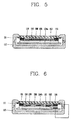
- FIG. 5 is a sectional view of the mobile terminal 100 taken along line V-V in FIG. 3 , in which the touch sheet 150 and its relevant elements are shown.
- the touch sheet 150 includes a first region 151 for forming the touch screen part 113 and a second region 152 extending from the first region 151 to form the touch keypad part 114.
- a conductive pattern 156 for sensing a touch is formed at the first and second regions 151 and 152, and can be formed by patterning a conductive material, e.g., ITO (Indium Tin Oxide), on the touch sheet 150.
- ITO Indium Tin Oxide
- the conductive pattern 156 may be formed as a single layer on one surface of the touch sheet 150 in zigzags. As shown in FIG. 5 , in the present exemplary embodiment, the conductive pattern 156 is formed at an inner side of the touch sheet 150. However, the conductive pattern 156 may also be formed at an outer side of the touch sheet 150.
- the conductive pattern 156 of the first region 151 has a zigzag form in a lengthwise direction of the first body 110, namely, in the direction from the audio output unit 115 to the first manipulation unit 117.
- the conductive pattern 156 also includes bent points 157a and 157b that are formed at the left and right sides of the conductive pattern 156 in zigzags, at which the direction of the pattern changes. Further, two lines adjacent to the bent point 157b are symmetrical based on a horizontal line 157c (virtual line) that passes through the bent point 152b.
- the user's finger comes in contact with the window 136, the user's finger is positioned on the region where the conductive pattern 156 is formed on the touch sheet 150.
- the positioning of the user's finger on the region where the conductive pattern 156 is formed will be referred to as 'contacting' the conductive pattern 156 for the sake of explanation.
- the conductive pattern 156 is configured such that the user's finger (F) comes into contact with at least two lines 157d and 157e.
- a maximum distance between the two lines 157d and 157e is set to be shorter than the size of the user's finger (F).
- both ends (X, Y) of the conductive pattern 151 are connected with a data line 153 disposed at an edge of the touch sheet 150.
- the data line 153 transfers a touch signal inputted to the conductive pattern 156 to the interior of the first body 110, for which an end of the data line 153 is connected to the PCB 134 by the FPCB 141.
- conductive patterns 158 of the second region 152 implement a key input unit for inputting information by touching a pre-set region.
- touch key parts 154 are formed to be spaced apart at the second region 152. In the present exemplary embodiment, the touch key parts 154 are disposed to be spaced apart up/down and left/right centering around the through hole 150a.
- the mounting holes 150b are also illustrated in FIG. 4 .
- FIG. 5 is a sectional view of the mobile terminal 100 taken along line V-V in FIG. 3 , in which the touch sheet 150 and its relevant elements are shown.
- FIG. 6 is a sectional view of the mobile terminal 100 taken along line VI-VI in FIG. 3 .
- the illumination sheet 160 is disposed at an inner side of the second region 152, and is configured to display an illumination pattern at the touch keypad part 114.
- the shielding pattern 155 is formed at edges of the touch sheet 150, and minimizes an external influence, namely, an influence of electromagnetic waves generated from electronic components on signals of the conductive pattern (e.g., signals transferred via the data line 153).
- the shielding pattern 155 may be formed by depositing a conductive material, e.g., a metallic material, on the touch sheet 150.
- the shielding pattern 155 is also formed at a position corresponding to the data line 153, and is formed at an opposite side of the surface on which the data line 153 is positioned.
- the data line 153 is formed at an inner side of the touch sheet 150
- the shielding pattern 155 is formed at an outer side of the touch sheet 150.
- the data line 153 may be formed at the outer side of the touch sheet 150 while the shielding pattern 155 may be formed at the inner side of the touch sheet 150.
- the conductive patterns 156 and 158 may be formed on the same surface on which the data line 153 is positioned.
- a ground 161 is formed at the illumination sheet 160, and the shielding pattern 155 is electrically short-circuited with the ground 161.
- the ground 161 of the illumination sheet 160 and the shielding pattern 155 can be connected in various manners, for example, by a cable or through contact point connection. Therefore, by electrically short-circuiting the shielding pattern 155 and the ground 161 of the illumination sheet 160, an influence of a voltage generated from the illumination sheet 160 on an operation of the touch sheet 150 can be minimized.
- FIGs. 7A to 7D are front views of illumination sheets in FIG. 3 , in which the operations of the illumination sheet 160 when the touch keypad part 114 is touched are shown in the order of time.
- the illumination sheet 160 includes illumination patterns 162 individualized to separately illuminate the touch key parts 154 when the touch keypad part 114 is touched. Further, the illumination pattern 162 is illuminated when a touch is applied to one of the touch key parts 154 to thus allow a user to recognize that the touch has been inputted to the touch key part 154.
- each illumination pattern 162 is positioned at regions corresponding to the touch key parts 154, and in the embodiment shown in FIGs. 7A to 7D , each illumination pattern 162 has concentric circles each having a different radius.
- the illumination patterns 162 disposed at the right portion of the illumination sheet 160 will be taken as an example.
- the circles indicated by solid lines indicate an illuminated state
- the circles indicated by dotted lines indicate a non-illuminated state.
- the illumination patterns 162 include first to fourth illumination patterns 162a to 162d having different radiuses, and in which the illumination patterns 162a to 162d are sequentially arranged according to their radius.
- each of the illumination patterns 162a to 162d may be made of a material having a brightness that can be controlled according to strength of a current, and may be individually controlled to have a brightness that changes in turn along an ambient direction in the order of time.
- the darker solid lines with a greater thickness compared to the other illumination patterns 162 indicate illumination patterns with the highest brightness.
- the illumination patterns 162 may be configured such that the first to fourth illumination patterns 162a to 162d are in the state of being brightest in turn over time. For example, as shown in FIG. 7A , when a touch is input to the touch key parts 154 of the touch sheet 150, the first illumination pattern 162a is controlled to be the brightest, and when time passes by, and as shown in FIG. 7B , the first illumination pattern 162a becomes dark while the second illumination pattern 162 is controlled to be the brightest.
- the third illumination pattern 162c becomes the brightest
- the fourth illumination pattern 162d becomes the brightest
- the illuminations of the first to fourth illumination patterns 162a to 162d are stopped. Therefore, when the user inputs a touch to the touch keypad part 114, the illumination patterns 162 of the corresponding touch keypad part 114 are illuminated, and at this time, visual effects are implemented such that light is diffused in a ring shape along the ambient direction.
- the illumination patterns 162 may be individually controlled to be brightest starting from the fourth illumination pattern 162d to the first illumination pattern 162a in turn, whereby light in the ring form can be diffused along the inward direction over time.
- four illumination patterns 162a to 162d are sequentially arranged, but the number of illumination patterns may vary as necessary.
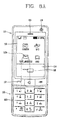
- FIGs. 8A to 8C are plan views of the mobile terminal used to explain operations of the mobile terminal according to an embodiment of the present invention.
- the touch screen part 130 includes a menu or an icon 113c for operating various functions of the mobile terminal 100.
- the part of the menu or the icon 113c e.g., a text message
- the corresponding function is performed.
- the touch screen part 113 also includes a list 113d that can be selected, and a cursor or a pointer 113e positioned on the list 113d.
- the touch keypad part 114 may be implemented in the form of a direction key that can move the cursor or the pointer positioned on the list 113d. In this instance, when the touch keypad part 114 is touched, the illumination pattern of the illumination sheet is displayed on the touch keypad part 114 to allow the user to recognize the touch keypad part 114 has been touched.
- the list 113d is a phone book list, and in this instance, by touching the region corresponding to the touch key part 154 positioned at the lower portion ( FIG. 4 illustrates the touch key part 154), the cursor or the pointer 113c may be moved downwardly, and then, by pressing the center key 118 positioned at the central region, information (e.g., a phone number) desired to be obtained by the user can be displayed on the touch screen part 113. Further, as shown in FIG. 8B , when the user touches the lower portion of the touch key part 154 to scroll down the phone book list, the illumination patterns 162 are illuminated based on the amount of time the user touches the touch key part 154.
- the user may input characters, numbers, symbols, etc., to the terminal by manipulating the second and third manipulating units 123 and 124 and manipulating the touch key part 154.
- the user can also select a phone number, for example, by touching the phone icon on the first manipulating unit117.
- the user can easily input and select different options on the terminal and see that the appropriate regions have been touched.
- the menu or the icons displayed in the touch screen part 113 may be displayed with a size corresponding to the user's finger or a larger size for the user's convenient touch input.
- the conductive pattern 156 of the touch sheet 150 according to embodiments of the present invention is suitable for sensing the touch inputted to the recognition region formed with such a size as described above.
- FIG. 9 is a plan view of a touch sheet 250 according to a second embodiment of the present invention
- FIG. 10 is a sectional view of the mobile terminal with the touch sheet in FIG. 9 mounted on a first body.
- the touch sheet 250 and its relevant elements are exaggerated for illustration purposes.
- the touch sheet 250 includes a first region 251 and a second region 252 that extends from the first region.
- FIGs. 9 and 10 also illustrate a data line 253, touch key part 254, front case 211, rear case 212, display module 235, PCB 234a, window 236, etc. that correspond with similar components shown in the other above-described figures (except the reference numerals have been increased by 100).
- FIG. 10 also illustrates an insulation layer 265 provided on an inner surface of the conductive pattern 256 formed at the touch sheet 250, and a conductive layer 264 formed on an inner surface of the insulation layer 265 by vacuum-depositing (e.g., sputtering) a transparent conductive material.
- the conductive layer 264 formed at the first region 251 and the data line 253 is disposed on edges of the conductive layer 264 and electrically connected with the conductive layer 264.
- the data line 253 surrounds the edges of the first and second regions 251 and 252 and may be also electrically connected with the conductive patterns 256 and 258 of the first and second regions 251 and 252.
- a shielding pattern 255 is formed at edges of the touch sheet 250 in order to minimize an external influence, namely, an influence of electromagnetic waves generated from the electronic components on signals transferred through the data line 2532.
- electric field generating portions P1 to P4 for generating an electric field at the conductive layer 264 are disposed at edges of the conductive layer 264.
- the electric field generating parts P1 to P4 may also be disposed at portions corresponding to vertexes of the rectangular first region 251 and electrically connected with the data line 253.
- a correction pattern 259 for linearly correcting the electric field generated at the conductive layer 264 is formed at the edges of the conductive layer 264, namely, between the conductive layer 264 and the data line 253. Also, the correction pattern 259 is configured such that a conductive material forms a particular pattern. Therefore, the form of electric field according to interaction between the current flowing through the correction pattern 259 and the electric field generated at the conductive layer 264 is corrected to correspond to the rectangular shape of the first region 251.
- FIG. 11 shows a schematic circuit diagram when a point (P) of the first region 251 shown in FIG. 9 is touched.
- the electric field formed at the conductive layer 264 may be simply replaced by the circuit diagram having one capacitor (C) and four resisters R1 to R4 based on the touched point (P).
- the mobile terminal according to the present embodiment further includes the touch sensing method using the conductive layer 264 and the electric field generating parts (P1 to P4) in addition to the touch sensing by virtue of the conductive pattern 256, the precision and accuracy of the touch sensing is improved without affecting the thickness of the touch sheet 250.
- FIG. 12 is a perspective view of a mobile terminal according to another embodiment of the present invention
- FIG. 13 is an exploded perspective view of the mobile terminal in FIG. 12 .
- Reference numerals shown in FIG. 12 are similar to the reference numerals shown in FIG. 1 , but are increased by 200 from the reference numerals shown in FIG. 1 .
- the mobile terminal includes a first region 313a and a second region 314a formed on a front surface of a first body 310.
- a touch screen part 313 and a touch keypad part 314 are disposed on the first and second regions 313a and 314a, respectively.
- a window 336 made of a transmissive material is mounted on a front side of the first region 313a, and a touch sheet 350 for sensing a touch is mounted at an inner side of the window 336.
- the touch sheet 350 senses the touch and transfers a touch signal to the interior of the terminal body.
- the conductive patterns formed on the touch sheet 350 can be formed in the same or similar manner as for the conductive patterns 156 and 256 in the former embodiments.
- the insulating layer and the electric field generating parts P1 to P4 may be disposed on the touch sheet 350 in a similar manner as in FIGs. 9 and 10 .
- a touch panel 319 is mounted on the front face of the second region 314a, and is formed in a plate shape.
- touch sensors 319a that sense a touch are mounted at an inner side of the touch panel 319.
- the touch sensors 319a are separately mounted at appropriate positions on a PCB 336. Thus, when a region corresponding to the touch sensors 319a of the touch panel is touched, the touch sensors 319a sense the touch and transfer a touch signal to the PCB 336.
- a through hole 318a is formed at a central portion of the touch panel 319, and a center key 318 that can be pressed is mounted in the through hole 318a.
- a switch 318b that inputs information according to a pressing operation of the center key 318 is also mounted at an inner side of the center key 318.
- an illumination sheet 360 that displays an illumination pattern on the touch panel 319 is mounted at an inner side of the touch panel 319, and the configuration and operation of the illumination sheet 360 is the same as that in the former embodiments, so its description will be omitted.
- Other reference numerals shown in FIG. 13 that have not been described correspond to similar reference numerals shown in FIG.3
- the present invention is applicable to all types of mobile terminals such as a bar type mobile terminal, a folder type mobile terminal, a swing type mobile terminal, a swivel type mobile terminal, and the like.
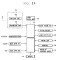
- FIG. 14 is a schematic block diagram of a mobile terminal according to an embodiment of the present invention.
- the mobile terminal 100 in FIG. 1 will be explained, but it can be also applicable to the mobile terminal 300 shown in FIG. 12 .
- the mobile terminal includes a wireless communication module 171, the manipulation units 117, 123 and 124, the image input units 116 and 128, the audio input unit 125, the touch screen part 113, the touch keypad part 114, the audio output unit 115, a sensing unit 176, the interface 126, a broadcast receiving module 175, a memory 174, a power supply unit 130, and a controller 170.
- the controller 170 controls the overall operations of the mobile terminal.
- the controller 180 performs the controlling and processing associated with voice calls, data communications, video calls, and the like.
- the controller 170 also receives a touch signal inputted to the touch screen part 113 and the touch keypad part 114 and controls other electronic components to operate relevant operations of the mobile terminal.
- the wireless communication module 171 transmits/receives radio signals to/from a network (e.g., mobile communication base station) via an antenna.
- a network e.g., mobile communication base station
- the wireless communication module 171 includes a transmitting unit 172 that handles the transmission and reception of audio data, text data, image data and control data, modulates transmission signals and transmits the modulated signal, and a receiving unit 173 that demodulates received signals under the control of the controller 170.
- the manipulation units 117, 123 and 124 are configured as shown in the above-described embodiments and provide key input data input by the user to control operations of the terminal to the controller 170.
- the image input units 116 and 128 process image frames such as still images or video acquired by an image sensor or the like in a video call mode or an image capturing mode. The processed image frames are converted into image data that can be displayed or output on the touch screen part 113.
- the image frames processed by the image input units 116 and 128 may be stored in the memory 174 or transmitted externally through the wireless communication module 171 under the control of the controller 170.
- the audio input unit 125 receives external audio signals via a microphone in a phone call mode, a recording mode or a voice recognition mode, etc., and processes the received audio signals into electrical voice data.
- the processed voice data is converted into a form that can be transmitted to the network (e.g., mobile communication base station) via the wireless communication module 171.
- the processed voice data is output and stored in the memory 174.
- the audio input unit 125 may include various types of noise canceling or suppression algorithms to cancel or suppress noise generated in the course of receiving and transmitting audio signals.
- the touch screen part 113 outputs information processed in the mobile terminal.
- the touch screen part 113 may display a User Interface (UI) or a Graphic User Interface (GUI) associated with a call or other communication mode under the control of the controller 170.
- UI User Interface
- GUI Graphic User Interface
- the touch screen part 113 may display a captured image and/or received image, a UI, a GUI, and the like, under the control of the controller 170.
- the touch screen part 113 may be used as an input device that inputs information in a tactile manner.
- the audio output unit 115 converts audio data received from the wireless communication module 171 or stored in the memory 174 and outputs the converted data in a call signal reception mode, a phone call mode, a recording mode, a voice recognition mode, and the like, under the control of the controller 170.
- the audio output module 115 provides audible outputs related to a particular function (e.g., a call signal reception sound, a message reception sound, etc.) performed by the mobile terminal.
- the sensing unit 176 detects a current status (or state) of the mobile terminal 100 such as an open/close state of the mobile terminal 100, a location of the mobile terminal 100, presence or absence of user contact with the mobile terminal, etc., and generates a sense or control signal for controlling the operation of the mobile terminal.
- the sensing unit 176 senses whether the slide phone is opened or closed and outputs the sensing result to the controller 170 to thereby control the operations of the terminal 100.
- the sensing unit 176 can detect whether or not the power supply unit 130 supplies power to the terminal and whether or not the external interface 126 is coupled with an external device.
- the sensing unit 176 senses the touch and applies a touch signal to the controller 170.
- the sensing unit 176 senses a change in an amount of charge generated from the conductive patterns 156 and 158 and transfers the same to the controller 170.
- the sensing unit 176 senses the touch and applies a corresponding signal to the controller 170. Then, the controller 170 operates a corresponding function of the menu or the icon 113c. In addition, when the user touches the touch keypad part 114, the sensing unit 176 senses the user's touch and applies a signal to the controller 170.
- the controller 170 applies a signal for moving the cursor 113e in the list (e.g., the list 113d in FIG. 8B ) displayed on the touch screen part 113, and at the same time, applies a signal for illuminating the illumination patterns 162 in FIGs. 7A to 7dD to the illumination sheet 160.
- the controller 170 individually controls the illumination patterns 162a to 162d such that brightness of the illumination patterns 162a to 162d in the concentric circles changes in the order of time.
- the interface 126 serves as an interface for at least one external device connected with the mobile terminal.
- the external device may include a wired/wireless headset, an external power charger, a wired/wireless data port, a card socket (e.g., for receiving a memory card, a Subscriber Identity Module/User Identity Module (SIM/UIM) card, etc.), and the like.
- the interface 126 may also be used to receive inputs (e.g., data, information, power, etc.) from an external device and transfer the received inputs to one or more elements within the mobile terminal, or may be used to transfer data from the mobile terminal to another external device.
- the memory 174 stores programs or the like used for the processing and controlling operations performed by the controller 170, or may temporarily store inputted/outputted data (e.g., a phonebook, messages, still images, video, etc.). Also, the memory 174 stores a program that controls the overall operations of the mobile terminal 100 according to embodiments of the present invention.
- the memory 174 may also include at least one type of storage medium including a hard disk type, a card-type memory (e.g., SD or XD memory, etc), a flash memory, a Random Access Memory (RAM), a Read-Only Memory (ROM), and the like.
- the broadcast receiving module 175 receives a broadcast signal transmitted through a satellite or terrestrial service, convert the same into a broadcast data format that can be output to the touch screen part 113 and the audio output unit 115 and outputs the converted data to the controller 170. Further, the broadcast receiving module 175 also receives supplementary data associated to a broadcast (e.g., Electronic Program Guide (EPG), a channel list, etc.).
- EPG Electronic Program Guide
- the broadcast data and supplementary data is then converted by the broadcast receiving module 175 and may be stored in the memory 174.
- the power supply unit 130 is provided with an internal or external power source and supplies power used for operating the different elements of the terminal under the control of the controller 170.
- the mobile terminal according to embodiments of the present invention has several advantages. That is, first, because the touch screen part and the touch pad part are provided to the first and second regions, respectively, formed on the front surface of the terminal body, a convenient user interface environment is provided and the design of the mobile terminal is simplified.
- the illumination sheet including the illumination patterns for individually illuminating the touch key parts allows the user to effectively recognize a touch input, and because the illumination patterns in the concentric circles are individually controlled such that their brightness changes in the order of time, the user can easily see the operations of the touch parts.
- the touch sheet may be formed to be thinner and have an improved light transmittance. Also, because a conductive material is used for the conductive pattern, the overall material costs of the terminal can be reduced.
- the touch sensing method using a single layer the touch sensing method using the conductive layer formed through vacuum deposition and the electric field generating unit are applied in conjunction, and the accuracy of touch sensing is improved without significantly affecting the thickness of the touch sheet.
- the input method uses the touch screen and the touch pad, a more convenient user interface is provided.
Landscapes
- Engineering & Computer Science (AREA)
- Theoretical Computer Science (AREA)
- General Engineering & Computer Science (AREA)
- Physics & Mathematics (AREA)
- General Physics & Mathematics (AREA)
- Human Computer Interaction (AREA)
- Computer Hardware Design (AREA)
- Signal Processing (AREA)
- Mathematical Physics (AREA)
- Telephone Set Structure (AREA)
- Position Input By Displaying (AREA)
- Telephone Function (AREA)
- Input From Keyboards Or The Like (AREA)
- User Interface Of Digital Computer (AREA)
Claims (28)
- Mobiles Endgerät, das aufweist:einen Endgerätekörper (110);ein Fenster (136), das auf den Endgerätekörper montiert ist und erste und zweite Bereiche (113a, 114a) hat;einen berührungsempfindlichen Bildschirmteil (113), der dem ersten Bereich des Fensters (136) entspricht und der aufgebaut ist, um eine Berührung auf dem ersten Bereich des Fensters (136) abzutasten;ein Anzeigemodul (135), das unter einer Fläche des Fensters angeordnet ist, wobei die Fläche dem ersten Bereich (113a) entspricht, und das aufgebaut ist, um visuelle Informationen anzuzeigen;eine berührungsempfindliche Taste, die auf dem zweiten Bereich (114a) des Fensters angeordnet ist und die aufgebaut ist, um eine darauf angewendete Berührung abzutasten,dadurch gekennzeichnet, dass das mobile Endgerät ferner aufweist:ein Durchgangsloch (136a), das in dem zweiten Bereich des Fensters (136) ausgebildet ist; undeine mittlere Taste (118), die in dem Durchgangsloch (136a) angeordnet ist und aufgebaut ist, um gedrückt zu werden.
- Mobiles Endgerät (100) nach Anspruch 1, wobei ein Außenumfang der mittleren Taste (118) von dem Fenster (136) vollständig umschlossen ist.
- Mobiles Endgerät (100) nach Anspruch 1 oder Anspruch 2, wobei eine Größe und eine Form der mittleren Taste (118) einer Größe und einer Form des Durchgangslochs (136a) entsprechen.
- Mobiles Endgerät (100) nach einem der Ansprüche 1 bis 3, wobei die mittlere Taste (118) aus dem Fenster (136) vorsteht.
- Mobiles Endgerät (100) nach einem der Ansprüche 1 bis 4, wobei die berührungsempfindliche Taste berührungsempfindliche Tastenteile (154) aufweist, die an mehreren Positionen innerhalb des Bereichs (114a) getrennt angeordnet sind.
- Mobiles Endgerät (100) nach Anspruch 5, wobei die mittlere Taste (118) zwischen berührungsempfindlichen Tastenteilen (154) angeordnet ist, und
wobei die mittlere Taste (118) und die berührungsempfindlichen Tastenteile (154) in der Breitenrichtung des Endgerätekörpers (110) ausgerichtet sind. - Mobiles Endgerät (100) nach einem der Ansprüche 1 bis 6, wobei eine Auswahlliste (113d) auf dem berührungsempfindlichen Bildschirmteil (113) angezeigt wird, und ein Cursor oder ein Zeiger (113e) auf der Liste (113d) positioniert wird.
- Mobiles Endgerät (100) nach Anspruch 7, wobei die berührungsempfindliche Taste in der Form einer Richtungstaste implementiert ist, die den auf der Liste (113d) angeordneten Cursor oder Zeiger bewegen kann.
- Mobiles Endgerät (100) nach einem der Ansprüche 1 bis 8, wobei der berührungsempfindliche Bildschirmteil (113) eine berührungsempfindliche Schicht (150) aufweist, die zwischen dem Fenster (136) und dem Anzeigemodul (135) angeordnet ist und aufgebaut ist, um eine Berührung auf dem ersten Bereich (113a) des Fensters (136) abzutasten.
- Mobiles Endgerät (100) nach Anspruch 9, wobei die berührungsempfindliche Schicht (150) als eine berührungsempfindliche Lage implementiert ist, die aus einem transparenten Material gefertigt ist.
- Mobiles Endgerät (100) nach Anspruch 10, wobei die berührungsempfindliche Lage an einer Innenseite des Fensters (136) zum Abtasten einer auf das Fenster (136) angewendeten Berührung befestigt ist.
- Mobiles Endgerät (100) nach einem der Ansprüche 10 oder 11, wobei die berührungsempfindliche Lage sich zu dem zweiten Bereich des Fensters (136) zum Abtasten einer auf die berührungsempfindliche Taste angewendeten Berührung erstreckt.
- Mobiles Endgerät (100) nach Anspruch 12, das ferner aufweist:ein Loch (150a), das entsprechend dem Durchgangsloch des Fensters (136) an dem Berührungsbildschirm ausgebildet ist.
- Mobiles Endgerät (100) nach einem der Ansprüche 9 bis 13, wobei die berührungsempfindliche Schicht (150) aufweist:einen Abschirmungsabschnitt (155), der auf einer Oberfläche der berührungsempfindlichen Schicht (150) positioniert ist und aufgebaut ist, um einen Einfluss von elektromagnetischen Wellen, die von elektronischen Komponenten erzeugt werden, zu blockieren.
- Mobiles Endgerät (100) nach einem der Ansprüche 1 bis 14, das ferner aufweist:eine Beleuchtungseinheit (160), die unter dem zweiten Bereich (114a) angeordnet ist und aufgebaut ist, um die berührungsempfindliche Taste zu beleuchten.
- Mobiles Endgerät (100) nach Anspruch 15, wobei die Beleuchtungseinheit (160) beleuchtet wird, wenn auf die berührungsempfindliche Taste eine Berührung angewendet wird.
- Mobiles Endgerät (100) nach Anspruch 15 oder 16, wobei die Beleuchtungseinheit (160) die berührungsempfindliche Taste einzeln beleuchtet.
- Mobiles Endgerät (100) nach einem der Ansprüche 15 bis 17, wobei die berührungsempfindliche Taste berührungsempfindliche Tastenteile (154) aufweist, die an mehreren Positionen innerhalb des zweiten Bereichs (114a) getrennt angeordnet sind, und
wobei die Beleuchtungseinheit (160) vereinzelte Beleuchtungsmuster (162) aufweist, die aufgebaut sind, um die entsprechenden berührungsempfindlichen Tastenteile (154) zu beleuchten. - Mobiles Endgerät (100) nach einem der Ansprüche 1 bis 18, wobei der Endgerätekörper aufweist:einen ersten Körper (110); undeinen zweiten Körper (120), der mit dem ersten Körper (110) verbunden ist, um sich verschiebbar in Bezug auf den ersten Körper (110) zu bewegen,wobei der erste Körper (110) die ersten und zweiten Bereiche (113a, 114a) umfasst, die auf seiner vorderen Oberfläche ausgebildet sind, undwobei der zweite Körper (120) eine Tastatur (123) aufweist, die auf seiner vorderen Oberfläche ausgebildet ist und aufgebaut ist, um Zahlen, Buchstaben oder Symbole einzugeben.
- Mobiles Endgerät (100) nach einem der Ansprüche 1 bis 19, wobei der Endgerätekörper (110) ein Gehäuse (111) mit einem Fenstermontageteil (138) aufweist, der gegenüber einer Oberfläche des Gehäuses vertieft ist, um das Fenster (136) aufzunehmen.
- Mobiles Endgerät (100) nach Anspruch 20, wobei der Endgerätekörper (110) ferner einen Halterahmen (139) aufweist, der an dem Fenstermontageteil (138) montiert ist und eine Handhabungseinheit (117) hat, die an einem Bereich des Halterahmens (139) ausgebildet ist, und
wobei ein Schalter (117a) auf einer Innenseite des Halterahmens montiert ist und aufgebaut ist, um Informationen gemäß einer Druckbedienung einer Handhabungseinheit (117) einzugeben. - Mobiles Endgerät (100) nach Anspruch 20 oder 21, das ferner aufweist:eine erste Bildeingabeeinheit (116), die unter dem Fenster angeordnet ist und aufgebaut ist, um ein Bild oder ein Video aufzunehmen; undeine Öffnung, die an dem Fenstermontageteil (138) entsprechend der ersten Bildeingabeeinheit (116) ausgebildet ist.
- Mobiles Endgerät (100) nach Anspruch 22, das ferner aufweist:eine zweite Bildeingabeeinheit (128) mit einer Bildaufnahmerichtung, die im Wesentlichen entgegengesetzt zu der der ersten Bildeingabeeinheit (116) ist.
- Mobiles Endgerät (100) nach Anspruch 23, wobei die ersten und zweiten Bildeingabeeinheiten (116, 128) Kameras sind, die aufgebaut sind, um eine voneinander unterschiedliche Anzahl von Bildpunkten zu unterstützen.
- Mobiles Endgerät (100) nach einem der Ansprüche 1 bis 24, wobei das Anzeigemodul (135) ein Flüssigkristallanzeigen- (LCD-) Modul oder ein organisches Leuchtdioden- (OLED-) Modul aufweist.
- Mobiles Endgerät (100) nach einem der Ansprüche 1 bis 25, wobei das Fenster (136) aus Kunstharz oder Hartglas gefertigt ist.
- Mobiles Endgerät (100) nach einem der Ansprüche 1 bis 26, das ferner aufweist:eine Abtasteinheit (176), die aufgebaut ist, um einen aktuellen Status des mobilen Endgeräts (100) zu erfassen und ein Abtastsignal zum Steuern eines Betriebs des mobilen Endgeräts (100) zu erzeugen.
- Mobiles Endgerät (100) nach einem der Ansprüche 1 bis 27, das ferner aufweist:eine Schnittstelle (126), die aufgebaut ist, um zuzulassen, dass das mobile Endgerät (100) Daten mit einer externen Vorrichtung austauscht,wobei die Schnittstelle (126) als ein Kartensteckfach zum Aufnehmen einer externen Karte darin implementiert ist,wobei die Schnittstelle (126) auf einer Seite des Endgerätekörpers (110) angeordnet ist, undwobei die externe Karte als ein Teilnehmerkennungsmodul (Subscriber Identity Module, SIM), ein Nutzerkennungsmodul (User Identity Modul, UIM) oder eine Speicherkarte zum Speichern von Informationen implementiert ist.
Priority Applications (2)
| Application Number | Priority Date | Filing Date | Title |
|---|---|---|---|
| EP14151191.5A EP2722738B1 (de) | 2007-11-06 | 2008-09-04 | Mobiles Endgerät |
| PL08163667T PL2058727T3 (pl) | 2007-11-06 | 2008-09-04 | Terminal przenośny z gładzikiem i ekranem dotykowym |
Applications Claiming Priority (2)
| Application Number | Priority Date | Filing Date | Title |
|---|---|---|---|
| KR1020070112864A KR101301521B1 (ko) | 2007-11-06 | 2007-11-06 | 휴대 단말기 |
| KR1020070113394A KR101301522B1 (ko) | 2007-11-07 | 2007-11-07 | 휴대 단말기 |
Related Child Applications (2)
| Application Number | Title | Priority Date | Filing Date |
|---|---|---|---|
| EP14151191.5A Division EP2722738B1 (de) | 2007-11-06 | 2008-09-04 | Mobiles Endgerät |
| EP14151191.5A Division-Into EP2722738B1 (de) | 2007-11-06 | 2008-09-04 | Mobiles Endgerät |
Publications (3)
| Publication Number | Publication Date |
|---|---|
| EP2058727A2 EP2058727A2 (de) | 2009-05-13 |
| EP2058727A3 EP2058727A3 (de) | 2012-02-29 |
| EP2058727B1 true EP2058727B1 (de) | 2014-03-05 |
Family
ID=40010738
Family Applications (2)
| Application Number | Title | Priority Date | Filing Date |
|---|---|---|---|
| EP08163667.2A Active EP2058727B1 (de) | 2007-11-06 | 2008-09-04 | Mobiles endgerat mit beruhrungsempfindlicher flache und beruhrungsempfindlichem bildschirm |
| EP14151191.5A Active EP2722738B1 (de) | 2007-11-06 | 2008-09-04 | Mobiles Endgerät |
Family Applications After (1)
| Application Number | Title | Priority Date | Filing Date |
|---|---|---|---|
| EP14151191.5A Active EP2722738B1 (de) | 2007-11-06 | 2008-09-04 | Mobiles Endgerät |
Country Status (9)
| Country | Link |
|---|---|
| US (3) | US8249661B2 (de) |
| EP (2) | EP2058727B1 (de) |
| JP (1) | JP4849483B2 (de) |
| CN (1) | CN103761040B (de) |
| DE (1) | DE202008018311U1 (de) |
| ES (1) | ES2468245T3 (de) |
| MX (1) | MX2008008909A (de) |
| PL (1) | PL2058727T3 (de) |
| TW (1) | TWI406551B (de) |
Families Citing this family (54)
| Publication number | Priority date | Publication date | Assignee | Title |
|---|---|---|---|---|
| US7362585B2 (en) * | 2005-02-11 | 2008-04-22 | Research In Motion Limited | Frame for a device mounted above a printed circuit board in an electronic device |
| WO2008116486A1 (en) * | 2007-03-23 | 2008-10-02 | Nokia Corporation | Sliding module with electrical connection paths |
| TWI406551B (zh) * | 2007-11-06 | 2013-08-21 | Lg Electronics Inc | 行動式終端機 |
| US7907983B1 (en) * | 2008-03-25 | 2011-03-15 | Sprint Communications Company L.P. | Wireless handset with locking slider |
| KR101464537B1 (ko) * | 2008-10-01 | 2014-11-24 | 삼성전자주식회사 | 디지털 카메라의 사용자 인터페이스 모듈 및 이를 구비한 디지털 카메라 |
| USD603355S1 (en) * | 2008-11-19 | 2009-11-03 | Samsung Electronics Co., Ltd. | Portable telephone |
| CA131819S (en) * | 2009-02-20 | 2010-03-22 | Lg Electronics Inc | Mobile phone |
| WO2010126072A1 (ja) * | 2009-04-28 | 2010-11-04 | 日本電気株式会社 | タッチパネル、タッチパネルの製造方法及び電子機器 |
| USD621378S1 (en) * | 2009-06-02 | 2010-08-10 | Saumsung Electronics Co., Ltd. | Mobile phone |
| TWI386656B (zh) * | 2009-07-02 | 2013-02-21 | Novatek Microelectronics Corp | 電容值測量電路與方法 |
| US8441465B2 (en) | 2009-08-17 | 2013-05-14 | Nokia Corporation | Apparatus comprising an optically transparent sheet and related methods |
| WO2011032521A1 (zh) | 2009-09-21 | 2011-03-24 | 北京联想软件有限公司 | 电子设备及其实现预设操作指令的方法、手机和程序 |
| JP5674415B2 (ja) * | 2009-10-28 | 2015-02-25 | 京セラ株式会社 | 携帯通信端末 |
| JP5456450B2 (ja) * | 2009-12-01 | 2014-03-26 | インテレクチュアル ベンチャーズ ファンド 83 エルエルシー | 撮像装置及び操作装置 |
| KR101645461B1 (ko) | 2010-01-12 | 2016-08-12 | 삼성전자주식회사 | 휴대용 단말기에서 근거리 무선 네트워크 자동 연결 방법 및 장치 |
| JP2011187384A (ja) * | 2010-03-10 | 2011-09-22 | Nec Casio Mobile Communications Ltd | 押圧キー構造、及び、電子機器 |
| KR101609888B1 (ko) * | 2010-04-22 | 2016-04-06 | 엘지전자 주식회사 | 휴대용 디스플레이 장치 |
| JP2012022289A (ja) * | 2010-06-11 | 2012-02-02 | Nintendo Co Ltd | 携帯型電子機器 |
| JP5477962B2 (ja) * | 2010-09-02 | 2014-04-23 | シャープ株式会社 | タッチリモコン、電子機器システム |
| JP5615647B2 (ja) * | 2010-09-24 | 2014-10-29 | 株式会社ジャパンディスプレイ | タッチ検出機能付き表示装置および電子機器 |
| USD645836S1 (en) * | 2010-10-12 | 2011-09-27 | Samsung Electronics Co., Ltd. | Mobile phone |
| JP5432193B2 (ja) | 2011-01-18 | 2014-03-05 | 株式会社ジャパンディスプレイ | 表示装置 |
| JP2012221275A (ja) | 2011-04-11 | 2012-11-12 | Hosiden Corp | タッチパネル及びこれを備えた携帯端末装置 |
| USD652404S1 (en) * | 2011-04-19 | 2012-01-17 | Samsung Electronics Co., Ltd. | Mobile phone |
| JP5858641B2 (ja) * | 2011-05-10 | 2016-02-10 | キヤノン株式会社 | 情報処理装置、情報処理装置と外部装置とを含むシステム、システムの制御方法、及びプログラム |
| KR101832954B1 (ko) * | 2011-05-11 | 2018-04-13 | 엘지전자 주식회사 | 이동 단말기 |
| JP2013008231A (ja) * | 2011-06-24 | 2013-01-10 | Nissha Printing Co Ltd | 静電容量方式にも抵抗膜方式にも対応可能な押圧検出機能を有するタッチパネル |
| KR101830670B1 (ko) * | 2011-06-27 | 2018-02-21 | 엘지전자 주식회사 | 이동 단말기 |
| US9124303B2 (en) * | 2011-10-19 | 2015-09-01 | Nokia Technologies Oy | Apparatus and method for near field communication |
| USD680510S1 (en) * | 2011-12-15 | 2013-04-23 | Research In Motion Limited | Handheld electronic device |
| USD679675S1 (en) * | 2011-12-15 | 2013-04-09 | Research In Motion Limited | Handheld electronic device |
| WO2013088655A1 (ja) * | 2011-12-16 | 2013-06-20 | パナソニック株式会社 | タッチパネル及び電子機器 |
| USD677645S1 (en) * | 2012-01-10 | 2013-03-12 | Samsung Electronics Co., Ltd. | Mobile terminal |
| US9332329B2 (en) * | 2012-09-28 | 2016-05-03 | Htc Corporation | Electronic apparatus |
| US9803882B2 (en) | 2013-03-15 | 2017-10-31 | Honeywell International Inc. | Housing for an electronic device internal walls |
| US9528720B2 (en) | 2013-04-30 | 2016-12-27 | Honeywell International Inc. | Display sub-assembly for an HVAC controller |
| KR102094754B1 (ko) * | 2013-12-03 | 2020-03-30 | 엘지전자 주식회사 | 이동 단말기 |
| JP5789290B2 (ja) * | 2013-12-04 | 2015-10-07 | 株式会社ジャパンディスプレイ | タッチパネル |
| JP6053184B2 (ja) * | 2014-03-18 | 2016-12-27 | 富士フイルム株式会社 | タッチパネル |
| CN104020880A (zh) * | 2014-05-27 | 2014-09-03 | 京东方科技集团股份有限公司 | 一种触摸显示装置 |
| US20150346863A1 (en) * | 2014-05-29 | 2015-12-03 | Kabushiki Kaisha Toshiba | Touch panel and electronic device with touch panel |
| US10474409B2 (en) * | 2014-09-19 | 2019-11-12 | Lenovo (Beijing) Co., Ltd. | Response control method and electronic device |
| KR102247283B1 (ko) * | 2014-10-20 | 2021-05-03 | 삼성전자주식회사 | 전자 장치 및 그의 외관 부재 제작 방법 |
| CN106155385B (zh) * | 2015-04-07 | 2023-09-15 | 安徽精卓光显技术有限责任公司 | 电子设备及其触摸屏 |
| WO2017155128A1 (ko) * | 2016-03-07 | 2017-09-14 | 주식회사 블루버드 | 보안 기능이 구비된 모바일 단말기 |
| KR102563619B1 (ko) * | 2016-12-01 | 2023-08-04 | 삼성전자 주식회사 | 병용(combined) 버튼을 가지는 전자 장치 및 전자 장치의 병용 버튼 제어방법 |
| GB201707478D0 (en) * | 2017-05-10 | 2017-06-21 | Zytronic Displays Ltd | Display arrangement |
| KR102436655B1 (ko) * | 2017-09-22 | 2022-08-26 | 삼성디스플레이 주식회사 | 표시 장치 |
| WO2019112171A1 (ko) * | 2017-12-07 | 2019-06-13 | 엘지전자 주식회사 | 반도체 발광 소자를 이용한 차량 내 디스플레이 장치 |
| US10937769B2 (en) * | 2017-12-07 | 2021-03-02 | Zkw Group Gmbh | In-vehicle display device using semiconductor light-emitting device |
| US10998296B2 (en) * | 2017-12-07 | 2021-05-04 | Zkw Group Gmbh | In-vehicle display device using semiconductor light-emitting device |
| KR102457704B1 (ko) * | 2018-04-16 | 2022-10-21 | 삼성디스플레이 주식회사 | 표시 장치 |
| US10691176B2 (en) * | 2018-07-12 | 2020-06-23 | Google Llc | Textured pattern surface for a computing device |
| US12356298B2 (en) * | 2022-11-10 | 2025-07-08 | Bank Of America Corporation | Voice surveillance system using enhanced metadata and geotagging capabilities |
Family Cites Families (33)
| Publication number | Priority date | Publication date | Assignee | Title |
|---|---|---|---|---|
| JPH08123610A (ja) | 1994-10-20 | 1996-05-17 | Fujitsu General Ltd | 入力装置 |
| JPH1039993A (ja) * | 1996-07-26 | 1998-02-13 | Fujitsu Kiden Ltd | 透明タッチパネル及びそれを利用した入力装置 |
| JP3516328B2 (ja) * | 1997-08-22 | 2004-04-05 | 株式会社日立製作所 | 情報通信端末装置 |
| US7663607B2 (en) * | 2004-05-06 | 2010-02-16 | Apple Inc. | Multipoint touchscreen |
| US7800592B2 (en) * | 2005-03-04 | 2010-09-21 | Apple Inc. | Hand held electronic device with multiple touch sensing devices |
| EP1672886A3 (de) * | 1998-03-05 | 2014-08-13 | Cliff Island LLC | Tragbares Endgerät |
| US6429846B2 (en) * | 1998-06-23 | 2002-08-06 | Immersion Corporation | Haptic feedback for touchpads and other touch controls |
| JP2000278373A (ja) * | 1999-03-29 | 2000-10-06 | Ricoh Co Ltd | 携帯型電子機器 |
| JP2001023473A (ja) * | 1999-07-07 | 2001-01-26 | Matsushita Electric Ind Co Ltd | 移動体通信端末装置およびこれに用いる透明タッチパネルスイッチ |
| JP2001086233A (ja) * | 1999-07-13 | 2001-03-30 | Denso Corp | 照明機能付携帯機器 |
| US6704004B1 (en) | 2000-08-17 | 2004-03-09 | Nokia Mobile Phones Ltd. | Arrangement for integration of key illumination into keymat of portable electronic devices |
| US6718182B1 (en) * | 2000-09-18 | 2004-04-06 | Compal Electronics, Inc. | Modularized functionality enhancement for a cellular telephone |
| JP2002287850A (ja) * | 2001-03-23 | 2002-10-04 | Toshiba Corp | 携帯情報端末 |
| US6892081B1 (en) * | 2001-05-31 | 2005-05-10 | Nokia Corporation | Mobile terminal and method of operation using content sensitive menu keys in keypad locked mode |
| JP3926590B2 (ja) | 2001-07-24 | 2007-06-06 | アルプス電気株式会社 | 座標入力装置及び電子機器 |
| US7046230B2 (en) * | 2001-10-22 | 2006-05-16 | Apple Computer, Inc. | Touch pad handheld device |
| US7333092B2 (en) * | 2002-02-25 | 2008-02-19 | Apple Computer, Inc. | Touch pad for handheld device |
| GB2386707B (en) | 2002-03-16 | 2005-11-23 | Hewlett Packard Co | Display and touch screen |
| CN1160661C (zh) | 2003-03-18 | 2004-08-04 | 中国电子科技集团公司第五十五研究所 | 用介质层校正电场分布非线性的触摸屏 |
| US7499040B2 (en) * | 2003-08-18 | 2009-03-03 | Apple Inc. | Movable touch pad with added functionality |
| US7495659B2 (en) * | 2003-11-25 | 2009-02-24 | Apple Inc. | Touch pad for handheld device |
| JP2005210649A (ja) * | 2004-01-26 | 2005-08-04 | Kato Electrical Mach Co Ltd | 携帯端末のスライド機構 |
| JP4559092B2 (ja) * | 2004-01-30 | 2010-10-06 | 株式会社エヌ・ティ・ティ・ドコモ | 携帯通信端末及びプログラム |
| CN2748977Y (zh) | 2004-11-05 | 2005-12-28 | 华为技术有限公司 | 一种带触摸板的电子设备 |
| JP4192187B2 (ja) * | 2005-05-24 | 2008-12-03 | エルジー エレクトロニクス インコーポレイティド | 携帯端末機 |
| JP4873410B2 (ja) | 2005-07-21 | 2012-02-08 | 奇美電子股▲ふん▼有限公司 | 電磁デジタイザセンサアレイ構造 |
| KR100703702B1 (ko) * | 2005-07-29 | 2007-04-06 | 삼성전자주식회사 | 통화 중 정보를 제공하는 방법, 장치, 및 이를 포함하는모바일 기기 |
| KR100732524B1 (ko) | 2005-08-23 | 2007-06-27 | 엘지전자 주식회사 | 정보의 연속 디스플레이 기능을 갖는 이동통신 단말기 및그 방법 |
| JP2007116550A (ja) * | 2005-10-21 | 2007-05-10 | Kyocera Corp | 携帯端末装置 |
| KR101144423B1 (ko) * | 2006-11-16 | 2012-05-10 | 엘지전자 주식회사 | 휴대 단말기 및 휴대 단말기의 화면 표시 방법 |
| KR100849326B1 (ko) * | 2006-11-21 | 2008-07-29 | 삼성전자주식회사 | 피디에이 폰의 소비 전력 제어 장치 |
| US7876199B2 (en) * | 2007-04-04 | 2011-01-25 | Motorola, Inc. | Method and apparatus for controlling a skin texture surface on a device using a shape memory alloy |
| TWI406551B (zh) * | 2007-11-06 | 2013-08-21 | Lg Electronics Inc | 行動式終端機 |
-
2008
- 2008-07-04 TW TW097125382A patent/TWI406551B/zh active
- 2008-07-10 MX MX2008008909A patent/MX2008008909A/es active IP Right Grant
- 2008-07-14 US US12/172,522 patent/US8249661B2/en active Active
- 2008-09-04 DE DE202008018311U patent/DE202008018311U1/de not_active Expired - Lifetime
- 2008-09-04 EP EP08163667.2A patent/EP2058727B1/de active Active
- 2008-09-04 ES ES08163667.2T patent/ES2468245T3/es active Active
- 2008-09-04 PL PL08163667T patent/PL2058727T3/pl unknown
- 2008-09-04 EP EP14151191.5A patent/EP2722738B1/de active Active
- 2008-10-06 JP JP2008259500A patent/JP4849483B2/ja active Active
- 2008-11-06 CN CN201410008368.2A patent/CN103761040B/zh active Active
-
2012
- 2012-07-09 US US13/544,591 patent/US8447364B2/en active Active
-
2013
- 2013-04-18 US US13/865,565 patent/US8712479B2/en active Active
Also Published As
| Publication number | Publication date |
|---|---|
| MX2008008909A (es) | 2009-05-26 |
| US20090117944A1 (en) | 2009-05-07 |
| DE202008018311U1 (de) | 2012-10-22 |
| CN103761040B (zh) | 2017-04-19 |
| CN103761040A (zh) | 2014-04-30 |
| EP2722738B1 (de) | 2017-08-02 |
| PL2058727T3 (pl) | 2014-08-29 |
| US8249661B2 (en) | 2012-08-21 |
| EP2058727A3 (de) | 2012-02-29 |
| JP2009116861A (ja) | 2009-05-28 |
| JP4849483B2 (ja) | 2012-01-11 |
| EP2722738A1 (de) | 2014-04-23 |
| TWI406551B (zh) | 2013-08-21 |
| TW200922260A (en) | 2009-05-16 |
| US8447364B2 (en) | 2013-05-21 |
| US8712479B2 (en) | 2014-04-29 |
| US20130231162A1 (en) | 2013-09-05 |
| US20120274595A1 (en) | 2012-11-01 |
| EP2058727A2 (de) | 2009-05-13 |
| ES2468245T3 (es) | 2014-06-16 |
Similar Documents
| Publication | Publication Date | Title |
|---|---|---|
| EP2058727B1 (de) | Mobiles endgerat mit beruhrungsempfindlicher flache und beruhrungsempfindlichem bildschirm | |
| CN101431552B (zh) | 移动终端 | |
| US9338270B2 (en) | Mobile terminal | |
| US8467834B2 (en) | Window for mobile terminal and mobile terminal having the same | |
| US9456062B2 (en) | Mobile terminal | |
| EP2323010A2 (de) | Mobiles Endgerät | |
| US20090267912A1 (en) | Display and operation device, operation device, and program | |
| US8154521B2 (en) | Mobile terminal | |
| KR20100054668A (ko) | 이동 단말기 | |
| US9244534B2 (en) | Mobile terminal | |
| KR101301522B1 (ko) | 휴대 단말기 | |
| KR20110058524A (ko) | 이동 단말기 |
Legal Events
| Date | Code | Title | Description |
|---|---|---|---|
| PUAI | Public reference made under article 153(3) epc to a published international application that has entered the european phase |
Free format text: ORIGINAL CODE: 0009012 |
|
| 17P | Request for examination filed |
Effective date: 20080904 |
|
| AK | Designated contracting states |
Kind code of ref document: A2 Designated state(s): AT BE BG CH CY CZ DE DK EE ES FI FR GB GR HR HU IE IS IT LI LT LU LV MC MT NL NO PL PT RO SE SI SK TR |
|
| AX | Request for extension of the european patent |
Extension state: AL BA MK RS |
|
| RTI1 | Title (correction) |
Free format text: MOBILE TERMINAL WITH TOUCHPAD AND TOUCHSCREEN |
|
| PUAL | Search report despatched |
Free format text: ORIGINAL CODE: 0009013 |
|
| AK | Designated contracting states |
Kind code of ref document: A3 Designated state(s): AT BE BG CH CY CZ DE DK EE ES FI FR GB GR HR HU IE IS IT LI LT LU LV MC MT NL NO PL PT RO SE SI SK TR |
|
| AX | Request for extension of the european patent |
Extension state: AL BA MK RS |
|
| RIC1 | Information provided on ipc code assigned before grant |
Ipc: G06F 3/044 20060101ALI20120125BHEP Ipc: G06F 1/16 20060101ALI20120125BHEP Ipc: G06F 3/041 20060101AFI20120125BHEP Ipc: G06F 3/048 20060101ALI20120125BHEP Ipc: G06F 3/045 20060101ALI20120125BHEP |
|
| 17Q | First examination report despatched |
Effective date: 20130125 |
|
| GRAJ | Information related to disapproval of communication of intention to grant by the applicant or resumption of examination proceedings by the epo deleted |
Free format text: ORIGINAL CODE: EPIDOSDIGR1 |
|
| GRAP | Despatch of communication of intention to grant a patent |
Free format text: ORIGINAL CODE: EPIDOSNIGR1 |
|
| RIN1 | Information on inventor provided before grant (corrected) |
Inventor name: PARK, HYO-SUNG Inventor name: PARK, JEA-WOON Inventor name: PARK, SANG-MIN Inventor name: LEE, SEONG-CHEOL Inventor name: OH, HAN-GYU Inventor name: SONG, JUN-HYUCK |
|
| GRAJ | Information related to disapproval of communication of intention to grant by the applicant or resumption of examination proceedings by the epo deleted |
Free format text: ORIGINAL CODE: EPIDOSDIGR1 |
|
| GRAP | Despatch of communication of intention to grant a patent |
Free format text: ORIGINAL CODE: EPIDOSNIGR1 |
|
| GRAP | Despatch of communication of intention to grant a patent |
Free format text: ORIGINAL CODE: EPIDOSNIGR1 |
|
| INTG | Intention to grant announced |
Effective date: 20130913 |
|
| GRAS | Grant fee paid |
Free format text: ORIGINAL CODE: EPIDOSNIGR3 |
|
| GRAA | (expected) grant |
Free format text: ORIGINAL CODE: 0009210 |
|
| AK | Designated contracting states |
Kind code of ref document: B1 Designated state(s): AT BE BG CH CY CZ DE DK EE ES FI FR GB GR HR HU IE IS IT LI LT LU LV MC MT NL NO PL PT RO SE SI SK TR |
|
| REG | Reference to a national code |
Ref country code: GB Ref legal event code: FG4D |
|
| REG | Reference to a national code |
Ref country code: CH Ref legal event code: EP |
|
| REG | Reference to a national code |
Ref country code: AT Ref legal event code: REF Ref document number: 655284 Country of ref document: AT Kind code of ref document: T Effective date: 20140315 |
|
| REG | Reference to a national code |
Ref country code: IE Ref legal event code: FG4D |
|
| REG | Reference to a national code |
Ref country code: DE Ref legal event code: R096 Ref document number: 602008030565 Country of ref document: DE Effective date: 20140417 |
|
| REG | Reference to a national code |
Ref country code: NL Ref legal event code: T3 |
|
| REG | Reference to a national code |
Ref country code: ES Ref legal event code: FG2A Ref document number: 2468245 Country of ref document: ES Kind code of ref document: T3 Effective date: 20140616 |
|
| REG | Reference to a national code |
Ref country code: SE Ref legal event code: TRGR |
|
| PG25 | Lapsed in a contracting state [announced via postgrant information from national office to epo] |
Ref country code: NO Free format text: LAPSE BECAUSE OF FAILURE TO SUBMIT A TRANSLATION OF THE DESCRIPTION OR TO PAY THE FEE WITHIN THE PRESCRIBED TIME-LIMIT Effective date: 20140605 Ref country code: LT Free format text: LAPSE BECAUSE OF FAILURE TO SUBMIT A TRANSLATION OF THE DESCRIPTION OR TO PAY THE FEE WITHIN THE PRESCRIBED TIME-LIMIT Effective date: 20140305 |
|
| REG | Reference to a national code |
Ref country code: LT Ref legal event code: MG4D |
|
| PG25 | Lapsed in a contracting state [announced via postgrant information from national office to epo] |
Ref country code: CY Free format text: LAPSE BECAUSE OF FAILURE TO SUBMIT A TRANSLATION OF THE DESCRIPTION OR TO PAY THE FEE WITHIN THE PRESCRIBED TIME-LIMIT Effective date: 20140305 Ref country code: FI Free format text: LAPSE BECAUSE OF FAILURE TO SUBMIT A TRANSLATION OF THE DESCRIPTION OR TO PAY THE FEE WITHIN THE PRESCRIBED TIME-LIMIT Effective date: 20140305 |
|
| REG | Reference to a national code |
Ref country code: PL Ref legal event code: T3 |
|
| REG | Reference to a national code |
Ref country code: HU Ref legal event code: AG4A Ref document number: E020459 Country of ref document: HU |
|
| PG25 | Lapsed in a contracting state [announced via postgrant information from national office to epo] |
Ref country code: HR Free format text: LAPSE BECAUSE OF FAILURE TO SUBMIT A TRANSLATION OF THE DESCRIPTION OR TO PAY THE FEE WITHIN THE PRESCRIBED TIME-LIMIT Effective date: 20140305 Ref country code: LV Free format text: LAPSE BECAUSE OF FAILURE TO SUBMIT A TRANSLATION OF THE DESCRIPTION OR TO PAY THE FEE WITHIN THE PRESCRIBED TIME-LIMIT Effective date: 20140305 |
|
| PG25 | Lapsed in a contracting state [announced via postgrant information from national office to epo] |
Ref country code: CZ Free format text: LAPSE BECAUSE OF FAILURE TO SUBMIT A TRANSLATION OF THE DESCRIPTION OR TO PAY THE FEE WITHIN THE PRESCRIBED TIME-LIMIT Effective date: 20140305 Ref country code: BG Free format text: LAPSE BECAUSE OF FAILURE TO SUBMIT A TRANSLATION OF THE DESCRIPTION OR TO PAY THE FEE WITHIN THE PRESCRIBED TIME-LIMIT Effective date: 20140605 Ref country code: EE Free format text: LAPSE BECAUSE OF FAILURE TO SUBMIT A TRANSLATION OF THE DESCRIPTION OR TO PAY THE FEE WITHIN THE PRESCRIBED TIME-LIMIT Effective date: 20140305 Ref country code: RO Free format text: LAPSE BECAUSE OF FAILURE TO SUBMIT A TRANSLATION OF THE DESCRIPTION OR TO PAY THE FEE WITHIN THE PRESCRIBED TIME-LIMIT Effective date: 20140305 Ref country code: IS Free format text: LAPSE BECAUSE OF FAILURE TO SUBMIT A TRANSLATION OF THE DESCRIPTION OR TO PAY THE FEE WITHIN THE PRESCRIBED TIME-LIMIT Effective date: 20140705 |
|
| PG25 | Lapsed in a contracting state [announced via postgrant information from national office to epo] |
Ref country code: SK Free format text: LAPSE BECAUSE OF FAILURE TO SUBMIT A TRANSLATION OF THE DESCRIPTION OR TO PAY THE FEE WITHIN THE PRESCRIBED TIME-LIMIT Effective date: 20140305 |
|
| REG | Reference to a national code |
Ref country code: DE Ref legal event code: R097 Ref document number: 602008030565 Country of ref document: DE |
|
| PG25 | Lapsed in a contracting state [announced via postgrant information from national office to epo] |
Ref country code: PT Free format text: LAPSE BECAUSE OF FAILURE TO SUBMIT A TRANSLATION OF THE DESCRIPTION OR TO PAY THE FEE WITHIN THE PRESCRIBED TIME-LIMIT Effective date: 20140707 |
|
| PLBE | No opposition filed within time limit |
Free format text: ORIGINAL CODE: 0009261 |
|
| STAA | Information on the status of an ep patent application or granted ep patent |
Free format text: STATUS: NO OPPOSITION FILED WITHIN TIME LIMIT |
|
| PG25 | Lapsed in a contracting state [announced via postgrant information from national office to epo] |
Ref country code: DK Free format text: LAPSE BECAUSE OF FAILURE TO SUBMIT A TRANSLATION OF THE DESCRIPTION OR TO PAY THE FEE WITHIN THE PRESCRIBED TIME-LIMIT Effective date: 20140305 |
|
| 26N | No opposition filed |
Effective date: 20141208 |
|
| REG | Reference to a national code |
Ref country code: DE Ref legal event code: R097 Ref document number: 602008030565 Country of ref document: DE Effective date: 20141208 |
|
| PG25 | Lapsed in a contracting state [announced via postgrant information from national office to epo] |
Ref country code: MC Free format text: LAPSE BECAUSE OF FAILURE TO SUBMIT A TRANSLATION OF THE DESCRIPTION OR TO PAY THE FEE WITHIN THE PRESCRIBED TIME-LIMIT Effective date: 20140305 Ref country code: LU Free format text: LAPSE BECAUSE OF FAILURE TO SUBMIT A TRANSLATION OF THE DESCRIPTION OR TO PAY THE FEE WITHIN THE PRESCRIBED TIME-LIMIT Effective date: 20140904 |
|
| PG25 | Lapsed in a contracting state [announced via postgrant information from national office to epo] |
Ref country code: SI Free format text: LAPSE BECAUSE OF FAILURE TO SUBMIT A TRANSLATION OF THE DESCRIPTION OR TO PAY THE FEE WITHIN THE PRESCRIBED TIME-LIMIT Effective date: 20140305 |
|
| REG | Reference to a national code |
Ref country code: IE Ref legal event code: MM4A |
|
| REG | Reference to a national code |
Ref country code: FR Ref legal event code: PLFP Year of fee payment: 8 |
|
| PG25 | Lapsed in a contracting state [announced via postgrant information from national office to epo] |
Ref country code: IE Free format text: LAPSE BECAUSE OF NON-PAYMENT OF DUE FEES Effective date: 20140904 |
|
| PG25 | Lapsed in a contracting state [announced via postgrant information from national office to epo] |
Ref country code: MT Free format text: LAPSE BECAUSE OF FAILURE TO SUBMIT A TRANSLATION OF THE DESCRIPTION OR TO PAY THE FEE WITHIN THE PRESCRIBED TIME-LIMIT Effective date: 20140305 Ref country code: GR Free format text: LAPSE BECAUSE OF FAILURE TO SUBMIT A TRANSLATION OF THE DESCRIPTION OR TO PAY THE FEE WITHIN THE PRESCRIBED TIME-LIMIT Effective date: 20140606 |
|
| REG | Reference to a national code |
Ref country code: FR Ref legal event code: PLFP Year of fee payment: 9 |
|
| REG | Reference to a national code |
Ref country code: FR Ref legal event code: PLFP Year of fee payment: 10 |
|
| REG | Reference to a national code |
Ref country code: FR Ref legal event code: PLFP Year of fee payment: 11 |
|
| PGFP | Annual fee paid to national office [announced via postgrant information from national office to epo] |
Ref country code: NL Payment date: 20190806 Year of fee payment: 12 |
|
| PGFP | Annual fee paid to national office [announced via postgrant information from national office to epo] |
Ref country code: TR Payment date: 20190806 Year of fee payment: 12 Ref country code: SE Payment date: 20190805 Year of fee payment: 12 |
|
| PGFP | Annual fee paid to national office [announced via postgrant information from national office to epo] |
Ref country code: HU Payment date: 20190904 Year of fee payment: 12 Ref country code: PL Payment date: 20190807 Year of fee payment: 12 Ref country code: BE Payment date: 20190806 Year of fee payment: 12 |
|
| PGFP | Annual fee paid to national office [announced via postgrant information from national office to epo] |
Ref country code: AT Payment date: 20190805 Year of fee payment: 12 |
|
| PGFP | Annual fee paid to national office [announced via postgrant information from national office to epo] |
Ref country code: CH Payment date: 20190805 Year of fee payment: 12 |
|
| PGFP | Annual fee paid to national office [announced via postgrant information from national office to epo] |
Ref country code: ES Payment date: 20191011 Year of fee payment: 12 |
|
| REG | Reference to a national code |
Ref country code: CH Ref legal event code: PL |
|
| REG | Reference to a national code |
Ref country code: NL Ref legal event code: MM Effective date: 20201001 |
|
| REG | Reference to a national code |
Ref country code: AT Ref legal event code: MM01 Ref document number: 655284 Country of ref document: AT Kind code of ref document: T Effective date: 20200904 |
|
| REG | Reference to a national code |
Ref country code: BE Ref legal event code: MM Effective date: 20200930 |
|
| PG25 | Lapsed in a contracting state [announced via postgrant information from national office to epo] |
Ref country code: NL Free format text: LAPSE BECAUSE OF NON-PAYMENT OF DUE FEES Effective date: 20201001 |
|
| PG25 | Lapsed in a contracting state [announced via postgrant information from national office to epo] |
Ref country code: BE Free format text: LAPSE BECAUSE OF NON-PAYMENT OF DUE FEES Effective date: 20200930 Ref country code: AT Free format text: LAPSE BECAUSE OF NON-PAYMENT OF DUE FEES Effective date: 20200904 Ref country code: CH Free format text: LAPSE BECAUSE OF NON-PAYMENT OF DUE FEES Effective date: 20200930 Ref country code: SE Free format text: LAPSE BECAUSE OF NON-PAYMENT OF DUE FEES Effective date: 20200905 Ref country code: LI Free format text: LAPSE BECAUSE OF NON-PAYMENT OF DUE FEES Effective date: 20200930 Ref country code: HU Free format text: LAPSE BECAUSE OF NON-PAYMENT OF DUE FEES Effective date: 20200905 |
|
| REG | Reference to a national code |
Ref country code: SE Ref legal event code: EUG |
|
| REG | Reference to a national code |
Ref country code: ES Ref legal event code: FD2A Effective date: 20220117 |
|
| PG25 | Lapsed in a contracting state [announced via postgrant information from national office to epo] |
Ref country code: ES Free format text: LAPSE BECAUSE OF NON-PAYMENT OF DUE FEES Effective date: 20200905 |
|
| PG25 | Lapsed in a contracting state [announced via postgrant information from national office to epo] |
Ref country code: TR Free format text: LAPSE BECAUSE OF NON-PAYMENT OF DUE FEES Effective date: 20200904 |
|
| PG25 | Lapsed in a contracting state [announced via postgrant information from national office to epo] |
Ref country code: PL Free format text: LAPSE BECAUSE OF NON-PAYMENT OF DUE FEES Effective date: 20200904 |
|
| P01 | Opt-out of the competence of the unified patent court (upc) registered |
Effective date: 20230524 |
|
| PGFP | Annual fee paid to national office [announced via postgrant information from national office to epo] |
Ref country code: DE Payment date: 20250805 Year of fee payment: 18 |
|
| PGFP | Annual fee paid to national office [announced via postgrant information from national office to epo] |
Ref country code: IT Payment date: 20250806 Year of fee payment: 18 |
|
| PGFP | Annual fee paid to national office [announced via postgrant information from national office to epo] |
Ref country code: GB Payment date: 20250805 Year of fee payment: 18 |
|
| PGFP | Annual fee paid to national office [announced via postgrant information from national office to epo] |
Ref country code: FR Payment date: 20250807 Year of fee payment: 18 |