EP2058085B1 - Wellenkühlung für eine Werkzeug-Motorspindel - Google Patents
Wellenkühlung für eine Werkzeug-Motorspindel Download PDFInfo
- Publication number
- EP2058085B1 EP2058085B1 EP07120261A EP07120261A EP2058085B1 EP 2058085 B1 EP2058085 B1 EP 2058085B1 EP 07120261 A EP07120261 A EP 07120261A EP 07120261 A EP07120261 A EP 07120261A EP 2058085 B1 EP2058085 B1 EP 2058085B1
- Authority
- EP
- European Patent Office
- Prior art keywords
- shaft
- cooling
- lance
- coolant
- cooling system
- Prior art date
- Legal status (The legal status is an assumption and is not a legal conclusion. Google has not performed a legal analysis and makes no representation as to the accuracy of the status listed.)
- Active
Links
Images


Classifications
-
- H—ELECTRICITY
- H02—GENERATION; CONVERSION OR DISTRIBUTION OF ELECTRIC POWER
- H02K—DYNAMO-ELECTRIC MACHINES
- H02K1/00—Details of the magnetic circuit
- H02K1/06—Details of the magnetic circuit characterised by the shape, form or construction
- H02K1/22—Rotating parts of the magnetic circuit
- H02K1/32—Rotating parts of the magnetic circuit with channels or ducts for flow of cooling medium
-
- B—PERFORMING OPERATIONS; TRANSPORTING
- B23—MACHINE TOOLS; METAL-WORKING NOT OTHERWISE PROVIDED FOR
- B23Q—DETAILS, COMPONENTS, OR ACCESSORIES FOR MACHINE TOOLS, e.g. ARRANGEMENTS FOR COPYING OR CONTROLLING; MACHINE TOOLS IN GENERAL CHARACTERISED BY THE CONSTRUCTION OF PARTICULAR DETAILS OR COMPONENTS; COMBINATIONS OR ASSOCIATIONS OF METAL-WORKING MACHINES, NOT DIRECTED TO A PARTICULAR RESULT
- B23Q11/00—Accessories fitted to machine tools for keeping tools or parts of the machine in good working condition or for cooling work; Safety devices specially combined with or arranged in, or specially adapted for use in connection with, machine tools
- B23Q11/12—Arrangements for cooling or lubricating parts of the machine
- B23Q11/126—Arrangements for cooling or lubricating parts of the machine for cooling only
- B23Q11/127—Arrangements for cooling or lubricating parts of the machine for cooling only for cooling motors or spindles
-
- H—ELECTRICITY
- H02—GENERATION; CONVERSION OR DISTRIBUTION OF ELECTRIC POWER
- H02K—DYNAMO-ELECTRIC MACHINES
- H02K9/00—Arrangements for cooling or ventilating
- H02K9/19—Arrangements for cooling or ventilating for machines with closed casing and closed-circuit cooling using a liquid cooling medium, e.g. oil
- H02K9/197—Arrangements for cooling or ventilating for machines with closed casing and closed-circuit cooling using a liquid cooling medium, e.g. oil in which the rotor or stator space is fluid-tight, e.g. to provide for different cooling media for rotor and stator
-
- Y—GENERAL TAGGING OF NEW TECHNOLOGICAL DEVELOPMENTS; GENERAL TAGGING OF CROSS-SECTIONAL TECHNOLOGIES SPANNING OVER SEVERAL SECTIONS OF THE IPC; TECHNICAL SUBJECTS COVERED BY FORMER USPC CROSS-REFERENCE ART COLLECTIONS [XRACs] AND DIGESTS
- Y10—TECHNICAL SUBJECTS COVERED BY FORMER USPC
- Y10T—TECHNICAL SUBJECTS COVERED BY FORMER US CLASSIFICATION
- Y10T408/00—Cutting by use of rotating axially moving tool
- Y10T408/44—Cutting by use of rotating axially moving tool with means to apply transient, fluent medium to work or product
-
- Y—GENERAL TAGGING OF NEW TECHNOLOGICAL DEVELOPMENTS; GENERAL TAGGING OF CROSS-SECTIONAL TECHNOLOGIES SPANNING OVER SEVERAL SECTIONS OF THE IPC; TECHNICAL SUBJECTS COVERED BY FORMER USPC CROSS-REFERENCE ART COLLECTIONS [XRACs] AND DIGESTS
- Y10—TECHNICAL SUBJECTS COVERED BY FORMER USPC
- Y10T—TECHNICAL SUBJECTS COVERED BY FORMER US CLASSIFICATION
- Y10T408/00—Cutting by use of rotating axially moving tool
- Y10T408/94—Tool-support
- Y10T408/95—Tool-support with tool-retaining means
-
- Y—GENERAL TAGGING OF NEW TECHNOLOGICAL DEVELOPMENTS; GENERAL TAGGING OF CROSS-SECTIONAL TECHNOLOGIES SPANNING OVER SEVERAL SECTIONS OF THE IPC; TECHNICAL SUBJECTS COVERED BY FORMER USPC CROSS-REFERENCE ART COLLECTIONS [XRACs] AND DIGESTS
- Y10—TECHNICAL SUBJECTS COVERED BY FORMER USPC
- Y10T—TECHNICAL SUBJECTS COVERED BY FORMER US CLASSIFICATION
- Y10T409/00—Gear cutting, milling, or planing
- Y10T409/30—Milling
- Y10T409/303976—Milling with means to control temperature or lubricate
-
- Y—GENERAL TAGGING OF NEW TECHNOLOGICAL DEVELOPMENTS; GENERAL TAGGING OF CROSS-SECTIONAL TECHNOLOGIES SPANNING OVER SEVERAL SECTIONS OF THE IPC; TECHNICAL SUBJECTS COVERED BY FORMER USPC CROSS-REFERENCE ART COLLECTIONS [XRACs] AND DIGESTS
- Y10—TECHNICAL SUBJECTS COVERED BY FORMER USPC
- Y10T—TECHNICAL SUBJECTS COVERED BY FORMER US CLASSIFICATION
- Y10T409/00—Gear cutting, milling, or planing
- Y10T409/30—Milling
- Y10T409/309352—Cutter spindle or spindle support
- Y10T409/309408—Cutter spindle or spindle support with cutter holder
- Y10T409/309464—Cutter spindle or spindle support with cutter holder and draw bar
Definitions
- the invention relates to a shaft cooling for a power tool spindle with a rotating shaft, a static lance and at least one coolant inlet and a coolant outlet having cooling circuit, wherein the shaft cooling is designed such that the introduction of the cooling medium in the static lance from inside to outside the rotating shaft takes place via cooling holes.
- the tool motor spindles are operated at high speeds. These high speeds put high demands on the bearing assembly, via which the spindle is rotatably mounted in the spindle housing about its spindle axis.
- the bearing friction must be reduced to an absolute minimum in order to reduce heat generation and wear. Therefore, it is necessary to provide a shaft cooling.
- the EP 0 458 499 A2 describes such a shaft cooling for a tool motor spindle with a rotating shaft, a static lance and at least one coolant inlet and a coolant outlet having cooling circuit.
- the introduction of the cooling medium in the static lance takes place from the inside to the outside in the rotating shaft via cooling holes.
- Such wave cooling is in the WO 2006/018394 A1 described.
- a spindle device with a shaft device and a cooling device will be described.
- the cooling device has at least one convection gap, via which a substantial portion of heat loss from the shaft device can be dissipated.
- tool motor spindles which are externally cooled to dissipate the power loss.
- the object of the invention is to propose a shaft cooling, on the one hand reduces a growth in length of the shaft to a minimum and on the other hand, ensures a high accuracy of measurement when measuring the workpiece due to the low longitudinal growth.
- this object is achieved in that a plurality of lip seals are arranged sealingly outside of the stationary, the cooling medium-supplying lance and delimits the flow and return of the cooling medium between the shaft and the lance of each other.
- the Fig. 1 shows a tool motor spindle 2 in a sectional view.
- a stator 9 embedded in a spindle sleeve generally a 3-phase motor winding, drives a rotor mounted on a continuous shaft 3.
- the shaft 3 is formed as a hollow shaft and stored several times in a spindle sleeve on a front 11 and a rear 12 bearings.
- the shaft 3 with a co-rotating clamping device consisting of a tool clamp 15 and a collet 10, equipped and introduced into the shaft bore 14.
- This clamping device is used for clamping a machining tool by means of a collet 10.
- the machining tool not shown in the figure is rotated by a motor in rotation.
- Through the bore 13 of the tool clamp 15 on the one hand coolant for internal cooling of the tool is guided, on the other hand is also passed through the shaft 3 and compressed air for cleaning the tool interface.
- the shaft 3 has cooling holes 8, which constitute components of the shaft cooling 1.
- the section A - A of Fig. 1 is in Fig. 2 shown.
- four media are fed or subtracted.
- With 16 of the coolant flow and 17 is called the coolant return.
- the coolant leakage is removed via the port 18.
- the connections 19 and 20 serve to supply the internal cooling of the tool (cooling lubricant) or to remove the leakage of the cooling lubricant.
- the cone cleaning air is supplied to the inlet 21. To seal the system is fed via the line 22, the sealing air.
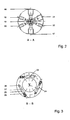
- FIG. 3 Exemplary is in Fig. 3 the front shaft part is shown in section B - B.
- the shaft 3 is arranged eccentrically and symmetrically distributed in this embodiment with three cooling circuit loops 23, 24 and 25. All three cooling loops 23, 24 and 25 are designed with a forward-parallel axis-parallel bore 26 and with a same adjacent second return bore 28. These two holes 26 and 28 are connected to each other in the foremost wave region with a transverse bore 27 closed on one side, which represents a cooling loop in the cooling circuit 7.
- Fig. 4 shows in a sectional view of the cooling system in the front part of the lance 4.
- a conveyed by a refrigerator and tempered cooling medium, such as water enriched with chemical durability additives is fed under pressure to the terminal 5 of the standing, screwed onto the rear spindle flange lance 4.
- the cooling medium is first brought into the transfer area 30 by two bores 29 running in parallel. The radial transfer takes place at the end of the holes 29 in a coextensive bore 31, perpendicular to the longitudinal axis.
- the now emerging from the stationary part of cooling water passes over the resulting between the lip seals 33 circulation in the three distributed through 120 ° feed holes 26 (see Fig. 3 ) of the shaft 3.
- the pressure exiting coolant increases the sealing behavior of the outside sealing lip seals 33 against the rotating shaft inner contour.
- this undergoes an additional acceleration due to the centrifugal force by the rotating shaft 3.
- the exploitation of this physical property is the key to realizing the media transfer from the static to the dynamic part.
- the cooling medium in the supply bores 31 passes over the reversing loops (transverse bores 27 (FIG. Fig. 3 In the region of the lance 4, the radial transfer from the rotating part takes place in the stationary part by the cooling medium over two revolutions 37, 38 in two perpendicular to the longitudinal axis bores 31, 32 in two parallel running Return bores 34 passes.
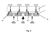
- the claimed in dependent claim 9 sealing symmetry of the lip seals 33 is shown. Between the rotating shaft 3 and the standing lance 4, the lip seals 33 are attached to the lance 4. The two outer lip seals 33 are subjected to a lower pressure (1 bar) than the two inner lip seals 33 (3 bar). Due to the flow and return pressures occurring in the example, different differential pressures, which are set on the outside sealing lips 33. By this symmetrical arrangement, the higher-stressed inner lip seals 33 are lubricated and cooled, which leads to an increase in the life.
- the Fig. 6 shows the guidance of the cone cleaning air and the sealing air in the tool motor spindle.
- the cone cleaning air is fed via the connection 44 of the lance 4 provided with a central bore 41. This serves for blowing out the tool cone and is only switched on when the spindle is stationary.
- the cone cleaning piston 43 With a rotating spindle, the cone cleaning piston 43 is lifted by the compression spring 42 from the rotating sealing surface of the shaft 3. At standstill, the cone cleaning air pressure can move the piston 43 forward to expose the passage of air in the cone cleaning hole 39 of the shaft 3.
- the sealing air 45, fed to the port 46 serves to seal the lance 4 from the outside. Due to their different chemical composition, the two leakage media (cooling medium and cooling lubricant) must be separated with the help of the sealing air.
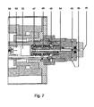
- the leakage guide and the internal cavity cooling are in Fig. 7 shown.
- the escape of the cooling water return flow escaping through the outer lip seals 33 accumulates in the region of the revolutions 47 and 48.
- the radial recirculation of the leakage takes place through the two transverse bores which open perpendicularly into the axial leakage bore 49.
- the leakage of the cooling water is finally returned via the connection 50 in the cooling unit.
- Via port 51 cooling lubricant is fed into the mold interior cooling system. This is passed through the standing lance 4 to the stationary part 52 of an existing built rotary union.
- the cooling lubricant is finally passed through the rotating part 53 of this rotary feedthrough through the remaining shaft part forward to the tool interface via the bore 56.
- Escaping, or back-dammed coolant from the rotary feedthrough is passed as leakage over the axially extending leakage bore 54 to the rear and out of the lance 4 via the connection 55.
- the Fig. 8 shows an exemplary variant of the shaft cooling.
- This wave cooling is contrary to Fig. 7 , which shows an inner rotary input 52, 53, an outer rotary feeder 57 on.
- This rotary feeder 57 is interchangeable without removing the whole lance 4.
- the sealing air separation between the internal cooling medium and the wave cooling medium is eliminated.
- the reference numeral 58 denotes the internal tool cooling.
- the purpose and the resulting benefits of cooling the rotating shaft is on the one hand to have a "cool wave", which limits the growth in length caused by temperature increase to a minimum. This leads to increased machining quality of each machining center where this inventive motor spindle is installed.
- the second advantage of this reduced longitudinal growth of the shaft, or the tool holder relative to the spindle nose is an increased accuracy of measurement when measuring workpieces. This allows the insertion of 3-D buttons into the "cool" tool interface, without the sensitive probe would grow by a too hot wave, resulting in highly accurate measurement results. Due to the lower temperature difference between the shaft and the bearing housing, the bearings can be designed with a narrower tolerance band, which leads to higher rigidity in operation and to an increased service life of the motor spindle.
Landscapes
- Engineering & Computer Science (AREA)
- Power Engineering (AREA)
- Mechanical Engineering (AREA)
- Auxiliary Devices For Machine Tools (AREA)
- Motor Or Generator Cooling System (AREA)
- Turning (AREA)
Description
- Die Erfindung betrifft eine Wellenkühlung für eine Werkzeug-Motorspindel mit einer rotierenden Welle, einer statischen Lanze und mindestens einem einen Kühlmitteleingang und einen Kühlmittelausgang aufweisenden Kühlkreislauf, wobei die Wellenkühlung derart ausgebildet ist, dass die Einbringung des Kühlmediums in der statischen Lanze von innen nach aussen in die rotierende Welle über Kühlbohrungen erfolgt.
- Die Werkzeug-Motorspindeln werden mit hohen Drehzahlen betrieben. Diese hohen Drehzahlen stellen an die Lageranordnung, über die die Spindel in dem Spindelgehäuse um ihre Spindelachse drehbar gelagert ist, hohe Anforderungen. Insbesondere muss die Lagerreibung auf ein absolutes Minimum reduziert werden, um Wärmeentwicklung und Verschleiss zu reduzieren. Daher ist es erforderlich eine Wellenkühlung vorzusehen.
- Die
EP 0 458 499 A2 beschreibt eine derartige Wellenkühlung für eine Werkzeug-Motorspindel mit einer rotierenden Welle, einer statischen Lanze und mindestens einem Kühlmitteleingang und einem Kühlmittelausgang aufweisenden Kühlkreislauf. Die Einbringung des Kühlmediums in der statischen Lanze erfolgt von innen nach aussen in die rotierende Welle über Kühlbohrungen. - Eine derartige Wellenkühlung ist in der
WO 2006/018394 A1 beschrieben. Hier wird eine Spindelvorrichtung mit einer Welleneinrichtung und einer Kühleinrichtung beschrieben. Die Kühleinrichtung weist mindestens einen Konvektionsspalt, über den gezielt ein wesentlicher Teil an Verlustwärme von der Welleneinrichtung abführbar ist. - Weiterhin sind Werkzeug-Motorspindeln bekannt, die zur Abführung der Verlustleistung aussengekühlt sind.
- Die an diesen bekannten Wellenkühlungen bestehenden Nachteile bestehen insbesondere darin, dass infolge der nicht genügenden Kühlwirkung ein aufgrund der Wärmeausdehnung nicht genügend reduziertes Wellenwachstum entsteht.
- Somit besteht die Aufgabe der Erfindung darin, eine Wellenkühlung vorzuschlagen, die einerseits ein Längenwachstum der Welle auf ein Minimum reduziert und andererseits aufgrund des geringen Längenwachstums eine hohe Messgenauigkeit beim Ausmessen des Werkstückes gewährleistet.
- Erfindungsgemäss wird diese Aufgabe dadurch gelöst, dass mehrere Lippendichtungen aussen dichtend an der stehenden, das Kühlmedium liefernden Lanze angeordnet sind und den Vor- und Rücklauf des Kühlmediums zwischen der Welle und der Lanze von einander abgrenzt.
- In den folgenden Zeichnungen ist ein erfindungsgemässes Ausführungsbeispiel dargestellt. Es zeigen:
-
Fig. 1 eine Schnittzeichnung einer wellengekühlten Werkzeug-Motorspindel, -
Fig. 2 eine Schnittdarstellung A - A des hinteren Teils der Lanze, -
Fig. 3 eine Schnittdarstellung B - B des vorderen Teils der Welle, -
Fig. 4 eine Schnittzeichnung des vorderen Lanzenteils, -
Fig. 5 eine Schnittzeichnung der Lippendichtungen, -
Fig. 6 eine Schnittzeichnung zur Darstellung der Werkzeugkonus-Reinigung und der Sperrluft, -
Fig. 7 eine Schnittzeichnung der Leckagen/Werkzeuginnenkühlung mit innenliegender Drehdurchführung und -
Fig. 8 eine Schnittzeichnung der Leckagen/Werkzeuginnenkühlung mit aussenliegender Drehdurchführung. - Die
Fig. 1 zeigt eine Werkzeug-Motorspindel 2 in Schnittansicht. Ein in einer Spindelhülse eingelassener Stator 9, in der Regel eine 3-phasige Motorwicklung, treibt einen auf einer durchgehenden Welle 3 angebrachten Rotor an. Die Welle 3 ist als Hohlwelle ausgebildet und mehrfach in einer Spindelhülse über ein vorderes 11 und ein hinteres 12 Lager gelagert. Weiterhin ist die Welle 3 mit einer mitdrehenden Spannvorrichtung, bestehend aus einem Werkzeugspanner 15 und einer Spannzange 10, ausgerüstet und in der Wellenbohrung 14 eingebracht. Diese Spannvorrichtung dient zum Einspannen eines Bearbeitungswerkzeuges mittels einer Spannzange 10. Das in der Figur nicht dargestellte Bearbeitungswerkzeug wird über einen Motor in Drehung versetzt. Durch die Bohrung 13 des Werkzeugspanners 15 wird einerseits Kühlmittel zur Innenkühlung des Werkzeugs geführt, andererseits wird durch die Welle 3 auch Druckluft zur Reinigung der Werkzeugschnittstelle geleitet. Die Welle 3 weist Kühlbohrungen 8 auf, die Bestandteile der Wellenkühlung 1 darstellen. - Durch die mit einer Zentralbohrung 41 ausgestatteten Lanze 4 werden sämtliche erwähnten Medien in die rotierende Welle 3 eingebracht. Das Kühlmedium wird zu Beginn des Kühlkreislaufs 7 in den Kühlmitteleingang 5 eingeleitet und tritt nach der Kühlung aus dem Kühlmittelausgang 6 aus.
- Der Schnitt A - A von
Fig. 1 ist inFig. 2 dargestellt. In diesem Beispiel werden vier Medien eingespiesen oder abgezogen. Mit 16 wird der Kühlmittelvorlauf und mit 17 der Kühlmittelrücklauf bezeichnet. Die Kühlmittelleckage wird über den Anschluss 18 abgezogen. Die Anschlüsse 19 und 20 dienen der Zuführung der Werkzeuginnenkühlung (Kühlschmiermittel) bzw. der Abführung der Leckage des Kühlschmiermittels. Die Kegelreinigungsluft wird in den Eingang 21 zugeführt. Zur Abdichtung des Systems wird über die Leitung 22 die Sperrluft eingespiesen. - Beispielhaft ist in
Fig. 3 der vordere Wellenteil im Schnitt B - B gezeigt. Die Welle 3 ist in dieser Ausführungsform mit drei Kühlkreislaufschlaufen 23, 24 und 25 aussermittig und symmetrisch verteilt angeordnet. Alle drei Kühlschlaufen 23, 24 und 25 sind mit einer nach vorne laufenden achsparallelen Bohrung 26 und mit einer gleichen daneben liegenden zweiten Rückführbohrung 28 ausgeführt. Diese beiden Bohrungen 26 und 28 sind im vordersten Wellenbereich mit einer einseitig verschlossenen Querbohrung 27 miteinander verbunden, was eine Kühlschlaufe im Kühlkreislauf 7 darstellt. -
Fig. 4 zeigt in Schnittansicht das Kühlsystem im vorderen Teil der Lanze 4. Ein von einem Kühlgerät gefördertes und temperiertes Kühlmedium, beispielsweise Wasser angereichert mit chemischen Haltbarkeitszusätzen, wird unter Druck an den Anschluss 5 der stehenden, auf den hinteren Spindelflansch aufgeschraubten Lanze 4 eingespiesen. Das Kühlmedium wird zuerst durch zwei parallel laufende Bohrungen 29 in den Übergabebereich 30 gebracht. Die radiale Übergabe erfolgt am Ende der Bohrungen 29 in eine flächengleiche Bohrung 31, senkrecht zur Längsachse. Das nun aus dem stehenden Teil austretende Kühlwasser gelangt über den sich zwischen den Lippendichtungen 33 ergebenden Umlauf in die drei um 120° verteilten Vorlaufbohrungen 26 (sieheFig. 3 ) der Welle 3. Dabei verstärkt das unter Druck austretende Kühlmedium das Dichtverhalten der aussen dichtenden Lippendichtungen 33 gegenüber der rotierenden Welleninnenkontur. Im Bereich 30 der radialen Übergabe des Kühlmediums erfährt dieses infolge der Zentrifugalkraft durch die rotierende Welle 3 eine zusätzliche Beschleunigung. Die Ausnutzung dieser physikalischen Eigenschaft ist der Schlüssel zur Verwirklichung der Medienübergabe aus dem statischen in den dynamischen Teil. Das Kühlmedium in den Vorlaufbohrungen 31 gelangt über die Umkehrschlaufen (Querbohrungen 27 (Fig. 3 ) im vordersten Wellenteil) in die Rücklaufbohrungen 32. Im Bereich der Lanze 4 erfolgt die radiale Übergabe vom rotierenden Teil in den stehenden Teil, indem das Kühlmedium über zwei Umläufe 37, 38 in zwei senkrecht zur Längsachse liegenden Bohrungen 31, 32 in zwei parallel laufende Rücklaufbohrungen 34 gelangt. Der Einbau der Lippendichtungen 33 ergibt für den Rücklauf naturgemäss eine unterschiedliche Anordnung, mit einer theoretisch höheren Leckage an der der Druckkammer abgewandten Dichtung. Um dem vorzubeugen sind in diesem Beispiel zwei radiale Übergaben zwecks Druckhalbierung des ohnehin reduzierten Rückführdruckes vorgesehen. Diese symmetrische Dichtungsanordnung (Hochdruckzuführung beidseitig umschlossen mit zwei Niederdruckrückführungen) dient der zusätzlichen Benetzung der Dichtflächen der nach innen gewandten Lippendichtungen 33. Dies führt infolge der Schmierwirkung zu einer erhöhten Lebensdauer der unter höherem Druck stehenden Vorlaufdichtungen, wie unten inFig. 5 beschrieben. Das Leckagekühlmedium wird über die Umläufe 35 und über eine eigene Rückführung aus der Lanze 4 gebracht. Die Leckage des Kühlmittels gelangt in den Umlauf 36. Die Rückführung des Kühlmediums in das Kühlgerät erfolgt schliesslich über den Anschluss 6. - In der
Fig. 5 wird die im Unteranspruch 9 beanspruchte Dichtungssymmetrie der Lippendichtungen 33 dargestellt. Zwischen der rotierenden Welle 3 und der stehenden Lanze 4 sind an der Lanze 4 die Lippendichtungen 33 angebracht. Die beiden äusseren Lippendichtungen 33 werden mit einem niedrigeren Druck (1 bar) als die beiden inneren Lippendichtungen 33 (3 bar) beaufschlagt. Durch die im Beispiel auftretenden Vor- und Rücklaufdrücke ergeben sich unterschiedliche Differenzdrücke, welche sich an den aussen dichtenden Lippen 33 einstellen. Durch diese symmetrische Anordnung werden die höher beanspruchten innen liegenden Lippendichtungen 33 geschmiert und gekühlt, was zu einer Erhöhung der Lebensdauer führt. - Die
Fig. 6 zeigt die Führung der Kegelreinigungsluft sowie der Sperrluft in der Werkzeug-Motorspindel. Die Kegelreinigungsluft wird über den Anschluss 44 der mit einer Zentralbohrung 41 versehenen Lanze 4 eingespiesen. Diese dient für das Ausblasen des Werkzeugkonus und wird nur bei still stehender Spindel eingeschaltet. Bei rotierender Spindel wird der Kegelreinigungskolben 43 durch die Druckfeder 42 von der rotierenden Dichtfläche der Welle 3 abgehoben. Im Stillstand vermag der Kegelreinigungsluftdruck den Kolben 43 nach vorne zu bewegen, um der Luft die Passage in die Kegelreinigungsbohrung 39 der Welle 3 freizulegen. Die Sperrluft 45, eingespiesen an den Anschluss 46 dient der Abdichtung der Lanze 4 gegenüber den Aussenbereichen. Die beiden Leckagemedien (Kühlmedium und Kühlschmiermittel) sind wegen ihrer unterschiedlicher chemischen Zusammensetzung mit Hilfe der Sperrluft zu trennen. Die radiale Übergabe der Sperrluft erfolgt am Ende der Bohrung 40 über den Umlauf und die kleine Bohrung nach beiden Seiten der Welle 3. Dieser Überdruck sorgt dafür, dass einerseits kein Leckagekühlwasser in das Welleninnere gelangt und anderseits kein Leckagekühlschmiermittel in den Bereich der Lanze 4 eindringt. - Die Leckagenführung und die Werkzeuginnenkühlung sind in
Fig. 7 gezeigt. Die durch die äusseren Lippendichtungen 33 entweichende Leckage des Kühlwasserrückflusses sammelt sich im Bereich der Umläufe 47 und 48. Die radiale Rückführung der Leckage erfolgt durch die zwei Querbohrungen, welche senkrecht in die axiale Leckagebohrung 49 münden.
Die Leckage des Kühlwassers wird schliesslich über den Anschluss 50 in das Kühlgerät zurückgeführt.
Über den Anschluss 51 wird Kühlschmiermittel für die Werkzeuginnenkühlung eingespiesen. Dieses wird durch die stehende Lanze 4 an den stehenden Teil 52 einer bereits vorhandenen eingebauten Drehdurchführung übergeben. Das Kühlschmiermittel wird schliesslich durch den rotieren Teil 53 dieser Drehdurchführung durch den restlichen Wellenteil nach vorne zur Werkzeugschnittstelle über die Bohrung 56 geleitet. - Austretendes, bzw. rückgestautes Kühlschmiermittel aus der Drehdurchführung wird als Leckage über die axial verlaufende Leckagebohrung 54 nach hinten geleitet und über den Anschluss 55 aus der Lanze 4 geführt.
- Die
Fig. 8 zeigt eine beispielhafte Variante der Wellenkühlung. Diese Wellenkühlung weist im Gegensatz zuFig. 7 , die eine innere Dreheinführung 52, 53 zeigt, eine äussere Drehzuführung 57 auf. Diese Drehzuführung 57 ist ohne Ausbau der ganzen Lanze 4 auswechselbar. Die Sperrluftabtrennung zwischen dem Innenkühlmedium und dem Wellenkühlmedium entfällt. Mit der Bezugszahl 58 ist die Werkzeuginnenkühlung bezeichnet. - Der Zweck und die daraus resultierenden Vorteile der Kühlung der rotierenden Welle ist einerseits eine "kühle Welle" zu haben, was das unter Temperaturzuwachs entstehende Längenwachstum auf ein Minimum begrenzt. Dies führt zu gesteigerter Bearbeitungsqualität eines jeden Bearbeitungszentrums, wo diese erfindungsgemässe Motorspindel eingebaut ist. Der zweite Vorteil dieses reduzierten Längenwachstums der Welle, bzw. der Werkzeugaufnahme gegenüber der Spindelnase ist eine gesteigerte Messgenauigkeit beim Ausmessen von Werkstücken. Dies ermöglicht das Einsetzen von 3-D Tastern in die "kühle" Werkzeugschnittstelle, ohne dass der empfindliche Messtaster durch eine zu warme Welle mitwachsen würde, was zu hoch genauen Messergebnissen führt. Auf Grund der geringeren Temperaturdifferenz zwischen Welle und Lagergehäuse lassen sich die Lager mit einem engeren Toleranzband auslegen, was zu höherer Steifigkeit im Betrieb und zu einer gesteigerten Lebensdauer der Motorspindel führt.
-
- 1
- Wellenkühlung
- 2
- Werkzeug-Motorspindel
- 3
- Welle
- 4
- Lanze
- 5
- Kühlmitteleingang
- 6
- Kühlmittelausgang
- 7
- Kühlkreislauf
- 8
- Kühlbohrungen
- 9
- Stator
- 10
- Spannzange
- 11
- vorderes Lager
- 12
- hinteres Lager
- 13
- Zentralbohrung
- 14
- Wellenbohrung
- 15
- Werkzeugspanner
- 16
- Kühlmittelvorlauf
- 17
- Kühlmittelrücklauf
- 18
- Kühlmittelleckage
- 19
- Werkzeuginnenkühlung
- 20
- Leckage für Werkzeuginnenkühlung
- 21
- Werkzeugreinigungsfuft
- 22
- Sperrluft
- 23
- Kühlkreislaufschlaufe
- 24
- Kühlkreislaufschlaufe
- 25
- Kühlkreislaufschlaufe
- 26
- Bohrung für Vorlauf
- 27
- Querbohrung
- 28
- Bohrung für Rücklauf
- 29
- Bohrung
- 30
- Übergabebereich
- 31
- Bohrung
- 32
- Rücklaufbohrung
- 33
- Lippendichtung
- 34
- Rücklaufbohrung
- 35
- Leckage Kühlwasser
- 36
- Leckage Kühlmittel
- 37
- Bohrung
- 38
- Rücklauf
- 39
- Kegelreinigungsbohrung
- 40
- Bohrung
- 41
- Zentralbohrung
- 42
- Druckfeder
- 43
- Kolben
- 44
- Einspeisung Kegelreinigung
- 45
- Einspeisung Sperrluft
- 46
- Anschluss
- 47
- Umlauf
- 48
- Umlauf
- 49
- Leckagebohrung Kühlwasser
- 50
- Anschluss
- 51
- Anschluss
- 52
- Drehdurchführung
- 53
- Drehdurchführung
- 54
- Leckagebohrung
- 55
- Anschluss
- 56
- Bohrung
- 57
- Drehzuführung
- 58
- Werkzeuginnenkühlung
Claims (8)
- Wellenkühlung (1) für eine Werkzeug-Motorspindel (2) mit einer rotierenden Welle (3), einer statischen Lanze (4) und mindestens einem einen Kühlmitteleingang (5) und einen Kühlmittelausgang (6) aufweisenden Kühlkreislauf (7), wobei die Wellenkühlung (1) derart ausgebildet ist, dass die Einbringung des Kühlmediums in der statischen Lanze (4) von innen nach aussen in die rotierende Welle (3) über Kühlbohrungen (8) erfolgt dadurch gekennzeichnet, dass mehrere Lippendichtungen (33) aussen dichtend an der stehenden, das Kühlmedium liefernden Lanze (4) angeordnet sind und den Vor- und Rücklauf des Kühlmediums zwischen der Welle (3) und der Lanze (4) von einander abgrenzt.
- Wellenkühlung nach Anspruch 1, dadurch gekennzeichnet, dass die feststehende Lanze (4) eine durchgehende Zentralbohrung (13, 41) aufweist.
- Wellenkühlung nach Anspruch 1 oder 2, dadurch gekennzeichnet, dass die Welle (3) durch mehrere Kühlbohrungen (8) mit dem Kühlmedium kühlbar ist.
- Wellenkühlung nach mindestens einem der Ansprüche 1, 2 oder 3, dadurch gekennzeichnet, dass in die Lanze (4) mehrere Medien einspeisbar sind.
- Wellenkühlung nach mindestens einem der vorherigen Ansprüche, dadurch gekennzeichnet, dass das System mittels Sperrluft (22, 45) abdichtbar ist.
- Wellenkühlung nach mindestens einem der vorherigen Ansprüche, dadurch gekennzeichnet, dass der Kühlkreislauf (7) mehrere Kreislaufschlaufen (23, 24, 25) aufweist.
- Wellenkühlung nach mindestens einem der vorherigen Ansprüche, dadurch gekennzeichnet, dass das Kühlmittel infolge der rotierenden Welle (3) mit einer Zentrifugalkraft beaufschlagbar und somit nach aussen transportierbar ist.
- Wellenkühlung nach mindestens einem der vorherigen Ansprüche, dadurch gekennzeichnet, dass die Lippendichtungen (33) symmetrisch angeordnet sind.
Priority Applications (6)
| Application Number | Priority Date | Filing Date | Title |
|---|---|---|---|
| AT07120261T ATE504391T1 (de) | 2007-11-08 | 2007-11-08 | Wellenkühlung für eine werkzeug-motorspindel |
| EP07120261A EP2058085B1 (de) | 2007-11-08 | 2007-11-08 | Wellenkühlung für eine Werkzeug-Motorspindel |
| DE502007006895T DE502007006895D1 (de) | 2007-11-08 | 2007-11-08 | Wellenkühlung für eine Werkzeug-Motorspindel |
| CN200880115744.0A CN101855043B (zh) | 2007-11-08 | 2008-11-04 | 用于工具马达芯轴的轴冷却器 |
| US12/741,866 US8684643B2 (en) | 2007-11-08 | 2008-11-04 | Shaft cooler for a tool motor spindle |
| PCT/EP2008/064900 WO2009059954A1 (de) | 2007-11-08 | 2008-11-04 | Wellenkühlung für eine werkzeug-motorspindel |
Applications Claiming Priority (1)
| Application Number | Priority Date | Filing Date | Title |
|---|---|---|---|
| EP07120261A EP2058085B1 (de) | 2007-11-08 | 2007-11-08 | Wellenkühlung für eine Werkzeug-Motorspindel |
Publications (2)
| Publication Number | Publication Date |
|---|---|
| EP2058085A1 EP2058085A1 (de) | 2009-05-13 |
| EP2058085B1 true EP2058085B1 (de) | 2011-04-06 |
Family
ID=38980916
Family Applications (1)
| Application Number | Title | Priority Date | Filing Date |
|---|---|---|---|
| EP07120261A Active EP2058085B1 (de) | 2007-11-08 | 2007-11-08 | Wellenkühlung für eine Werkzeug-Motorspindel |
Country Status (6)
| Country | Link |
|---|---|
| US (1) | US8684643B2 (de) |
| EP (1) | EP2058085B1 (de) |
| CN (1) | CN101855043B (de) |
| AT (1) | ATE504391T1 (de) |
| DE (1) | DE502007006895D1 (de) |
| WO (1) | WO2009059954A1 (de) |
Cited By (1)
| Publication number | Priority date | Publication date | Assignee | Title |
|---|---|---|---|---|
| DE102020120038A1 (de) | 2020-07-29 | 2022-02-03 | Technische Hochschule Köln | Temperieren eines Maschinenmoduls |
Families Citing this family (12)
| Publication number | Priority date | Publication date | Assignee | Title |
|---|---|---|---|---|
| DE102013104711A1 (de) * | 2013-05-07 | 2014-11-13 | Dr. Ing. H.C. F. Porsche Aktiengesellschaft | Elektrische Maschine mit gekühlter Rotorwelle |
| DE102016114036A1 (de) * | 2016-07-29 | 2018-02-01 | Ott-Jakob Spanntechnik Gmbh | Arbeitsspindel-Kühleinrichtung und Werkzeugmaschinen-Bearbeitungseinheit mit einer derartigen Arbeitspindel-Kühleinrichtung |
| CN106549531B (zh) * | 2017-01-13 | 2023-08-18 | 广东华顺电机科技有限公司 | 带轴通水的自动补偿进级量的抛光电机 |
| CN107009193A (zh) * | 2017-05-22 | 2017-08-04 | 北京精雕科技集团有限公司 | 一种具有转子冷却的电主轴 |
| DE102017211318B4 (de) | 2017-07-04 | 2020-08-20 | Audi Ag | Elektrische Maschine |
| EP3444686B1 (de) * | 2017-08-15 | 2021-12-22 | GF Machining Solutions AG | Verfahren zur verwendung einer geometrischen sonde mit einer spindel einer werkzeugmaschine und werkzeugmaschine mit konfiguration zur durchführung solch eines verfahrens |
| DE102017129212A1 (de) * | 2017-12-08 | 2019-06-13 | Dr. Ing. H.C. F. Porsche Aktiengesellschaft | Rotor mit Kühlung |
| CN108087092A (zh) * | 2017-12-12 | 2018-05-29 | 严传玉 | 一种高效散热的发动机 |
| DE102018218815A1 (de) * | 2018-11-05 | 2020-05-07 | Zf Friedrichshafen Ag | Elektrische Maschine mit einer Fluid-Kühleinrichtung |
| EP4153378A4 (de) * | 2020-05-21 | 2024-05-29 | Coventry Associates, Inc. | Hochpräzise temperatur- und kontaminationskontrolle zur genauen positionierung einer werkzeugmaschine |
| CN112405105B (zh) * | 2021-01-25 | 2021-05-18 | 常州德匠数控科技有限公司 | 一种能够均匀冷却的主轴及工作方法 |
| EP4454807A3 (de) * | 2024-09-13 | 2025-03-26 | Maschinenfabrik Berthold Hermle AG | Motorspindel |
Family Cites Families (27)
| Publication number | Priority date | Publication date | Assignee | Title |
|---|---|---|---|---|
| US3240967A (en) * | 1959-07-31 | 1966-03-15 | Krastchew Christoslaw | Cooling arrangement for electric machines |
| JPS4925561B1 (de) * | 1968-11-25 | 1974-07-02 | ||
| BE789009A (fr) * | 1971-09-21 | 1973-03-20 | Westinghouse Electric Corp | Rotor refroidi par liquide pour machines dynamoelectriques |
| US4114058A (en) * | 1976-09-03 | 1978-09-12 | Westinghouse Electric Corp. | Seal arrangement for a discharge chamber for water cooled turbine generator rotor |
| JPS6377636A (ja) * | 1986-09-19 | 1988-04-07 | Hitachi Seiko Ltd | 工作機械の主軸装置 |
| JPH07106534B2 (ja) * | 1987-09-29 | 1995-11-15 | 株式会社牧野フライス製作所 | 主軸内に冷却液を流通させた主軸装置 |
| DE3838318A1 (de) * | 1988-11-11 | 1990-05-17 | Krupp Widia Gmbh | Werkzeugsystem |
| US5145298A (en) * | 1989-09-11 | 1992-09-08 | Optima Industries, Inc. | High speed drill spindle |
| DE69126917T2 (de) | 1990-05-21 | 1998-03-05 | Makino Milling Machine | Kühlapparat eines Maschinenspindellagers |
| US5651645A (en) * | 1994-10-12 | 1997-07-29 | Walter W. Wawrzyniak | Generating head assembly with generating head and rotary power actuator |
| DE19538762C1 (de) * | 1995-10-18 | 1997-04-10 | Hueller Hille Gmbh | Verfahren zur Kühlung und Schmierung eines spanend arbeitenden, rotierenden Werkzeuges mit geometrisch definierter Schneide und/oder des Werkstückes im Bearbeitungsbereich u. Bearbeitungsspindel zur Durchführung des Verfahrens |
| DE19543612C1 (de) * | 1995-11-23 | 1997-05-07 | Glyco Antriebstechnik Gmbh | Spannvorrichtung mit integrierter Fluid-Drehdurchführung |
| JP3773316B2 (ja) * | 1996-07-18 | 2006-05-10 | 森精機興産株式会社 | 工作機械における切削油剤による主軸装置の冷却方法及び主軸冷却装置 |
| US5672035A (en) * | 1996-09-16 | 1997-09-30 | Chrysler Corporation | Turn broaching machine |
| SE519206C2 (sv) * | 1999-03-23 | 2003-01-28 | Lind Finance & Dev Ab | Anordning vid verktygsspindel försedd med en rotor varvid anordningen innefattar medel för kylning av rotorn |
| JP2001310210A (ja) * | 2000-04-25 | 2001-11-06 | Toshiba Mach Co Ltd | 繰り出し軸冷却装置 |
| JP4809521B2 (ja) * | 2000-09-19 | 2011-11-09 | マンヨーツール株式会社 | 工具ホルダ及びその冷却装置 |
| US6398468B1 (en) * | 2001-01-19 | 2002-06-04 | Bayer Machine Tech Llc | Machine tool quill spindle |
| US6715971B2 (en) * | 2001-04-09 | 2004-04-06 | Gary L. Curtis | Automated coolant delivery method and system for a machine tool |
| JP2003042392A (ja) * | 2001-07-27 | 2003-02-13 | I M N Kk | 回転部支持体における潤滑油供給方法 |
| DE20205861U1 (de) * | 2002-04-03 | 2002-09-19 | TBT Tiefbohrtechnik GmbH, 72581 Dettingen | Bohreinrichtung mit einem mehrschneidigen Bohrwerkzeug, insbesondere Tiefbohrwerkzeug |
| SE522478C2 (sv) * | 2002-06-17 | 2004-02-10 | Sandvik Ab | Gasfjäder, ingående i en fastspänningsanordning vid en maskinspindel |
| DE102004039412A1 (de) | 2004-08-13 | 2006-03-02 | Siemens Ag | Spindelvorrichtung und entsprechendes Verfahren zu deren Kühlung |
| DE102005030277B4 (de) * | 2005-06-21 | 2007-10-31 | Fischer AG Präzisionsspindeln | Spindelvorrichtung mit Innenkühlung |
| SE531738C2 (sv) * | 2006-09-01 | 2009-07-28 | Husqvarna Ab | Borrmaskin |
| US7287941B1 (en) * | 2006-09-05 | 2007-10-30 | Kennametal Inc. | Apparatus for amplifying the pull back force on a lock rod used to secure a toolholder |
| JP5690613B2 (ja) * | 2011-02-25 | 2015-03-25 | オークマ株式会社 | 主軸装置 |
-
2007
- 2007-11-08 EP EP07120261A patent/EP2058085B1/de active Active
- 2007-11-08 DE DE502007006895T patent/DE502007006895D1/de active Active
- 2007-11-08 AT AT07120261T patent/ATE504391T1/de active
-
2008
- 2008-11-04 CN CN200880115744.0A patent/CN101855043B/zh active Active
- 2008-11-04 WO PCT/EP2008/064900 patent/WO2009059954A1/de not_active Ceased
- 2008-11-04 US US12/741,866 patent/US8684643B2/en active Active
Cited By (2)
| Publication number | Priority date | Publication date | Assignee | Title |
|---|---|---|---|---|
| DE102020120038A1 (de) | 2020-07-29 | 2022-02-03 | Technische Hochschule Köln | Temperieren eines Maschinenmoduls |
| DE102020120038B4 (de) | 2020-07-29 | 2024-10-31 | Technische Hochschule Köln | Verfahren zum Betreiben einer Temperiervorrichtung |
Also Published As
| Publication number | Publication date |
|---|---|
| EP2058085A1 (de) | 2009-05-13 |
| ATE504391T1 (de) | 2011-04-15 |
| DE502007006895D1 (de) | 2011-05-19 |
| US8684643B2 (en) | 2014-04-01 |
| US20100252236A1 (en) | 2010-10-07 |
| WO2009059954A1 (de) | 2009-05-14 |
| CN101855043B (zh) | 2014-05-14 |
| CN101855043A (zh) | 2010-10-06 |
Similar Documents
| Publication | Publication Date | Title |
|---|---|---|
| EP2058085B1 (de) | Wellenkühlung für eine Werkzeug-Motorspindel | |
| DE102005030277B4 (de) | Spindelvorrichtung mit Innenkühlung | |
| EP0840866B1 (de) | Drehdurchführung für hohe drücke und hohe relativgeschwindigkeiten | |
| DE69126917T2 (de) | Kühlapparat eines Maschinenspindellagers | |
| DE102011050662B4 (de) | Walzwerkzeug | |
| DE10105672B4 (de) | Spindelvorrichtung mit Turbinenrotor | |
| EP0498146A2 (de) | Drehdurchführung für zwei unterschiedliche Fluide | |
| DE1018696B (de) | Einrichtung zum Zufuehren von Druckfluessigkeit in rotierende, hydraulisch betaetigte Vorrichtungen | |
| DE2612983A1 (de) | Drehkolbenmaschine | |
| EP1514047B1 (de) | Drehdurchführung | |
| DE10242449A1 (de) | Werkzeugmaschinenspindel mit Gleitringdichtung | |
| EP0220558B1 (de) | Druckmittelverteiler für umlaufende Spannzylinder | |
| DE60013572T2 (de) | Vorrichtung für eine werkzeugspindel | |
| DE2417887A1 (de) | Rotationsfaehiger hydraulikzylinder, insbesondere zum betaetigen eines werkzeugmaschinen-spannfutters | |
| DE4226922B4 (de) | Spindelkopf mit Anordnung zur Versorgung mit Kühl- und/oder Schmiermittel | |
| DE60013567T2 (de) | Einrichtung einer werkzeugspindel | |
| DE102017206686B4 (de) | Lageranordnung zur Lagerung einer Getriebewelle | |
| DE19960907C1 (de) | Drehverteiler zur Übertragung eines Fluids | |
| DE3243112A1 (de) | Durchflusssteuereinrichtung fuer gas- und fluessigmedien in einer werkzeugmaschinenarbeitsspindel | |
| DE4003663C2 (de) | Rotationskolbenbrennkraftmaschine mit gleitgelagertem, ölgekühltem Kolben | |
| DE60013571T2 (de) | Vorrichtung für eine werkzeugspindel | |
| DE2911000C2 (de) | Drehdurchführung für die Einleitung strömungsfähiger Medien in ein rotierendes Maschinenteil | |
| WO2023217734A1 (de) | Rotorbaugruppe für eine werkzeugspindel | |
| DE60013568T2 (de) | Vorrichtung für eine werkzeugspindel | |
| EP1758739B1 (de) | Zylinder für bahnförmiges material verarbeitende maschinen |
Legal Events
| Date | Code | Title | Description |
|---|---|---|---|
| PUAI | Public reference made under article 153(3) epc to a published international application that has entered the european phase |
Free format text: ORIGINAL CODE: 0009012 |
|
| AK | Designated contracting states |
Kind code of ref document: A1 Designated state(s): AT BE BG CH CY CZ DE DK EE ES FI FR GB GR HU IE IS IT LI LT LU LV MC MT NL PL PT RO SE SI SK TR |
|
| AX | Request for extension of the european patent |
Extension state: AL BA HR MK RS |
|
| 17P | Request for examination filed |
Effective date: 20090811 |
|
| 17Q | First examination report despatched |
Effective date: 20090907 |
|
| AKX | Designation fees paid |
Designated state(s): AT BE BG CH CY CZ DE DK EE ES FI FR GB GR HU IE IS IT LI LT LU LV MC MT NL PL PT RO SE SI SK TR |
|
| GRAP | Despatch of communication of intention to grant a patent |
Free format text: ORIGINAL CODE: EPIDOSNIGR1 |
|
| GRAS | Grant fee paid |
Free format text: ORIGINAL CODE: EPIDOSNIGR3 |
|
| GRAA | (expected) grant |
Free format text: ORIGINAL CODE: 0009210 |
|
| AK | Designated contracting states |
Kind code of ref document: B1 Designated state(s): AT BE BG CH CY CZ DE DK EE ES FI FR GB GR HU IE IS IT LI LT LU LV MC MT NL PL PT RO SE SI SK TR |
|
| REG | Reference to a national code |
Ref country code: GB Ref legal event code: FG4D Free format text: NOT ENGLISH |
|
| REG | Reference to a national code |
Ref country code: CH Ref legal event code: EP Ref country code: CH Ref legal event code: NV Representative=s name: GEORG FISCHER AG |
|
| REG | Reference to a national code |
Ref country code: IE Ref legal event code: FG4D |
|
| REF | Corresponds to: |
Ref document number: 502007006895 Country of ref document: DE Date of ref document: 20110519 Kind code of ref document: P |
|
| REG | Reference to a national code |
Ref country code: DE Ref legal event code: R096 Ref document number: 502007006895 Country of ref document: DE Effective date: 20110519 |
|
| REG | Reference to a national code |
Ref country code: NL Ref legal event code: VDEP Effective date: 20110406 |
|
| PG25 | Lapsed in a contracting state [announced via postgrant information from national office to epo] |
Ref country code: SI Free format text: LAPSE BECAUSE OF FAILURE TO SUBMIT A TRANSLATION OF THE DESCRIPTION OR TO PAY THE FEE WITHIN THE PRESCRIBED TIME-LIMIT Effective date: 20110406 |
|
| LTIE | Lt: invalidation of european patent or patent extension |
Effective date: 20110406 |
|
| REG | Reference to a national code |
Ref country code: IE Ref legal event code: FD4D |
|
| PG25 | Lapsed in a contracting state [announced via postgrant information from national office to epo] |
Ref country code: SE Free format text: LAPSE BECAUSE OF FAILURE TO SUBMIT A TRANSLATION OF THE DESCRIPTION OR TO PAY THE FEE WITHIN THE PRESCRIBED TIME-LIMIT Effective date: 20110406 Ref country code: LT Free format text: LAPSE BECAUSE OF FAILURE TO SUBMIT A TRANSLATION OF THE DESCRIPTION OR TO PAY THE FEE WITHIN THE PRESCRIBED TIME-LIMIT Effective date: 20110406 Ref country code: PT Free format text: LAPSE BECAUSE OF FAILURE TO SUBMIT A TRANSLATION OF THE DESCRIPTION OR TO PAY THE FEE WITHIN THE PRESCRIBED TIME-LIMIT Effective date: 20110808 |
|
| PG25 | Lapsed in a contracting state [announced via postgrant information from national office to epo] |
Ref country code: FI Free format text: LAPSE BECAUSE OF FAILURE TO SUBMIT A TRANSLATION OF THE DESCRIPTION OR TO PAY THE FEE WITHIN THE PRESCRIBED TIME-LIMIT Effective date: 20110406 Ref country code: CY Free format text: LAPSE BECAUSE OF FAILURE TO SUBMIT A TRANSLATION OF THE DESCRIPTION OR TO PAY THE FEE WITHIN THE PRESCRIBED TIME-LIMIT Effective date: 20110406 Ref country code: ES Free format text: LAPSE BECAUSE OF FAILURE TO SUBMIT A TRANSLATION OF THE DESCRIPTION OR TO PAY THE FEE WITHIN THE PRESCRIBED TIME-LIMIT Effective date: 20110717 Ref country code: LV Free format text: LAPSE BECAUSE OF FAILURE TO SUBMIT A TRANSLATION OF THE DESCRIPTION OR TO PAY THE FEE WITHIN THE PRESCRIBED TIME-LIMIT Effective date: 20110406 Ref country code: GR Free format text: LAPSE BECAUSE OF FAILURE TO SUBMIT A TRANSLATION OF THE DESCRIPTION OR TO PAY THE FEE WITHIN THE PRESCRIBED TIME-LIMIT Effective date: 20110707 Ref country code: IS Free format text: LAPSE BECAUSE OF FAILURE TO SUBMIT A TRANSLATION OF THE DESCRIPTION OR TO PAY THE FEE WITHIN THE PRESCRIBED TIME-LIMIT Effective date: 20110806 |
|
| PG25 | Lapsed in a contracting state [announced via postgrant information from national office to epo] |
Ref country code: NL Free format text: LAPSE BECAUSE OF FAILURE TO SUBMIT A TRANSLATION OF THE DESCRIPTION OR TO PAY THE FEE WITHIN THE PRESCRIBED TIME-LIMIT Effective date: 20110406 |
|
| PG25 | Lapsed in a contracting state [announced via postgrant information from national office to epo] |
Ref country code: CZ Free format text: LAPSE BECAUSE OF FAILURE TO SUBMIT A TRANSLATION OF THE DESCRIPTION OR TO PAY THE FEE WITHIN THE PRESCRIBED TIME-LIMIT Effective date: 20110406 Ref country code: EE Free format text: LAPSE BECAUSE OF FAILURE TO SUBMIT A TRANSLATION OF THE DESCRIPTION OR TO PAY THE FEE WITHIN THE PRESCRIBED TIME-LIMIT Effective date: 20110406 Ref country code: IE Free format text: LAPSE BECAUSE OF FAILURE TO SUBMIT A TRANSLATION OF THE DESCRIPTION OR TO PAY THE FEE WITHIN THE PRESCRIBED TIME-LIMIT Effective date: 20110406 |
|
| PLBE | No opposition filed within time limit |
Free format text: ORIGINAL CODE: 0009261 |
|
| STAA | Information on the status of an ep patent application or granted ep patent |
Free format text: STATUS: NO OPPOSITION FILED WITHIN TIME LIMIT |
|
| PG25 | Lapsed in a contracting state [announced via postgrant information from national office to epo] |
Ref country code: SK Free format text: LAPSE BECAUSE OF FAILURE TO SUBMIT A TRANSLATION OF THE DESCRIPTION OR TO PAY THE FEE WITHIN THE PRESCRIBED TIME-LIMIT Effective date: 20110406 Ref country code: PL Free format text: LAPSE BECAUSE OF FAILURE TO SUBMIT A TRANSLATION OF THE DESCRIPTION OR TO PAY THE FEE WITHIN THE PRESCRIBED TIME-LIMIT Effective date: 20110406 Ref country code: DK Free format text: LAPSE BECAUSE OF FAILURE TO SUBMIT A TRANSLATION OF THE DESCRIPTION OR TO PAY THE FEE WITHIN THE PRESCRIBED TIME-LIMIT Effective date: 20110406 Ref country code: RO Free format text: LAPSE BECAUSE OF FAILURE TO SUBMIT A TRANSLATION OF THE DESCRIPTION OR TO PAY THE FEE WITHIN THE PRESCRIBED TIME-LIMIT Effective date: 20110406 |
|
| 26N | No opposition filed |
Effective date: 20120110 |
|
| REG | Reference to a national code |
Ref country code: DE Ref legal event code: R097 Ref document number: 502007006895 Country of ref document: DE Effective date: 20120110 |
|
| BERE | Be: lapsed |
Owner name: STEP-TEC A.G. Effective date: 20111130 |
|
| PG25 | Lapsed in a contracting state [announced via postgrant information from national office to epo] |
Ref country code: MC Free format text: LAPSE BECAUSE OF NON-PAYMENT OF DUE FEES Effective date: 20111130 |
|
| GBPC | Gb: european patent ceased through non-payment of renewal fee |
Effective date: 20111108 |
|
| REG | Reference to a national code |
Ref country code: FR Ref legal event code: ST Effective date: 20120731 |
|
| PG25 | Lapsed in a contracting state [announced via postgrant information from national office to epo] |
Ref country code: BE Free format text: LAPSE BECAUSE OF NON-PAYMENT OF DUE FEES Effective date: 20111130 |
|
| PG25 | Lapsed in a contracting state [announced via postgrant information from national office to epo] |
Ref country code: GB Free format text: LAPSE BECAUSE OF NON-PAYMENT OF DUE FEES Effective date: 20111108 |
|
| PG25 | Lapsed in a contracting state [announced via postgrant information from national office to epo] |
Ref country code: FR Free format text: LAPSE BECAUSE OF NON-PAYMENT OF DUE FEES Effective date: 20111130 |
|
| PG25 | Lapsed in a contracting state [announced via postgrant information from national office to epo] |
Ref country code: MT Free format text: LAPSE BECAUSE OF FAILURE TO SUBMIT A TRANSLATION OF THE DESCRIPTION OR TO PAY THE FEE WITHIN THE PRESCRIBED TIME-LIMIT Effective date: 20110406 |
|
| PG25 | Lapsed in a contracting state [announced via postgrant information from national office to epo] |
Ref country code: LU Free format text: LAPSE BECAUSE OF NON-PAYMENT OF DUE FEES Effective date: 20111108 |
|
| PG25 | Lapsed in a contracting state [announced via postgrant information from national office to epo] |
Ref country code: BG Free format text: LAPSE BECAUSE OF FAILURE TO SUBMIT A TRANSLATION OF THE DESCRIPTION OR TO PAY THE FEE WITHIN THE PRESCRIBED TIME-LIMIT Effective date: 20110706 |
|
| PG25 | Lapsed in a contracting state [announced via postgrant information from national office to epo] |
Ref country code: TR Free format text: LAPSE BECAUSE OF FAILURE TO SUBMIT A TRANSLATION OF THE DESCRIPTION OR TO PAY THE FEE WITHIN THE PRESCRIBED TIME-LIMIT Effective date: 20110406 |
|
| PG25 | Lapsed in a contracting state [announced via postgrant information from national office to epo] |
Ref country code: HU Free format text: LAPSE BECAUSE OF FAILURE TO SUBMIT A TRANSLATION OF THE DESCRIPTION OR TO PAY THE FEE WITHIN THE PRESCRIBED TIME-LIMIT Effective date: 20110406 |
|
| REG | Reference to a national code |
Ref country code: AT Ref legal event code: MM01 Ref document number: 504391 Country of ref document: AT Kind code of ref document: T Effective date: 20121130 |
|
| PG25 | Lapsed in a contracting state [announced via postgrant information from national office to epo] |
Ref country code: AT Free format text: LAPSE BECAUSE OF NON-PAYMENT OF DUE FEES Effective date: 20121130 |
|
| REG | Reference to a national code |
Ref country code: CH Ref legal event code: PK Free format text: BERICHTIGUNG INHABER |
|
| PGFP | Annual fee paid to national office [announced via postgrant information from national office to epo] |
Ref country code: IT Payment date: 20201124 Year of fee payment: 14 |
|
| REG | Reference to a national code |
Ref country code: DE Ref legal event code: R081 Ref document number: 502007006895 Country of ref document: DE Owner name: GF MACHINING SOLUTIONS AG, CH Free format text: FORMER OWNER: STEP-TEC AG, LUTERBACH, CH |
|
| PG25 | Lapsed in a contracting state [announced via postgrant information from national office to epo] |
Ref country code: IT Free format text: LAPSE BECAUSE OF NON-PAYMENT OF DUE FEES Effective date: 20211130 |
|
| P01 | Opt-out of the competence of the unified patent court (upc) registered |
Effective date: 20230529 |
|
| REG | Reference to a national code |
Ref country code: DE Ref legal event code: R082 Ref document number: 502007006895 Country of ref document: DE Representative=s name: DENNEMEYER & ASSOCIATES RECHTSANWALTSGESELLSCH, DE |
|
| REG | Reference to a national code |
Ref country code: CH Ref legal event code: U11 Free format text: ST27 STATUS EVENT CODE: U-0-0-U10-U11 (AS PROVIDED BY THE NATIONAL OFFICE) Effective date: 20251201 |
|
| PGFP | Annual fee paid to national office [announced via postgrant information from national office to epo] |
Ref country code: DE Payment date: 20251119 Year of fee payment: 19 |
|
| PGFP | Annual fee paid to national office [announced via postgrant information from national office to epo] |
Ref country code: CH Payment date: 20251201 Year of fee payment: 19 |