EP1514047B1 - Drehdurchführung - Google Patents
Drehdurchführung Download PDFInfo
- Publication number
- EP1514047B1 EP1514047B1 EP03757020A EP03757020A EP1514047B1 EP 1514047 B1 EP1514047 B1 EP 1514047B1 EP 03757020 A EP03757020 A EP 03757020A EP 03757020 A EP03757020 A EP 03757020A EP 1514047 B1 EP1514047 B1 EP 1514047B1
- Authority
- EP
- European Patent Office
- Prior art keywords
- sealing
- housing part
- rotary feedthrough
- supply
- cooling lubricant
- Prior art date
- Legal status (The legal status is an assumption and is not a legal conclusion. Google has not performed a legal analysis and makes no representation as to the accuracy of the status listed.)
- Expired - Lifetime
Links
Images

Classifications
-
- F—MECHANICAL ENGINEERING; LIGHTING; HEATING; WEAPONS; BLASTING
- F16—ENGINEERING ELEMENTS AND UNITS; GENERAL MEASURES FOR PRODUCING AND MAINTAINING EFFECTIVE FUNCTIONING OF MACHINES OR INSTALLATIONS; THERMAL INSULATION IN GENERAL
- F16L—PIPES; JOINTS OR FITTINGS FOR PIPES; SUPPORTS FOR PIPES, CABLES OR PROTECTIVE TUBING; MEANS FOR THERMAL INSULATION IN GENERAL
- F16L27/00—Adjustable joints; Joints allowing movement
- F16L27/08—Adjustable joints; Joints allowing movement allowing adjustment or movement only about the axis of one pipe
- F16L27/0804—Adjustable joints; Joints allowing movement allowing adjustment or movement only about the axis of one pipe the fluid passing axially from one joint element to another
- F16L27/0808—Adjustable joints; Joints allowing movement allowing adjustment or movement only about the axis of one pipe the fluid passing axially from one joint element to another the joint elements extending coaxially for some distance from their point of separation
- F16L27/0812—Adjustable joints; Joints allowing movement allowing adjustment or movement only about the axis of one pipe the fluid passing axially from one joint element to another the joint elements extending coaxially for some distance from their point of separation with slide bearings
- F16L27/082—Adjustable joints; Joints allowing movement allowing adjustment or movement only about the axis of one pipe the fluid passing axially from one joint element to another the joint elements extending coaxially for some distance from their point of separation with slide bearings having axial sealing
-
- F—MECHANICAL ENGINEERING; LIGHTING; HEATING; WEAPONS; BLASTING
- F16—ENGINEERING ELEMENTS AND UNITS; GENERAL MEASURES FOR PRODUCING AND MAINTAINING EFFECTIVE FUNCTIONING OF MACHINES OR INSTALLATIONS; THERMAL INSULATION IN GENERAL
- F16L—PIPES; JOINTS OR FITTINGS FOR PIPES; SUPPORTS FOR PIPES, CABLES OR PROTECTIVE TUBING; MEANS FOR THERMAL INSULATION IN GENERAL
- F16L27/00—Adjustable joints; Joints allowing movement
- F16L27/08—Adjustable joints; Joints allowing movement allowing adjustment or movement only about the axis of one pipe
- F16L27/0804—Adjustable joints; Joints allowing movement allowing adjustment or movement only about the axis of one pipe the fluid passing axially from one joint element to another
- F16L27/0808—Adjustable joints; Joints allowing movement allowing adjustment or movement only about the axis of one pipe the fluid passing axially from one joint element to another the joint elements extending coaxially for some distance from their point of separation
- F16L27/0824—Adjustable joints; Joints allowing movement allowing adjustment or movement only about the axis of one pipe the fluid passing axially from one joint element to another the joint elements extending coaxially for some distance from their point of separation with ball or roller bearings
- F16L27/0828—Adjustable joints; Joints allowing movement allowing adjustment or movement only about the axis of one pipe the fluid passing axially from one joint element to another the joint elements extending coaxially for some distance from their point of separation with ball or roller bearings having radial bearings
-
- Y—GENERAL TAGGING OF NEW TECHNOLOGICAL DEVELOPMENTS; GENERAL TAGGING OF CROSS-SECTIONAL TECHNOLOGIES SPANNING OVER SEVERAL SECTIONS OF THE IPC; TECHNICAL SUBJECTS COVERED BY FORMER USPC CROSS-REFERENCE ART COLLECTIONS [XRACs] AND DIGESTS
- Y10—TECHNICAL SUBJECTS COVERED BY FORMER USPC
- Y10T—TECHNICAL SUBJECTS COVERED BY FORMER US CLASSIFICATION
- Y10T137/00—Fluid handling
- Y10T137/2496—Self-proportioning or correlating systems
- Y10T137/2559—Self-controlled branched flow systems
-
- Y—GENERAL TAGGING OF NEW TECHNOLOGICAL DEVELOPMENTS; GENERAL TAGGING OF CROSS-SECTIONAL TECHNOLOGIES SPANNING OVER SEVERAL SECTIONS OF THE IPC; TECHNICAL SUBJECTS COVERED BY FORMER USPC CROSS-REFERENCE ART COLLECTIONS [XRACs] AND DIGESTS
- Y10—TECHNICAL SUBJECTS COVERED BY FORMER USPC
- Y10T—TECHNICAL SUBJECTS COVERED BY FORMER US CLASSIFICATION
- Y10T409/00—Gear cutting, milling, or planing
- Y10T409/30—Milling
- Y10T409/303976—Milling with means to control temperature or lubricate
- Y10T409/304032—Cutter or work
Definitions
- the invention relates to a rotary feedthrough according to the preamble of claim 1.
- Such rotary unions are used for supplying a fluid to a rotating machine part.
- a cooling lubricant is fed into a hollow work spindle of the machine tool for cooling or cleaning the tools and / or the machining point via such a rotary feedthrough.
- the interface between the rotating and the stationary part is formed by sealing bushings or sealing rings with sliding sealing surfaces.
- a lubricious medium e.g. Coolant
- the sealing gap between the two sliding surfaces is lubricated, whereby a too high temperature load and excessive wear is prevented.
- a non-lubricious medium must be supplied.
- a compressed air supply for the cooling of the tool and / or workpiece or for the removal of the chips required e.g. a compressed air supply for the cooling of the tool and / or workpiece or for the removal of the chips required.
- the object of the invention is to provide a rotary feedthrough of the type mentioned, which has a simpler structure and in addition to a low wear and lower leakage both in the supply of cooling lubricants and in the supply of compressed air has.
- the sliding surfaces are also in contact when the supply of cooling lubricant or compressed air is switched off. This can be prevented that when switching off the cooling lubricant supply, a gap between the sliding surfaces is formed, can escape through the still existing in the supply line cooling lubricant.
- the non-rotating bushing is acted upon in the direction of the hollow shaft so that the sliding surface is constantly pressed against the sliding surface of the hollow shaft. Due to the radial introduction of the slide bushing results in the supply of compressed air and no additional axial load, which leads to a stronger pressure of the slide bushing to the sliding surface of the hollow shaft. Only with the supply of cooling lubricant, the contact pressure is increased in order to achieve an optimal seal.
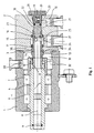
- the rotary feedthrough shown in Figure 1 includes a housing having a front housing part 1 and a connecting part designed as a rear housing part 2, which are sealed by a sealing ring 3 connected to each other.
- a hollow shaft 4 with a central passage 5 via a front and rear pivot bearing 6 and 7 is rotatably mounted about a central axis 8.
- a hollow clamping rod of a machine tool working spindle can be inserted sealed into the through-channel 5 via a sealing ring 9.
- At the rear end of the hollow shaft 4 with this rotatably connected and co-rotating first sealing sleeve 10 is arranged.
- the sealing sleeve 10 has a rear end-side sealing surface 13, on which a front end-side sealing surface 14 of a non-rotating sealing bushing 15 comes to rest.
- the sealing sleeve 10 and the sealing bush 15 are made of a wear-resistant and temperature-resistant material, expediently ceramic or the like.
- the sealing sleeve 10 coaxial sealing bushing 15 is axially displaceable in the rear housing part 2 and guided sealed by seals 16 and 17.
- a pressure piston 18 is arranged, which is supported via a compression spring 19 on an end cap 20 fixed in the housing part 2.
- the pressure piston 18 is sealed in a corresponding bore 21 of the rear housing part 2 via a seal 22 and has a sealingly projecting into the rear end of the sealing bush 15 front end pin 23.
- a plurality of radial openings 24 are provided, which open into a first annular space 25 within the housing part 2.
- the radial openings 24 are arranged such that they lie in front of the front end face 26 of the end pin 23 of the pressure piston 18.
- To the annular space 25 leads in the housing part 2 radially extending first supply channel 27th
- a second annular space 29 is provided, to which a second radial supply channel 30 leads. This is arranged radially extending in the housing part 2 next to the first supply channel 27.
- a collecting space 31 and an annular space 32 connected thereto with a radial discharge line 33 are provided inside the housing part 1. Via the discharge line 33, the leaked at the interface between the rotating sealing bush 10 and the rotationally fixed sealing bushing 15 and collected in the collecting space 31 leakage fluid can be removed.
- a compression spring 35 is clamped, through which the sealing bushing 15 is acted upon in the direction of the hollow shaft 14, that the sealing bush 15 is pressed with its sealing surface 14 constantly against the sealing surface 13 of the sealing sleeve 10.
- the two supply channels 27 and 30 are connected to a supply device shown schematically there.
- This comprises a compressed air supply line 36 which leads from a compressed air source 37 via a first switching valve 38 and a first check valve 39 to a line 40 connected to the first supply channel 27.
- the supply device also contains a cooling lubricant supply line 41, which opens from a coolant lubricant source 42 via a second switching valve 43 to the second supply channel 30 and also via a branch 44 with a second check valve 45 in the line 40 downstream of the first check valve 39.
- the two check valves 39 and 45 shown in FIG. 2 outside the housing can also be integrated in the rear housing part 2.
- a radial opening 46 is also provided, which leads to a space arranged between the seals 16 and 22. As a result, a leakage fluid collecting between the seals 16 and 22 for discharge can be discharged via a line 47 into a collecting container 48.
- the first switching valve 38 is closed and the second switching valve 43 is actuated, so that the cooling lubricant is supplied to the two supply channels 27 and 30.
- the cooling lubricant is supplied to the supply channel 30.
- the contact pressure between the sealing surfaces 13 and 14 is increased, whereby leakage of the supplied via the line 40 lubricant at the interface between the sliding sleeve 10 and the sliding bushing 15 is reduced.
- the supply channel 30 is vented, so that the contact pressure is lowered and thus excessive wear on the sealing surfaces 13 and 14 is prevented.
Landscapes
- Engineering & Computer Science (AREA)
- General Engineering & Computer Science (AREA)
- Mechanical Engineering (AREA)
- Sealing Devices (AREA)
- Joints Allowing Movement (AREA)
- Auxiliary Devices For Machine Tools (AREA)
- Braking Arrangements (AREA)
- Soil Working Implements (AREA)
Description
- Die Erfindung betrifft eine Drehdurchführung nach dem Oberbegriff des Anspruchs 1.
- Derartige Drehdurchführungen werden für die Zuführung eines Fluids zu einem rotierenden Maschinenteil eingesetzt. Besonders bei Werkzeugmaschinen wird über eine solche Drehdurchführung ein Kühlschmiermittel in eine hohle Arbeitsspindel der Werkzeugmaschine zur Kühlung oder Reinigung der Werkzeuge und/oder der Bearbeitungsstelle eingespeist. Bei den üblichen Drehdurchführungen wird die Schnittstelle zwischen dem rotierenden und dem stehenden Teil durch Dichtungsbuchsen oder Dichtungsringe mit aufeinander gleitenden Dichtflächen gebildet. Bei der Zuführung eines schmierfähigen Mediums, wie z.B. Kühlschmiermittel, wird der Dichtungsspalt zwischen den beiden Gleitflächen geschmiert, wodurch eine zu hohe Temperaturbelastung und ein zu starker Verschleiß verhindert wird. Es gibt allerdings auch Anwendungsfälle, bei denen ein nicht schmierfähiges Medium zugeführt werden muß. So ist bei bestimmten Anwendungen z.B. eine Druckluftzufuhr für die Kühlung des Werkzeugs und/oder Werkstücks oder auch für die Entfernung der Späne erforderlich. Dabei ergibt sich allerdings die Problematik, daß die dann fehlende Schmierung an den Gleitflächen zu einer verstärkten Wärmeentwicklung und erhöhtem Verschleiß führt.
- Aus der DE 199 32 355 A1 ist eine gattungsgemäße Drehdurchführung für wechselnde Medien bekannt. Dort stehen die Dichtflächen jedoch nur in Kontakt, wenn ein schmierfähiges Medium zugeführt wird. Bei der Zuführung eines nicht schmierfähigen Mediums werden die Dichtflächen auseinander bewegt, um einen zu starken Verschleiß der Dichtflächen zu verhindern. Um die dadurch entstehenden Leckverluste zu minimieren wird eine zusätzliche zylindrische Dichtung in Form eines Dichtspaltes zwischen der Außenwand einer drehfesten Hülse und der Innenwand einer Hohlwelle vorgesehen.
- Bei einer anderen Art von Drehdurchführungen wird das Problem der Schmierung und Kühlung der Gleitflächen dadurch gelöst, daß den aufeinander gleitenden Dichtelementen von außen her ein zusätzliches Kühl- oder Schmiermittel zugeführt wird. Dies erfordert jedoch einen nicht unerheblichen konstruktiven Aufwand, da das zusätzliche Kühl- und Schmiermittel zur kontinuierlichen Abführung der Reibungswärme ständig zu- und abgeführt werden muß.
- Aufgabe der Erfindung ist es, eine Drehdurchführung der eingangs genannten Art zu schaffen, die einfacher aufgebaut ist und neben einem geringen Verschleiß auch geringere Leckverluste sowohl bei der Zuführung von Kühlschmierstoffen als auch bei der Zuführung von Druckluft aufweist.
- Diese Aufgabe wird durch eine Drehdurchführung mit den Merkmalen des Anspruchs 1 gelöst. Zweckmäßige Ausgestaltungen und vorteilhafte Weiterbildungen der Erfindung sind in den Unteransprüchen angegeben.
- Bei der erfindungsgemäßen Drehdurchführung stehen die Gleitflächen auch in Kontakt, wenn die Zuführung des Kühlschmierstoffs oder der Druckluft abgeschaltet wird. Dadurch kann verhindert werden, daß beim Abschalten der Kühlschmierstoffzuführung ein Spalt zwischen den Gleitflächen entsteht, über den dann noch in der Zufuhrleitung befindlicher Kühlschmierstoff entweichen kann. Die nicht rotierende Gleitbuchse wird in Richtung der Hohlwelle so beaufschlagt, daß deren Gleitfläche ständig an die Gleitfläche der Hohlwelle angedrückt wird. Durch die radiale Einleitung an der Gleitbuchse ergibt sich bei der Zuführung von Druckluft auch keine zusätzliche axiale Belastung, die zu einem stärkeren Andruck der Gleitbuchse an die Gleitfläche der Hohlwelle führt. Nur bei der Zuführung von Kühlschmiermittel wird der Anpreßdruck erhöht, um eine optimale Abdichtung zu erreichen.
- Weitere Besonderheiten und Vorzüge der Erfindung ergeben sich aus der folgenden Beschreibung eines bevorzugten Ausführungsbeispiels anhand der Zeichnung. Es zeigen:
- Figur 1
- eine Drehdurchführung im Längsschnitt und
- Figur 2
- die Drehdurchführung mit den Anschlüssen für ein Kühlschmiermittel und für Luft.
- Die in Figur 1 dargestellte Drehdurchführung enthält ein Gehäuse mit einem vorderen Gehäuseteil 1 und einem als Anschlußteil ausgeführten hinteren Gehäuseteil 2, die durch einen Dichtring 3 abgedichtet miteinander verbunden sind. In dem vorderen Gehäuseteil 1 ist eine Hohlwelle 4 mit einem zentralen Durchgangskanal 5 über ein vorderes und hinteres Drehlager 6 bzw. 7 um eine Mittelachse 8 drehbar gelagert ist. An dem vorderen Ende der Hohlwelle 4 ist in den Durchgangskanal 5 z.B. eine hohle Spannstange einer Werkzeugmaschinen-Arbeitsspindel über einen Dichtring 9 abgedichtet einsteckbar. An dem hinteren Ende der Hohlwelle 4 ist eine mit dieser drehfest verbundene und mitrotierende erste Dichtungshülse 10 angeordnet. Diese ist in einen erweiterten Teil 11 des Durchgangskanals 5 am hinteren Ende der Hohlwelle 4 eingesteckt und über eine Radialdichtung 12 abgedichtet. Die Dichtungshülse 10 weist eine hintere stirnseitige Dichtfläche 13 auf, an der eine vordere stirnseitige Dichtfläche 14 einer nicht rotierenden Dichtungsbuchse 15 zur Anlage gelangt. Die Dichtungshülse 10 und die Dichtungsbuchse 15 bestehen aus einem verschleißfesten und temperaturbeständigen Material, zweckmäßigerweise Keramik oder dgl.
- Die zur Dichtungshülse 10 koaxiale Dichtungsbuchse 15 ist in dem hinteren Gehäuseteil 2 axial verschiebbar und durch Dichtungen 16 und 17 abgedichtet geführt. An dem hinteren Ende der Dichtungsbuchse 15 ist ein Druckkolben 18 angeordnet, der über eine Druckfeder 19 an einer im Gehäuseteil 2 befestigten Endkappe 20 abgestützt ist. Der Druckkolben 18 ist in einer entsprechenden Bohrung 21 des hinteren Gehäuseteils 2 über eine Dichtung 22 abgedichtet und weist einen in das hintere Ende der Dichtungsbuchse 15 abgedichtet hineinragenden vorderen Endzapfen 23 auf. In der Dichtungsbuchse 15 sind mehrere radiale Öffnungen 24 vorgesehen, die in einen ersten Ringraum 25 innerhalb des Gehäuseteils 2 münden. Die radialen Öffnungen 24 sind derart angeordnet, daß diese vor der vorderen Stirnfläche 26 des Endzapfens 23 des Druckkolbens 18 liegen. Zu dem Ringraum 25 führt ein im Gehäuseteil 2 radial verlaufender erster Zufuhrkanal 27.
- Zwischen der hinteren Stirnfläche 28 des Druckkolbens 18 und der Endkappe 20 ist ein zweiter Ringraum 29 vorgesehen, zu dem ein zweiter radialer Zufuhrkanal 30 führt. Dieser ist neben dem ersten Zufuhrkanal 27 radial verlaufend im Gehäuseteil 2 angeordnet.
- Im Bereich der Schnittstelle zwischen der Dichtfläche 13 der rotierenden Dichtungshülse 10 und der Dichtfläche 14 der drehfesten Dichtungsbuchse 15 ist innerhalb des Gehäuseteils 1 ein Auffangraum 31 und ein mit diesem verbundener Ringraum 32 mit einer radialen Abführleitung 33 vorgesehen. Über die Abführleitung 33 kann das an der Schnittstelle zwischen der rotierenden Dichtungsbuchse 10 und der drehfesten Dichtungsbuchse 15 austretende und im Auffangraum 31 gesammelte Leckagefluid abgeführt werden. Zwischen einem Ringbund 34 der Dichtungsbuchse 15 und dem Gehäuseteil 2 ist eine Druckfeder 35 eingespannt, durch welche die Dichtungsbuchse 15 so in Richtung der Hohlwelle 14 beaufschlagt wird, daß die Dichtungsbuchse 15 mit ihrer Dichtfläche 14 ständig an die Dichtfläche 13 der Dichtungshülse 10 angedrückt wird.
- Wie aus Figur 2 hervorgeht, sind die beiden Zufuhrkanäle 27 und 30 an eine dort schematisch dargestellte Versorgungseinrichtung angeschlossen. Diese umfaßt eine Druckluft-Versorgungsleitung 36, die von einer Druckluftquelle 37 über ein erstes Schaltventil 38 und ein erstes Rückschlagventil 39 zu einer an den ersten Zufuhrkanal 27 angeschlossenen Leitung 40 führt. Die Versorgungseinrichtung enthält außerdem eine Kühlschmierstoff-Versorgungsleitung 41, die von einer Kühlschmierstoffquelle 42 über ein zweites Schaltventil 43 zu dem zweiten Zufuhrkanal 30 und außerdem über eine Abzweigung 44 mit einem zweiten Rückschlagventil 45 in die Leitung 40 stromabwärts des ersten Rückschlagventils 39 mündet. Die beiden in Figur 2 außerhalb des Gehäuses dargestellten Rückschlagventile 39 und 45 können auch in dem hinteren Gehäuseteil 2 integriert sein. In dem hinteren Gehäuseteil 2 ist außerdem eine radiale Öffnung 46 vorgesehen, die zu einem zwischen den Dichtungen 16 und 22 angeordneten Zwischenraum führt. Dadurch kann ein sich zwischen den Dichtungen 16 und 22 sammelndes Leckagefluid zur Entlastung über eine Leitung 47 in einen Sammelbehälter 48 abgeführt werden.
- Bei der in Figur 2 gezeigten Schaltstellung ist das erste Schaltventil 38 geschlossen und das zweite Schaltventil 43 betätigt, so daß der Kühlschmierstoff den beiden Zufuhrkanälen 27 und 30 zugeführt wird. Durch die Zuführung des Kühlschmierstoffs zum Zufuhrkanal 30 wird der Anpreßdruck zwischen den Dichtflächen 13 und 14 erhöht, wodurch eine Leckage des über die Leitung 40 zugeführten Schmierstoffs an der Schnittstelle zwischen der Gleithülse 10 und der Gleitbuchse 15 verringert wird. Bei der Zuführung von Druckluft wird dagegen der Zufuhrkanal 30 entlüftet, so daß der Anpreßdruck gesenkt und somit ein zu starker Verschleiß an den Dichtflächen 13 und 14 verhindert wird.
Claims (12)
- Drehdurchführung für die wahlweise Zuführung von Kühlschmiermittel oder Luft zu einem rotierenden Maschinenteil, die eine in einem ersten Gehäuseteil (1) drehbar gelagerte Hohlwelle (4) mit einer ersten Dichtfläche (13) und eine innerhalb eines zweiten Gehäuseteils (2) verdrehfest angeordnete, zu der Hohlwelle (4) koaxiale Dichtungsbuchse (15) mit einer zweiten Dichtfläche (14) zur Anlage an der ersten Dichtfläche (13) enthält, dadurch gekennzeichnet, daß das zweite Gehäuseteil (2) einen an eine Kühlmittelversorgungsleitung (41) oder eine Druckluftversorgungsleitung (36) anschließbaren ersten seitlichen Zufuhrkanal (27) für die Zuführung des Kühlschmiermittels oder der Druckluft über mindestens eine radiale Öffnung (24) der Dichtungsbuchse (15) und einen bei der Zuführung des Kühlschmiermittels beaufschlagten zweiten Zufuhrkanal (30) für die Zuführung des Kühlschmiermittels an einen das hintere Ende der Dichtungsbuchse (15) verschließenden Druckkolben (18) zur Erhöhung des Anpreßdrucks der Dichtflächen (13, 14) enthält.
- Drehdurchführung nach Anspruch 1, dadurch gekennzeichnet, daß die Dichtungsbuchse (15) durch eine am zweiten Gehäuseteil (2) abgestützte Druckfeder (35) in Richtung der Hohlwelle (4) derart beaufschlagt wird, daß die Dichtfläche (14) der Dichtungsbuchse (15) ständig an die Dichtfläche (13) der Hohlwelle (4) angedrückt wird.
- Drehdurchführung nach Anspruch 1 oder 2, dadurch gekennzeichnet, daß die erste Dichtfläche (13) an einer am hinteren Ende der Hohlwelle (4) eingesetzten Dichtungshülse (10) vorgesehen ist.
- Drehdurchführung nach einem der Ansprüche 1 bis 3, dadurch gekennzeichnet, daß der Druckkolben (18) in das hintere Ende der Dichtungsbuchse (15) eingesetzt ist.
- Drehdurchführung nach einem der Ansprüche 1 bis 4, dadurch gekennzeichnet, daß der Druckkolben (18) einen in das hintere Ende der Dichtungsbuchse (15) abgedichtet hineinragenden vorderen Endzapfen (23) aufweist.
- Drehdurchführung nach einem der Ansprüche 1 bis 5, dadurch gekennzeichnet, daß der Druckkolben (18) über eine Druckfeder (19) an einer im zweiten Gehäuseteil (2) befestigten hinteren Endkappe (20) abgestützt ist.
- Drehdurchführung nach einem der Ansprüche 1 bis 6, dadurch gekennzeichnet, daß im Bereich der Schnittstelle zwischen den Dichtflächen (13, 14) der Hohlwelle (4) und der Dichtungsbuchse (15) innerhalb des ersten Gehäuseteils (1) ein Auffangraum (31) und ein mit diesem verbundener Ringraum (32) mit einer Abführleitung (33) vorgesehen ist.
- Drehdurchführung nach einem der Ansprüche 1 bis 7 dadurch gekennzeichnet, daß die beiden Zufuhrkanäle (27, 30) an eine Versorgungseinrichtung (36, 37, 41, 42) für die Druckluft- und Kühlschmiennittelversorgung angeschlossen sind.
- Drehdurchführung nach Anspruch 8, dadurch gekennzeichnet, daß die Versorgungseinrichtung (36, 37, 41, 42) eine Druckluft-Versorgungsleitung (36) enthält, die von einer Druckluftquelle (37) über ein erstes Schaltventil (38) und ein erstes Rückschlagventil (39) zu einer an den ersten Zufuhrkanal (27) angeschlossenen Leitung (40) führt.
- Drehdurchführung nach Anspruch 9, dadurch gekennzeichnet, daß die Versorgungseinrichtung (36, 37, 41, 42) eine Kühlschmierstoff-Versorgungsleitung (41) enthält, die von einer Kühlschmierstoffquelle (42) über ein zweites Schaltventil (43) zu dem zweiten Zufuhrkanal (30) und über eine Abzweigung (44) mit einem zweiten Rückschlagventil (45) in die Leitung (40) stromabwärts des ersten Rückschlagventils (39) mündet.
- Drehdurchführung nach Anspruch 9, dadurch gekennzeichnet, daß das erste Rückschlagventil (39) in dem zweiten Gehäuseteil (2) integriert ist.
- Drehdurchführung nach Anspruch 10 oder 11, dadurch gekennzeichnet, daß das zweite Rückschlagventil (45) in dem zweiten Gehäuseteil (2) integriert ist.
Applications Claiming Priority (3)
| Application Number | Priority Date | Filing Date | Title |
|---|---|---|---|
| DE10225272 | 2002-06-07 | ||
| DE2002125272 DE10225272B4 (de) | 2002-06-07 | 2002-06-07 | Drehdurchführung |
| PCT/EP2003/005881 WO2003104707A1 (de) | 2002-06-07 | 2003-06-04 | Drehdurchführung |
Publications (2)
| Publication Number | Publication Date |
|---|---|
| EP1514047A1 EP1514047A1 (de) | 2005-03-16 |
| EP1514047B1 true EP1514047B1 (de) | 2006-10-25 |
Family
ID=29594308
Family Applications (1)
| Application Number | Title | Priority Date | Filing Date |
|---|---|---|---|
| EP03757020A Expired - Lifetime EP1514047B1 (de) | 2002-06-07 | 2003-06-04 | Drehdurchführung |
Country Status (7)
| Country | Link |
|---|---|
| US (1) | US6929099B2 (de) |
| EP (1) | EP1514047B1 (de) |
| JP (1) | JP4028868B2 (de) |
| AT (1) | ATE343754T1 (de) |
| DE (2) | DE10225272B4 (de) |
| ES (1) | ES2273030T3 (de) |
| WO (1) | WO2003104707A1 (de) |
Families Citing this family (16)
| Publication number | Priority date | Publication date | Assignee | Title |
|---|---|---|---|---|
| DE102004023102A1 (de) * | 2004-05-11 | 2005-12-08 | Deere & Company, Moline | Druckmittelbetriebene Anordnung |
| DE102005038459A1 (de) | 2005-08-13 | 2007-02-22 | Ott-Jakob Gmbh & Co. Spanntechnik Kg | Drehdurchführung mit Leckagesensor |
| US7692553B2 (en) * | 2006-07-21 | 2010-04-06 | Deublin Company | Leak detecting system for rotating union |
| US9375762B2 (en) * | 2006-08-25 | 2016-06-28 | Steven A. Loussaert | Grease port cleaning tool |
| DE102007051562A1 (de) * | 2007-10-29 | 2009-04-30 | Robert Bosch Gmbh | Kupplungseinrichtung zur Übertragung eines Mediums von einem ortsfesten Teil auf ein drehbares Teil |
| DE102008021049B3 (de) * | 2008-04-26 | 2009-12-10 | Ex-Cell-O Gmbh | Verfahren zum Kühlen und Schmieren eines Werkzeugs und zum Reinigen der bearbeiteten Fläche |
| DE102008036051B3 (de) * | 2008-08-01 | 2009-11-19 | Ott-Jakob Spanntechnik Gmbh | Drehdurchführung |
| US8453675B2 (en) * | 2009-12-01 | 2013-06-04 | Deublin Company | Rotary union with selectively controlled seal |
| CN101865343A (zh) * | 2010-06-07 | 2010-10-20 | 苏州有色金属研究院有限公司 | 气动压紧式端面密封的新型回转接头 |
| DE102010035761B4 (de) | 2010-08-28 | 2012-05-03 | Ott-Jakob Spanntechnik Gmbh | Drehdurchführung |
| JP5767021B2 (ja) | 2011-05-26 | 2015-08-19 | 株式会社ナカニシ | 歯科用ハンドピースの流体回路接続構造 |
| US10571058B2 (en) | 2016-02-01 | 2020-02-25 | Deublin Company | Rotary union with integral sensor array |
| DE102017008654A1 (de) * | 2017-09-14 | 2019-03-14 | Franz Kessler Gmbh | Motorspindel für eine Werkzeugmaschine mit integrierter Kühlung und Drehdurchführungsmodul |
| JP7124548B2 (ja) * | 2018-08-10 | 2022-08-24 | 住友ゴム工業株式会社 | 離型剤塗布ユニット、及び離型剤塗布装置 |
| US20240240738A1 (en) * | 2021-05-05 | 2024-07-18 | Deublin Gmbh | Multimedia-compatible rotary union |
| US20240344643A1 (en) | 2023-04-11 | 2024-10-17 | Murzanski Engineering | Rotary Union |
Family Cites Families (15)
| Publication number | Priority date | Publication date | Assignee | Title |
|---|---|---|---|---|
| FR2575526B1 (fr) * | 1984-12-28 | 1987-02-13 | Telemecanique Electrique | Ensemble de raccords fonctionnels pour verin pneumatique a montage combine pour assurer deux fonctions au moins |
| DE3810060A1 (de) * | 1988-03-25 | 1989-10-12 | Ott Gmbh A | Drehdurchfuehrung fuer fluide |
| DE3817799C1 (en) * | 1988-05-26 | 1989-11-30 | A. Ott Gmbh, 8960 Kempten, De | Rotary transmission leadthrough for fluids, in particular for machine-tool spindles |
| US4976282A (en) * | 1989-04-12 | 1990-12-11 | Deublin Company | Coolant union with fluid actuated seal assembly |
| DE4210009C2 (de) * | 1992-03-27 | 1994-05-11 | Heidelberger Druckmasch Ag | Drehdurchführung |
| JP2799657B2 (ja) * | 1993-02-19 | 1998-09-21 | 株式会社牧野フライス製作所 | ロータリジョイント |
| DE4325097C3 (de) * | 1993-07-27 | 2001-07-05 | Hammelmann Paul Maschf | Hochdruckpumpe zur Versorgung von mehreren Abnehmern mit Preßwasser |
| US5538292A (en) * | 1995-01-17 | 1996-07-23 | Midwest Brake Bond Company | Rotary union |
| JP3675535B2 (ja) * | 1995-10-06 | 2005-07-27 | 株式会社牧野フライス製作所 | ロータリジョイント及び回転体への流体供給装置 |
| DE19543612C1 (de) * | 1995-11-23 | 1997-05-07 | Glyco Antriebstechnik Gmbh | Spannvorrichtung mit integrierter Fluid-Drehdurchführung |
| DE19820362A1 (de) * | 1998-05-07 | 1999-11-18 | Gat Gmbh | Vorrichtung zum Überführen eines Fluids |
| EP1046852A3 (de) * | 1999-04-22 | 2002-11-27 | Talco, Inc. | Trockenlaufende Kühlmittel-Verbindung |
| DE19932355B4 (de) * | 1999-07-10 | 2010-07-15 | GAT Gesellschaft für Antriebstechnik mbH | Drehdurchführung für wechselnde Medien |
| JP3549194B2 (ja) * | 2000-02-22 | 2004-08-04 | 日本スピードショア株式会社 | 工作加工方法およびそれに用いる霧状体供給装置 |
| US6386221B1 (en) * | 2001-04-05 | 2002-05-14 | Snap-Tite Technologies, Inc. | Journal mounted solenoid valve |
-
2002
- 2002-06-07 DE DE2002125272 patent/DE10225272B4/de not_active Expired - Fee Related
-
2003
- 2003-06-04 WO PCT/EP2003/005881 patent/WO2003104707A1/de not_active Ceased
- 2003-06-04 DE DE50305503T patent/DE50305503D1/de not_active Expired - Lifetime
- 2003-06-04 EP EP03757020A patent/EP1514047B1/de not_active Expired - Lifetime
- 2003-06-04 ES ES03757020T patent/ES2273030T3/es not_active Expired - Lifetime
- 2003-06-04 JP JP2004511737A patent/JP4028868B2/ja not_active Expired - Fee Related
- 2003-06-04 AT AT03757020T patent/ATE343754T1/de not_active IP Right Cessation
-
2004
- 2004-01-21 US US10/763,065 patent/US6929099B2/en not_active Expired - Fee Related
Also Published As
| Publication number | Publication date |
|---|---|
| DE10225272A1 (de) | 2003-12-24 |
| ES2273030T3 (es) | 2007-05-01 |
| JP4028868B2 (ja) | 2007-12-26 |
| JP2005520107A (ja) | 2005-07-07 |
| WO2003104707A1 (de) | 2003-12-18 |
| DE10225272B4 (de) | 2005-05-04 |
| US6929099B2 (en) | 2005-08-16 |
| US20040200670A1 (en) | 2004-10-14 |
| DE50305503D1 (de) | 2006-12-07 |
| EP1514047A1 (de) | 2005-03-16 |
| ATE343754T1 (de) | 2006-11-15 |
Similar Documents
| Publication | Publication Date | Title |
|---|---|---|
| EP1514047B1 (de) | Drehdurchführung | |
| EP0840866B1 (de) | Drehdurchführung für hohe drücke und hohe relativgeschwindigkeiten | |
| EP1069362B1 (de) | Drehdurchführung für wechselnde Medien | |
| EP0780192B2 (de) | Spindeleinheit für Werkzeugmaschinen | |
| DE69002268T2 (de) | Kuehleinheit mit fluidbetaetigter dichtung. | |
| EP0498146A2 (de) | Drehdurchführung für zwei unterschiedliche Fluide | |
| EP2058085B1 (de) | Wellenkühlung für eine Werkzeug-Motorspindel | |
| EP1254739B1 (de) | Spindelkopf für Werkzeuge | |
| EP0955123B1 (de) | Vorrichtung zum Überführen eines Fluids | |
| EP0368024A2 (de) | Drehdurchführung für zwei unterschiedliche Fluide | |
| DE102021111688A1 (de) | Multimedientaugliche Drehdurchführung | |
| EP0857258B1 (de) | Vorrichtung zum ankuppeln der kühlmedienführung eines rotationsteiles | |
| EP4334619B1 (de) | Multimedientaugliche drehdurchführung | |
| DE3817799C1 (en) | Rotary transmission leadthrough for fluids, in particular for machine-tool spindles | |
| EP0105860B1 (de) | Drehdurchführung, insbesondere für drehende Werkzeuge | |
| DE4019987C2 (de) | Drehdurchführung | |
| DE102008036051B3 (de) | Drehdurchführung | |
| DE102016115039A1 (de) | Werkzeugaufnahme | |
| EP3275589B1 (de) | Arbeitsspindel-kühleinrichtung und werkzeugmaschinen-bearbeitungseinheit mit einer derartigen arbeitspindel-kühleinrichtung | |
| DE19960907C1 (de) | Drehverteiler zur Übertragung eines Fluids | |
| EP0974782B1 (de) | Druckmittelzuführungseinrichtung | |
| DE102004023231B4 (de) | Einrichtung mit einer Drehdurchführung für eine Flüssigkeit | |
| DE3804962C1 (en) | Hydro-mechanical tool-clamping system for hollow work spindles carried in rolling bearings, with integrated oil lubrication through the spindle | |
| DE9101277U1 (de) | Drehdurchführung für zwei unterschiedliche Fluide | |
| DE1263419B (de) | Vorrichtung an Werkzeugmaschinen zur Aufrechterhaltung des statischen UEberdruckes |
Legal Events
| Date | Code | Title | Description |
|---|---|---|---|
| PUAI | Public reference made under article 153(3) epc to a published international application that has entered the european phase |
Free format text: ORIGINAL CODE: 0009012 |
|
| 17P | Request for examination filed |
Effective date: 20050107 |
|
| AK | Designated contracting states |
Kind code of ref document: A1 Designated state(s): AT BE BG CH CY CZ DE DK EE ES FI FR GB GR HU IE IT LI LU MC NL PT RO SE SI SK TR |
|
| AX | Request for extension of the european patent |
Extension state: AL LT LV MK |
|
| DAX | Request for extension of the european patent (deleted) | ||
| GRAP | Despatch of communication of intention to grant a patent |
Free format text: ORIGINAL CODE: EPIDOSNIGR1 |
|
| GRAS | Grant fee paid |
Free format text: ORIGINAL CODE: EPIDOSNIGR3 |
|
| GRAA | (expected) grant |
Free format text: ORIGINAL CODE: 0009210 |
|
| AK | Designated contracting states |
Kind code of ref document: B1 Designated state(s): AT BE BG CH CY CZ DE DK EE ES FI FR GB GR HU IE IT LI LU MC NL PT RO SE SI SK TR |
|
| PG25 | Lapsed in a contracting state [announced via postgrant information from national office to epo] |
Ref country code: SI Free format text: LAPSE BECAUSE OF FAILURE TO SUBMIT A TRANSLATION OF THE DESCRIPTION OR TO PAY THE FEE WITHIN THE PRESCRIBED TIME-LIMIT Effective date: 20061025 Ref country code: IE Free format text: LAPSE BECAUSE OF FAILURE TO SUBMIT A TRANSLATION OF THE DESCRIPTION OR TO PAY THE FEE WITHIN THE PRESCRIBED TIME-LIMIT Effective date: 20061025 Ref country code: RO Free format text: LAPSE BECAUSE OF FAILURE TO SUBMIT A TRANSLATION OF THE DESCRIPTION OR TO PAY THE FEE WITHIN THE PRESCRIBED TIME-LIMIT Effective date: 20061025 Ref country code: SK Free format text: LAPSE BECAUSE OF FAILURE TO SUBMIT A TRANSLATION OF THE DESCRIPTION OR TO PAY THE FEE WITHIN THE PRESCRIBED TIME-LIMIT Effective date: 20061025 Ref country code: FI Free format text: LAPSE BECAUSE OF FAILURE TO SUBMIT A TRANSLATION OF THE DESCRIPTION OR TO PAY THE FEE WITHIN THE PRESCRIBED TIME-LIMIT Effective date: 20061025 Ref country code: NL Free format text: LAPSE BECAUSE OF FAILURE TO SUBMIT A TRANSLATION OF THE DESCRIPTION OR TO PAY THE FEE WITHIN THE PRESCRIBED TIME-LIMIT Effective date: 20061025 Ref country code: CZ Free format text: LAPSE BECAUSE OF FAILURE TO SUBMIT A TRANSLATION OF THE DESCRIPTION OR TO PAY THE FEE WITHIN THE PRESCRIBED TIME-LIMIT Effective date: 20061025 |
|
| REG | Reference to a national code |
Ref country code: GB Ref legal event code: FG4D Free format text: NOT ENGLISH |
|
| REG | Reference to a national code |
Ref country code: CH Ref legal event code: NV Representative=s name: LUCHS & PARTNER PATENTANWAELTE Ref country code: CH Ref legal event code: EP |
|
| REG | Reference to a national code |
Ref country code: IE Ref legal event code: FG4D Free format text: LANGUAGE OF EP DOCUMENT: GERMAN |
|
| REF | Corresponds to: |
Ref document number: 50305503 Country of ref document: DE Date of ref document: 20061207 Kind code of ref document: P |
|
| PG25 | Lapsed in a contracting state [announced via postgrant information from national office to epo] |
Ref country code: DK Free format text: LAPSE BECAUSE OF FAILURE TO SUBMIT A TRANSLATION OF THE DESCRIPTION OR TO PAY THE FEE WITHIN THE PRESCRIBED TIME-LIMIT Effective date: 20070125 Ref country code: BG Free format text: LAPSE BECAUSE OF FAILURE TO SUBMIT A TRANSLATION OF THE DESCRIPTION OR TO PAY THE FEE WITHIN THE PRESCRIBED TIME-LIMIT Effective date: 20070125 Ref country code: SE Free format text: LAPSE BECAUSE OF FAILURE TO SUBMIT A TRANSLATION OF THE DESCRIPTION OR TO PAY THE FEE WITHIN THE PRESCRIBED TIME-LIMIT Effective date: 20070125 |
|
| PG25 | Lapsed in a contracting state [announced via postgrant information from national office to epo] |
Ref country code: PT Free format text: LAPSE BECAUSE OF FAILURE TO SUBMIT A TRANSLATION OF THE DESCRIPTION OR TO PAY THE FEE WITHIN THE PRESCRIBED TIME-LIMIT Effective date: 20070326 |
|
| NLV1 | Nl: lapsed or annulled due to failure to fulfill the requirements of art. 29p and 29m of the patents act | ||
| REG | Reference to a national code |
Ref country code: ES Ref legal event code: FG2A Ref document number: 2273030 Country of ref document: ES Kind code of ref document: T3 |
|
| GBV | Gb: ep patent (uk) treated as always having been void in accordance with gb section 77(7)/1977 [no translation filed] |
Effective date: 20061025 |
|
| EN | Fr: translation not filed | ||
| REG | Reference to a national code |
Ref country code: IE Ref legal event code: FD4D |
|
| PLBE | No opposition filed within time limit |
Free format text: ORIGINAL CODE: 0009261 |
|
| STAA | Information on the status of an ep patent application or granted ep patent |
Free format text: STATUS: NO OPPOSITION FILED WITHIN TIME LIMIT |
|
| 26N | No opposition filed |
Effective date: 20070726 |
|
| PG25 | Lapsed in a contracting state [announced via postgrant information from national office to epo] |
Ref country code: GB Free format text: LAPSE BECAUSE OF FAILURE TO SUBMIT A TRANSLATION OF THE DESCRIPTION OR TO PAY THE FEE WITHIN THE PRESCRIBED TIME-LIMIT Effective date: 20061025 |
|
| BERE | Be: lapsed |
Owner name: OTT-JAKOB G.M.B.H. & CO. SPANNTECHNIK KG Effective date: 20070630 |
|
| PG25 | Lapsed in a contracting state [announced via postgrant information from national office to epo] |
Ref country code: MC Free format text: LAPSE BECAUSE OF NON-PAYMENT OF DUE FEES Effective date: 20070630 |
|
| PG25 | Lapsed in a contracting state [announced via postgrant information from national office to epo] |
Ref country code: BE Free format text: LAPSE BECAUSE OF NON-PAYMENT OF DUE FEES Effective date: 20070630 |
|
| PG25 | Lapsed in a contracting state [announced via postgrant information from national office to epo] |
Ref country code: FR Free format text: LAPSE BECAUSE OF FAILURE TO SUBMIT A TRANSLATION OF THE DESCRIPTION OR TO PAY THE FEE WITHIN THE PRESCRIBED TIME-LIMIT Effective date: 20070608 Ref country code: GR Free format text: LAPSE BECAUSE OF FAILURE TO SUBMIT A TRANSLATION OF THE DESCRIPTION OR TO PAY THE FEE WITHIN THE PRESCRIBED TIME-LIMIT Effective date: 20070126 |
|
| PG25 | Lapsed in a contracting state [announced via postgrant information from national office to epo] |
Ref country code: AT Free format text: LAPSE BECAUSE OF NON-PAYMENT OF DUE FEES Effective date: 20070604 |
|
| PG25 | Lapsed in a contracting state [announced via postgrant information from national office to epo] |
Ref country code: FR Free format text: LAPSE BECAUSE OF FAILURE TO SUBMIT A TRANSLATION OF THE DESCRIPTION OR TO PAY THE FEE WITHIN THE PRESCRIBED TIME-LIMIT Effective date: 20061025 |
|
| PG25 | Lapsed in a contracting state [announced via postgrant information from national office to epo] |
Ref country code: EE Free format text: LAPSE BECAUSE OF FAILURE TO SUBMIT A TRANSLATION OF THE DESCRIPTION OR TO PAY THE FEE WITHIN THE PRESCRIBED TIME-LIMIT Effective date: 20061025 |
|
| PG25 | Lapsed in a contracting state [announced via postgrant information from national office to epo] |
Ref country code: LU Free format text: LAPSE BECAUSE OF NON-PAYMENT OF DUE FEES Effective date: 20070604 Ref country code: CY Free format text: LAPSE BECAUSE OF FAILURE TO SUBMIT A TRANSLATION OF THE DESCRIPTION OR TO PAY THE FEE WITHIN THE PRESCRIBED TIME-LIMIT Effective date: 20061025 |
|
| PG25 | Lapsed in a contracting state [announced via postgrant information from national office to epo] |
Ref country code: HU Free format text: LAPSE BECAUSE OF FAILURE TO SUBMIT A TRANSLATION OF THE DESCRIPTION OR TO PAY THE FEE WITHIN THE PRESCRIBED TIME-LIMIT Effective date: 20070426 Ref country code: TR Free format text: LAPSE BECAUSE OF FAILURE TO SUBMIT A TRANSLATION OF THE DESCRIPTION OR TO PAY THE FEE WITHIN THE PRESCRIBED TIME-LIMIT Effective date: 20061025 |
|
| PGFP | Annual fee paid to national office [announced via postgrant information from national office to epo] |
Ref country code: IT Payment date: 20140627 Year of fee payment: 12 |
|
| PG25 | Lapsed in a contracting state [announced via postgrant information from national office to epo] |
Ref country code: IT Free format text: LAPSE BECAUSE OF NON-PAYMENT OF DUE FEES Effective date: 20150604 |
|
| PGFP | Annual fee paid to national office [announced via postgrant information from national office to epo] |
Ref country code: ES Payment date: 20160610 Year of fee payment: 14 Ref country code: DE Payment date: 20160610 Year of fee payment: 14 Ref country code: CH Payment date: 20160613 Year of fee payment: 14 |
|
| REG | Reference to a national code |
Ref country code: DE Ref legal event code: R119 Ref document number: 50305503 Country of ref document: DE |
|
| REG | Reference to a national code |
Ref country code: CH Ref legal event code: PL |
|
| PG25 | Lapsed in a contracting state [announced via postgrant information from national office to epo] |
Ref country code: LI Free format text: LAPSE BECAUSE OF NON-PAYMENT OF DUE FEES Effective date: 20170630 Ref country code: CH Free format text: LAPSE BECAUSE OF NON-PAYMENT OF DUE FEES Effective date: 20170630 Ref country code: DE Free format text: LAPSE BECAUSE OF NON-PAYMENT OF DUE FEES Effective date: 20180103 |
|
| REG | Reference to a national code |
Ref country code: ES Ref legal event code: FD2A Effective date: 20181113 |
|
| PG25 | Lapsed in a contracting state [announced via postgrant information from national office to epo] |
Ref country code: ES Free format text: LAPSE BECAUSE OF NON-PAYMENT OF DUE FEES Effective date: 20170605 |