EP2056428A2 - Befestigungsverfahren eines Statorkörpers im Gehäuse und Verdichter mit einem solchen Stator - Google Patents
Befestigungsverfahren eines Statorkörpers im Gehäuse und Verdichter mit einem solchen Stator Download PDFInfo
- Publication number
- EP2056428A2 EP2056428A2 EP08018807A EP08018807A EP2056428A2 EP 2056428 A2 EP2056428 A2 EP 2056428A2 EP 08018807 A EP08018807 A EP 08018807A EP 08018807 A EP08018807 A EP 08018807A EP 2056428 A2 EP2056428 A2 EP 2056428A2
- Authority
- EP
- European Patent Office
- Prior art keywords
- stator core
- die
- outside contour
- steel sheet
- sheets
- Prior art date
- Legal status (The legal status is an assumption and is not a legal conclusion. Google has not performed a legal analysis and makes no representation as to the accuracy of the status listed.)
- Withdrawn
Links
- 238000000034 method Methods 0.000 title claims abstract description 24
- 229910000831 Steel Inorganic materials 0.000 claims abstract description 40
- 239000010959 steel Substances 0.000 claims abstract description 40
- 238000010030 laminating Methods 0.000 claims abstract description 11
- 238000005096 rolling process Methods 0.000 claims description 27
- 230000006835 compression Effects 0.000 claims description 11
- 238000007906 compression Methods 0.000 claims description 11
- 239000003507 refrigerant Substances 0.000 description 7
- 238000004519 manufacturing process Methods 0.000 description 6
- 238000004804 winding Methods 0.000 description 4
- RYGMFSIKBFXOCR-UHFFFAOYSA-N Copper Chemical compound [Cu] RYGMFSIKBFXOCR-UHFFFAOYSA-N 0.000 description 2
- XEEYBQQBJWHFJM-UHFFFAOYSA-N Iron Chemical compound [Fe] XEEYBQQBJWHFJM-UHFFFAOYSA-N 0.000 description 2
- 230000003247 decreasing effect Effects 0.000 description 2
- XAGFODPZIPBFFR-UHFFFAOYSA-N aluminium Chemical compound [Al] XAGFODPZIPBFFR-UHFFFAOYSA-N 0.000 description 1
- 229910052782 aluminium Inorganic materials 0.000 description 1
- 238000000137 annealing Methods 0.000 description 1
- 229910052802 copper Inorganic materials 0.000 description 1
- 239000010949 copper Substances 0.000 description 1
- 230000000694 effects Effects 0.000 description 1
- 230000005674 electromagnetic induction Effects 0.000 description 1
- 229910052742 iron Inorganic materials 0.000 description 1
- 230000035945 sensitivity Effects 0.000 description 1
Images



Classifications
-
- H—ELECTRICITY
- H02—GENERATION; CONVERSION OR DISTRIBUTION OF ELECTRIC POWER
- H02K—DYNAMO-ELECTRIC MACHINES
- H02K15/00—Processes or apparatus specially adapted for manufacturing, assembling, maintaining or repairing of dynamo-electric machines
- H02K15/02—Processes or apparatus specially adapted for manufacturing, assembling, maintaining or repairing of dynamo-electric machines of stator or rotor bodies
- H02K15/028—Fastening stator or rotor bodies to casings, supports, shafts or hubs
-
- H—ELECTRICITY
- H02—GENERATION; CONVERSION OR DISTRIBUTION OF ELECTRIC POWER
- H02K—DYNAMO-ELECTRIC MACHINES
- H02K1/00—Details of the magnetic circuit
- H02K1/06—Details of the magnetic circuit characterised by the shape, form or construction
- H02K1/12—Stationary parts of the magnetic circuit
- H02K1/18—Means for mounting or fastening magnetic stationary parts on to, or to, the stator structures
- H02K1/187—Means for mounting or fastening magnetic stationary parts on to, or to, the stator structures to inner stators
-
- H—ELECTRICITY
- H02—GENERATION; CONVERSION OR DISTRIBUTION OF ELECTRIC POWER
- H02K—DYNAMO-ELECTRIC MACHINES
- H02K5/00—Casings; Enclosures; Supports
- H02K5/04—Casings or enclosures characterised by the shape, form or construction thereof
-
- Y—GENERAL TAGGING OF NEW TECHNOLOGICAL DEVELOPMENTS; GENERAL TAGGING OF CROSS-SECTIONAL TECHNOLOGIES SPANNING OVER SEVERAL SECTIONS OF THE IPC; TECHNICAL SUBJECTS COVERED BY FORMER USPC CROSS-REFERENCE ART COLLECTIONS [XRACs] AND DIGESTS
- Y10—TECHNICAL SUBJECTS COVERED BY FORMER USPC
- Y10T—TECHNICAL SUBJECTS COVERED BY FORMER US CLASSIFICATION
- Y10T29/00—Metal working
- Y10T29/49—Method of mechanical manufacture
- Y10T29/49002—Electrical device making
- Y10T29/49009—Dynamoelectric machine
Definitions
- the present invention relates to a method of fixing a stator core and an electric compressor with a motor using the method.
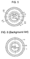
- a stator 100 of a motor is shown which is fixed inside a cylindrical housing 150.
- a stator core 110 of the stator 100 is formed of a plurality of stator core sheets 111 laminated together into a stack (refer to Fig. 7 ). It is noted that stator windings are not shown in Fig. 6 .
- a common electromagnetic steel sheet 160 is rolled to a predetermined thickness.
- Each of the stator core sheets 111 is blanked off from the steel sheet 160 by using a die.
- a predetermined number of the stator core sheets 111 are laminated to form the stator core 110.
- FIG. 8 there exists a variation in the thickness of the steel sheet 160 in the direction perpendicular to a rolling direction of the steel sheet 160.
- the blanked stator core sheets 111 are turned and laminated one on another so that the perpendicularity is accomplished.
- the stator core 110 has on the inner circumferential surface thereof a plurality of teeth 110A, around each of which a copper wire (not shown) is wound thereby to form the stator 100 of the motor.
- the copper wires are insulated from the teeth 110A.
- the stator 100 is fixed inside the housing 150 by any suitable method such as shrink fit. As shown in Fig. 6 , the stator 100 is fixed over the entire circumference by the housing 150.
- Japanese Patent Application Publication No. 10-24333 discloses a method of manufacturing a stator core sheet whose axial contour is circular or a true circle. Specifically, a blanking die is controlled such that a stator core sheet having a true circle is made by correcting an elliptical shape of the stator core sheet elongated in the direction perpendicular to the rolling direction of electromagnetic steel sheet and contracted in the rolling direction.
- Japanese Patent Application Publication No. 2006-299834 discloses an electric compressor having a housing whose inner circumferential surface is formed with a plurality of projections by which the stator of an electric motor for the compressor is fixed to the housing.
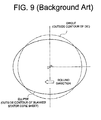
- a stator core sheet 111 blanked from the steel sheet 160 by using a die is strained, as shown in Fig. 9.
- Fig. 9 shows an outside contour of the die for blanking the stator core sheet 111 from the steel sheet 160 and an outside contour of the blanked stator core sheet 111. While the outside contour of the die is circular, the outside contour of the blanked stator core sheet 111 is elliptical. That is, the outside contour of the stator core sheet 111 cut by a circular blanking die is elliptical. More specifically, the stator core sheet 111 may be formed such that its outside diameter is increased in the rolling direction of the steel sheet 160 and decreased in the direction perpendicular to the rolling direction. Alternatively, the stator core sheet 111 may be formed such that its outside diameter is decreased in the rolling direction of the steel sheet 160 and increased in the direction perpendicular to the rolling direction.
- stator core sheets 111 blanked off from the electromagnetic steel sheet 160 varies from one production lot to another, it is necessary for a manufacturer of the stator core 110 to control the dimension of the outside diameter of the stator core sheets 111. Therefore, it is necessary for the manufacturer to make adjustment of dies for minimizing the number of stator core sheets falling outside the tolerance and for ensuring the process capability.
- the outer circumferential surface of the housing 150 may have a flat portion formed by planing, on which a sensor is mounted.
- a sensor fixing the stator 100 in the housing 150 with the outer circumferential surface of the stator core 110 strained, the flatness of the flat portion deteriorates. If the sensor is mounted on such a deteriorated flat portion, the sensor may not function properly due to poor sensitivity.
- the stator 100 is firstly fixed in the housing 150 and then any appropriate provision is made to prevent foreign matters from entering into the housing 150 before performing the planing for the flat mounting portion for the sensor.
- the strained stator core sheets each having 18 slots are turned for each 60 degrees in laminating such sheets one another thereby to form a laminated stator core. If such a stator core 110 is fixed in the housing 150 by shrink fit, the contact area between the inner circumferential surface of the housing 150 and the outer circumferential surface of the stator core 110 is smaller than that in the case where the axial contour of the stator core 110 is a true circle. As a result, there is fear that the stator 100 is rotated because the fixation of the stator 100 to the housing 150 fails to resist the torque of the motor operating under a high load.
- the present invention is directed to a method of fixing a stator core in a housing without being influenced by the strain of stator core sheets and with little deformation to the housing after assembling.
- the present invention is directed to an electric compressor with a motor using the method.
- the present invention provides a method of fixing a stator core in a cylindrical housing.
- the method includes the following steps.
- the first step is a step of blanking a plurality of stator core sheets from an electromagnetic steel sheet by using a die.
- the die has a circular outside contour for blanking the stator core sheets from the electromagnetic steel sheet and each of the blanked stator core sheets has an outside contour.
- the second step is a step of forming the stator core by laminating the blanked stator core sheets one on another.
- the third step is a step of setting a non-fixing position of the stator core to the housing in such an angular position where difference in diametral dimension of the outside contour between the die and the stator core is relatively large.
- the present invention also provides an electric compressor having therein a compression mechanism.
- the electric compressor includes a cylindrical motor housing and an annular stator core.
- the stator core is fixed in the motor housing with at least a part of an outer circumferential surface of the stator core in contact with inner projections of the motor housing.
- the stator core is formed of a plurality of stator core sheets laminated one on another. Each of the stator core sheets is blanked off from an electromagnetic steel sheet by using a die.
- the die has a circular outside contour for blanking the stator core sheets from the electromagnetic steel sheet and each of the blanked stator core sheets has an outside contour.
- a non-fixing position of the stator core to the motor housing is set between the inner projections in such an angular position where difference in diametral dimension of the outside contour between the die and the stator core is relatively large.
- the electric compressor 10 includes a closed housing assembly 11.
- This housing assembly 11 includes a cylindrical main housing 12 with its rear end closed and a front housing 13 which is fixedly joined to the front end of the main housing 12.
- This main housing 12 is made, for example, of forged aluminum.
- the main housing 12 includes a compressor housing portion 14, a motor housing portion 15 formed integrally with the compressor housing portion 14, and a rear housing portion 16 formed integrally with the motor housing portion 15.
- the motor housing portion 15 will be referred to as a motor housing 15 hereinafter.
- the compressor housing portion 14 has therein a scroll-type compression mechanism 17.
- This compression mechanism 17 includes a base plate 18, a fixed scroll member 19 located in the front of the base plate 18, and a movable scroll member 20 provided between the base plate 18 and the fixed scroll member 19.
- the base plate 18 and the fixed scroll member 19 are fixedly fitted in the compressor housing portion 14 at a stepped part of the inner circumferential surface 14A thereof.
- the fixed scroll member 19 and the movable scroll member 20 cooperate to form therebetween compression chambers 21.
- the compressor housing portion 14 has therein a suction chamber 22 located behind the base plate 18. Refrigerant gas in the suction chamber 22 is drawn into the compression chamber 21 through a suction port 18A formed in the base plate 18 for compression in the compression chambers 21.
- the gas compressed in the compression chambers 21 is discharged to a discharge chamber 23 formed in the front housing 13 through a discharge port 19A formed in the fixed scroll member 19.
- the front housing 13 has an outlet port 13A for delivering the compressed refrigerant gas into the external refrigerant circuit of the compressor 10.
- the rear housing portion 16 has an inlet port 16A for introducing the refrigerant gas from the external refrigerant circuit into the suction chamber 22.
- the motor housing 15 of a cylindrical shape has therein an electric motor M including a stator 31 and a rotor 35.
- the stator 31 is fixedly fitted in the motor housing 15 in tight contact with the inner circumferential surface of the motor housing 15.
- This stator 31 includes an annular stator core 32 made of iron and stator windings 33 wound and disposed in a plurality of slots 32A (refer to Fig. 1 as described later) formed in the inner circumferential surface of the stator core 32.
- the stator core 32 is fastened securely to the motor housing 15.
- the rear housing portion 16 has at the inner rear end thereof a boss 16B having therein a bearing 29.
- the base plate 18 has at the back thereof a boss 18B having therein a bearing 30.
- a rotary shaft 28 is rotatably supported by the bearings 29, 30.
- the rotary shaft 28 is provided at the front end thereof with an eccentric pin 34, which is received by a boss 20A formed at the back of the movable scroll member 20 through a bearing.
- the rotor 35 is fixedly fitted on the rotary shaft 28.
- the motor housing 15 has on the outer circumferential surface thereof a flat portion 15A, on which an inverter 50 is mounted.
- the stator 31 and the rotor 35 cause electromagnetic induction to rotate the rotary shaft 28.
- the rotation of the rotary shaft 28 causes the eccentric pin 34 to revolve about the axis of the rotary shaft 28, so that the movable scroll member 20 revolves about the axis of the rotary shaft 28 without rotating on its own axis.
- the compression mechanism 17 compresses refrigerant gas.
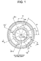
- Fig. 1 shows a schematic cross sectional view of the stator core 32 in the motor housing 15.
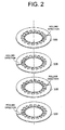
- the stator core 32 is formed, as shown in Fig. 2 , by laminating a plurality of stator core sheets 32B, each of which is blanked off from an electromagnetic steel sheet 160 ( Fig. 7 ).
- the electromagnetic steel sheet 160 is rolled to the predetermined thickness.
- the stator core sheets 32B are blanked off from the electromagnetic steel sheet 160 by using a die and laminated one on another thereby to form the laminated stator core 32.
- the outer circumference of the stator core 32 has a substantially circular shape as viewed in the axial direction of the stator core 32.
- the stator core 32 has as many as eighteen slots 32A.
- the stator windings 33 are not shown in Fig. 1 .
- stator core sheets 32B are alternately turned by an angle of 180 degrees with respect to the rolling direction of the steel sheet 160 from which the stator core sheets 32B are blanked off. That is, each stator core sheet 32B in the laminated stator core 32 is turned 180 degrees from its adjacent stator core sheet 32B with respect to the rolling direction of the steel sheet 160.
- Fig. 8 there exists a variation in the thickness of the steel sheet 160 in the direction perpendicular to the rolling direction of the steel sheet 160.
- the above laminating manner makes it possible to laminate the stator core sheets 32B accurately perpendicularly with respect to the end faces of the resulting stator core 32 and also reduce the variation in the height of the stator core 32.
- the laminated structure of the stator core 32 will be further described.
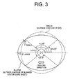
- the outside contour of the stator core sheet 32B blanked off from the steel sheet 160 by using a circular die or additionally heat treated by annealing thereafter becomes an ellipse or a curve, as shown in Fig. 3 .
- the ellipse resulting from the above blanking has its major axis in the rolling direction of the steel sheet 160 and the minor axis in the direction perpendicular to the above rolling direction.
- the outside contour of the blanked sheet (ellipse) and the outside contour of the blanking die (circle) intersect with each other at angles of about 45, 135, 225 and 315 degrees with respect to the major axis of the ellipse extending along the rolling direction of the steel sheet 160. Therefore, difference ⁇ (variation) in radius between the circle of the blanking die and the ellipse of the blanked stator core sheet 32B are smallest at the angular positions ⁇ of about 45, 135, 225 and 315 degrees of the stator core sheet 32B.
- stator core sheet 32B is subjected to very little or only a negligible influence of straining at the angular positions thereof about 45, 135, 225 and 315 degrees with respect to the major axis of the ellipse extending along the rolling direction.
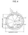
- Fig. 4 shows tolerance in diametral dimension of the stator core sheet of Fig. 3 .
- the chain line A shows the contour of a stator core sheet whose diameter is at the middle of the tolerance and which forms a circle with a diameter of A mm.
- the solid line B shows the contour of a stator core sheet whose diameter is at the upper tolerance and which forms a circle with a diameter of A+a mm.
- the solid line C shows the contour of a stator core sheet whose diameter is at the lower tolerance and which forms a circle with a diameter of A-a mm.
- the solid lines B and C show the circles representing the contour of the blanking dies with the upper and lower tolerances in diameter, respectively.
- the solid line D shows an elliptical contour of a blanked stator core sheet 32B.
- strain occurs in the steel sheet 160 in the rolling direction thereof, which is about 0.05% of the diameter of the blanked stator core sheets 32B. Strain also occurs in the direction perpendicular to the rolling direction, which is also about 0.05% of the diameter of the blanked sheets 32B.
- the length of the major axis of the ellipse shown by the solid line D of Fig. 4 in the rolling direction is A+0.0005A mm and the length of the minor axis of the same ellipse in the direction perpendicular to the rolling direction is A-0.0005A mm.
- the center of the ellipse shown by the solid line D coincides with the center of the circle shown by the chain line A.
- the length of 0.0005A is larger than that of a.
- FIG. 4 shows the stator core sheets having a diameter of A mm within the diametral tolerance of ⁇ a mm and a strain of 0.05%.
- the circle shown by the solid line B and the ellipse shown by the solid line D have in common the intersection points Pi1, Pi4, Pi5 and Pi8.
- the circle shown by the solid line C and the ellipse shown by the solid line D have in common the intersection points Pi2, Pi3, Pi6 and Pi7.
- the intersection points Pi1, Pi2, Pi3, Pi4, Pi5, Pi6, Pi7 and Pi8 are located at angular positions of ⁇ 1, ⁇ 2, ⁇ 3, ⁇ 4, ⁇ 5, ⁇ 6, ⁇ 7 and ⁇ 8 with respect to the major axis of the ellipse along the rolling direction, respectively.
- each of Figs. 3 and 4 shows the elliptical sheet for the stator core sheet 32B in an exaggerated manner for the sake of understanding of the present invention.
- the motor housing 15 of Fig. 1 has on the inner surface thereof projections 41A, 41B, 41C and 41D for fixing the stator core 32 in the motor housing 15.
- the projections 41A, 41B, 41C and 41 D are in contact at the distal end faces thereof with the outer circumferential surface of the stator core 32. That is, the stator core 32 is fixed in the motor housing 15 with at least a part of the outer circumferential surface of the stator core 32 in contact with the inner surface of the motor housing 15.
- the radial sides of the projections 41A, 41B, 41C and 41D are determined as follows. Referring to Figs. 1 and 4 , the first projection 41A is located such that its opposite radial sides form angles of ⁇ 1, ⁇ 2 with the major axis of the ellipse D. Similarly, the second projection 41B is located such that its opposite radial sides form angles of ⁇ 3, ⁇ 4 with the major axis of the ellipse D. The third projection 41C is located such that its opposite radial sides form angles of ⁇ 5, ⁇ 6 with the major axis of the ellipse D. The fourth projection 41 D is located such that its opposite radial sides form angles of ⁇ 7, ⁇ 8 with the major axis of the ellipse D.
- the stator core 32 is fixed in the motor housing 15 in such an angular position where the difference ⁇ in the diametral dimension of the outside contour between the blanking die and the blanked stator core sheet 32B is relatively small.
- the ranges of the fixing positions are set between ⁇ 1, ⁇ 2, between ⁇ 3, ⁇ 4, between ⁇ 5, ⁇ 6, and between ⁇ 7, 08 with respect to the major axis of the ellipse D.
- the stator core 32 is not fixed in the motor housing 15 in such an angular position where the difference ⁇ in the diametral dimension of the outside contour between the blanking die and the blanked stator core sheet 32B is relatively large.
- the ranges of the non-fixing positions are set between ⁇ 8, ⁇ 1, between ⁇ 4, ⁇ 5, between ⁇ 2, ⁇ 3, and between ⁇ 6, ⁇ 7 with respect to the major axis of the ellipse D.
- the fixed ranges ( ⁇ 1 ⁇ 2, ⁇ 3 ⁇ 4, ⁇ 5 ⁇ 6, ⁇ 7 ⁇ 8) change depending on allowable tolerance of the outside diameter of the stator core 32.
- the intersection points can be found from simultaneous equations of the circles B, C and the ellipse D of Fig. 4 and the information of such intersection points can be utilized in designing the projections on the inner surface of the motor housing 15. That is, the intersection points Pi1-Pi8 in Fig. 4 are the boundaries between the fixing positions and the non-fixing positions in fixing the stator core 32 to the motor housing 15.
- stator core 32 is fixed in the motor housing 15 in such an angular position where the difference ⁇ in the diametral dimension of the outside contour between the blanking die and the blanked stator core sheet 32B is relatively small. By so doing, the stator core 32 can be fixed securely to the motor housing 15 without being influenced by the strain of the stator core sheets 32B. Thus, it is unnecessary to adjust the die for controlling the diametral dimension of the outside contour of the stator core sheets.
- the outer circumferential surface of the motor housing 15 has a flat portion 15A formed by planing, on which the inverter 50 is mounted.
- the flatness of the flat portion 15A is not deteriorated in fixing the stator 31 in the motor housing 15. That is, although the inverter 50 mounted on the flat portion 15A whose flatness has been deteriorated may fail to be fixed to the flat portion 15A, such problem can be prevented in the present embodiment. Therefore, it is unnecessary to plane the motor housing 15 after making appropriate provision to prevent foreign matters from entering into the motor housing 15 after the stator 31 has been fixed in the motor housing 15.
- deformation of the motor housing 15 after assembling of the compressor 10 is reduced without affecting the flatness of the flat portion 15A on the motor housing 15 for mounting of the inverter 50. Therefore, planing the motor housing 15 after the stator 31 has been fixed in the motor housing 15 is not necessary.
- stator core sheets each having 18 slots are turned for each 60 degrees in stacking such sheets one on another thereby to form a laminated stator core 110. If such a stator core 110 is fixed in the housing 150 by shrink fit, the contact area between the inner surface of the housing 150 and the outer circumferential surface of the stator core 110 is smaller than that in the case where the axial contour of the stator core 110 is a true circle. As a result, there is fear that the stator 100 is rotated because the fixation of the stator 100 to the housing 150 fails to resist the torque of the motor operating under a high load.
- the stator core 32 is fixed in the motor housing 15 in such an angular position where the difference ⁇ in the diametral dimension of the outside contour between the blanking die and the blanked stator core sheet 32B is relatively small.
- the stator core sheets 32B are alternately turned by an angle of 180 degrees with respect to the rolling direction of the steel sheet 160 from which the stator core sheets 32B are blanked off.
- the present invention is not limited to the above-described embodiment, but it may be practiced as exemplified below.
- the strain of the blanked stator core sheet 32B in the rolling direction is responsible for the deformation of the motor housing 15.
- the range of fixing the stator core 32 in the motor housing 15 may be set in angular positions between ⁇ 1, ⁇ 4, and between ⁇ 5, 08 with respect to the rolling direction, as shown in Fig. 5 .
- the strained portion of the blanked stator core sheet 32B in the rolling direction may be unused in fixing to the motor housing 15.
- the above embodiment has been described for a case where the number of slots 32A of the stator core 32 is 18.
- the number of slots 32A is not limited to 18, but the stator core sheet may have any number of slots.
Landscapes
- Engineering & Computer Science (AREA)
- Power Engineering (AREA)
- Manufacturing & Machinery (AREA)
- Iron Core Of Rotating Electric Machines (AREA)
- Compressor (AREA)
- Manufacture Of Motors, Generators (AREA)
Applications Claiming Priority (1)
| Application Number | Priority Date | Filing Date | Title |
|---|---|---|---|
| JP2007280651A JP2009112096A (ja) | 2007-10-29 | 2007-10-29 | ステータコアの固定方法および電動圧縮機 |
Publications (2)
| Publication Number | Publication Date |
|---|---|
| EP2056428A2 true EP2056428A2 (de) | 2009-05-06 |
| EP2056428A3 EP2056428A3 (de) | 2013-04-24 |
Family
ID=40273419
Family Applications (1)
| Application Number | Title | Priority Date | Filing Date |
|---|---|---|---|
| EP08018807.1A Withdrawn EP2056428A3 (de) | 2007-10-29 | 2008-10-28 | Befestigungsverfahren eines Statorkörpers im Gehäuse und Verdichter mit einem solchen Stator |
Country Status (4)
| Country | Link |
|---|---|
| US (1) | US7767105B2 (de) |
| EP (1) | EP2056428A3 (de) |
| JP (1) | JP2009112096A (de) |
| CN (2) | CN102655360A (de) |
Cited By (1)
| Publication number | Priority date | Publication date | Assignee | Title |
|---|---|---|---|---|
| EP2448094A4 (de) * | 2009-06-23 | 2017-06-28 | Mitsui High-Tec, Inc. | Rotatorkern |
Families Citing this family (19)
| Publication number | Priority date | Publication date | Assignee | Title |
|---|---|---|---|---|
| JP4928978B2 (ja) * | 2007-02-23 | 2012-05-09 | 三菱重工業株式会社 | 電動圧縮機 |
| JP5987673B2 (ja) * | 2012-12-18 | 2016-09-07 | アイシン・エィ・ダブリュ株式会社 | 回転電機のステータコア |
| CN103887901A (zh) * | 2014-04-17 | 2014-06-25 | 林子进 | 一种利用取向硅钢片制作的高效率电机定子 |
| JP2015208164A (ja) * | 2014-04-22 | 2015-11-19 | サンデンホールディングス株式会社 | 電動圧縮機 |
| CN104209390A (zh) * | 2014-07-11 | 2014-12-17 | 宁波鸿达电机模具有限公司 | 铁芯冲槽槽形凸模磨加工结构及其加工工艺 |
| KR102202419B1 (ko) * | 2015-04-17 | 2021-01-13 | 한온시스템 주식회사 | 전동 압축기 |
| EP3342030B1 (de) * | 2015-08-27 | 2023-08-09 | BITZER Kühlmaschinenbau GmbH | Verdichter |
| GB2579358B (en) * | 2018-11-28 | 2021-06-09 | Jaguar Land Rover Ltd | A stator and a stator housing for an electric machine |
| JP7209260B2 (ja) | 2019-05-08 | 2023-01-20 | パナソニックIpマネジメント株式会社 | 固定子およびモータ |
| US11913473B2 (en) | 2020-03-17 | 2024-02-27 | Garrett Transportation I Inc | Compressor with electric motor coolant jacket having radial and axial portions |
| KR102538585B1 (ko) * | 2020-09-22 | 2023-05-31 | 에스트라오토모티브시스템 주식회사 | 모터의 고정자 및 이를 구비하는 전동압축기 |
| US11742717B2 (en) | 2020-11-17 | 2023-08-29 | Garrett Transportation I Inc | Motor cooling system for e-boosting device |
| US11689076B2 (en) | 2020-11-17 | 2023-06-27 | Garrett Transportation I Inc | Motor cooling system for e-boosting device |
| US11581791B2 (en) | 2020-11-17 | 2023-02-14 | Garrett Transportation Inc | Method of manufacturing e-boosting device |
| CN113364226B (zh) * | 2021-07-22 | 2022-09-02 | 哈尔滨电机厂有限责任公司 | 一种定子主铁心卧式叠装定位及压紧工艺方法 |
| CN113783388B (zh) * | 2021-10-14 | 2024-08-20 | 奇瑞安川电驱动系统有限公司 | 新能源汽车电机结构及新能源汽车电机装配方法 |
| JP2025044381A (ja) * | 2023-09-20 | 2025-04-02 | 株式会社ミクニ | 永久磁石埋込型モータ及びポンプ装置 |
| JP2025086366A (ja) * | 2023-11-28 | 2025-06-09 | 三菱重工サーマルシステムズ株式会社 | 電動圧縮機 |
| KR20250144700A (ko) * | 2024-03-27 | 2025-10-13 | 주식회사 아모텍 | 에르고 모션 시트용 일체형 에어 펌프 |
Citations (2)
| Publication number | Priority date | Publication date | Assignee | Title |
|---|---|---|---|---|
| JPH1024333A (ja) | 1996-07-10 | 1998-01-27 | Nippon Steel Corp | 無方向性電磁鋼板の打抜き方法 |
| JP2006299834A (ja) | 2005-04-15 | 2006-11-02 | Toyota Industries Corp | 電動コンプレッサ |
Family Cites Families (8)
| Publication number | Priority date | Publication date | Assignee | Title |
|---|---|---|---|---|
| EP0133859B1 (de) * | 1983-08-15 | 1987-01-21 | Essa Fabrique de Machines S.A. | Verfahren und Vorrichtung zur Herstellung von aus Blechlamellen mit Zentrumwinkelversetzung bestehenden Paketen von elektrischen Maschinen, insbesondere von Rotor- oder Statorpaketen |
| JPS61242725A (ja) * | 1985-04-19 | 1986-10-29 | Mitsui Haitetsuku:Kk | 積層鉄心の製造装置 |
| JP2002281698A (ja) | 2001-03-16 | 2002-09-27 | Toshiba Corp | 回転電機の固定子およびそれを用いた回転電機 |
| JP4036148B2 (ja) * | 2002-07-23 | 2008-01-23 | 株式会社豊田自動織機 | 電動モータ及び電動コンプレッサ |
| WO2005025037A1 (ja) * | 2003-09-04 | 2005-03-17 | Mitsubishi Denki Kabushiki Kaisha | 永久磁石式同期モータ及びその製造方法 |
| JP4269907B2 (ja) * | 2003-11-21 | 2009-05-27 | 株式会社豊田自動織機 | 密閉型電動圧縮機におけるステータコアの組み付け方法 |
| JP2005304150A (ja) | 2004-04-09 | 2005-10-27 | Mitsubishi Electric Corp | 回転電機 |
| JP2007244150A (ja) * | 2006-03-10 | 2007-09-20 | Toyota Industries Corp | 電動モータ及び電動圧縮機 |
-
2007
- 2007-10-29 JP JP2007280651A patent/JP2009112096A/ja active Pending
-
2008
- 2008-10-27 US US12/259,230 patent/US7767105B2/en not_active Expired - Fee Related
- 2008-10-28 CN CN201210132691.1A patent/CN102655360A/zh active Pending
- 2008-10-28 EP EP08018807.1A patent/EP2056428A3/de not_active Withdrawn
- 2008-10-28 CN CN200810172564.8A patent/CN101425727A/zh active Pending
Patent Citations (2)
| Publication number | Priority date | Publication date | Assignee | Title |
|---|---|---|---|---|
| JPH1024333A (ja) | 1996-07-10 | 1998-01-27 | Nippon Steel Corp | 無方向性電磁鋼板の打抜き方法 |
| JP2006299834A (ja) | 2005-04-15 | 2006-11-02 | Toyota Industries Corp | 電動コンプレッサ |
Cited By (1)
| Publication number | Priority date | Publication date | Assignee | Title |
|---|---|---|---|---|
| EP2448094A4 (de) * | 2009-06-23 | 2017-06-28 | Mitsui High-Tec, Inc. | Rotatorkern |
Also Published As
| Publication number | Publication date |
|---|---|
| US7767105B2 (en) | 2010-08-03 |
| US20090108697A1 (en) | 2009-04-30 |
| CN101425727A (zh) | 2009-05-06 |
| CN102655360A (zh) | 2012-09-05 |
| JP2009112096A (ja) | 2009-05-21 |
| EP2056428A3 (de) | 2013-04-24 |
Similar Documents
| Publication | Publication Date | Title |
|---|---|---|
| EP2056428A2 (de) | Befestigungsverfahren eines Statorkörpers im Gehäuse und Verdichter mit einem solchen Stator | |
| US7538468B2 (en) | Electric motor and electric compressor with improved housing and stator | |
| KR100192067B1 (ko) | 스크롤형 유체기계 | |
| US9765781B2 (en) | Scroll compressor | |
| US7768172B2 (en) | Permanent magnet type electric rotary machine and compressor using the same | |
| JP4849507B2 (ja) | 自己始動式同期電動機 | |
| US20040179967A1 (en) | Scroll compressor | |
| US20170284396A1 (en) | Electric compressor | |
| KR100675549B1 (ko) | 전동 콤프레서 | |
| US20170284395A1 (en) | Electric compressor | |
| JP2003219616A (ja) | 電動コンプレッサ用電動モータ、そのロータバランス調整方法及び電動コンプレッサ | |
| US20080118351A1 (en) | Stator Vane Of Turbo Molecular Pump | |
| EP3681013A1 (de) | Motor und verdichter damit | |
| US12206284B2 (en) | Electric compressor | |
| JP6956131B2 (ja) | スクロール型圧縮機 | |
| JP5370529B2 (ja) | 電動圧縮機 | |
| JP4253574B2 (ja) | 永久磁石式回転電機及びそれを用いた圧縮機 | |
| EP4407837B1 (de) | Elektrische drehmaschine, verdichter und kühlvorrichtung | |
| CN112602253A (zh) | 单齿段 | |
| JP6956127B2 (ja) | スクロール型圧縮機 | |
| CN107534342B (zh) | 旋转电动机以及压缩机 | |
| CN102192145B (zh) | 涡旋式流体机械及其组装方法 | |
| JP5506269B2 (ja) | 密閉型電動圧縮機 | |
| JP2026001142A (ja) | 電動機、圧縮機、及び機器 | |
| JP2026001142A5 (de) |
Legal Events
| Date | Code | Title | Description |
|---|---|---|---|
| PUAI | Public reference made under article 153(3) epc to a published international application that has entered the european phase |
Free format text: ORIGINAL CODE: 0009012 |
|
| 17P | Request for examination filed |
Effective date: 20081028 |
|
| AK | Designated contracting states |
Kind code of ref document: A2 Designated state(s): AT BE BG CH CY CZ DE DK EE ES FI FR GB GR HR HU IE IS IT LI LT LU LV MC MT NL NO PL PT RO SE SI SK TR |
|
| AX | Request for extension of the european patent |
Extension state: AL BA MK RS |
|
| PUAL | Search report despatched |
Free format text: ORIGINAL CODE: 0009013 |
|
| AK | Designated contracting states |
Kind code of ref document: A3 Designated state(s): AT BE BG CH CY CZ DE DK EE ES FI FR GB GR HR HU IE IS IT LI LT LU LV MC MT NL NO PL PT RO SE SI SK TR |
|
| AX | Request for extension of the european patent |
Extension state: AL BA MK RS |
|
| RIC1 | Information provided on ipc code assigned before grant |
Ipc: H02K 15/02 20060101ALI20130318BHEP Ipc: H02K 1/18 20060101AFI20130318BHEP Ipc: H02K 5/04 20060101ALN20130318BHEP |
|
| AKX | Designation fees paid |
Designated state(s): DE FR IT |
|
| 17Q | First examination report despatched |
Effective date: 20150216 |
|
| STAA | Information on the status of an ep patent application or granted ep patent |
Free format text: STATUS: THE APPLICATION IS DEEMED TO BE WITHDRAWN |
|
| 18D | Application deemed to be withdrawn |
Effective date: 20160616 |