EP2056157B1 - Anzeigevorrichtung - Google Patents
Anzeigevorrichtung Download PDFInfo
- Publication number
- EP2056157B1 EP2056157B1 EP08018081.3A EP08018081A EP2056157B1 EP 2056157 B1 EP2056157 B1 EP 2056157B1 EP 08018081 A EP08018081 A EP 08018081A EP 2056157 B1 EP2056157 B1 EP 2056157B1
- Authority
- EP
- European Patent Office
- Prior art keywords
- earphone
- display apparatus
- linear guide
- positioning mechanism
- locking
- Prior art date
- Legal status (The legal status is an assumption and is not a legal conclusion. Google has not performed a legal analysis and makes no representation as to the accuracy of the status listed.)
- Active
Links
- 230000007246 mechanism Effects 0.000 claims description 40
- 210000003128 head Anatomy 0.000 description 5
- 210000000613 ear canal Anatomy 0.000 description 4
- 210000005069 ears Anatomy 0.000 description 4
- 239000011521 glass Substances 0.000 description 4
- 238000003384 imaging method Methods 0.000 description 4
- 238000006073 displacement reaction Methods 0.000 description 2
- 230000005236 sound signal Effects 0.000 description 2
- 244000261422 Lysimachia clethroides Species 0.000 description 1
- 230000000694 effects Effects 0.000 description 1
- 230000004048 modification Effects 0.000 description 1
- 238000012986 modification Methods 0.000 description 1
- 230000001681 protective effect Effects 0.000 description 1
Images


Classifications
-
- G—PHYSICS
- G02—OPTICS
- G02C—SPECTACLES; SUNGLASSES OR GOGGLES INSOFAR AS THEY HAVE THE SAME FEATURES AS SPECTACLES; CONTACT LENSES
- G02C11/00—Non-optical adjuncts; Attachment thereof
- G02C11/06—Hearing aids
-
- G—PHYSICS
- G02—OPTICS
- G02B—OPTICAL ELEMENTS, SYSTEMS OR APPARATUS
- G02B27/00—Optical systems or apparatus not provided for by any of the groups G02B1/00 - G02B26/00, G02B30/00
- G02B27/01—Head-up displays
- G02B27/017—Head mounted
- G02B27/0176—Head mounted characterised by mechanical features
-
- G—PHYSICS
- G02—OPTICS
- G02C—SPECTACLES; SUNGLASSES OR GOGGLES INSOFAR AS THEY HAVE THE SAME FEATURES AS SPECTACLES; CONTACT LENSES
- G02C11/00—Non-optical adjuncts; Attachment thereof
- G02C11/10—Electronic devices other than hearing aids
-
- G—PHYSICS
- G02—OPTICS
- G02C—SPECTACLES; SUNGLASSES OR GOGGLES INSOFAR AS THEY HAVE THE SAME FEATURES AS SPECTACLES; CONTACT LENSES
- G02C5/00—Constructions of non-optical parts
- G02C5/22—Hinges
- G02C5/2263—Composite hinges, e.g. for varying the inclination of the lenses
-
- G—PHYSICS
- G02—OPTICS
- G02B—OPTICAL ELEMENTS, SYSTEMS OR APPARATUS
- G02B27/00—Optical systems or apparatus not provided for by any of the groups G02B1/00 - G02B26/00, G02B30/00
- G02B27/01—Head-up displays
- G02B27/017—Head mounted
- G02B2027/0178—Eyeglass type
Definitions
- the present invention relates to a display device with an image module for producing an image, a spectacle-like frame, which carries the image module and a front portion with a nose pad and two lateral ear hooks, which are attached to the front portion, and an attached via a positional mechanism on the frame earphone which is positionable in the state of the display device placed on the head of a user by means of the positional mechanism in front of an ear of the user.
- Such a display device is, for example, on US 2005/0168824 A1 known.
- the positional mechanism is designed as a bendable tube in order to introduce the earphone into the ear canal of a user's ear.
- Such a positional mechanism is only suitable for earphones (in-the-ear headphones) to be inserted into the auditory canal, since the position of the earphone is essentially ensured by inserting the earphone into the ear canal.
- a positional mechanics in the form of a bendable tube is not suitable because such a positional mechanics can not permanently ensure a set position. Even small forces are enough to change the position, which undesirably the acoustic signals of the earphone by the user worse or not at all can be detected.
- the US 7,147,324 B2 describes glasses with earphones.
- the earphones each have a hollow cylindrical connector which is guided on a linearly extending rod.
- a rotation about the longitudinal axis of the rod is possible.
- the JP 7-159720 shows a display device which includes a head ring for attachment to the head. Such a display device has a low wearing comfort, is difficult to set up and to wear.
- the object is achieved in a display device of the type mentioned above in that the positional mechanism is a linear guide, which is fastened via a lockable in different rotational positions swivel joint on the frame, and the earphone is arranged at the end remote from the rotary joint of the linear guide, wherein the Positional mechanics elastically biases the earphone in a direction transverse to the linear guide, so that an application to the ear at different head widths of the user is ensured.
- the positional mechanism is a linear guide, which is fastened via a lockable in different rotational positions swivel joint on the frame, and the earphone is arranged at the end remote from the rotary joint of the linear guide, wherein the Positional mechanics elastically biases the earphone in a direction transverse to the linear guide, so that an application to the ear at different head widths of the user is ensured.
- This design of the positional mechanism makes it possible to individually position the earphone at the ear of the user (and not in the ear) and hold it in this position. Furthermore, the display device can be made very compact while maintaining high comfort.
- the positional mechanism may further comprise a locking mechanism with which the set position of the earphone can be locked.
- the locking mechanism can in particular allow a separate locking or fixing of the rotary joint and the linear guide.
- the locking is possible, for example by means of friction and / or positive locking.
- the linear guide may be formed as a telescopic guide. This has the advantage that in the collapsed state of the telescopic guide this has a small footprint.
- the elastic bias can be realized by the inherent elasticity of the linear guide.
- the linear guide can have a latching mechanism with which different linear positions of the linear guide can be fixed. A fixation is also possible by means of a clamping element.
- the hinge of the positional mechanism can be attached to one of the earloop. This leads to a particularly space-saving design of the display device according to the invention.
- the display device can each have a positional mechanism with an earphone on each earhook. This allows a sound from both ears of the user.
- the two earphones can be independently positioned optimally to each ear.
- the earphones may in particular have a directional characteristic in the direction of the ears in the attached state of the display device.
- the image module for generating the image can generate the image as a virtual image so that it can perceive a user at a predetermined distance in front of the eye.
- the display device according to the invention can also be referred to as an HMD device (head-mounted display device).
- the image module can be formed as in known HMD devices.
- the image module may have a control device which, on the basis of predetermined image data, drives an image-generating element of the image module in such a way that the desired image is generated.
- the image module may further include imaging optics for imaging the image generated by the imaging element.
- the control device of the image module can also be used to control the earphones.
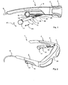
- the display device 1 comprises a spectacle-like frame 2 with a front section 3 and two earloops 4, 5.
- an image module containing, for each eye of a user who touches the display device 1, a display unit 7 with an image-forming element 8 and an imaging optics 9.
- the image module further includes a control unit 10 which drives the display units 7 on the basis of predetermined image data to generate the desired images.
- the image data can be supplied to the control unit 10 via the signal line S, for example, which runs through the right ear hook 5.
- each earphone 11, 12 via a positional mechanism 13, 14 is attached.
- the earphones 11, 12 and the associated position mechanisms 13, 14 are formed mirror-symmetrically to each other, only the earphone 11 with the positional mechanism 13 for the left earhook 4 will be described in detail below.
- the positional mechanism 13 is formed so that the earphone 11 relative to the earhook 4 pivoted downward (arrow P1 in Fig. 1 ) and in the longitudinal direction (arrow P2 in FIG Fig. 1 ) of the positional mechanism 13 is displaceable.
- the positional mechanism 13 a linear telescopic guide 15 which is rotatably mounted on the earloop 4.
- the telescopic guide 15 comprises a first telescopic unit 16 and a second telescopic unit 17 which can be displaced with respect to the latter in the longitudinal direction.
- the first telescope unit 16 comprises a telescopic guide 18 (FIG. Fig. 4 ), which is rotatably mounted on the earloop 4, and a locking plate 19 attached to the telescopic guide 18, which in its longitudinal direction a plurality of spaced-apart recesses 20 (FIG. Fig. 1 ) having.
- the second telescope unit 17 comprises a telescope housing 21 (FIG. Fig. 4 . 5 ), the inwardly facing side opening 22 is closed with a telescopic cover 23.
- the telescopic cover 23 has a latching element 24 (FIG. Fig. 1 . 5 ), which engages in the pushed onto the telescopic guide 18 state of the telescopic housing 21 in one of the recesses 20 of the locking plate 19.
- the latching element 24 is designed to be resilient so that it is biased against the detent plate 19 and thus a predetermined force is expended to move the second telescope unit 17 linear relative to the first telescopic unit 16. After the shift then the locking element 24 engages in the corresponding recess 20 and thus fixes the second telescopic unit 16th
- the telescopic housing 21 has at its rear end a receptacle for the earphone 11, which is inserted in this receptacle.
- the connection cable 25, the earphone 11 extends through a corresponding passage opening 26 (FIG. Fig. 5 ) in the first telescopic unit 16.
- the connection cable 25 is only in Fig. 4 indicated.
- the passage opening 26 is limited here by the telescopic guide 18 and the detent plate 19.
- the connecting cable 25, which extends through the through-hole 25, extends to the control unit 10 in the front section 3, so that the control unit 10 can also control the earphone 11 to offer the user of the display device 1 audio signals.
- the audio signals may in particular be beeps, texts and / or music.
- the connecting cable 25 is provided so that a length compensation takes place when the length of the telescopic guide is changed. This can e.g. be realized by at least one spiral cable section or a cable drum with bias.
- the front end 27 of the telescopic guide 18 is annular and rotatably mounted on an axis portion 28 of a bracket housing 29 of the earhook 4, wherein the bracket housing 29 is closed from the inside by a housing cover 30, which at the same time the front end 27 of the telescopic guide 18th secures in the axial direction.
- the axis portion 28 has a central bore 31 into which a fixing screw 32 is screwed through the housing cover 29 therethrough.
- a spring ring 33 is further arranged, which presses the front end 27 of the telescopic guide 18 against the housing cover 30, so that caused by the present friction, the weight of the telescopic guide 15 together with the earphone 11 no change in the rotational position. To change the rotational position another external force must be applied.
- the display device 1 When a user wears the display device 1, the two earloops 4 and 5 rest on the ears of the user and a nose pad 34 of the front portion 3 rests on the nose bridge of the user. The user thus wears the display device 1 as a pair of glasses and can position the earphones 4 and 5 just in front of his ears (in front of the external auditory canal) due to the degrees of freedom provided by the positional mechanisms 13, 14.
- the telescopic guide 15 is also still designed so that it is biased due to their inherent elasticity inwardly (ie towards the opposite earhook 5), whereby different head widths of the user can be compensated and at the same time it is ensured that the earphone 11 on the ear of the user or rests on the auricle in front of the external auditory canal.
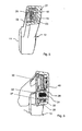
- a side view of the earhook 4 is shown together with the positional mechanism 13 and the earphone 11, in which the positional mechanism 13 with respect to the type of fixation the mutually displaceable telescopic units 16 and 17 differs from the previously described embodiment.
- a fixing screw 36 is screwed into the telescopic housing 29 from below. By tightening the fixing screw 36, it is possible to press the second telescopic unit 17 from the inside against the first telescopic unit 16 and thus to produce a frictional engagement in order to achieve the desired fixation of the two telescopic units 16 and 17.
- the fixing screw 36 can be tightened so that there is a frictional engagement, however, a displacement of the two telescopic units 16 and 17 relative to each other by pulling or pressing the earphone 11 in the longitudinal direction of the telescopic guide 15 permits. Without application of an external force but both telescopic units 16 and 17 are fixed to each other.
- a modification of the pivoting 40 is shown.
- an axially extending projection 37 is formed at the front end 27 of the telescopic guide 18.
- a locking ring 38 is rotatably disposed in the yoke housing 29, which has a plurality of spaced recesses 39 in the circumferential direction. Through the recesses 39 different pivot positions of the positional mechanism 13 are given, in which the projection 37 is in the respective recess 39 and thus causes a lock in the respective pivot position.
- a stop member 41 may be further provided, on which the projection 37 in the in Fig. 8 shown parking position of the positional mechanism 13 is applied to fix the positional mechanism 13 in this position.
- the telescopic guide can have such a backup by snapping in the position in which the telescopic guide is pushed together as much as possible.
- pivot position can be secured by clamping.
- a fixing element in the form of a gooseneck can be used to lock the set pivot position.
Landscapes
- Physics & Mathematics (AREA)
- Health & Medical Sciences (AREA)
- General Physics & Mathematics (AREA)
- Optics & Photonics (AREA)
- Ophthalmology & Optometry (AREA)
- Acoustics & Sound (AREA)
- General Health & Medical Sciences (AREA)
- Otolaryngology (AREA)
Description
- Die vorliegende Erfindung betrifft eine Anzeigevorrichtung mit einem Bildmodul zum Erzeugen eines Bildes, einem brillenartigen Gestell, das das Bildmodul trägt und einen Vorderabschnitt mit einer Nasenauflage sowie zwei seitliche Ohrbügel, die am Vorderabschnitt befestigt sind, aufweist, und einem über eine Positionsmechanik am Gestell befestigten Ohrhörer, der im auf den Kopf eines Benutzers aufgesetzten Zustand der Anzeigevorrichtung mittels der Positionsmechanik vor einem Ohr des Benutzers positionierbar ist.
- Eine solche Anzeigevorrichtung ist beispielsweise auf der
US 2005/0168824 A1 bekannt. Bei dieser Anzeigevorrichtung ist die Positionsmechanik jedoch als biegbares Rohr ausgebildet, um den Ohrhörer in den Gehörgang des Ohres eines Benutzers einführen zu können. Eine solche Positionsmechanik ist nur für in den Gehörgang einzuführende Ohrhörer (Im-Ohr-Kopfhörer) geeignet, da die Position des Ohrhörers im wesentlichen dadurch sichergestellt ist, daß der Ohrhörer in den Ohrkanal eingeführt ist. Für einen an das Ohr außen anzulegenden Ohrhörer ist eine Positionsmechanik in Form eines biegbaren Rohres nicht geeignet, da eine solche Positionsmechanik eine eingestellte Position nicht dauerhaft gewährleisten kann. Schon kleine Kräfte genügen, um die Position zu verändern, wodurch in unerwünschter Weise die akustischen Signale des Ohrhörers von dem Benutzer schlechter oder gar nicht mehr erfaßt werden können. - Auch bei der aus der
DE 196 24 184 A1 bekannten Brille mit Ohrhörer sind die Ohrhörer über biegbare Rohre an der Brille befestigt. Somit besteht wiederum das Problem, daß eine dauerhafte Positionierung am Ohr des Benutzers nicht gewährleistet werden kann. - Die
US 7,147,324 B2 beschreibt eine Brille mit Ohrhörem. Die Ohrhörer weisen jeweils ein hohlzylinderförmiges Verbindungsstück auf, das auf einer sich linear erstreckenden Stange geführt ist. Damit ist eine lineare Verschiebung und gleichzeitig eine Drehung um die Längsachse der Stange möglich. Dies führt jedoch zu dem Nachteil, daß die Positionierung am Ohr nur sehr schwer gesichert werden kann, da schon geringe Kräfte ausreichen, um eine Drehung um die Längsachse der Stange zu bewirken. Nachdem sich die Längsachse der Stange parallel zum Brillenbügel erstreckt, führt dies zu einem Abheben des Ohrhörers vom Ohr. - Die
JP 7-159720 - Die
US 5,703,670 beschreibt eine Schutzbrille mit Ohrstöpseln. - Ausgehend hiervon ist es Aufgabe der Erfindung, eine Anzeigevorrichtung der eingangs genannten Art so weiter zu bilden, daß der Ohrhörer für den jeweiligen Benutzer leicht am Ohr zu positionieren ist und diese Positionierung dauerhaft sichergestellt werden kann.
- Erfindungsgemäß wird die Aufgabe bei einer Anzeigevorrichtung der eingangs genannten Art dadurch gelöst, daß die Positionsmechanik eine Linearführung, die über ein in verschiedenen Drehstellungen verrastbares Drehgelenk am Gestell befestigt ist, aufweist und der Ohrhörer an dem dem Drehgelenk abgewandten Ende der Linearführung angeordnet ist, wobei die Positionsmechanik den Ohrhörer in einer Richtung quer zur Linearführung elastisch vorspannt, so dass ein Anlegen am Ohr bei unterschiedlichen Kopfbreiten der Benutzer gewährleistet wird.
- Durch diese Ausbildung der Positionsmechanik ist es möglich, den Ohrhörer individuell angepaßt am Ohr des Benutzers (und nicht im Ohr) zu positionieren und in dieser Position zu halten. Ferner kann die Anzeigevorrichtung sehr kompakt ausgebildet werden bei gleichzeitig hohem Tragekomfort.
- Die Positionsmechanik kann ferner einen Arretiermechanismus aufweisen, mit dem die eingestellte Position des Ohrhörers arretierbar ist.
- Der Arretiermechanismus kann insbesondere eine getrennte Arretierung bzw. Fixierung des Drehgelenkes und der Linearführung ermöglichen. Die Arretierung ist beispielsweise mittels Reibschluß und/oder Formschluß möglich.
- Ferner kann die Linearführung als Teleskopführung ausgebildet sein. Dies bringt den Vorteil mit sich, daß im zusammengeschobenen Zustand der Teleskopführung diese einen geringen Platzbedarf aufweist.
- Insbesondere kann die elastische Vorspannung durch die Eigenelastizität der Linearführung realisiert sein.
- Die Linearführung kann eine Rastmechanik aufweisen, mit der verschiedene Linearpositionen der Linearführung fixiert werden können. Eine Fixierung ist auch mittels eines Klemmelementes möglich.
- Insbesondere kann das Drehgelenk der Positionsmechanik an einem der Ohrbügel befestigt sein. Dies führt zu einer besonders platzsparenden Ausbildung der erfindungsgemäßen Anzeigevorrichtung.
- Ferner kann die Anzeigevorrichtung an jedem Ohrbügel jeweils eine Positionsmechanik mit einem Ohrhörer aufweisen. Damit ist eine Beschallung von beiden Ohren des Benutzers möglich. Die beiden Ohrhörer können voneinander unabhängig optimal zum jeweiligen Ohr positioniert werden.
- Die Ohrhörer können insbesondere eine Richtcharakteristik in Richtung zu den Ohren im aufgesetzten Zustand der Anzeigevorrichtung aufweisen.
- Das Bildmodul zum Erzeugen des Bildes kann das Bild als virtuelles Bild so erzeugen, daß es ein Benutzer in einem vorbestimmten Abstand vor dem Auge wahrnehmen kann.
- Die erfindungsgemäße Anzeigevorrichtung kann auch als HMD-Vorrichtung bezeichnet werden (Head-Mounted-Display-Vorrichtung). Insbesondere kann das Bildmodul wie bei bekannten HMD-Vorrichtungen ausgebildet werden.
- Ferner kann das Bildmodul eine Steuereinrichtung aufweisen, die auf der Basis vorgegebener Bilddaten ein bilderzeugendes Element des Bildmoduls so ansteuert, daß das gewünschte Bild erzeugt wird. Das Bildmodul kann ferner einer Abbildungsoptik zur Abbildung des mittels dem bilderzeugenden Element erzeugten Bildes enthalten.
- Die Steuereinrichtung des Bildmoduls kann auch zur Steuerung der Ohrhörer benutzt werden.
- Es versteht sich, daß die vorstehend genannten und die nachstehend noch zu erläuternden Merkmale nicht nur in den angegebenen Kombinationen, sondern auch in anderen Kombinationen oder in Alleinstellung einsetzbar sind, ohne den Rahmen der vorliegenden Erfindung zu verlassen.
- Nachfolgend wird die Erfindung beispielsweise anhand der beigefügten Zeichnungen, die auch erfindungswesentliche Merkmale offenbaren, noch näher erläutert. Es zeigen:
-
Fig. 1 eine Seitenansicht einer ersten Ausführungsform der erfindungsgemäßen Anzeigevorrichtung; -
Fig. 2 eine perspektivische Ansicht der Anzeigevorrichtung vonFig.1 ; -
Fig. 3 eine stark vereinfachte Draufsicht zur Erläuterung des Bildmoduls der Anzeigevorrichtung vonFig. 1 ; -
Fig. 4 eine perspektivische Ansicht der Anzeigevorrichtung vonFig. 1 , wobei der linke Brillenbügel in einer Explosionsdarstellung gezeigt ist; -
Fig. 5 eine Schnittdarstellung der Positionsmechanik 13; -
Fig. 6 eine Schnittdarstellung des Drehgelenkes 40 der Positionsmechanik 13; -
Fig. 7 eine Seitenansicht des linken Ohrbügels zusammen mit der Positionsmechanik zur Erläuterung einer weiteren Ausführungsform der erfindungsgemäßen Anzeigevorrichtung, und -
Fig. 8 eine Seitenansicht des linken Ohrbügels zusammen mit der Positionsmechanik 13, wobei der Gehäusedeckel entfernt ist. - Bei der in den
Figuren 1 bis 6 gezeigten Ausführungsform umfaßt die erfindungsgemäße Anzeigevorrichtung 1 ein brillenartiges Gestell 2 mit einem Vorderabschnitt 3 und zwei Ohrbügeln 4, 5. - Im Vorderabschnitt 3 ist, wie in der schematischen Darstellung von
Fig. 3 ersichtlich ist, ein Bildmodul enthalten, das für jedes Auge eines Benutzers, der die Anzeigevorrichtung 1 aufsetzt, eine Anzeigeeinheit 7 mit einem bilderzeugenden Element 8 und einer Abbildungsoptik 9 aufweist. Das Bildmodul enthält ferner eine Steuereinheit 10, die die Anzeigeeinheiten 7 auf der Basis vorgegebener Bilddaten ansteuert, um die gewünschten Bilder zu erzeugen. Die Bilddaten können z.B. über die Signalleitung S, die durch den rechten Ohrbügel 5 verläuft, der Steuereinheit 10 zugeführt werden. - An jedem der Ohrbügel 4, 5 ist jeweils ein Ohrhörer 11, 12 über eine Positionsmechanik 13, 14 befestigt. Nachdem die Ohrhörer 11, 12 und die zugeordneten Positionsmechaniken 13, 14 zueinander spiegelsymmetrisch ausgebildet sind, wird nachfolgend im Detail nur der Ohrhörer 11 mit der Positionsmechanik 13 für den linken Ohrbügel 4 beschrieben.
- Wie am besten aus
Fig. 1 und 2 ersichtlich ist, ist die Positionsmechanik 13 so ausgebildet, daß der Ohrhörer 11 relativ zum Ohrbügel 4 nach unten geschwenkt (Pfeil P1 inFig. 1 ) werden kann und in Längsrichtung (Pfeil P2 inFig. 1 ) der Positionsmechanik 13 verschiebbar ist. - Dazu weist die Positionsmechanik 13 eine lineare Teleskopführung 15 auf, die drehbar am Ohrbügel 4 befestigt ist.
- Die Teleskopführung 15 umfaßt eine erste Teleskopeinheit 16 und eine gegenüber dieser in Längsrichtung verschiebbare zweite Teleskopeinheit 17. Die erste Teleskopeinheit 16 umfaßt eine Teleskopführung 18 (
Fig. 4 ), die drehbar am Ohrbügel 4 befestigt ist, sowie eine an der Teleskopführung 18 befestigte Rastplatte 19, die in ihrer Längsrichtung mehrere voneinander beabstandete Vertiefungen 20 (Fig. 1 ) aufweist. - Die zweite Teleskopeinheit 17 umfaßt ein Teleskopgehäuse 21 (
Fig. 4 ,5 ), dessen nach innen weisende Seitenöffnung 22 mit einer Teleskopabdeckung 23 verschlossen ist. Die Teleskopabdeckung 23 weist ein Rastelement 24 (Fig. 1 ,5 ) auf, das im auf die Teleskopführung 18 aufgeschobenen Zustand des Teleskopgehäuses 21 in eine der Vertiefungen 20 der Rastplatte 19 eingreift. Das Rastelement 24 ist derart elastisch ausgebildet, daß es gegen die Rastplatte 19 vorgespannt ist und somit eine vorbestimmte Kraft aufzuwenden ist, um die zweite Teleskopeinheit 17 linear relativ zur ersten Teleskopeinheit 16 zu verschieben. Nach erfolgter Verschiebung rastet dann das Rastelement 24 in die entsprechende Vertiefung 20 ein und fixiert somit die zweite Teleskopeinheit 16. - Das Teleskopgehäuse 21 weist an seinem hinteren Ende eine Aufnahme für den Ohrhörer 11 auf, der in dieser Aufnahme eingesetzt ist. Das Anschlußkabel 25, des Ohrhörers 11 verläuft durch eine entsprechende Durchgangsöffnung 26 (
Fig. 5 ) in der ersten Teleskopeinheit 16. Das Anschlußkabel 25 ist nur inFig. 4 angedeutet. Die Durchgangsöffnung 26 ist hier durch die Teleskopführung 18 und die Rastplatte 19 begrenzt. Das Anschlußkabel 25, das durch die Durchgangsöffnung 25 verläuft, erstreckt sich bis zur Steuereinheit 10 im Vorderabschnitt 3, so daß die Steuereinheit 10 auch den Ohrhörer 11 ansteuern kann, um dem Benutzer der Anzeigevorrichtung 1 Audiosignale darzubieten. Bei den Audiosignalen kann es sich insbesondere um Signaltöne, Texte und/oder um Musik handeln. - Das Anschlußkabel 25 ist so vorgesehen, daß ein Längenausgleich erfolgt, wenn die Länge der Teleskopführung verändert wird. Dies kann z.B. durch zumindest einen spiralförmigen Kabelabschnitt oder einer Kabeltrommel mit Vorspannung realisiert werden.
- Wie am besten in
Fig. 4 und6 ersichtlich ist, ist das vordere Ende 27 der Teleskopführung 18 ringförmig ausgebildet und drehbar auf einem Achsenabschnitt 28 eines Bügelgehäuses 29 des Ohrbügels 4 gelagert, wobei das Bügelgehäuse 29 von der Innenseite durch einen Gehäusedeckel 30 verschlossen ist, der zugleich das vordere Ende 27 der Teleskopführung 18 in axialer Richtung sichert. Dazu weist der Achsenabschnitt 28 eine Mittelbohrung 31 auf, in die eine Fixierschraube 32 durch den Gehäusedeckel 29 hindurch eingeschraubt ist. In dem Bügelgehäuse 29 ist ferner ein Federring 33 angeordnet, der das vordere Ende 27 der Teleskopführung 18 gegen den Gehäusedeckel 30 drückt, so daß durch den vorliegenden Reibschluß das Eigengewicht der Teleskopführung 15 zusammen mit dem Ohrhörer 11 keine Änderung der Drehstellung bewirkt. Zu einer Änderung der Drehstellung muß eine weitere externe Kraft angewendet werden. Das vordere Ende 27 der Teleskopführung bildet zusammen mit dem Achsenabschnitt 18 ein Drehgelenk 40. - Durch die Positionsmechanik 13 ist es somit möglich, den Ohrhörer 11 gegenüber dem Ohrbügel 4 zu verschwenken (Drehgelenk 40) und aufgrund der linearen Teleskopführung den Abstand des Ohrhörers 11 von der Drehachse der Positionsmechanik 13 bzw. vom Drehgelenk 40 zu verändern. Damit ist eine Positionierung des Ohrhörers 11 in zwei Freiheitsgraden möglich.
- Wenn ein Benutzer die Anzeigevorrichtung 1 trägt, liegen die beiden Ohrbügel 4 und 5 auf den Ohren des Benutzers auf und liegt eine Nasenauflage 34 des Vorderabschnitts 3 auf dem Nasenrücken des Benutzers auf. Der Benutzer trägt somit die Anzeigevorrichtung 1 wie eine Brille und kann die Ohrhörer 4 und 5 aufgrund den durch die Positionsmechaniken 13, 14 bereitgestellten Freiheitsgraden genau vor seinen Ohren (vor dem äußeren Gehörgang) positionieren.
- Die Teleskopführung 15 ist ferner noch so ausgebildet, daß sie aufgrund ihrer Eigenelastizität nach innen (also zum gegenüber liegenden Ohrbügel 5 hin) vorgespannt ist, wodurch unterschiedliche Kopfbreiten des Benutzers ausgeglichen werden können und gleichzeitig sichergestellt ist, daß der Ohrhörer 11 auf dem Ohr des Benutzers bzw. auf der Ohrmuschel vor dem äußeren Gehörgang aufliegt.
- In
Fig. 7 ist eine Seitenansicht des Ohrbügels 4 zusammen mit der Positionsmechanik 13 und dem Ohrhörer 11 gezeigt, bei der sich die Positionsmechanik 13 bezüglich der Art der Fixierung der gegeneinander verschiebbaren Teleskopeinheiten 16 und 17 von der bisher beschriebenen Ausführungsform unterscheidet. Wie inFig. 7 angedeutet ist, ist in das Teleskopgehäuse 29 von unten eine Fixierschraube 36 eingeschraubt. Durch Anziehen der Fixierschraube 36 ist es möglich, die zweite Teleskopeinheit 17 von innen gegen die erste Teleskopeinheit 16 zu drücken und somit einen Reibschluß zu erzeugen, um die gewünschte Fixierung der beiden Teleskopeinheiten 16 und 17 zu erzielen. Die Fixierschraube 36 kann dabei so angezogen werden, daß ein Reibschluß vorliegt, der jedoch ein Verschieben der beiden Teleskopeinheiten 16 und 17 relativ zueinander durch Ziehen oder Drücken am Ohrhörer 11 in Längsrichtung der Teleskopführung 15 zuläßt. Ohne Anwendung einer externen Kraft sind aber beide Teleskopeinheiten 16 und 17 zueinander fixiert. - In
Fig. 8 ist eine Abwandlung des Drehgelenkt 40 dargestellt. In diesem Fall ist an dem vorderen Ende 27 der Teleskopführung 18 ein sich axial erstreckender Vorsprung 37 ausgebildet. Als Gegenstück zu dem Vorsprung 37 ist im Bügelgehäuse 29 drehfest ein Rastring 38 angeordnet, der in Umfangsrichtung eine Vielzahl von voneinander beabstandeten Vertiefungen 39 aufweist. Durch die Vertiefungen 39 sind verschiedene Schwenkstellungen der Positionsmechanik 13 vorgegeben, bei denen der Vorsprung 37 in die jeweilige Vertiefung 39 einsteht und somit eine Arretierung in der jeweiligen Schwenkstellung bewirkt. - In dem Bügelgehäuse 29 kann ferner ein Anschlagelement 41 vorhanden sein, an dem der Vorsprung 37 in der in
Fig. 8 gezeigten Parkstellung der Positionsmechanik 13 anliegt, um die Positionsmechanik 13 in dieser Stellung zu fixieren. Ferner kann auch die Teleskopführung eine solche Sicherung durch Einrasten in der Stellung aufweisen, in der die Teleskopführung so weit wie möglich zusammengeschoben ist. - Natürlich ist es möglich, den Rastring 38 am vorderen Ende 27 der Teleskopführung 18 vorzusehen und den Vorsprung 37 mit dem Bügelgehäuse 29 zu verbinden.
- Ferner kann Schwenkstellung durch Klemmen gesichert werden. Auch kann ein Fixierelement in Form eines Schwanenhalses verwendet werden, um die eingestellte Schwenkstellung zu arretieren.
Claims (9)
- Anzeigevorrichtung (1) mit
einem Bildmodul zum Erzeugen eines Bildes,
einem brillenartigen Gestell (2), das das Bildmodul trägt und einen Vorderabschnitt (3) mit einer Nasenauflage (34) sowie zwei seitliche Ohrbügel (4, 5), die am Vorderabschnitt (3) befestigt sind, aufweist,
und einem über eine Positionsmechanik (13, 14) am Gestell (2) befestigten Ohrhörer (11, 12), der im auf den Kopf eines Benutzers aufgesetzten Zustand der Anzeigevorrichtung mittels der Positionsmechanik (13, 14) vor einem Ohr des Benutzers positionierbar ist,
dadurch gekennzeichnet, daß die Positionsmechanik (13, 14) eine Linearführung (15), die über ein in verschiedenen Drehstellungen verrastbares Drehgelenk (40) am Gestell (2) befestigt ist, aufweist und der Ohrhörer (11, 12) an dem dem Drehgelenk (40) abgewandten Ende der Linearführung (15) angeordnet ist, wobei die Positionsmechanik (13, 14) den Ohrhörer (11, 12) in einer Richtung quer zur Linearführung (15) elastisch vorspannt, so dass ein Anlegen am Ohr bei unterschiedlichen Kopfbreiten der Benutzer gewährleistet wird. - Anzeigevorrichtung (1) nach Anspruch 1, gekennzeichnet durch einen Arretiermechanismus, mit dem die mittels der Positionsmechanik (13, 14) eingestellte Position des Ohrhörers (4, 5) arretierbar ist.
- Anzeigevorrichtung (1) nach Anspruch 2, dadurch gekennzeichnet, daß mittels dem Arretiermechanismus das Drehgelenk (40) und die Linearführung (15) voneinander unabhängig arretierbar sind.
- Anzeigevorrichtung (1) nach Anspruch 2 oder 3, dadurch gekennzeichnet, daß die Arretierung durch Form- und/oder Reibschluß erfolgt.
- Anzeigevorrichtung (1) nach einem der obigen Ansprüche, dadurch gekennzeichnet, daß die Linearführung (15) eine Rastmechanik (24, 20) aufweist.
- Anzeigevorrichtung (1) nach einem der obigen Ansprüche, dadurch gekennzeichnet, daß die elastische Vorspannung durch die Eigenelastizität der Linearführung (15) realisiert ist.
- Anzeigevorrichtung (1) nach einem der obigen Ansprüche, dadurch gekennzeichnet, daß die Linearführung (15) ein Klemmelement zu Fixierung der mittels der Linearführung (15) eingestellten Linearposition aufweist.
- Anzeigevorrichtung (1) nach einem der obigen Ansprüche, dadurch gekennzeichnet, daß das Drehgelenk (40) der Positionsmechanik (13, 14) an einem der Ohrbügel (4, 5) befestigt ist.
- Anzeigevorrichtung (1) nach einem der obigen Ansprüche, dadurch gekennzeichnet, daß an jedem Ohrbügel (4, 5) jeweils eine Positionsmechanik (13, 14) mit einem Ohrhörer (11, 12) befestigt ist.
Applications Claiming Priority (1)
| Application Number | Priority Date | Filing Date | Title |
|---|---|---|---|
| DE102007051959A DE102007051959A1 (de) | 2007-10-29 | 2007-10-29 | Anzeigevorrichtung |
Publications (2)
| Publication Number | Publication Date |
|---|---|
| EP2056157A1 EP2056157A1 (de) | 2009-05-06 |
| EP2056157B1 true EP2056157B1 (de) | 2014-10-01 |
Family
ID=40227813
Family Applications (1)
| Application Number | Title | Priority Date | Filing Date |
|---|---|---|---|
| EP08018081.3A Active EP2056157B1 (de) | 2007-10-29 | 2008-10-15 | Anzeigevorrichtung |
Country Status (3)
| Country | Link |
|---|---|
| US (1) | US20090243964A1 (de) |
| EP (1) | EP2056157B1 (de) |
| DE (1) | DE102007051959A1 (de) |
Cited By (1)
| Publication number | Priority date | Publication date | Assignee | Title |
|---|---|---|---|---|
| KR20200097360A (ko) * | 2019-02-07 | 2020-08-19 | 김현용 | 헤드셋용 안경 |
Families Citing this family (18)
| Publication number | Priority date | Publication date | Assignee | Title |
|---|---|---|---|---|
| CN108873372B (zh) * | 2018-08-24 | 2024-06-14 | 深圳市韶音科技有限公司 | 一种铰链及眼镜 |
| US11611834B2 (en) | 2011-12-23 | 2023-03-21 | Shenzhen Shokz Co., Ltd. | Bone conduction speaker and compound vibration device thereof |
| CN103926712B (zh) * | 2013-01-10 | 2016-05-11 | 荆延杰 | 具有通话功能的眼镜 |
| US11558698B2 (en) | 2014-01-06 | 2023-01-17 | Shenzhen Shokz Co., Ltd. | Systems and methods for suppressing sound leakage |
| US11582565B2 (en) | 2014-01-06 | 2023-02-14 | Shenzhen Shokz Co., Ltd. | Systems and methods for suppressing sound leakage |
| CN104793351A (zh) * | 2014-01-16 | 2015-07-22 | 荆延杰 | 外翻听筒式无线耳机眼镜 |
| CN104793352A (zh) * | 2014-01-16 | 2015-07-22 | 荆延杰 | 弹簧听筒式无线耳机眼镜 |
| DE102014207497A1 (de) * | 2014-04-17 | 2015-10-22 | Carl Zeiss Ag | Anzeigevorrichtung und Einstellverfahren für eine solche Anzeigevorrichtung |
| JP6528498B2 (ja) * | 2015-03-25 | 2019-06-12 | セイコーエプソン株式会社 | 頭部搭載型ディスプレイ |
| KR101990724B1 (ko) * | 2015-03-27 | 2019-06-18 | 선전 로욜 테크놀로지스 컴퍼니 리미티드 | 모듈화 헤드 장착 디스플레이 디바이스와, 조립 및 분해 모듈 |
| US10459236B2 (en) * | 2016-12-09 | 2019-10-29 | Lg Electronics Inc. | Head-mounted display device with earbud holder |
| US11112612B2 (en) * | 2017-01-24 | 2021-09-07 | Sony Corporation | Hinge mechanism and head-mounted display including this hinge mechanism |
| CN206975323U (zh) * | 2017-06-30 | 2018-02-06 | 深圳市大疆创新科技有限公司 | 头戴式显示设备 |
| CN108490639B (zh) * | 2018-05-31 | 2024-06-21 | 北京达佳互联信息技术有限公司 | 固定支架、眼镜架和智能眼镜 |
| CN113330353B (zh) | 2019-01-17 | 2023-07-28 | 苹果公司 | 头戴式显示器及其面部界面 |
| KR102077483B1 (ko) * | 2019-05-24 | 2020-02-14 | 박태수 | 안경에 탈부착 가능한 탈부착 모듈 |
| WO2020242155A1 (ko) * | 2019-05-24 | 2020-12-03 | 박태수 | 안경에 탈부착 가능한 탈부착 모듈 |
| CN113189778B (zh) * | 2021-04-27 | 2023-12-01 | 歌尔股份有限公司 | 镜腿结构、及其制备方法和头戴式显示设备 |
Citations (3)
| Publication number | Priority date | Publication date | Assignee | Title |
|---|---|---|---|---|
| EP0353930A1 (de) * | 1988-08-02 | 1990-02-07 | Hellberg Protection Ab | Augen- und Gehörschutz |
| DE9301529U1 (de) * | 1993-02-04 | 1993-03-25 | Fa. Carl Zeiss, 7920 Heidenheim | Fassung für eine Fernrohrbrille bzw. Fernrohrlupenbrille |
| US20060055875A1 (en) * | 2004-08-26 | 2006-03-16 | All-Logic Int. Co., Ltd. | Eyeglasses with adjustable temples |
Family Cites Families (18)
| Publication number | Priority date | Publication date | Assignee | Title |
|---|---|---|---|---|
| US35051A (en) | 1862-04-22 | Improvement in apparatus for cooling and freezing | ||
| US4901355A (en) * | 1986-08-04 | 1990-02-13 | Moore Michael R | Combination multiple supported variable position audio intake control devices |
| CA2059597A1 (en) * | 1991-01-22 | 1992-07-23 | Paul A. Vogt | Radio eyewear |
| US5289592A (en) * | 1992-04-03 | 1994-03-01 | Paivarinta Reijo J | Eye glass holder |
| US5815126A (en) * | 1993-10-22 | 1998-09-29 | Kopin Corporation | Monocular portable communication and display system |
| US6424321B1 (en) * | 1993-10-22 | 2002-07-23 | Kopin Corporation | Head-mounted matrix display |
| US6448944B2 (en) * | 1993-10-22 | 2002-09-10 | Kopin Corporation | Head-mounted matrix display |
| US7310072B2 (en) * | 1993-10-22 | 2007-12-18 | Kopin Corporation | Portable communication display device |
| JPH07159720A (ja) | 1993-12-10 | 1995-06-23 | Sony Corp | 光学視覚装置 |
| US5903395A (en) * | 1994-08-31 | 1999-05-11 | I-O Display Systems Llc | Personal visual display system |
| US5991085A (en) * | 1995-04-21 | 1999-11-23 | I-O Display Systems Llc | Head-mounted personal visual display apparatus with image generator and holder |
| DE19624184A1 (de) | 1996-06-18 | 1998-01-02 | Elster Guenther | Brille mit Empfangseinrichtung |
| US5703670A (en) * | 1996-11-19 | 1997-12-30 | Callard; Shawn R. | Earplugs adapted to eyeglasses and combination thereof |
| US7461936B2 (en) * | 2000-06-02 | 2008-12-09 | Oakley, Inc. | Eyeglasses with detachable adjustable electronics module |
| US8482488B2 (en) * | 2004-12-22 | 2013-07-09 | Oakley, Inc. | Data input management system for wearable electronically enabled interface |
| MXPA05001079A (es) * | 2002-07-26 | 2005-06-03 | Oakley Inc | Audifonos interactivos inalambricos. |
| US6776483B1 (en) * | 2003-01-29 | 2004-08-17 | Jin-Feng Wu | Spectacles having angle adjustable function |
| US20050168824A1 (en) | 2004-01-07 | 2005-08-04 | Interactive Imaging Systems, Inc. | Binocular virtual display imaging device |
-
2007
- 2007-10-29 DE DE102007051959A patent/DE102007051959A1/de not_active Ceased
-
2008
- 2008-10-15 EP EP08018081.3A patent/EP2056157B1/de active Active
- 2008-10-29 US US12/260,597 patent/US20090243964A1/en not_active Abandoned
Patent Citations (3)
| Publication number | Priority date | Publication date | Assignee | Title |
|---|---|---|---|---|
| EP0353930A1 (de) * | 1988-08-02 | 1990-02-07 | Hellberg Protection Ab | Augen- und Gehörschutz |
| DE9301529U1 (de) * | 1993-02-04 | 1993-03-25 | Fa. Carl Zeiss, 7920 Heidenheim | Fassung für eine Fernrohrbrille bzw. Fernrohrlupenbrille |
| US20060055875A1 (en) * | 2004-08-26 | 2006-03-16 | All-Logic Int. Co., Ltd. | Eyeglasses with adjustable temples |
Cited By (2)
| Publication number | Priority date | Publication date | Assignee | Title |
|---|---|---|---|---|
| KR20200097360A (ko) * | 2019-02-07 | 2020-08-19 | 김현용 | 헤드셋용 안경 |
| KR102166479B1 (ko) | 2019-02-07 | 2020-10-16 | 김현용 | 헤드셋용 안경 |
Also Published As
| Publication number | Publication date |
|---|---|
| EP2056157A1 (de) | 2009-05-06 |
| DE102007051959A1 (de) | 2009-05-14 |
| US20090243964A1 (en) | 2009-10-01 |
Similar Documents
| Publication | Publication Date | Title |
|---|---|---|
| EP2056157A1 (de) | Anzeigevorrichtung | |
| DE69421061T2 (de) | Auf dem kopf zu tragende bildanzeigevorrichtung mit aufblasbaren elementen | |
| DE69217905T2 (de) | Brillenartige Bildanzeige-Vorrichtung | |
| EP2116100B1 (de) | Ohrhörer | |
| DE202007019108U1 (de) | Mechanisches Universalscharnier | |
| AT505258B1 (de) | Adapter zur verbindung eines optischen aufzeichnungsgeräts mit einem beobachtungsgerät | |
| DE10311972A1 (de) | HMD-Vorrichtung | |
| DE102008030497B4 (de) | Hörer und Headset | |
| EP2332342A1 (de) | In-ohr hörer und erweiterungsadapter | |
| DE202009014856U1 (de) | Kopfhörer | |
| EP3087757A1 (de) | Kopfhörer | |
| DE102017120603A1 (de) | Einstellbare Kopfhörer | |
| DE102014107938B4 (de) | Anzeigevorrichtung | |
| EP1967893B1 (de) | Knochenleitungsmodul zum Aufsetzen auf eine Brille, Knochenleitungshörgerät-Brille mit einem derartigen Modul und Verfahren zu ihrer Herstellung | |
| EP1847868B1 (de) | Hinter-dem-Ohr-Hörgerät einschließlich Brillenadapter mit dünnem Schallschlauch | |
| EP2156242A1 (de) | Augenmuschel | |
| EP2058689B1 (de) | Anzeigevorrichtung | |
| DE102008049338A1 (de) | Anzeigevorrichtung | |
| DE202006003427U1 (de) | Sichtgerät | |
| DE102004026825A1 (de) | Modulares System zum Aufbau einer auf dem Kopf eines Benutzers zu tragenden Anzeigevorrichtung | |
| WO2019096972A1 (de) | Brillenglashalter | |
| DE202008003015U1 (de) | Mobile Telekommunikationseinrichtung zum Übertragen und Übersetzen von Informationen | |
| DE102007060233B4 (de) | Hörer, Headset und Gehörschutz | |
| DE60005173T2 (de) | Justierbare halterung wie beispielsweise eine ohr-halterung | |
| DE102006001505A1 (de) | HMD-Vorrichtung |
Legal Events
| Date | Code | Title | Description |
|---|---|---|---|
| PUAI | Public reference made under article 153(3) epc to a published international application that has entered the european phase |
Free format text: ORIGINAL CODE: 0009012 |
|
| AK | Designated contracting states |
Kind code of ref document: A1 Designated state(s): AT BE BG CH CY CZ DE DK EE ES FI FR GB GR HR HU IE IS IT LI LT LU LV MC MT NL NO PL PT RO SE SI SK TR |
|
| AX | Request for extension of the european patent |
Extension state: AL BA MK RS |
|
| 17P | Request for examination filed |
Effective date: 20091103 |
|
| AKX | Designation fees paid |
Designated state(s): DE FR GB |
|
| RBV | Designated contracting states (corrected) |
Designated state(s): DE FR GB |
|
| RIN1 | Information on inventor provided before grant (corrected) |
Inventor name: BECK, KLAUS Inventor name: WEBER, PETER Inventor name: ROTTENKOLBER, BIRGIT Inventor name: ENGLER, BERTHOLD Inventor name: JARVIS, NATHANIEL A. Inventor name: KNOOP, CHRISTIAN |
|
| 17Q | First examination report despatched |
Effective date: 20120410 |
|
| 17Q | First examination report despatched |
Effective date: 20120419 |
|
| GRAP | Despatch of communication of intention to grant a patent |
Free format text: ORIGINAL CODE: EPIDOSNIGR1 |
|
| INTG | Intention to grant announced |
Effective date: 20140428 |
|
| GRAS | Grant fee paid |
Free format text: ORIGINAL CODE: EPIDOSNIGR3 |
|
| GRAA | (expected) grant |
Free format text: ORIGINAL CODE: 0009210 |
|
| AK | Designated contracting states |
Kind code of ref document: B1 Designated state(s): DE FR GB |
|
| REG | Reference to a national code |
Ref country code: GB Ref legal event code: FG4D Free format text: NOT ENGLISH |
|
| REG | Reference to a national code |
Ref country code: DE Ref legal event code: R096 Ref document number: 502008012261 Country of ref document: DE Effective date: 20141113 |
|
| REG | Reference to a national code |
Ref country code: DE Ref legal event code: R097 Ref document number: 502008012261 Country of ref document: DE |
|
| PLBE | No opposition filed within time limit |
Free format text: ORIGINAL CODE: 0009261 |
|
| STAA | Information on the status of an ep patent application or granted ep patent |
Free format text: STATUS: NO OPPOSITION FILED WITHIN TIME LIMIT |
|
| 26N | No opposition filed |
Effective date: 20150702 |
|
| REG | Reference to a national code |
Ref country code: FR Ref legal event code: PLFP Year of fee payment: 8 |
|
| REG | Reference to a national code |
Ref country code: FR Ref legal event code: PLFP Year of fee payment: 9 |
|
| REG | Reference to a national code |
Ref country code: FR Ref legal event code: PLFP Year of fee payment: 10 |
|
| REG | Reference to a national code |
Ref country code: FR Ref legal event code: PLFP Year of fee payment: 11 |
|
| PGFP | Annual fee paid to national office [announced via postgrant information from national office to epo] |
Ref country code: DE Payment date: 20241021 Year of fee payment: 17 |
|
| PGFP | Annual fee paid to national office [announced via postgrant information from national office to epo] |
Ref country code: GB Payment date: 20241022 Year of fee payment: 17 |
|
| PGFP | Annual fee paid to national office [announced via postgrant information from national office to epo] |
Ref country code: FR Payment date: 20241021 Year of fee payment: 17 |