US11558698B2 - Systems and methods for suppressing sound leakage - Google Patents
Systems and methods for suppressing sound leakage Download PDFInfo
- Publication number
- US11558698B2 US11558698B2 US17/172,063 US202117172063A US11558698B2 US 11558698 B2 US11558698 B2 US 11558698B2 US 202117172063 A US202117172063 A US 202117172063A US 11558698 B2 US11558698 B2 US 11558698B2
- Authority
- US
- United States
- Prior art keywords
- sound
- housing
- microphone
- speaker
- sound wave
- Prior art date
- Legal status (The legal status is an assumption and is not a legal conclusion. Google has not performed a legal analysis and makes no representation as to the accuracy of the status listed.)
- Active, expires
Links
- 238000000034 method Methods 0.000 title description 15
- 230000007480 spreading Effects 0.000 claims abstract description 4
- 230000002829 reductive effect Effects 0.000 claims description 41
- 238000013016 damping Methods 0.000 claims description 24
- 229920000742 Cotton Polymers 0.000 claims description 10
- 230000002093 peripheral effect Effects 0.000 claims description 8
- 239000004745 nonwoven fabric Substances 0.000 claims description 4
- -1 silk Polymers 0.000 claims description 4
- 230000002452 interceptive effect Effects 0.000 claims description 3
- 210000000988 bone and bone Anatomy 0.000 description 82
- 230000000694 effects Effects 0.000 description 30
- 239000012528 membrane Substances 0.000 description 26
- 238000010586 diagram Methods 0.000 description 25
- 239000000463 material Substances 0.000 description 21
- 238000001914 filtration Methods 0.000 description 11
- 230000006870 function Effects 0.000 description 9
- 230000004308 accommodation Effects 0.000 description 8
- 238000013461 design Methods 0.000 description 8
- 230000036961 partial effect Effects 0.000 description 7
- 230000005236 sound signal Effects 0.000 description 7
- 230000000903 blocking effect Effects 0.000 description 6
- 210000001519 tissue Anatomy 0.000 description 6
- 239000000835 fiber Substances 0.000 description 5
- 238000012545 processing Methods 0.000 description 5
- 239000004642 Polyimide Substances 0.000 description 4
- 230000008859 change Effects 0.000 description 4
- 210000005069 ears Anatomy 0.000 description 4
- 239000004744 fabric Substances 0.000 description 4
- 229920001721 polyimide Polymers 0.000 description 4
- 230000008569 process Effects 0.000 description 4
- 238000007789 sealing Methods 0.000 description 4
- 210000000860 cochlear nerve Anatomy 0.000 description 3
- 238000004891 communication Methods 0.000 description 3
- 230000007613 environmental effect Effects 0.000 description 3
- 229910052745 lead Inorganic materials 0.000 description 3
- 238000012986 modification Methods 0.000 description 3
- 230000004048 modification Effects 0.000 description 3
- 230000000644 propagated effect Effects 0.000 description 3
- 239000000565 sealant Substances 0.000 description 3
- 230000001360 synchronised effect Effects 0.000 description 3
- 230000026683 transduction Effects 0.000 description 3
- 238000010361 transduction Methods 0.000 description 3
- OKTJSMMVPCPJKN-UHFFFAOYSA-N Carbon Chemical compound [C] OKTJSMMVPCPJKN-UHFFFAOYSA-N 0.000 description 2
- 239000004677 Nylon Substances 0.000 description 2
- 230000002238 attenuated effect Effects 0.000 description 2
- 230000005540 biological transmission Effects 0.000 description 2
- 238000004364 calculation method Methods 0.000 description 2
- 239000000919 ceramic Substances 0.000 description 2
- 238000006243 chemical reaction Methods 0.000 description 2
- 230000006835 compression Effects 0.000 description 2
- 238000007906 compression Methods 0.000 description 2
- 239000013013 elastic material Substances 0.000 description 2
- 239000012530 fluid Substances 0.000 description 2
- 229920001778 nylon Polymers 0.000 description 2
- 239000004033 plastic Substances 0.000 description 2
- 229920003023 plastic Polymers 0.000 description 2
- 239000004417 polycarbonate Substances 0.000 description 2
- 229920000515 polycarbonate Polymers 0.000 description 2
- 239000004800 polyvinyl chloride Substances 0.000 description 2
- 229920000915 polyvinyl chloride Polymers 0.000 description 2
- 230000005855 radiation Effects 0.000 description 2
- 230000009467 reduction Effects 0.000 description 2
- 230000001629 suppression Effects 0.000 description 2
- 238000012360 testing method Methods 0.000 description 2
- 238000004078 waterproofing Methods 0.000 description 2
- ZOXJGFHDIHLPTG-UHFFFAOYSA-N Boron Chemical compound [B] ZOXJGFHDIHLPTG-UHFFFAOYSA-N 0.000 description 1
- 229920000049 Carbon (fiber) Polymers 0.000 description 1
- 239000004698 Polyethylene Substances 0.000 description 1
- 208000009205 Tinnitus Diseases 0.000 description 1
- 230000002411 adverse Effects 0.000 description 1
- 229920006231 aramid fiber Polymers 0.000 description 1
- 238000005452 bending Methods 0.000 description 1
- 229910052796 boron Inorganic materials 0.000 description 1
- 239000004917 carbon fiber Substances 0.000 description 1
- 210000003477 cochlea Anatomy 0.000 description 1
- 239000002131 composite material Substances 0.000 description 1
- 238000010276 construction Methods 0.000 description 1
- 230000009977 dual effect Effects 0.000 description 1
- 229920006351 engineering plastic Polymers 0.000 description 1
- 239000003365 glass fiber Substances 0.000 description 1
- 229910021389 graphene Inorganic materials 0.000 description 1
- 239000010439 graphite Substances 0.000 description 1
- 229910002804 graphite Inorganic materials 0.000 description 1
- 230000006872 improvement Effects 0.000 description 1
- 238000001746 injection moulding Methods 0.000 description 1
- 229910010272 inorganic material Inorganic materials 0.000 description 1
- 239000011147 inorganic material Substances 0.000 description 1
- 230000003993 interaction Effects 0.000 description 1
- 230000000670 limiting effect Effects 0.000 description 1
- 239000007788 liquid Substances 0.000 description 1
- 239000002184 metal Substances 0.000 description 1
- 229910052751 metal Inorganic materials 0.000 description 1
- VNWKTOKETHGBQD-UHFFFAOYSA-N methane Chemical compound C VNWKTOKETHGBQD-UHFFFAOYSA-N 0.000 description 1
- 239000011368 organic material Substances 0.000 description 1
- 239000011236 particulate material Substances 0.000 description 1
- 229920000573 polyethylene Polymers 0.000 description 1
- 239000002861 polymer material Substances 0.000 description 1
- 239000011148 porous material Substances 0.000 description 1
- HBMJWWWQQXIZIP-UHFFFAOYSA-N silicon carbide Chemical compound [Si+]#[C-] HBMJWWWQQXIZIP-UHFFFAOYSA-N 0.000 description 1
- 229910010271 silicon carbide Inorganic materials 0.000 description 1
- 239000004753 textile Substances 0.000 description 1
- 231100000886 tinnitus Toxicity 0.000 description 1
- 210000003454 tympanic membrane Anatomy 0.000 description 1
- 230000000007 visual effect Effects 0.000 description 1
Images


Classifications
-
- G—PHYSICS
- G10—MUSICAL INSTRUMENTS; ACOUSTICS
- G10K—SOUND-PRODUCING DEVICES; METHODS OR DEVICES FOR PROTECTING AGAINST, OR FOR DAMPING, NOISE OR OTHER ACOUSTIC WAVES IN GENERAL; ACOUSTICS NOT OTHERWISE PROVIDED FOR
- G10K9/00—Devices in which sound is produced by vibrating a diaphragm or analogous element, e.g. fog horns, vehicle hooters or buzzers
- G10K9/12—Devices in which sound is produced by vibrating a diaphragm or analogous element, e.g. fog horns, vehicle hooters or buzzers electrically operated
- G10K9/13—Devices in which sound is produced by vibrating a diaphragm or analogous element, e.g. fog horns, vehicle hooters or buzzers electrically operated using electromagnetic driving means
-
- H—ELECTRICITY
- H04—ELECTRIC COMMUNICATION TECHNIQUE
- H04R—LOUDSPEAKERS, MICROPHONES, GRAMOPHONE PICK-UPS OR LIKE ACOUSTIC ELECTROMECHANICAL TRANSDUCERS; DEAF-AID SETS; PUBLIC ADDRESS SYSTEMS
- H04R25/00—Deaf-aid sets, i.e. electro-acoustic or electro-mechanical hearing aids; Electric tinnitus maskers providing an auditory perception
- H04R25/50—Customised settings for obtaining desired overall acoustical characteristics
- H04R25/505—Customised settings for obtaining desired overall acoustical characteristics using digital signal processing
-
- G—PHYSICS
- G10—MUSICAL INSTRUMENTS; ACOUSTICS
- G10K—SOUND-PRODUCING DEVICES; METHODS OR DEVICES FOR PROTECTING AGAINST, OR FOR DAMPING, NOISE OR OTHER ACOUSTIC WAVES IN GENERAL; ACOUSTICS NOT OTHERWISE PROVIDED FOR
- G10K11/00—Methods or devices for transmitting, conducting or directing sound in general; Methods or devices for protecting against, or for damping, noise or other acoustic waves in general
- G10K11/16—Methods or devices for protecting against, or for damping, noise or other acoustic waves in general
- G10K11/175—Methods or devices for protecting against, or for damping, noise or other acoustic waves in general using interference effects; Masking sound
- G10K11/178—Methods or devices for protecting against, or for damping, noise or other acoustic waves in general using interference effects; Masking sound by electro-acoustically regenerating the original acoustic waves in anti-phase
-
- G—PHYSICS
- G10—MUSICAL INSTRUMENTS; ACOUSTICS
- G10K—SOUND-PRODUCING DEVICES; METHODS OR DEVICES FOR PROTECTING AGAINST, OR FOR DAMPING, NOISE OR OTHER ACOUSTIC WAVES IN GENERAL; ACOUSTICS NOT OTHERWISE PROVIDED FOR
- G10K11/00—Methods or devices for transmitting, conducting or directing sound in general; Methods or devices for protecting against, or for damping, noise or other acoustic waves in general
- G10K11/18—Methods or devices for transmitting, conducting or directing sound
- G10K11/26—Sound-focusing or directing, e.g. scanning
-
- G—PHYSICS
- G10—MUSICAL INSTRUMENTS; ACOUSTICS
- G10K—SOUND-PRODUCING DEVICES; METHODS OR DEVICES FOR PROTECTING AGAINST, OR FOR DAMPING, NOISE OR OTHER ACOUSTIC WAVES IN GENERAL; ACOUSTICS NOT OTHERWISE PROVIDED FOR
- G10K9/00—Devices in which sound is produced by vibrating a diaphragm or analogous element, e.g. fog horns, vehicle hooters or buzzers
- G10K9/18—Details, e.g. bulbs, pumps, pistons, switches or casings
- G10K9/22—Mountings; Casings
-
- H—ELECTRICITY
- H04—ELECTRIC COMMUNICATION TECHNIQUE
- H04R—LOUDSPEAKERS, MICROPHONES, GRAMOPHONE PICK-UPS OR LIKE ACOUSTIC ELECTROMECHANICAL TRANSDUCERS; DEAF-AID SETS; PUBLIC ADDRESS SYSTEMS
- H04R1/00—Details of transducers, loudspeakers or microphones
- H04R1/20—Arrangements for obtaining desired frequency or directional characteristics
- H04R1/22—Arrangements for obtaining desired frequency or directional characteristics for obtaining desired frequency characteristic only
- H04R1/28—Transducer mountings or enclosures modified by provision of mechanical or acoustic impedances, e.g. resonator, damping means
- H04R1/2807—Enclosures comprising vibrating or resonating arrangements
- H04R1/2811—Enclosures comprising vibrating or resonating arrangements for loudspeaker transducers
-
- H—ELECTRICITY
- H04—ELECTRIC COMMUNICATION TECHNIQUE
- H04R—LOUDSPEAKERS, MICROPHONES, GRAMOPHONE PICK-UPS OR LIKE ACOUSTIC ELECTROMECHANICAL TRANSDUCERS; DEAF-AID SETS; PUBLIC ADDRESS SYSTEMS
- H04R1/00—Details of transducers, loudspeakers or microphones
- H04R1/20—Arrangements for obtaining desired frequency or directional characteristics
- H04R1/32—Arrangements for obtaining desired frequency or directional characteristics for obtaining desired directional characteristic only
- H04R1/34—Arrangements for obtaining desired frequency or directional characteristics for obtaining desired directional characteristic only by using a single transducer with sound reflecting, diffracting, directing or guiding means
- H04R1/345—Arrangements for obtaining desired frequency or directional characteristics for obtaining desired directional characteristic only by using a single transducer with sound reflecting, diffracting, directing or guiding means for loudspeakers
-
- H—ELECTRICITY
- H04—ELECTRIC COMMUNICATION TECHNIQUE
- H04R—LOUDSPEAKERS, MICROPHONES, GRAMOPHONE PICK-UPS OR LIKE ACOUSTIC ELECTROMECHANICAL TRANSDUCERS; DEAF-AID SETS; PUBLIC ADDRESS SYSTEMS
- H04R9/00—Transducers of moving-coil, moving-strip, or moving-wire type
- H04R9/06—Loudspeakers
- H04R9/066—Loudspeakers using the principle of inertia
-
- G—PHYSICS
- G10—MUSICAL INSTRUMENTS; ACOUSTICS
- G10K—SOUND-PRODUCING DEVICES; METHODS OR DEVICES FOR PROTECTING AGAINST, OR FOR DAMPING, NOISE OR OTHER ACOUSTIC WAVES IN GENERAL; ACOUSTICS NOT OTHERWISE PROVIDED FOR
- G10K2210/00—Details of active noise control [ANC] covered by G10K11/178 but not provided for in any of its subgroups
- G10K2210/30—Means
- G10K2210/321—Physical
- G10K2210/3216—Cancellation means disposed in the vicinity of the source
-
- H—ELECTRICITY
- H04—ELECTRIC COMMUNICATION TECHNIQUE
- H04R—LOUDSPEAKERS, MICROPHONES, GRAMOPHONE PICK-UPS OR LIKE ACOUSTIC ELECTROMECHANICAL TRANSDUCERS; DEAF-AID SETS; PUBLIC ADDRESS SYSTEMS
- H04R1/00—Details of transducers, loudspeakers or microphones
- H04R1/02—Casings; Cabinets ; Supports therefor; Mountings therein
- H04R1/04—Structural association of microphone with electric circuitry therefor
-
- H—ELECTRICITY
- H04—ELECTRIC COMMUNICATION TECHNIQUE
- H04R—LOUDSPEAKERS, MICROPHONES, GRAMOPHONE PICK-UPS OR LIKE ACOUSTIC ELECTROMECHANICAL TRANSDUCERS; DEAF-AID SETS; PUBLIC ADDRESS SYSTEMS
- H04R1/00—Details of transducers, loudspeakers or microphones
- H04R1/20—Arrangements for obtaining desired frequency or directional characteristics
- H04R1/22—Arrangements for obtaining desired frequency or directional characteristics for obtaining desired frequency characteristic only
- H04R1/28—Transducer mountings or enclosures modified by provision of mechanical or acoustic impedances, e.g. resonator, damping means
- H04R1/2869—Reduction of undesired resonances, i.e. standing waves within enclosure, or of undesired vibrations, i.e. of the enclosure itself
- H04R1/2873—Reduction of undesired resonances, i.e. standing waves within enclosure, or of undesired vibrations, i.e. of the enclosure itself for loudspeaker transducers
-
- H—ELECTRICITY
- H04—ELECTRIC COMMUNICATION TECHNIQUE
- H04R—LOUDSPEAKERS, MICROPHONES, GRAMOPHONE PICK-UPS OR LIKE ACOUSTIC ELECTROMECHANICAL TRANSDUCERS; DEAF-AID SETS; PUBLIC ADDRESS SYSTEMS
- H04R1/00—Details of transducers, loudspeakers or microphones
- H04R1/20—Arrangements for obtaining desired frequency or directional characteristics
- H04R1/22—Arrangements for obtaining desired frequency or directional characteristics for obtaining desired frequency characteristic only
- H04R1/28—Transducer mountings or enclosures modified by provision of mechanical or acoustic impedances, e.g. resonator, damping means
- H04R1/2869—Reduction of undesired resonances, i.e. standing waves within enclosure, or of undesired vibrations, i.e. of the enclosure itself
- H04R1/2876—Reduction of undesired resonances, i.e. standing waves within enclosure, or of undesired vibrations, i.e. of the enclosure itself by means of damping material, e.g. as cladding
-
- H—ELECTRICITY
- H04—ELECTRIC COMMUNICATION TECHNIQUE
- H04R—LOUDSPEAKERS, MICROPHONES, GRAMOPHONE PICK-UPS OR LIKE ACOUSTIC ELECTROMECHANICAL TRANSDUCERS; DEAF-AID SETS; PUBLIC ADDRESS SYSTEMS
- H04R1/00—Details of transducers, loudspeakers or microphones
- H04R1/20—Arrangements for obtaining desired frequency or directional characteristics
- H04R1/32—Arrangements for obtaining desired frequency or directional characteristics for obtaining desired directional characteristic only
- H04R1/34—Arrangements for obtaining desired frequency or directional characteristics for obtaining desired directional characteristic only by using a single transducer with sound reflecting, diffracting, directing or guiding means
- H04R1/345—Arrangements for obtaining desired frequency or directional characteristics for obtaining desired directional characteristic only by using a single transducer with sound reflecting, diffracting, directing or guiding means for loudspeakers
- H04R1/347—Arrangements for obtaining desired frequency or directional characteristics for obtaining desired directional characteristic only by using a single transducer with sound reflecting, diffracting, directing or guiding means for loudspeakers for obtaining a phase-shift between the front and back acoustic wave
-
- H—ELECTRICITY
- H04—ELECTRIC COMMUNICATION TECHNIQUE
- H04R—LOUDSPEAKERS, MICROPHONES, GRAMOPHONE PICK-UPS OR LIKE ACOUSTIC ELECTROMECHANICAL TRANSDUCERS; DEAF-AID SETS; PUBLIC ADDRESS SYSTEMS
- H04R17/00—Piezoelectric transducers; Electrostrictive transducers
-
- H—ELECTRICITY
- H04—ELECTRIC COMMUNICATION TECHNIQUE
- H04R—LOUDSPEAKERS, MICROPHONES, GRAMOPHONE PICK-UPS OR LIKE ACOUSTIC ELECTROMECHANICAL TRANSDUCERS; DEAF-AID SETS; PUBLIC ADDRESS SYSTEMS
- H04R2460/00—Details of hearing devices, i.e. of ear- or headphones covered by H04R1/10 or H04R5/033 but not provided for in any of their subgroups, or of hearing aids covered by H04R25/00 but not provided for in any of its subgroups
- H04R2460/13—Hearing devices using bone conduction transducers
-
- H—ELECTRICITY
- H04—ELECTRIC COMMUNICATION TECHNIQUE
- H04R—LOUDSPEAKERS, MICROPHONES, GRAMOPHONE PICK-UPS OR LIKE ACOUSTIC ELECTROMECHANICAL TRANSDUCERS; DEAF-AID SETS; PUBLIC ADDRESS SYSTEMS
- H04R25/00—Deaf-aid sets, i.e. electro-acoustic or electro-mechanical hearing aids; Electric tinnitus maskers providing an auditory perception
- H04R25/60—Mounting or interconnection of hearing aid parts, e.g. inside tips, housings or to ossicles
- H04R25/604—Mounting or interconnection of hearing aid parts, e.g. inside tips, housings or to ossicles of acoustic or vibrational transducers
- H04R25/606—Mounting or interconnection of hearing aid parts, e.g. inside tips, housings or to ossicles of acoustic or vibrational transducers acting directly on the eardrum, the ossicles or the skull, e.g. mastoid, tooth, maxillary or mandibular bone, or mechanically stimulating the cochlea, e.g. at the oval window
-
- H—ELECTRICITY
- H04—ELECTRIC COMMUNICATION TECHNIQUE
- H04R—LOUDSPEAKERS, MICROPHONES, GRAMOPHONE PICK-UPS OR LIKE ACOUSTIC ELECTROMECHANICAL TRANSDUCERS; DEAF-AID SETS; PUBLIC ADDRESS SYSTEMS
- H04R25/00—Deaf-aid sets, i.e. electro-acoustic or electro-mechanical hearing aids; Electric tinnitus maskers providing an auditory perception
- H04R25/65—Housing parts, e.g. shells, tips or moulds, or their manufacture
Definitions
- This application relates to a bone conduction device, and more specifically, relates to methods and systems for reducing sound leakage by a bone conduction device.
- a bone conduction speaker which may be also called a vibration speaker, may push human tissues and bones to stimulate the auditory nerve in cochlea and enable people to hear sound.
- the bone conduction speaker is also called a bone conduction headphone.
- the bone conduction speaker may include an open housing 110 , a vibration board 121 , a transducer 122 , and a linking component 123 .
- the transducer 122 may transduce electrical signals to mechanical vibrations.
- the vibration board 121 may be connected to the transducer 122 and vibrate synchronically with the transducer 122 .
- the vibration board 121 may stretch out from the opening of the housing 110 and contact with human skin to pass vibrations to auditory nerves through human tissues and bones, which in turn enables people to hear sound.
- the linking component 123 may reside between the transducer 122 and the housing 110 , configured to fix the vibrating transducer 122 inside the housing 110 . To minimize its effect on the vibrations generated by the transducer 122 , the linking component 123 may be made of an elastic material.
- the mechanical vibrations generated by the transducer 122 may not only cause the vibration board 121 to vibrate, but may also cause the housing 110 to vibrate through the linking component 123 . Accordingly, the mechanical vibrations generated by the bone conduction speaker may push human tissues through the bone board 121 , and at the same time a portion of the vibrating board 121 and the housing 110 that are not in contact with human issues may nevertheless push air. Air sound may thus be generated by the air pushed by the portion of the vibrating board 121 and the housing 110 . The air sound may be called “sound leakage.” In some cases, sound leakage is harmless. However, sound leakage should be avoided as much as possible if people intend to protect privacy when using the bone conduction speaker or try not to disturb others when listening to music.
- Korean patent KR10-2009-0082999 discloses a bone conduction speaker of a dual magnetic structure and double-frame.
- the speaker disclosed in the patent includes: a first frame 210 with an open upper portion and a second frame 220 that surrounds the outside of the first frame 210 .
- the second frame 220 is separately placed from the outside of the first frame 210 .
- the first frame 210 includes a movable coil 230 with electric signals, an inner magnetic component 240 , an outer magnetic component 250 , a magnet field formed between the inner magnetic component 240 , and the outer magnetic component 250 .
- the inner magnetic component 240 and the out magnetic component 250 may vibrate by the attraction and repulsion force of the coil 230 placed in the magnet field.
- a vibration board 260 connected to the moving coil 230 may receive the vibration of the moving coil 230 .
- a vibration unit 270 connected to the vibration board 260 may pass the vibration to a user by contacting with the skin.
- the second frame 220 surrounds the first frame 210 , in order to use the second frame 220 to prevent the vibration of the first frame 210 from dissipating the vibration to outsides, and thus may reduce sound leakage to some extent.
- the second frame 220 is fixed to the first frame 210 , vibrations of the second frame 220 are inevitable. As a result, sealing by the second frame 220 is unsatisfactory. Furthermore, the second frame 220 increases the whole volume and weight of the speaker, which in turn increases the cost, complicates the assembly process, and reduces the speaker's reliability and consistency.
- the embodiments of the present application disclose methods and system of reducing sound leakage of a bone conduction speaker.
- the embodiments of the present application disclose a method of reducing sound leakage of a bone conduction speaker, including:
- a bone conduction speaker including a vibration board fitting human skin and passing vibrations, a transducer, and a housing, wherein at least one sound guiding hole is located in at least one portion of the housing;
- the transducer drives the vibration board to vibrate
- the housing vibrates, along with the vibrations of the transducer, and pushes air, forming a leaked sound wave transmitted in the air;
- the air inside the housing is pushed out of the housing through the at least one sound guiding hole, interferes with the leaked sound wave, and reduces an amplitude of the leaked sound wave.
- one or more sound guiding holes may locate in an upper portion, a central portion, and/or a lower portion of a sidewall and/or the bottom of the housing.
- a damping layer may be applied in the at least one sound guiding hole in order to adjust the phase and amplitude of the guided sound wave through the at least one sound guiding hole.
- sound guiding holes may be configured to generate guided sound waves having a same phase that reduce the leaked sound wave having a same wavelength; sound guiding holes may be configured to generate guided sound waves having different phases that reduce the leaked sound waves having different wavelengths.
- different portions of a same sound guiding hole may be configured to generate guided sound waves having a same phase that reduce the leaked sound wave having same wavelength. In some embodiments, different portions of a same sound guiding hole may be configured to generate guided sound waves having different phases that reduce leaked sound waves having different wavelengths.
- the embodiments of the present application disclose a bone conduction speaker, including a housing, a vibration board and a transducer, wherein:
- the transducer is configured to generate vibrations and is located inside the housing;
- the vibration board is configured to be in contact with skin and pass vibrations
- At least one sound guiding hole may locate in at least one portion on the housing, and preferably, the at least one sound guiding hole may be configured to guide a sound wave inside the housing, resulted from vibrations of the air inside the housing, to the outside of the housing, the guided sound wave interfering with the leaked sound wave and reducing the amplitude thereof.
- the at least one sound guiding hole may locate in the sidewall and/or bottom of the housing.
- the at least one sound guiding sound hole may locate in the upper portion and/or lower portion of the sidewall of the housing.
- the sidewall of the housing is cylindrical and there are at least two sound guiding holes located in the sidewall of the housing, which are arranged evenly or unevenly in one or more circles.
- the housing may have a different shape.
- the sound guiding holes have different heights along the axial direction of the cylindrical sidewall.
- the sound guiding holes are distributed evenly or unevenly in one or more circles around the center of the bottom. Alternatively or additionally, one sound guiding hole is located at the center of the bottom of the housing.
- the sound guiding hole is a perforative hole. In some embodiments, there may be a damping layer at the opening of the sound guiding hole.
- the guided sound waves through different sound guiding holes and/or different portions of a same sound guiding hole have different phases or a same phase.
- the damping layer is a tuning paper, a tuning cotton, a nonwoven fabric, a silk, a cotton, a sponge, or a rubber.
- the shape of a sound guiding hole is circle, ellipse, quadrangle, rectangle, or linear.
- the sound guiding holes may have a same shape or different shapes.
- the transducer includes a magnetic component and a voice coil.
- the transducer includes piezoelectric ceramic.
- the design disclosed in this application utilizes the principles of sound interference, by placing sound guiding holes in the housing, to guide sound wave(s) inside the housing to the outside of the housing, the guided sound wave(s) interfering with the leaked sound wave, which is formed when the housing's vibrations push the air outside the housing.
- the guided sound wave(s) reduces the amplitude of the leaked sound wave and thus reduces the sound leakage.
- the design not only reduces sound leakage, but is also easy to implement, doesn't increase the volume or weight of the bone conduction speaker, and barely increase the cost of the product.
- FIGS. 1 A and 1 B are schematic structures illustrating a bone conduction speaker of prior art
- FIG. 2 is a schematic structure illustrating another bone conduction speaker of prior art
- FIG. 3 illustrates the principle of sound interference according to some embodiments of the present disclosure
- FIGS. 4 A and 4 B are schematic structures of an exemplary bone conduction speaker according to some embodiments of the present disclosure.
- FIG. 4 C is a schematic structure of the bone conduction speaker according to some embodiments of the present disclosure.
- FIG. 4 D is a diagram illustrating reduced sound leakage of the bone conduction speaker according to some embodiments of the present disclosure
- FIG. 4 E is a schematic diagram illustrating exemplary two-point sound sources according to some embodiments of the present disclosure.
- FIG. 5 is a diagram illustrating the equal-loudness contour curves according to some embodiments of the present disclosure
- FIG. 6 is a flow chart of an exemplary method of reducing sound leakage of a bone conduction speaker according to some embodiments of the present disclosure
- FIGS. 7 A and 7 B are schematic structures of an exemplary bone conduction speaker according to some embodiments of the present disclosure.
- FIG. 7 C is a diagram illustrating reduced sound leakage of a bone conduction speaker according to some embodiments of the present disclosure.
- FIGS. 8 A and 8 B are schematic structure of an exemplary bone conduction speaker according to some embodiments of the present disclosure.
- FIG. 8 C is a diagram illustrating reduced sound leakage of a bone conduction speaker according to some embodiments of the present disclosure.
- FIGS. 9 A and 9 B are schematic structures of an exemplary bone conduction speaker according to some embodiments of the present disclosure.
- FIG. 9 C is a diagram illustrating reduced sound leakage of a bone conduction speaker according to some embodiments of the present disclosure.
- FIGS. 10 A and 10 B are schematic structures of an exemplary bone conduction speaker according to some embodiments of the present disclosure.
- FIG. 10 C is a diagram illustrating reduced sound leakage of a bone conduction speaker according to some embodiments of the present disclosure.
- FIG. 10 D is a schematic diagram illustrating an acoustic route according to some embodiments of the present disclosure.
- FIG. 10 E is a schematic diagram illustrating another acoustic route according to some embodiments of the present disclosure.
- FIG. 10 F is a schematic diagram illustrating a further acoustic route according to some embodiments of the present disclosure.
- FIGS. 11 A and 11 B are schematic structures of an exemplary bone conduction speaker according to some embodiments of the present disclosure.
- FIG. 11 C is a diagram illustrating reduced sound leakage of a bone conduction speaker according to some embodiments of the present disclosure.
- FIGS. 12 A and 12 B are schematic structures of an exemplary bone conduction speaker according to some embodiments of the present disclosure.
- FIGS. 13 A and 13 B are schematic structures of an exemplary bone conduction speaker according to some embodiments of the present disclosure.
- FIG. 14 is a sectional view illustrating an electronic component according to some embodiments of the present disclosure.
- FIG. 15 is a partial structural diagram illustrating a speaker according to some embodiments of the present disclosure.
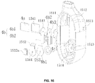
- FIG. 16 is an exploded view illustrating a partial structure of a speaker according to some embodiments of the present disclosure.
- FIG. 17 is a sectional view illustrating a partial structure of a speaker according to some embodiments of the present disclosure.
- FIG. 18 is a partial enlarged view illustrating part C in FIG. 17 according to some embodiments of the present disclosure.
- FIG. 3 illustrates the principles of sound interference according to some embodiments of the present disclosure.
- Two or more sound waves may interfere in the space based on, for example, the frequency and/or amplitude of the waves. Specifically, the amplitudes of the sound waves with the same frequency may be overlaid to generate a strengthened wave or a weakened wave.
- sound source 1 and sound source 2 have the same frequency and locate in different locations in the space. The sound waves generated from these two sound sources may encounter in an arbitrary point A.
- the amplitudes of the two sound waves may be added, generating a strengthened sound wave signal at point A; on the other hand, if the phases of the two sound waves are opposite at point A, their amplitudes may be offset, generating a weakened sound wave signal at point A.
- This disclosure applies above-noted the principles of sound wave interference to a bone conduction speaker and disclose a bone conduction speaker that can reduce sound leakage.
- FIGS. 4 A and 4 B are schematic structures of an exemplary bone conduction speaker.
- the bone conduction speaker may include a housing 10 , a vibration board 21 , and a transducer 22 .
- the transducer 22 may be inside the housing 10 and configured to generate vibrations.
- the housing 10 may have one or more sound guiding holes 30 .
- the sound guiding hole(s) 30 may be configured to guide sound waves inside the housing 10 to the outside of the housing 10 .
- the guided sound waves may form interference with leaked sound waves generated by the vibrations of the housing 10 , so as to reducing the amplitude of the leaked sound.
- the transducer 22 may be configured to convert an electrical signal to mechanical vibrations.
- an audio electrical signal may be transmitted into a voice coil that is placed in a magnet, and the electromagnetic interaction may cause the voice coil to vibrate based on the audio electrical signal.
- the transducer 22 may include piezoelectric ceramics, shape changes of which may cause vibrations in accordance with electrical signals received.
- the vibration board 21 may be connected to the transducer 22 and configured to vibrate along with the transducer 22 .
- the vibration board 21 may stretch out from the opening of the housing 10 , and touch the skin of the user and pass vibrations to auditory nerves through human tissues and bones, which in turn enables the user to hear sound.
- the linking component 23 may reside between the transducer 22 and the housing 10 , configured to fix the vibrating transducer 122 inside the housing.
- the linking component 23 may include one or more separate components, or may be integrated with the transducer 22 or the housing 10 . In some embodiments, the linking component 23 is made of an elastic material.
- the transducer 22 may drive the vibration board 21 to vibrate.
- the transducer 22 which resides inside the housing 10 , may vibrate.
- the vibrations of the transducer 22 may drives the air inside the housing 10 to vibrate, producing a sound wave inside the housing 10 , which can be referred to as “sound wave inside the housing.” Since the vibration board 21 and the transducer 22 are fixed to the housing 10 via the linking component 23 , the vibrations may pass to the housing 10 , causing the housing 10 to vibrate synchronously.
- the vibrations of the housing 10 may generate a leaked sound wave, which spreads outwards as sound leakage.
- the sound wave inside the housing and the leaked sound wave are like the two sound sources in FIG. 3 .
- the sidewall 11 of the housing 10 may have one or more sound guiding holes 30 configured to guide the sound wave inside the housing 10 to the outside.
- the guided sound wave through the sound guiding hole(s) 30 may interfere with the leaked sound wave generated by the vibrations of the housing 10 , and the amplitude of the leaked sound wave may be reduced due to the interference, which may result in a reduced sound leakage. Therefore, the design of this embodiment can solve the sound leakage problem to some extent by making an improvement of setting a sound guiding hole on the housing, and not increasing the volume and weight of the bone conduction speaker.
- one sound guiding hole 30 is set on the upper portion of the sidewall 11 .
- the upper portion of the sidewall 11 refers to the portion of the sidewall 11 starting from the top of the sidewall (contacting with the vibration board 21 ) to about the 1 ⁇ 3 height of the sidewall.
- FIG. 4 C is a schematic structure of the bone conduction speaker illustrated in FIGS. 4 A- 4 B .
- the structure of the bone conduction speaker is further illustrated with mechanics elements illustrated in FIG. 4 C .
- the linking component 23 between the sidewall 11 of the housing 10 and the vibration board 21 may be represented by an elastic element 23 and a damping element in the parallel connection.
- the linking relationship between the vibration board 21 and the transducer 22 may be represented by an elastic element 24 .
- the sound leakage reduction is proportional to ( ⁇ s hole Pds ⁇ s housing P d ds ), (1)
- S hole is the area of the opening of the sound guiding hole 30
- S housing is the area of the housing 10 (e.g., the sidewall 11 and the bottom 12 ) that is not in contact with human face.
- side a refers to the upper surface of the transducer 22 that is close to the vibration board 21
- side b refers to the lower surface of the vibration board 21 that is close to the transducer 22
- side c refers to the inner upper surface of the bottom 12 that is close to the transducer 22
- side e refers to the lower surface of the transducer 22 that is close to the bottom 12 .
- P aR , P bR , P cR and P eR are acoustic resistances of air, which respectively are:
- P aR A ⁇ z a ⁇ r + j ⁇ ⁇ ⁇ ⁇ z a ⁇ r ′ ⁇ + ⁇ , ( 7 )
- P bR A ⁇ z b ⁇ r + j ⁇ ⁇ ⁇ ⁇ z b ⁇ r ′ ⁇ + ⁇
- P cR A ⁇ z c ⁇ r + j ⁇ ⁇ ⁇ ⁇ z c ⁇ r ′ ⁇ + ⁇
- P eR A ⁇ z e ⁇ r + j ⁇ ⁇ ⁇ ⁇ z e ⁇ r ′ ⁇ + ⁇ , ( 10 )
- r is the acoustic resistance per unit length
- r′ is the sound quality per unit length
- z a is the distance between the observation point and side a
- z b is the distance between the observation point and side b
- z c is the distance between the observation point and side c
- z e is the distance between the observation point and side e.
- W a (x, y), W b (x, y), W c (x, y), W e (x, y) and W d (x, y) are the sound source power per unit area of side a, side b, side c, side e and side d, respectively, which can be derived from following formulas (11):
- F b ⁇ F+k 1 cos ⁇ t+ ⁇ s b
- L is the equivalent load on human face when the vibration board acts on the human face
- y is the energy dissipated on elastic element 24
- k 1 and k 2 are the elastic coefficients of elastic element 23 and elastic element 24 respectively
- ⁇ is the fluid viscosity coefficient
- dv/dy is the velocity gradient of fluid
- ⁇ s is the cross-section area of a subject (board)
- A is the amplitude
- ⁇ is the region of the sound field
- ⁇ is a high order minimum (which is generated by the incompletely symmetrical shape of the housing);
- P a , P b , P c and P e are functions of the position, when we set a hole on an arbitrary position in the housing, if the area of the hole is S hole , the sound pressure of the hole is ⁇ s hole Pds.
- the vibration board 21 fits human tissues tightly, the power it gives out is absorbed all by human tissues, so the only side that can push air outside the housing to vibrate is side d, thus forming sound leakage. As described elsewhere, the sound leakage is resulted from the vibrations of the housing 10 .
- the sound pressure generated by the housing 10 may be expressed as ⁇ s housing P d ds.
- ⁇ s hole Pds may be adjusted to reduce the sound leakage. Since ⁇ s hole Pds corresponds to information of phases and amplitudes of one or more holes, which further relates to dimensions of the housing of the bone conduction speaker, the vibration frequency of the transducer, the position, shape, quantity and/or size of the sound guiding holes and whether there is damping inside the holes. Thus, the position, shape, and quantity of sound guiding holes, and/or damping materials may be adjusted to reduce sound leakage.
- the effectiveness of reducing sound leakage is related to the dimensions of the housing of the bone conduction speaker, the vibration frequency of the transducer, the position, shape, quantity and size of the sound guiding hole(s) and whether there is damping inside the sound guiding hole(s). Accordingly, various configurations, depending on specific needs, may be obtained by choosing specific position where the sound guiding hole(s) is located, the shape and/or quantity of the sound guiding hole(s) as well as the damping material.
- FIG. 5 is a diagram illustrating the equal-loudness contour curves according to some embodiments of the present disclose.
- the horizontal coordinate is frequency
- the vertical coordinate is sound pressure level (SPL).
- SPL refers to the change of atmospheric pressure after being disturbed, i.e., a surplus pressure of the atmospheric pressure, which is equivalent to an atmospheric pressure added to a pressure change caused by the disturbance.
- the sound pressure may reflect the amplitude of a sound wave.
- sound pressure levels corresponding to different frequencies are different, while the loudness levels felt by human ears are the same.
- each curve is labeled with a number representing the loudness level of said curve.
- Bone conduction speakers may generate sound relating to different frequency ranges, such as 1000 Hz ⁇ 4000 Hz, or 1000 Hz ⁇ 4000 Hz, or 1000 Hz ⁇ 3500 Hz, or 1000 Hz ⁇ 3000 Hz, or 1500 Hz ⁇ 3000 Hz.
- the sound leakage within the above-mentioned frequency ranges may be the sound leakage aimed to be reduced with a priority.
- FIG. 4 D is a diagram illustrating the effect of reduced sound leakage according to some embodiments of the present disclosure, wherein the test results and calculation results are close in the above range.
- the bone conduction speaker being tested includes a cylindrical housing, which includes a sidewall and a bottom, as described in FIGS. 4 A and 4 B .
- the cylindrical housing is in a cylinder shape having a radius of 22 mm, the sidewall height of 14 mm, and a plurality of sound guiding holes being set on the upper portion of the sidewall of the housing.
- the openings of the sound guiding holes are rectangle.
- the sound guiding holes are arranged evenly on the sidewall.
- the target region where the sound leakage is to be reduced is 50 cm away from the outside of the bottom of the housing.
- the distance of the leaked sound wave spreading to the target region and the distance of the sound wave spreading from the surface of the transducer 20 through the sound guiding holes 30 to the target region have a difference of about 180 degrees in phase. As shown, the leaked sound wave is reduced in the target region dramatically or even be eliminated.
- the effectiveness of reducing sound leakage after setting sound guiding holes is very obvious.
- the bone conduction speaker having sound guiding holes greatly reduce the sound leakage compared to the bone conduction speaker without sound guiding holes.
- the sound leakage is reduced by about 10 dB on average. Specifically, in the frequency range of 1500 Hz ⁇ 3000 Hz, the sound leakage is reduced by over 10 dB. In the frequency range of 2000 Hz ⁇ 2500 Hz, the sound leakage is reduced by over 20 dB compared to the scheme without sound guiding holes.
- a plurality of sound guiding holes may be on the sidewall and/or the bottom of the housing.
- the sound guiding hole may be set on the upper portion and/or lower portion of the sidewall of the housing.
- the quantity of the sound guiding holes set on the sidewall of the housing is no less than two.
- the sound guiding holes may be arranged evenly or unevenly in one or more circles with respect to the center of the bottom.
- the sound guiding holes may be arranged in at least one circle.
- one sound guiding hole may be set on the bottom of the housing.
- the sound guiding hole may be set at the center of the bottom of the housing.
- the quantity of the sound guiding holes can be one or more.
- multiple sound guiding holes may be set symmetrically on the housing. In some embodiments, there are 6-8 circularly arranged sound guiding holes.
- the openings (and cross sections) of sound guiding holes may be circle, ellipse, rectangle, or slit.
- Slit generally means slit along with straight lines, curve lines, or arc lines.
- Different sound guiding holes in one bone conduction speaker may have same or different shapes.
- the sidewall of the housing may not be cylindrical, the sound guiding holes can be arranged asymmetrically as needed.
- Various configurations may be obtained by setting different combinations of the shape, quantity, and position of the sound guiding.
- the leaked sound wave may be generated by a portion of the housing 10 .
- the portion of the housing may be the sidewall 11 of the housing 10 and/or the bottom 12 of the housing 10 .
- the leaked sound wave may be generated by the bottom 12 of the housing 10 .
- the guided sound wave output through the sound guiding hole(s) 30 may interfere with the leaked sound wave generated by the portion of the housing 10 .
- the interference may enhance or reduce a sound pressure level of the guided sound wave and/or leaked sound wave in the target region.
- the portion of the housing 10 that generates the leaked sound wave may be regarded as a first sound source (e.g., the sound source 1 illustrated in FIG. 3 ), and the sound guiding hole(s) 30 or a part thereof may be regarded as a second sound source (e.g., the sound source 2 illustrated in FIG. 3 ).
- the sound guiding hole may be approximately regarded as a point sound source.
- any number or count of sound guiding holes provided on the housing 10 for outputting sound may be approximated as a single point sound source.
- the portion of the housing 10 that generates the leaked sound wave may also be approximately regarded as a point sound source.
- both the first sound source and the second sound source may approximately be regarded as point sound sources (also referred to as two-point sound sources).
- FIG. 4 E is a schematic diagram illustrating exemplary two-point sound sources according to some embodiments of the present disclosure.
- the sound field pressure p generated by a single point sound source may satisfy Equation (13):
- ⁇ denotes an angular frequency
- ⁇ 0 denotes an air density
- r denotes a distance between a target point and the sound source
- Q 0 denotes a volume velocity of the sound source
- k denotes a wave number
- the sound guiding hole(s) for outputting sound as a point sound source may only serve as an explanation of the principle and effect of the present disclosure, and the shape and/or size of the sound guiding hole(s) may not be limited in practical applications.
- the sound guiding hole may also be equivalent to a planar sound source.
- an area of the portion of the housing 10 that generates the leaked sound wave is large (e.g., the portion of the housing 10 is a vibration surface or a sound radiation surface), the portion of the housing 10 may also be equivalent to a planar sound source.
- sounds generated by structures such as sound guiding holes, vibration surfaces, and sound radiation surfaces may be equivalent to point sound sources at the spatial scale discussed in the present disclosure, and may have consistent sound propagation characteristics and the same mathematical description method.
- the acoustic effect achieved by the two-point sound sources may also be implemented by alternative acoustic structures. According to actual situations, the alternative acoustic structures may be modified and/or combined discretionarily, and the same acoustic output effect may be achieved.
- the two-point sound sources may be formed such that the guided sound wave output from the sound guiding hole(s) may interfere with the leaked sound wave generated by the portion of the housing 10 .
- the interference may reduce a sound pressure level of the leaked sound wave in the surrounding environment (e.g., the target region).
- the sound waves output from an acoustic output device e.g., the bone conduction speaker
- the sound waves output from the acoustic output device to the ears of the user may also be referred to as near-field sound since a distance between the bone conduction speaker and the user may be relatively short.
- the sound waves output from the two-point sound sources may have a same frequency or frequency range (e.g., 800 Hz, 1000 Hz, 1500 Hz, 3000 Hz, etc.). In some embodiments, the sound waves output from the two-point sound sources may have a certain phase difference.
- the sound guiding hole includes a damping layer.
- the damping layer may be, for example, a tuning paper, a tuning cotton, a nonwoven fabric, a silk, a cotton, a sponge, or a rubber.
- the damping layer may be configured to adjust the phase of the guided sound wave in the target region.
- the acoustic output device described herein may include a bone conduction speaker or an air conduction speaker.
- a portion of the housing (e.g., the bottom of the housing) of the bone conduction speaker may be treated as one of the two-point sound sources, and at least one sound guiding holes of the bone conduction speaker may be treated as the other one of the two-point sound sources.
- one sound guiding hole of an air conduction speaker may be treated as one of the two-point sound sources, and another sound guiding hole of the air conduction speaker may be treated as the other one of the two-point sound sources.
- the acoustic output device may output different sound effects in the near field (for example, the position of the user's ear) and the far field. For example, if the phases of the point sound sources corresponding to the portion of the housing 10 and the sound guiding hole(s) are opposite, that is, an absolute value of the phase difference between the two-point sound sources is 180 degrees, the far-field leakage may be reduced according to the principle of reversed phase cancellation.
- the interference between the guided sound wave and the leaked sound wave at a specific frequency may relate to a distance between the sound guiding hole(s) and the portion of the housing 10 .
- the distance between the sound guiding hole(s) and the portion of the housing 10 may be large.
- the frequencies of sound waves generated by such two-point sound sources may be in a mid-low frequency range (e.g., 1500-2000 Hz, 1500-2500 Hz, etc.).
- the interference may reduce the sound pressure level of the leaked sound wave in the mid-low frequency range (i.e., the sound leakage is low).
- the low frequency range may refer to frequencies in a range below a first frequency threshold.
- the high frequency range may refer to frequencies in a range exceed a second frequency threshold.
- the first frequency threshold may be lower than the second frequency threshold.
- the mid-low frequency range may refer to frequencies in a range between the first frequency threshold and the second frequency threshold.
- the first frequency threshold may be 1000 Hz
- the second frequency threshold may be 3000 Hz.
- the low frequency range may refer to frequencies in a range below 1000 Hz
- the high frequency range may refer to frequencies in a range above 3000 Hz
- the mid-low frequency range may refer to frequencies in a range of 1000-2000 Hz, 1500-2500 Hz, etc.
- a middle frequency range, a mid-high frequency range may also be determined between the first frequency threshold and the second frequency threshold.
- the mid-low frequency range and the low frequency range may partially overlap.
- the mid-high frequency range and the high frequency range may partially overlap.
- the mid-high frequency range may refer to frequencies in a range above 3000 Hz
- the mid-low frequency range may refer to frequencies in a range of 2800-3500 Hz.
- the low frequency range, the mid-low frequency range, the middle frequency range, the mid-high frequency range, and/or the high frequency range may be set flexibly according to different situations, and are not limited herein.
- the frequencies of the guided sound wave and the leaked sound wave may be set in a low frequency range (e.g., below 800 Hz, below 1200 Hz, etc.).
- the amplitudes of the sound waves generated by the two-point sound sources may be set to be different in the low frequency range.
- the amplitude of the guided sound wave may be smaller than the amplitude of the leaked sound wave.
- the interference may not reduce sound pressure of the near-field sound in the low-frequency range.
- the sound pressure of the near-field sound may be improved in the low-frequency range.
- the volume of the sound heard by the user may be improved.
- the amplitude of the guided sound wave may be adjusted by setting an acoustic resistance structure in the sound guiding hole(s) 30 .
- the material of the acoustic resistance structure disposed in the sound guiding hole 30 may include, but not limited to, plastics (e.g., high-molecular polyethylene, blown nylon, engineering plastics, etc.), cotton, nylon, fiber (e.g., glass fiber, carbon fiber, boron fiber, graphite fiber, graphene fiber, silicon carbide fiber, or aramid fiber), other single or composite materials, other organic and/or inorganic materials, etc.
- the thickness of the acoustic resistance structure may be 0.005 mm, 0.01 mm, 0.02 mm, 0.5 mm, 1 mm, 2 mm, etc.
- the structure of the acoustic resistance structure may be in a shape adapted to the shape of the sound guiding hole.
- the acoustic resistance structure may have a shape of a cylinder, a sphere, a cubic, etc.
- the materials, thickness, and structures of the acoustic resistance structure may be modified and/or combined to obtain a desirable acoustic resistance structure.
- the acoustic resistance structure may be implemented by the damping layer.
- the amplitude of the guided sound wave output from the sound guiding hole may be relatively low (e.g., zero or almost zero).
- the difference between the guided sound wave and the leaked sound wave may be maximized, thus achieving a relatively large sound pressure in the near field.
- the sound leakage of the acoustic output device having sound guiding holes may be almost the same as the sound leakage of the acoustic output device without sound guiding holes in the low frequency range (e.g., as shown in FIG. 4 D ).
- FIG. 6 is a flowchart of an exemplary method of reducing sound leakage of a bone conduction speaker according to some embodiments of the present disclosure.
- a bone conduction speaker including a vibration plate 21 touching human skin and passing vibrations, a transducer 22 , and a housing 10 is provided. At least one sound guiding hole 30 is arranged on the housing 10 .
- the vibration plate 21 is driven by the transducer 22 , causing the vibration 21 to vibrate.
- a leaked sound wave due to the vibrations of the housing is formed, wherein the leaked sound wave transmits in the air.
- a guided sound wave passing through the at least one sound guiding hole 30 from the inside to the outside of the housing 10 . The guided sound wave interferes with the leaked sound wave, reducing the sound leakage of the bone conduction speaker.
- the sound guiding holes 30 are preferably set at different positions of the housing 10 .
- the effectiveness of reducing sound leakage may be determined by the formulas and method as described above, based on which the positions of sound guiding holes may be determined.
- a damping layer is preferably set in a sound guiding hole 30 to adjust the phase and amplitude of the sound wave transmitted through the sound guiding hole 30 .
- different sound guiding holes may generate different sound waves having a same phase to reduce the leaked sound wave having the same wavelength. In some embodiments, different sound guiding holes may generate different sound waves having different phases to reduce the leaked sound waves having different wavelengths.
- different portions of a sound guiding hole 30 may be configured to generate sound waves having a same phase to reduce the leaked sound waves with the same wavelength. In some embodiments, different portions of a sound guiding hole 30 may be configured to generate sound waves having different phases to reduce the leaked sound waves with different wavelengths.
- the sound wave inside the housing may be processed to basically have the same value but opposite phases with the leaked sound wave, so that the sound leakage may be further reduced.
- FIGS. 7 A and 7 B are schematic structures illustrating an exemplary bone conduction speaker according to some embodiments of the present disclosure.
- the bone conduction speaker may include an open housing 10 , a vibration board 21 , and a transducer 22 .
- the housing 10 may cylindrical and have a sidewall and a bottom.
- a plurality of sound guiding holes 30 may be arranged on the lower portion of the sidewall (i.e., from about the 2 ⁇ 3 height of the sidewall to the bottom).
- the quantity of the sound guiding holes 30 may be 8, the openings of the sound guiding holes 30 may be rectangle.
- the sound guiding holes 30 may be arranged evenly or evenly in one or more circles on the sidewall of the housing 10 .
- the transducer 22 is preferably implemented based on the principle of electromagnetic transduction.
- the transducer may include components such as magnetizer, voice coil, and etc., and the components may locate inside the housing and may generate synchronous vibrations with a same frequency.
- FIG. 7 C is a diagram illustrating reduced sound leakage according to some embodiments of the present disclosure.
- the sound leakage is reduced by more than 5 dB
- the frequency range of 2250 Hz ⁇ 2500 Hz the sound leakage is reduced by more than 20 dB.
- the sound guiding hole(s) at the lower portion of the sidewall of the housing 10 may also be approximately regarded as a point sound source.
- the sound guiding hole(s) at the lower portion of the sidewall of the housing 10 and the portion of the housing 10 that generates the leaked sound wave may constitute two-point sound sources.
- the two-point sound sources may be formed such that the guided sound wave output from the sound guiding hole(s) at the lower portion of the sidewall of the housing 10 may interfere with the leaked sound wave generated by the portion of the housing 10 .
- the interference may reduce a sound pressure level of the leaked sound wave in the surrounding environment (e.g., the target region) at a specific frequency or frequency range.
- the sound waves output from the two-point sound sources may have a same frequency or frequency range (e.g., 1000 Hz, 2500 Hz, 3000 Hz, etc.).
- the sound waves output from the first two-point sound sources may have a certain phase difference.
- the interference between the sound waves generated by the first two-point sound sources may reduce a sound pressure level of the leaked sound wave in the target region.
- the acoustic output device may output different sound effects in the near field (for example, the position of the user's ear) and the far field. For example, if the phases of the first two-point sound sources are opposite, that is, an absolute value of the phase difference between the first two-point sound sources is 180 degrees, the far-field leakage may be reduced.
- the interference between the guided sound wave and the leaked sound wave may relate to frequencies of the guided sound wave and the leaked sound wave and/or a distance between the sound guiding hole(s) and the portion of the housing 10 .
- the distance between the sound guiding hole(s) and the portion of the housing 10 may be small.
- the frequencies of sound waves generated by such two-point sound sources may be in a high frequency range (e.g., above 3000 Hz, above 3500 Hz, etc.).
- the interference may reduce the sound pressure level of the leaked sound wave in the high frequency range.
- FIGS. 8 A and 8 B are schematic structures illustrating an exemplary bone conduction speaker according to some embodiments of the present disclosure.
- the bone conduction speaker may include an open housing 10 , a vibration board 21 , and a transducer 22 .
- the housing 10 is cylindrical and have a sidewall and a bottom.
- the sound guiding holes 30 may be arranged on the central portion of the sidewall of the housing (i.e., from about the 1 ⁇ 3 height of the sidewall to the 2 ⁇ 3 height of the sidewall).
- the quantity of the sound guiding holes 30 may be 8, and the openings (and cross sections) of the sound guiding hole 30 may be rectangle.
- the sound guiding holes 30 may be arranged evenly or unevenly in one or more circles on the sidewall of the housing 10 .
- the transducer 21 may be implemented preferably based on the principle of electromagnetic transduction.
- the transducer 21 may include components such as magnetizer, voice coil, etc., which may be placed inside the housing and may generate synchronous vibrations with the same frequency.
- FIG. 8 C is a diagram illustrating reduced sound leakage.
- the effectiveness of reducing sound leakage is great.
- the sound leakage is reduced by more than 10 dB; in the frequency range of 2200 Hz ⁇ 2500 Hz, the sound leakage is reduced by more than 20 dB.
- FIGS. 9 A and 9 B are schematic structures of an exemplary bone conduction speaker according to some embodiments of the present disclosure.
- the bone conduction speaker may include an open housing 10 , a vibration board 21 and a transducer 22 .
- the housing 10 is cylindrical, with a sidewall and a bottom.
- One or more perforative sound guiding holes 30 may be along the circumference of the bottom.
- the shape of one or more of the sound guiding holes 30 may be rectangle.
- the transducer 21 may be implemented preferably based on the principle of electromagnetic transduction.
- the transducer 21 may include components such as magnetizer, voice coil, etc., which may be placed inside the housing and may generate synchronous vibration with the same frequency.
- FIG. 9 C is a diagram illustrating the effect of reduced sound leakage.
- the effectiveness of reducing sound leakage is outstanding.
- the sound leakage is reduced by more than 10 dB; in the frequency range of 2200 Hz ⁇ 2400 Hz, the sound leakage is reduced by more than 20 dB.
- FIGS. 10 A and 10 B are schematic structures of an exemplary bone conduction speaker according to some embodiments of the present disclosure.
- the bone conduction speaker may include an open housing 10 , a vibration board 21 and a transducer 22 .
- One or more perforative sound guiding holes 30 may be arranged on both upper and lower portions of the sidewall of the housing 10 .
- the sound guiding holes 30 may be arranged evenly or unevenly in one or more circles on the upper and lower portions of the sidewall of the housing 10 .
- the quantity of sound guiding holes 30 in every circle may be 8, and the upper portion sound guiding holes and the lower portion sound guiding holes may be symmetrical about the central cross section of the housing 10 .
- the shape of the sound guiding hole 30 may be circle.
- the shape of the sound guiding holes on the upper portion and the shape of the sound guiding holes on the lower portion may be different;
- One or more damping layers may be arranged in the sound guiding holes to reduce leaked sound waves of the same wave length (or frequency), or to reduce leaked sound waves of different wave lengths.
- FIG. 10 C is a diagram illustrating the effect of reducing sound leakage according to some embodiments of the present disclosure.
- the effectiveness of reducing sound leakage is outstanding.
- the sound leakage is reduced by more than 15 dB; in the frequency range of 2000 Hz ⁇ 2500 Hz, where the effectiveness of reducing sound leakage is most outstanding, the sound leakage is reduced by more than 20 dB.
- this scheme has a relatively balanced effect of reduced sound leakage on various frequency range, and this effect is better than the effect of schemes where the height of the holes are fixed, such as schemes of embodiment three, embodiment four, embodiment five, and so on.
- the sound guiding hole(s) at the upper portion of the sidewall of the housing 10 may be approximately regarded as a point sound source.
- the first hole(s) and the portion of the housing 10 that generates the leaked sound wave may constitute two-point sound sources (also referred to as first two-point sound sources).
- the guided sound wave generated by the first hole(s) (also referred to as first guided sound wave) may interfere with the leaked sound wave or a portion thereof generated by the portion of the housing 10 in a first region.
- the sound waves output from the first two-point sound sources may have a same frequency (e.g., a first frequency).
- the sound waves output from the first two-point sound sources may have a certain phase difference.
- the interference between the sound waves generated by the first two-point sound sources may reduce a sound pressure level of the leaked sound wave in the target region.
- the acoustic output device may output different sound effects in the near field (for example, the position of the user's ear) and the far field. For example, if the phases of the first two-point sound sources are opposite, that is, an absolute value of the phase difference between the first two-point sound sources is 180 degrees, the far-field leakage may be reduced according to the principle of reversed phase cancellation.
- the sound guiding hole(s) at the lower portion of the sidewall of the housing 10 may also be approximately regarded as another point sound source.
- the second hole(s) and the portion of the housing 10 that generates the leaked sound wave may also constitute two-point sound sources (also referred to as second two-point sound sources).
- the guided sound wave generated by the second hole(s) (also referred to as second guided sound wave) may interfere with the leaked sound wave or a portion thereof generated by the portion of the housing 10 in a second region.
- the second region may be the same as or different from the first region.
- the sound waves output from the second two-point sound sources may have a same frequency (e.g., a second frequency).
- the first frequency and the second frequency may be in certain frequency ranges.
- the frequency of the guided sound wave output from the sound guiding hole(s) may be adjustable.
- the frequency of the first guided sound wave and/or the second guided sound wave may be adjusted by one or more acoustic routes.
- the acoustic routes may be coupled to the first hole(s) and/or the second hole(s).
- the first guided sound wave and/or the second guided sound wave may be propagated along the acoustic route having a specific frequency selection characteristic. That is, the first guided sound wave and the second guided sound wave may be transmitted to their corresponding sound guiding holes via different acoustic routes.
- the first guided sound wave and/or the second guided sound wave may be propagated along an acoustic route with a low-pass characteristic to a corresponding sound guiding hole to output guided sound wave of a low frequency.
- the high frequency component of the sound wave may be absorbed or attenuated by the acoustic route with the low-pass characteristic.
- the first guided sound wave and/or the second guided sound wave may be propagated along an acoustic route with a high-pass characteristic to the corresponding sound guiding hole to output guided sound wave of a high frequency.
- the low frequency component of the sound wave may be absorbed or attenuated by the acoustic route with the high-pass characteristic.
- FIG. 10 D is a schematic diagram illustrating an acoustic route according to some embodiments of the present disclosure.
- FIG. 10 E is a schematic diagram illustrating another acoustic route according to some embodiments of the present disclosure.
- FIG. 10 F is a schematic diagram illustrating a further acoustic route according to some embodiments of the present disclosure.
- structures such as a sound tube, a sound cavity, a sound resistance, etc., may be set in the acoustic route for adjusting frequencies for the sound waves (e.g., by filtering certain frequencies).
- FIGS. 10 D- 10 F may be provided as examples of the acoustic routes, and not intended be limiting.
- the acoustic route may include one or more lumen structures.
- the one or more lumen structures may be connected in series.
- An acoustic resistance material may be provided in each of at least one of the one or more lumen structures to adjust acoustic impedance of the entire structure to achieve a desirable sound filtering effect.
- the acoustic impedance may be in a range of 5MKS Rayleigh to 500MKS Rayleigh.
- a high-pass sound filtering, a low-pass sound filtering, and/or a band-pass filtering effect of the acoustic route may be achieved by adjusting a size of each of at least one of the one or more lumen structures and/or a type of acoustic resistance material in each of at least one of the one or more lumen structures.
- the acoustic resistance materials may include, but not limited to, plastic, textile, metal, permeable material, woven material, screen material or mesh material, porous material, particulate material, polymer material, or the like, or any combination thereof.
- the acoustic route may include one or more resonance cavities.
- the one or more resonance cavities may be, for example, Helmholtz cavity.
- a high-pass sound filtering, a low-pass sound filtering, and/or a band-pass filtering effect of the acoustic route may be achieved by adjusting a size of each of at least one of the one or more resonance cavities and/or a type of acoustic resistance material in each of at least one of the one or more resonance cavities.
- the acoustic route may include a combination of one or more lumen structures and one or more resonance cavities.
- a high-pass sound filtering, a low-pass sound filtering, and/or a band-pass filtering effect of the acoustic route may be achieved by adjusting a size of each of at least one of the one or more lumen structures and one or more resonance cavities and/or a type of acoustic resistance material in each of at least one of the one or more lumen structures and one or more resonance cavities.
- the structures exemplified above may be for illustration purposes, various acoustic structures may also be provided, such as a tuning net, tuning cotton, etc.
- the interference between the leaked sound wave and the guided sound wave may relate to frequencies of the guided sound wave and the leaked sound wave and/or a distance between the sound guiding hole(s) and the portion of the housing 10 .
- the portion of the housing that generates the leaked sound wave may be the bottom of the housing 10 .
- the first hole(s) may have a larger distance to the portion of the housing 10 than the second hole(s).
- the frequency of the first guided sound wave output from the first hole(s) e.g., the first frequency
- the frequency of second guided sound wave output from second hole(s) e.g., the second frequency
- the first frequency and second frequency may associate with the distance between the at least one sound guiding hole and the portion of the housing 10 that generates the leaked sound wave.
- the first frequency may be set in a low frequency range.
- the second frequency may be set in a high frequency range. The low frequency range and the high frequency range may or may not overlap.
- the frequency of the leaked sound wave generated by the portion of the housing 10 may be in a wide frequency range.
- the wide frequency range may include, for example, the low frequency range and the high frequency range or a portion of the low frequency range and the high frequency range.
- the leaked sound wave may include a first frequency in the low frequency range and a second frequency in the high frequency range.
- the leaked sound wave of the first frequency and the leaked sound wave of the second frequency may be generated by different portions of the housing 10 .
- the leaked sound wave of the first frequency may be generated by the sidewall of the housing 10
- the leaked sound wave of the second frequency may be generated by the bottom of the housing 10 .
- the leaked sound wave of the first frequency may be generated by the bottom of the housing 10
- the leaked sound wave of the second frequency may be generated by the sidewall of the housing 10
- the frequency of the leaked sound wave generated by the portion of the housing 10 may relate to parameters including the mass, the damping, the stiffness, etc., of the different portion of the housing 10 , the frequency of the transducer 22 , etc.
- the characteristics (amplitude, frequency, and phase) of the first two-point sound sources and the second two-point sound sources may be adjusted via various parameters of the acoustic output device (e.g., electrical parameters of the transducer 22 , the mass, stiffness, size, structure, material, etc., of the portion of the housing 10 , the position, shape, structure, and/or number (or count) of the sound guiding hole(s) so as to form a sound field with a particular spatial distribution.
- a frequency of the first guided sound wave is smaller than a frequency of the second guided sound wave.
- a combination of the first two-point sound sources and the second two-point sound sources may improve sound effects both in the near field and the far field.
- the sound leakage in both the low frequency range and the high frequency range may be properly suppressed.
- the closer distance between the second two-point sound sources may be more suitable for suppressing the sound leakage in the far field, and the relative longer distance between the first two-point sound sources may be more suitable for reducing the sound leakage in the near field.
- the amplitudes of the sound waves generated by the first two-point sound sources may be set to be different in the low frequency range.
- the amplitude of the guided sound wave may be smaller than the amplitude of the leaked sound wave. In this case, the sound pressure level of the near-field sound may be improved. The volume of the sound heard by the user may be increased.
- FIGS. 11 A and 11 B are schematic structures illustrating a bone conduction speaker according to some embodiments of the present disclosure.
- the bone conduction speaker may include an open housing 10 , a vibration board 21 and a transducer 22 .
- One or more perforative sound guiding holes 30 may be set on upper and lower portions of the sidewall of the housing 10 and on the bottom of the housing 10 .
- the sound guiding holes 30 on the sidewall are arranged evenly or unevenly in one or more circles on the upper and lower portions of the sidewall of the housing 10 .
- the quantity of sound guiding holes 30 in every circle may be 8, and the upper portion sound guiding holes and the lower portion sound guiding holes may be symmetrical about the central cross section of the housing 10 .
- the shape of the sound guiding hole 30 may be rectangular. There may be four sound guiding holds 30 on the bottom of the housing 10 .
- the four sound guiding holes 30 may be linear-shaped along arcs, and may be arranged evenly or unevenly in one or more circles with respect to the center of the bottom.
- the sound guiding holes 30 may include a circular perforative hole on the center of the bottom.
- FIG. 11 C is a diagram illustrating the effect of reducing sound leakage of the embodiment.
- the effectiveness of reducing sound leakage is outstanding.
- the sound leakage is reduced by more than 10 dB; in the frequency range of 2000 Hz ⁇ 2700 Hz, the sound leakage is reduced by more than 20 dB.
- this scheme has a relatively balanced effect of reduced sound leakage within various frequency range, and this effect is better than the effect of schemes where the height of the holes are fixed, such as schemes of embodiment three, embodiment four, embodiment five, and etc.
- this scheme has a better effect of reduced sound leakage than embodiment six.
- FIGS. 12 A and 12 B are schematic structures illustrating a bone conduction speaker according to some embodiments of the present disclosure.
- the bone conduction speaker may include an open housing 10 , a vibration board 21 and a transducer 22 .
- a perforative sound guiding hole 30 may be set on the upper portion of the sidewall of the housing 10 .
- One or more sound guiding holes may be arranged evenly or unevenly in one or more circles on the upper portion of the sidewall of the housing 10 .
- FIGS. 13 A and 13 B are schematic structures illustrating a bone conduction speaker according to some embodiments of the present disclosure.
- the bone conduction speaker may include an open housing 10 , a vibration board 21 and a transducer 22 .
- the sound guiding holes 30 may be arranged on the upper, central and lower portions of the sidewall 11 .
- the sound guiding holes 30 are arranged evenly or unevenly in one or more circles. Different circles are formed by the sound guiding holes 30 , one of which is set along the circumference of the bottom 12 of the housing 10 .
- the size of the sound guiding holes 30 are the same.
- the effect of this scheme may cause a relatively balanced effect of reducing sound leakage in various frequency ranges compared to the schemes where the position of the holes are fixed.
- the effect of this design on reducing sound leakage is relatively better than that of other designs where the heights of the holes are fixed, such as embodiment three, embodiment four, embodiment five, etc.
- the sound guiding holes 30 in the above embodiments may be perforative holes without shields.
- a damping layer may locate at the opening of a sound guiding hole 30 to adjust the phase and/or the amplitude of the sound wave.
- the damping layer may be made of materials which can damp sound waves, such as tuning paper, tuning cotton, nonwoven fabric, silk, cotton, sponge or rubber.
- the damping layer may be attached on the inner wall of the sound guiding hole 30 , or may shield the sound guiding hole 30 from outside.
- the damping layers corresponding to different sound guiding holes 30 may be arranged to adjust the sound waves from different sound guiding holes to generate a same phase.
- the adjusted sound waves may be used to reduce leaked sound wave having the same wavelength.
- different sound guiding holes 30 may be arranged to generate different phases to reduce leaked sound wave having different wavelengths (i.e., leaked sound waves with specific wavelengths).
- different portions of a same sound guiding hole can be configured to generate a same phase to reduce leaked sound waves on the same wavelength (e.g., using a pre-set damping layer with the shape of stairs or steps). In some embodiments, different portions of a same sound guiding hole can be configured to generate different phases to reduce leaked sound waves on different wavelengths.
- the housing of the bone conduction speakers is closed, so the sound source inside the housing is sealed inside the housing.
- there can be holes in proper positions of the housing making the sound waves inside the housing and the leaked sound waves having substantially same amplitude and substantially opposite phases in the space, so that the sound waves can interfere with each other and the sound leakage of the bone conduction speaker is reduced.
- the volume and weight of the speaker do not increase, the reliability of the product is not comprised, and the cost is barely increased.
- the designs disclosed herein are easy to implement, reliable, and effective in reducing sound leakage.
- an environmental sound collection and processing function may be added to a speaker as described elsewhere in the present disclosure, e.g., to enable the speaker to implement the function of a hearing aid, or to collect the voice of the user/wearer to enable voice communication with others.
- an electronic component including a microphone may be added to the speaker.
- the microphone may collect environmental sounds of a user/wearer, process the sounds using an algorithm and transmit the processed sound (or generated electrical signal) to the user/wearer of the speaker. That is, the speaker may be modified to include the function of collecting the environmental sounds, and after a signal processing, the sound may be transmitted to the user/wearer via the speaker, thereby implementing the function of the hearing aid.
- the algorithm mentioned herein may include noise cancellation, automatic gain control, acoustic feedback suppression, wide dynamic range compression, active environment recognition, active noise reduction, directional processing, tinnitus processing, multi-channel wide dynamic range compression, active howling suppression, volume control, or the like, or any combination thereof.
- FIG. 14 is a sectional view illustrating an electronic component according to the present disclosure.
- the electronic component may be a portion of a speaker described elsewhere in the present disclosure.
- the electronic component may include a first microphone element 1412 , a bracket 141 , a circuit component (e.g., including a first circuit board 142 - 1 , a second circuit board 142 - 2 ), a cover layer 143 , a chamber 145 , etc.
- the bracket 141 may be used to physically connect to an accommodation body of the speaker.
- the cover layer 143 may integrally form on the surface of the bracket 141 by injection molding to provide a seal for the chamber 145 after the bracket 141 is connected to the accommodation body.
- the first microphone element 1412 may be disposed on the first circuit board 142 - 1 of the circuit component to be accommodated inside the chamber 145 .
- the first microphone element 1412 may be used to receive a sound signal from the outside of the electronic component, and convert the sound signal into an electrical signal for analysis and processing.
- the first microphone element 1412 may also be referred to as a microphone 1412 for brevity.
- the bracket 141 may be disposed with a microphone hole corresponding to the first microphone element 1412 .
- the cover layer 143 may be disposed with a first sound guiding hole 1223 corresponding to the microphone hole.
- a first sound blocking member 1224 may be disposed at a position corresponding to the microphone hole.
- the first sound blocking member 1224 may extend towards the inside of the chamber 145 via the microphone hole and define a sound guiding channel 12241 .
- One end of the sound guiding channel 12241 may be in communication with the first sound guiding hole 1223 of the cover layer 143 .
- the first microphone element 1412 may be inserted into the sound guiding channel 12241 from another end of the sound guiding channel 12241 .
- the electronic component may also include a switch in the embodiment.
- the circuit component may be disposed with the switch.
- the switch may be disposed on an outer side of the first circuit board 142 - 1 towards an opening of the chamber 145 .
- the bracket 141 may be disposed with a switch hole corresponding to the switch.
- the cover layer 143 may further cover the switch hole.
- the switch hole and the microphone hole may be disposed on the bracket 141 at intervals.
- the first sound guiding hole 1223 may be disposed through the cover layer 143 and correspond to the position of the first microphone element 1412 .
- the first sound guiding hole 1223 may correspond to the microphone hole of the bracket 141 , and further communicate the first microphone element 1412 with the outside of the electronic component. Therefore, a sound from the outside of the electronic component may be received by the first microphone element 1412 via the first sound guiding hole 1223 and the microphone hole.
- the shape of the first sound guiding hole 1223 may be any shape as long as the sound from the outside of the electronic component is able to be received by the electronic component.
- the first sound guiding hole 1223 may be a circular hole having a relatively small size, and disposed in a region of the cover layer 143 corresponding to the microphone hole. The first sound guiding hole 1223 with the small size may limit the communication between the first microphone element 1412 or the like in the electronic component and the outside, thereby improving the sealing of the electronic component.
- the first sound blocking member 1224 may extend to the periphery of the first microphone element 1412 from the cover layer 143 , through the periphery of the first sound guiding hole 1223 , the microphone hole and the inside of the chamber 145 to form the sound guiding channel 12241 from the first sound guiding hole 1223 to the first microphone element 1412 . Therefore, the sound signal of the electronic component entering the sound guiding hole may directly reach the first microphone element 1412 through the sound guiding channel 12241 .
- a shape of the sound guiding channel 12241 in a section perpendicular to the length direction may be the same as or different from the shape of the microphone hole or the first microphone element 1412 .
- the sectional shapes of the microphone hole and the first microphone element 1412 in a direction perpendicular to the bracket 141 towards the chamber 145 may be square.
- the size of the microphone hole may be slightly larger than the outer size of the sound guiding channel 12241 .
- the inner size of the sound guiding channel 12241 may not be less than the outer size of the first microphone element 1412 . Therefore, the sound guiding channel 12241 may pass through the first sound guiding hole 1223 to reach the first microphone element 1412 and be wrapped around the periphery of the first microphone element 1412 .
- the cover layer 143 of the electronic component may be disposed with the first sound guiding hole 1223 and the sound guiding channel 12241 passing from the periphery of the first sound guiding hole 1223 through the microphone hole to reach the first microphone element 1412 and wrapped around the periphery of the first microphone element 1412 .
- the sound guiding channel 12241 may be disposed so that the sound signal entering through the first sound guiding hole 1223 may reach the first microphone element 1412 via the first sound guiding hole 1223 and be received by the first microphone element 1412 . Therefore, the leakage of the sound signal in the transmission process may be reduced, thereby improving the efficiency of receiving the electronic signal by the electronic component.
- the electronic component may also include a waterproof mesh cloth 146 disposed inside the sound guiding channel 12241 .
- the waterproof mesh cloth 146 may be held against the side of the cover layer 143 towards the microphone element by the first microphone element 1412 and cover the first sound guiding hole 1223 .
- the bracket 141 may protrude at a position of the bracket 141 close to the first microphone element 1412 in the sound guiding channel 12241 to form a convex surface opposite to the first microphone element 1412 . Therefore, the waterproof mesh cloth 146 may be sandwiched between the first microphone element 1412 and the convex surface, or directly adhered to the periphery of the first microphone element 1412 , and the specific setting manner may not be limited herein.
- the waterproof mesh cloth 146 in the embodiment may also have a function of sound transmission, etc., to avoid adversely affecting the sound receiving effect of a sound receiving region 13121 of the first microphone element 1412 .
- the cover layer 143 may be arranged in a stripe shape.
- a main axis of the first sound guiding hole 1223 and a main axis of the sound receiving region 13121 of the first microphone element 1412 may be spaced from each other in the width direction of the cover layer 143 .
- the main axis of the sound receiving region 13121 of the first microphone element 1412 may refer to a main axis of the sound receiving region 13121 of the first microphone element 1412 in the width direction of the cover layer 143 , such as an axis n in FIG. 14 .
- the main axis of the first sound guiding hole 1223 may be an axis m in FIG. 14 .
- the first microphone element 1412 may be disposed at a first position of the first circuit board 142 - 1 .
- the first sound guiding hole 1223 may be disposed at a second position of the cover layer 143 due to the aesthetic and convenient requirements.
- the first position and the second position may not correspond in the width direction of the cover layer 143 . Therefore, the main axis of the first sound guiding hole 1223 and the main axis of the sound receiving region 13121 of the first microphone element 1412 may be spaced from each other in the width direction of the cover layer 143 . Therefore, the sound input via the first sound guiding hole 1223 may not reach the sound receiving region 13121 of the first microphone element 1412 along a straight line.
- the sound guiding channel 12241 may be disposed with a curved shape.
- the main axis of the first sound guiding hole 1223 may be disposed in the middle of the cover layer 143 in the width direction of the cover layer 143 .
- the cover layer 143 may be a portion of the outer housing of the electronic device.
- the first sound guiding hole 1223 may be disposed in the middle in the width direction of the cover layer 143 . Therefore, the first sound guiding hole 1223 may look more symmetrical and meet the visual requirements of people.
- the corresponding sound guiding channel 12241 may be disposed with a stepped shape in a section. Therefore, the sound signal introduced by the first sound guiding hole 1223 may be transmitted to the first microphone element 1412 through the stepped sound guiding channel 12241 and received by the first microphone element 1412 .
- FIG. 15 is a partial structural diagram illustrating a speaker according to an embodiment of the present disclosure.
- FIG. 16 is an exploded diagram illustrating a partial structure of a speaker according to an embodiment of the present disclosure.
- FIG. 17 is a sectional view illustrating a partial structure of a speaker according to an embodiment of the present disclosure.
- the speaker described herein may be similar to a speaker described elsewhere in the present disclosure. It should be noted that, without departing from the spirit and scope of the present disclosure, the contents described below may be applied to an air conduction speaker and a bone conduction speaker.
- the speaker may include one or more microphones.
- the number (or count) of the microphones may include two, i.e., a first microphone 1532 a and a second microphone 1532 b .
- the first microphone 1532 a and the second microphone 1532 b may both be MEMS (micro-electromechanical system) microphones which may have a small working current, relatively stable performance, and high voice quality.
- the two microphones may be disposed at different positions of a flexible circuit board 154 according to actual requirements.
- the flexible circuit board 154 may be disposed in the speaker.
- the flexible circuit board 154 may include a main circuit board 1541 , and a branch circuit board 1542 and a branch circuit board 1543 connected to the main circuit board 1541 .
- the branch circuit board 1542 may extend in the same direction as the main circuit board 1541 .
- the first microphone 1532 a may be disposed on one end of the branch circuit board 1542 away from the main circuit board 1541 .
- the branch circuit board 1543 may extend perpendicular to the main circuit board 1541 .
- the second microphone 1532 b may be disposed on one end of the branch circuit board 1543 away from the main circuit board 1541 .
- a plurality of pads 155 may be disposed on the end of the main circuit board 1541 away from the branch circuit board 1542 and the branch circuit board 1543 .
- the one or more microphones may be connected to the main circuit board 1541 by one or more wires (e.g., a wire 157 , a wire 159 , etc.).
- a core housing (also referred to as a housing for brevity) may include a peripheral side wall 1511 and a bottom end wall 1512 connected to one end surface of the peripheral side wall 1511 to form an accommodation space with an open end.
- an earphone core 1642 may be placed in the accommodation space through the open end.
- the first microphone 1532 a may be fixed on the bottom end wall 1512 .
- the second microphone 1532 b may be fixed on the peripheral side wall 1511 .
- the branch circuit board 1542 and/or the branch circuit board 1543 may be appropriately bent to suit a position of a sound inlet corresponding to the microphone at the core housing.
- the flexible circuit board 154 may be disposed in the core housing in a manner that the main circuit board 1541 is parallel to the bottom end wall 1512 . Therefore, the first microphone 1532 a may correspond to the bottom end wall 1512 without bending the main circuit board 1541 . Since the second microphone 1532 b may be fixed to the peripheral side wall 1511 of the core housing, it may be necessary to bend the main circuit board 1541 .
- the branch circuit board 1543 may be bent at one end away from the main circuit board 1541 so that a board surface of the branch circuit board 1543 may be perpendicular to a board surface of the main circuit board 1541 and the branch circuit board 1542 .
- the second microphone 1532 b may be fixed at the peripheral side wall 1511 of the core housing in a direction facing away from the main circuit board 1541 and the branch circuit board 1542 .
- a pad 155 , a pad 156 (not shown in figures), the first microphone 1532 a , and the second microphone 1532 b may be disposed on the same side of the flexible circuit board 154 .
- the pad 156 may be disposed adjacent to the second microphone 1532 b.
- the pad 156 may be specifically disposed at one end of the branch circuit board 1543 away from the main circuit board 1541 , and have the same orientation as the second microphone 1532 b and disposed at intervals. Therefore, the pad 156 may be perpendicular to the orientation of the pad 155 as the branch circuit board 1543 is bent. It should be noted that the board surface of the branch circuit board 1543 may not be perpendicular to the board surface of the main circuit board 1541 after the branch circuit board 1543 is bent, which may be determined according to the arrangement between the peripheral side wall 1511 and the bottom end wall 1512 .
- another side of the flexible circuit board 154 may be disposed with a rigid support plate 4 a and a microphone rigid support plate 4 b for supporting the pad 155 .
- the microphone rigid support plate 4 b may include a rigid support plate 4 b 1 for supporting the first microphone 1532 a and a rigid support plate 4 b 2 for supporting the pad 156 and the second microphone 1532 b together.
- the rigid support plate 4 a , the rigid support plate 4 b 1 , and the rigid support plate 4 b 2 may be mainly used to support the corresponding pads and the microphone, and thus may need to have strengths.
- the materials of the three may be the same or different.
- the specific material may be polyimide (PI), or other materials that may provide the strengths, such as polycarbonate, polyvinyl chloride, etc.
- the thicknesses of the three rigid support plates may be set according to the strengths of the rigid support plates and actual strengths required by the pad 155 , the pad 156 , the first microphone 1532 a , and the second microphone 1532 b , and be not specifically limited herein.
- the first microphone 1532 a and the second microphone 1532 b may correspond to two microphone components 4 c , respectively.
- the structures of the two microphone components 4 c may be the same.
- a sound inlet 1513 may be disposed on the core housing.
- the speaker may be further disposed with an annular blocking wall 1514 integrally formed on the inner surface of the core housing, and disposed at the periphery of the sound inlet 1513 , thereby defining an accommodation space 1515 connected to the sound inlet 1513 .
- the microphone component 4 c may further include a waterproof membrane component 4 c 1 .
- the waterproof membrane component 4 c 1 may be disposed inside the accommodation space 1515 and cover the sound inlet 1513 .
- the microphone rigid support plate 4 b may be disposed inside the accommodation space 1515 and located at one side of the waterproof membrane component 4 c 1 away from the sound inlet 1513 . Therefore, the waterproof membrane component 4 c 1 may be pressed on the inner surface of the core housing.
- the microphone rigid support plate 4 b may be disposed with a sound inlet 4 b 3 corresponding to the sound inlet 1513 .
- the microphone may be disposed on one side of the microphone rigid support plate 4 b away from the waterproof membrane component 4 c 1 and cover the sound inlet 4 b 3 .
- the waterproof membrane component 4 c 1 may have functions of waterproofing and transmitting the sound, and closely attached to the inner surface of the core housing to prevent the liquid outside the core housing entering the core housing via the sound inlet 1513 and affect the performance of the microphone.
- the axial directions of the sound inlet 4 b 3 and the sound inlet 1513 may overlap, or intersect at an angle according to actual requirements of the microphone, etc.
- the microphone rigid support plate 4 b may be disposed between the waterproof membrane component 4 c 1 and the microphone.
- the waterproof membrane component 4 c 1 may be pressed so that the waterproof membrane component 4 c 1 may be closely attached to the inner surface of the core housing.
- the microphone rigid support plate 4 b may have a strength, thereby playing the role of supporting the microphone.
- the material of the microphone rigid support plate 4 b may be polyimide (PI), or other materials capable of providing the strength, such as polycarbonate, polyvinyl chloride, or the like.
- the thickness of the microphone rigid support plate 4 b may be set according to the strength of the microphone rigid support plate 4 b and the actual strength required by the microphone, and be not specifically limited herein.
- FIG. 18 is a partially enlarged view illustrating part C in FIG. 17 according to some embodiments of the present disclosure.
- the waterproof membrane component 4 c 1 may include a waterproof membrane body 4 c 11 and an annular rubber gasket 4 c 12 .
- the annular rubber gasket 4 c 12 may be disposed at one side of the waterproof membrane body 4 c 11 towards the microphone rigid support plate 4 b , and further disposed on the periphery of the sound inlet 1513 and the sound inlet 4 b 3 .
- the microphone rigid support plate 4 b may be pressed against the annular rubber gasket 4 c 12 . Therefore, the waterproof membrane component 4 c 1 and the microphone rigid support plate 4 b may be adhered and fixed together.
- the annular rubber gasket 4 c 12 may be arranged to form a sealed chamber communicating with the microphone and only through the sound inlet 4 b 3 between the waterproof membrane body 4 c 11 and the rigid support plate. That is, there may be no gap in a connection between the waterproof membrane component 4 c 1 and the microphone rigid support plate 4 b . Therefore, a space around the annular rubber gasket 4 c 12 between the waterproof membrane body 4 c 11 and the microphone rigid support plate 4 b may be isolated from the sound inlet 4 b 3 .
- the waterproof membrane body 4 c 11 may be a waterproof and sound-transmitting membrane and be equivalent to a human eardrum.
- the waterproof membrane body 4 c 11 may vibrate, thereby changing an air pressure in the sealed chamber and generating a sound in the microphone.
- the waterproof membrane body 4 c 11 may change the air pressure in the sealed chamber during the vibration, the air pressure may need to be controlled within an appropriate range. If it is too large or too small, it may affect the sound quality.
- a distance between the waterproof membrane body 4 c 11 and the rigid support plate may be 0.1-0.2 mm, specifically 0.1 mm, 0.15 mm, 0.2 mm, etc. Therefore, the change of the air pressure in the sealed chamber during the vibration of the waterproof film body 4 c 11 may be within the appropriate range, thereby improving the sound quality.
- the waterproof membrane component 4 c 1 may further include an annular rubber gasket 4 c 13 disposed on the waterproof membrane body 4 c 11 towards the inner surface side of the core housing and overlapping the annular rubber gasket 4 c 12 .
- the waterproof membrane component 4 c 1 may be closely attached to the inner surface of the core housing at the periphery of the sound inlet 1513 , thereby reducing the loss of the sound entered via the sound inlet 1513 , and improving a conversion rate of converting the sound into the vibration of the waterproof membrane body 4 c 11 .
- the annular rubber gasket 4 c 12 and the annular rubber gasket 4 c 13 may be a double-sided tape, a sealant, etc., respectively.
- the sealant may be further coated on the peripheries of the annular blocking wall 1514 and the microphone to further improve the sealing, thereby improving the conversion rate of the sound and the sound quality.
- the flexible circuit board 154 may be disposed between the rigid support plate and the microphone.
- a sound inlet 1544 may be disposed at a position corresponding to the sound inlet 4 b 3 of the microphone rigid support plate 4 b . Therefore, the vibration of the waterproof membrane body 4 c 11 generated by the external sound may pass through the sound inlet 1544 , thereby further affecting the microphone.
- the flexible circuit board 154 may further extend away from the microphone, so as to be connected to other functional components or wires to implement corresponding functions.
- the microphone rigid support plate 4 b may also extend out a distance with the flexible circuit board in a direction away from the microphone.
- the annular blocking wall 1514 may be disposed with a gap matching the shape of the flexible circuit board to allow the flexible circuit board to extend from the accommodation space 1515 .
- the gap may be further filled with the sealant to further improve the sealing.
- the above description of the microphone waterproof is only a specific example, and should not be considered as the only feasible implementation.
- the count of the sound inlets 1513 may be set as one or multiple. All such modifications are within the protection scope of the present disclosure.
Landscapes
- Physics & Mathematics (AREA)
- Engineering & Computer Science (AREA)
- Acoustics & Sound (AREA)
- Multimedia (AREA)
- Signal Processing (AREA)
- Health & Medical Sciences (AREA)
- Otolaryngology (AREA)
- Electromagnetism (AREA)
- General Health & Medical Sciences (AREA)
- Neurosurgery (AREA)
- Details Of Audible-Bandwidth Transducers (AREA)
- Soundproofing, Sound Blocking, And Sound Damping (AREA)
Abstract
Description
(∫∫s
P=P a +P b +P c +P e, (2)
wherein Pa, Pb, Pc and Pe are the sound pressures of an arbitrary point inside the
wherein R(x′, y′)=√{square root over ((x−x′)2+(y−y′)2+z2)} is the distance between an observation point (x, y, z) and a point on side b (x′, y′, 0); Sa, Sb, Sc and Se are the areas of side a, side b, side c and side e, respectively;
R(x′a, y′a)=√{square root over ((x−xa′)2+(y−ya′)2+(z−za)2)} is the distance between the observation point (x, y, z) and a point on side a (x′a, y′a, za);
R(x′c, y′c)=√{square root over ((x−xc′)2+(y−yc′)2+(z−zc)2)} is the distance between the observation point (x, y, z) and a point on side c (x′c, y′c, zc);
R(x′e, y′e)=√{square root over ((x−xe′)2+(y−ye′)2+(z−ze)2)} is the distance between the observation point (x, y, z) and a point on side e (x′e, y′e, ze);
k=ω/u (u is the velocity of sound) is wave number, ρ0 is an air density, ω is an angular frequency of vibration;
F e =F a =F−k 1 cos ωt−∫∫ s
F b =−F+k 1 cos ωt+∫∫ s
F c =F d =F b −k 2 cos ωt−∫∫ s
F d =F b −k 2 cos ωt−∫∫ s
wherein F is the driving force generated by the
wherein R(x′d, y′d)=√{square root over ((x−xd′)2+(y−yd′)2+(z−zd)2)} is the distance between the observation point (x, y, z) and a point on side d (x′d, y′d, z′d).
where ω denotes an angular frequency, ρ0 denotes an air density, r denotes a distance between a target point and the sound source, Q0 denotes a volume velocity of the sound source, and k denotes a wave number. It may be concluded that the magnitude of the sound field pressure of the sound field of the point sound source is inversely proportional to the distance to the point sound source.
Claims (20)
Priority Applications (2)
| Application Number | Priority Date | Filing Date | Title |
|---|---|---|---|
| US17/172,063 US11558698B2 (en) | 2014-01-06 | 2021-02-09 | Systems and methods for suppressing sound leakage |
| US18/060,962 US12238483B2 (en) | 2014-01-06 | 2022-12-01 | Systems and methods for suppressing sound leakage |
Applications Claiming Priority (14)
| Application Number | Priority Date | Filing Date | Title |
|---|---|---|---|
| CN201410005804.0 | 2014-01-06 | ||
| CN201410005804.0A CN103716739B (en) | 2014-01-06 | 2014-01-06 | Method for suppressing sound leakage of bone conduction speaker and bone conduction speaker |
| PCT/CN2014/094065 WO2015101181A1 (en) | 2014-01-06 | 2014-12-17 | Method for suppressing sound leakage of bone conduction loudspeaker and bone conduction loudspeaker |
| US201615109831A | 2016-07-06 | 2016-07-06 | |
| US15/650,909 US10149071B2 (en) | 2014-01-06 | 2017-07-16 | Systems and methods for suppressing sound leakage |
| CN201810975515.1A CN108873372B (en) | 2018-08-24 | 2018-08-24 | Hinge and glasses |
| CN201810975515.1 | 2018-08-24 | ||
| US16/180,020 US10334372B2 (en) | 2014-01-06 | 2018-11-05 | Systems and methods for suppressing sound leakage |
| US16/419,049 US10616696B2 (en) | 2014-01-06 | 2019-05-22 | Systems and methods for suppressing sound leakage |
| PCT/CN2019/102394 WO2020038482A1 (en) | 2018-08-24 | 2019-08-24 | Glasses |
| US16/813,915 US10848878B2 (en) | 2014-01-06 | 2020-03-10 | Systems and methods for suppressing sound leakage |
| US17/074,762 US11197106B2 (en) | 2014-01-06 | 2020-10-20 | Systems and methods for suppressing sound leakage |
| US16/950,876 US12105357B2 (en) | 2018-08-24 | 2020-11-17 | Eyeglasses |
| US17/172,063 US11558698B2 (en) | 2014-01-06 | 2021-02-09 | Systems and methods for suppressing sound leakage |
Related Parent Applications (3)
| Application Number | Title | Priority Date | Filing Date |
|---|---|---|---|
| US16/813,915 Continuation-In-Part US10848878B2 (en) | 2014-01-06 | 2020-03-10 | Systems and methods for suppressing sound leakage |
| US17/074,762 Continuation-In-Part US11197106B2 (en) | 2014-01-06 | 2020-10-20 | Systems and methods for suppressing sound leakage |
| US16/950,876 Continuation-In-Part US12105357B2 (en) | 2011-12-23 | 2020-11-17 | Eyeglasses |
Related Child Applications (2)
| Application Number | Title | Priority Date | Filing Date |
|---|---|---|---|
| US15/650,909 Continuation US10149071B2 (en) | 2014-01-06 | 2017-07-16 | Systems and methods for suppressing sound leakage |
| US18/060,962 Continuation US12238483B2 (en) | 2014-01-06 | 2022-12-01 | Systems and methods for suppressing sound leakage |
Publications (2)
| Publication Number | Publication Date |
|---|---|
| US20210195344A1 US20210195344A1 (en) | 2021-06-24 |
| US11558698B2 true US11558698B2 (en) | 2023-01-17 |
Family
ID=76437325
Family Applications (2)
| Application Number | Title | Priority Date | Filing Date |
|---|---|---|---|
| US17/172,063 Active 2035-02-28 US11558698B2 (en) | 2014-01-06 | 2021-02-09 | Systems and methods for suppressing sound leakage |
| US18/060,962 Active 2035-05-24 US12238483B2 (en) | 2014-01-06 | 2022-12-01 | Systems and methods for suppressing sound leakage |
Family Applications After (1)
| Application Number | Title | Priority Date | Filing Date |
|---|---|---|---|
| US18/060,962 Active 2035-05-24 US12238483B2 (en) | 2014-01-06 | 2022-12-01 | Systems and methods for suppressing sound leakage |
Country Status (1)
| Country | Link |
|---|---|
| US (2) | US11558698B2 (en) |
Families Citing this family (3)
| Publication number | Priority date | Publication date | Assignee | Title |
|---|---|---|---|---|
| CN114944143B (en) * | 2022-05-19 | 2025-09-09 | 北京安声科技有限公司 | Fully-open earphone and active noise reduction method thereof |
| DE102022209706A1 (en) * | 2022-09-15 | 2024-03-21 | Fraunhofer-Gesellschaft zur Förderung der angewandten Forschung eingetragener Verein | MEMS, method of manufacturing a MEMS and method of designing a MEMS |
| WO2025107269A1 (en) * | 2023-11-24 | 2025-05-30 | 瑞声声学科技(深圳)有限公司 | Smart wearable device |
Citations (114)
| Publication number | Priority date | Publication date | Assignee | Title |
|---|---|---|---|---|
| US2327320A (en) | 1941-11-12 | 1943-08-17 | Sonotone Corp | Amplifying hearing aid |
| JPS59161928A (en) | 1983-03-04 | 1984-09-12 | Miyota Seimitsu Kk | Structure of spectacles with radio set |
| US4902120A (en) | 1988-11-22 | 1990-02-20 | Weyer Frank M | Eyeglass headphones |
| US4987597A (en) | 1987-10-05 | 1991-01-22 | Siemens Aktiengesellschaft | Apparatus for closing openings of a hearing aid or an ear adaptor for hearing aids |
| US5430803A (en) | 1992-03-31 | 1995-07-04 | Soei Electric Co., Ltd. | Bifunctional earphone set |
| WO1996023373A1 (en) | 1995-01-25 | 1996-08-01 | Philip Ashley Haynes | Communication method |
| US5692059A (en) | 1995-02-24 | 1997-11-25 | Kruger; Frederick M. | Two active element in-the-ear microphone system |
| US5757935A (en) | 1996-03-01 | 1998-05-26 | Electronics And Telecommunications Research Institute | Audio listening device for the hearing impaired |
| US5790684A (en) | 1994-12-21 | 1998-08-04 | Matsushita Electric Industrial Co., Ltd. | Transmitting/receiving apparatus for use in telecommunications |
| US20030048913A1 (en) | 2000-04-18 | 2003-03-13 | Lee Sang Chul | Bone-conduction transducer and bone-conduction speaker headset therewith |
| CN2639920Y (en) | 2003-07-29 | 2004-09-08 | 黄陈才 | Elastic hinge for spectacle-frame |
| WO2004095878A2 (en) | 2003-04-23 | 2004-11-04 | Rh Lyon Corp | Method and apparatus for sound transduction with minimal interference from background noise and minimal local acoustic radiation |
| US6850138B1 (en) | 1999-12-02 | 2005-02-01 | Nec Tokin Corporation | Vibration actuator having an elastic member between a suspension plate and a magnetic circuit device |
| KR20050030183A (en) | 2005-02-23 | 2005-03-29 | 주식회사 벨류텔 | Micro speaker generating acoustic vibration and sound |
| WO2006023341A2 (en) | 2004-08-11 | 2006-03-02 | Davenport Kevin E | Audio eyeglasses |
| US20060098829A1 (en) | 2003-03-11 | 2006-05-11 | Kazuji Kobayashi | Bone conduction device |
| JP2006157318A (en) | 2004-11-29 | 2006-06-15 | Nec Tokin Corp | Bone conduction speaker unit |
| JP2006332715A (en) | 2005-05-23 | 2006-12-07 | Namiki Precision Jewel Co Ltd | Bone conduction speaker |
| US20070041595A1 (en) | 2005-07-07 | 2007-02-22 | Carazo Alfredo V | Bone-conduction hearing-aid transducer having improved frequency response |
| WO2007070508A2 (en) | 2005-12-13 | 2007-06-21 | Marcio Marc Abreu | Biologically fit wearable electronics apparatus and methods |
| JP2007251358A (en) | 2006-03-14 | 2007-09-27 | Nec Tokin Corp | Bone conduction speaker |
| US7289767B2 (en) | 2004-01-16 | 2007-10-30 | Chia Song Lai | Wireless communication glasses |
| WO2007133055A1 (en) | 2006-05-17 | 2007-11-22 | Sung-Ho Kim | Bone conduction headset |
| US20080013041A1 (en) | 2006-07-12 | 2008-01-17 | Chia-Lin Chou | Slim frame of spectacle having electronic device thereon, and spectacle having the same |
| US20090095613A1 (en) | 2007-10-15 | 2009-04-16 | Chi Mei Communication Systems, Inc. | Key button, key assembly using the key button and portable electronic device using the keypad assembly |
| KR20090082999A (en) | 2008-01-29 | 2009-08-03 | 김성호 | Bone conduction speaker with dual frame and dual magnet structure |
| US20090208031A1 (en) | 2008-02-15 | 2009-08-20 | Amir Abolfathi | Headset systems and methods |
| US20090285417A1 (en) | 2006-07-03 | 2009-11-19 | Kwangshik Shin | Multi-function micro speaker |
| US20090290730A1 (en) | 2006-09-07 | 2009-11-26 | Temco Japan Co., Ltd. | Bone conduction speaker |
| US7639825B2 (en) | 2004-02-20 | 2009-12-29 | Temco Japan Co., Ltd. | Bone-conduction handset |
| US20100054492A1 (en) | 2008-08-29 | 2010-03-04 | Sony Ericsson Mobile Communications Ab | Leak-Tolerant Earspeakers, Related Portable Electronic Devices and Methods of Operating the Same |
| CN201616895U (en) | 2010-02-08 | 2010-10-27 | 华为终端有限公司 | Sound cavity and electronic equipment |
| US20100322454A1 (en) | 2008-07-23 | 2010-12-23 | Asius Technologies, Llc | Inflatable Ear Device |
| CN201690580U (en) | 2010-05-28 | 2010-12-29 | 富港电子(东莞)有限公司 | Tunable earphone |
| CN102014328A (en) | 2010-12-24 | 2011-04-13 | 金在善 | Bone Conduction Headphones |
| US20110150262A1 (en) | 2009-12-22 | 2011-06-23 | HaaLee Inc. | Headset |
| CN102141688A (en) | 2011-03-30 | 2011-08-03 | 黄维克 | Spectacle frame hinge capable of containing cable or flexible circuit board |
| US20110200204A1 (en) | 2008-10-23 | 2011-08-18 | Pioneer Corporation | Speaker device |
| CN201984240U (en) | 2011-01-31 | 2011-09-21 | 雅视光学有限公司 | A hinge device for glasses |
| US20120020501A1 (en) | 2009-03-30 | 2012-01-26 | Vonia Corporation | Dual earphone using both bone conduction and air conduction |
| US20120070022A1 (en) | 2010-03-18 | 2012-03-22 | Shuji Saiki | Speaker, hearing aid, earphone, and portable terminal device |
| US8141678B2 (en) | 2005-09-14 | 2012-03-27 | Nitto Denko Corporation | Sound-permeable film, electronic component with sound-permeable film, and method of producing circuit board having electronic component mounted thereon |
| CN102421043A (en) | 2011-09-28 | 2012-04-18 | 美律电子(深圳)有限公司 | Headphone with acoustic adjustment device |
| CN202364340U (en) | 2011-08-05 | 2012-08-01 | 歌尔声学股份有限公司 | Fixing structure of silicon microphone array, and Bluetooth earphone |
| CN202435600U (en) | 2011-12-23 | 2012-09-12 | 深圳市韶音科技有限公司 | Volume-reduced bone conduction speaker actuator |
| US8340334B2 (en) | 2005-02-01 | 2012-12-25 | Suyama Dental Laboratory Inc. | Ear mold |
| JP2013055571A (en) | 2011-09-06 | 2013-03-21 | Kddi Corp | Mobile phone terminal, voice transmission method of mobile phone terminal, and voice transmission program of mobile phone terminal |
| CN103167390A (en) | 2013-04-09 | 2013-06-19 | 苏州恒听电子有限公司 | Bone conduction receiver with air conduction effect |
| CN103347235A (en) | 2013-06-14 | 2013-10-09 | 歌尔声学股份有限公司 | Sound production device |
| US20130329919A1 (en) | 2012-06-08 | 2013-12-12 | Aac Microtech (Changzhou) Co.,Ltd. | Portable electronic device with bone conduction speaker |
| US20140009008A1 (en) | 2012-07-05 | 2014-01-09 | Aac Technologies Holdings Inc. | Multi-function vibrating device |
| US20140064533A1 (en) | 2012-09-06 | 2014-03-06 | Sophono, Inc. | Adhesive Bone Conduction Hearing Device |
| JP2014072555A (en) | 2012-09-27 | 2014-04-21 | Kyocera Corp | Electronic device |
| US20140185822A1 (en) | 2012-12-28 | 2014-07-03 | Panasonic Corporation | Bone conduction speaker and bone conduction headphone device |
| US20140185837A1 (en) | 2012-12-28 | 2014-07-03 | Panasonic Corporation | Bone conduction speaker and bone conduction headphone device |
| CN203786416U (en) | 2013-10-24 | 2014-08-20 | 玉环富华眼镜有限公司 | Elastic hinge for glasses |
| US20140253867A1 (en) | 2013-03-05 | 2014-09-11 | Tao Jiang | Pair of Projector Glasses |
| US20140274229A1 (en) | 2011-12-06 | 2014-09-18 | Temco Japan Co., Ltd. | Mobile phone employing bone conduction device |
| EP2011367B1 (en) | 2006-03-22 | 2014-12-03 | Bone Tone Communications Ltd. | Method and system for bone conduction sound propagation |
| US20140355777A1 (en) | 2012-04-12 | 2014-12-04 | Kyocera Corporation | Electronic device |
| US20150030189A1 (en) | 2012-04-12 | 2015-01-29 | Kyocera Corporation | Electronic device |
| CN204206450U (en) | 2014-01-06 | 2015-03-11 | 深圳市韶音科技有限公司 | A kind of bone-conduction speaker suppressing bone-conduction speaker to leak sound |
| CN204374548U (en) | 2015-01-21 | 2015-06-03 | 郭钧 | Smart bluetooth glasses |
| WO2015115693A1 (en) | 2014-01-28 | 2015-08-06 | 주식회사 예일전자 | Bone conduction outout device |
| US20150256656A1 (en) | 2011-09-30 | 2015-09-10 | Kyocera Corporation | Mobile electronic device |
| US20150264473A1 (en) | 2012-11-27 | 2015-09-17 | Temco Japan Co., Ltd. | Bone conduction speaker unit |
| US20150257662A1 (en) | 2014-03-12 | 2015-09-17 | Cheng Uei Precision Industry Co., Ltd. | Physiological function detecting earphone and detecting method thereof |
| CN105007551A (en) | 2015-08-13 | 2015-10-28 | 深圳市韶音科技有限公司 | A method for improving the sound quality of bone conduction earphones and bone conduction earphones |
| US20150326967A1 (en) | 2011-12-22 | 2015-11-12 | Kyocera Corporation | Electronic device |
| CN204887455U (en) | 2015-08-13 | 2015-12-16 | 深圳市韶音科技有限公司 | A bone conduction speaker that improves the sound quality of the bone conduction speaker |
| US20160037243A1 (en) | 2014-07-31 | 2016-02-04 | Apple Inc. | Liquid Resistant Acoustic Device |
| CN205103503U (en) | 2015-11-25 | 2016-03-23 | 温州市益大眼镜有限公司 | Two in -cores location elasticity mirror leg |
| CN205301727U (en) | 2015-12-29 | 2016-06-08 | 高正生 | Elastic earpiece |
| US20160234613A1 (en) | 2013-08-09 | 2016-08-11 | Otorix Usa Inc. | Bone Conduction Hearing Aid System |
| US20160246076A1 (en) | 2014-01-26 | 2016-08-25 | Hangzhou Shuangwanyue Electronic Technology Co., Ltd. | Lightweight Bone Conduction Bluetooth Glasses |
| US20160329041A1 (en) | 2014-01-06 | 2016-11-10 | Shenzhen Voxtech Co., Ltd. | Systems and methods for suppressing sound leakage |
| CN205720956U (en) | 2016-06-08 | 2016-11-23 | 王泽玲 | A kind of wireless bone conduction glasses |
| CN205793159U (en) | 2016-05-24 | 2016-12-07 | 广东伟旺达科技股份有限公司 | A moving coil and piezoelectric integrated earphone |
| CN205961389U (en) | 2016-08-29 | 2017-02-15 | 张灿锋 | Bone conduction headset and have bone conduction headset's glasses |
| CN206061075U (en) | 2016-09-06 | 2017-03-29 | 深圳市凯狮博电子有限公司 | A kind of smart bluetooth earphone |
| US20170090201A1 (en) | 2015-09-27 | 2017-03-30 | Shenzhen Royole Technologies Co.Ltd. | Head mounted display |
| CN106974645A (en) | 2016-01-22 | 2017-07-25 | 周常安 | Glasses type brain activity sensor and glasses type electrophysiological activity sensing device |
| CN206365029U (en) | 2016-12-30 | 2017-07-28 | 歌尔丹拿音响有限公司 | Loudspeaker |
| CN106997107A (en) | 2016-01-22 | 2017-08-01 | 周常安 | Glasses structure with physiological signal capturing function, glasses combination and combination module thereof |
| CN206387972U (en) | 2016-12-30 | 2017-08-08 | 杨启鹏 | A kind of spring hinge for spectacles |
| CN206421112U (en) | 2016-10-18 | 2017-08-18 | 深圳市看见智能科技有限公司 | Shaft element modified form intelligent glasses |
| CN206640748U (en) | 2017-03-22 | 2017-11-14 | 北京金锐德路科技有限公司 | Neck wears formula interactive voice smart machine |
| CN206920741U (en) | 2017-01-16 | 2018-01-23 | 张�浩 | Osteoacusis glasses |
| CN107948881A (en) | 2018-01-08 | 2018-04-20 | 深圳市韶音科技有限公司 | A bone conduction speaker |
| CN207424414U (en) | 2017-09-19 | 2018-05-29 | 浙江帝力眼镜股份有限公司 | A kind of glasses |
| CN207443120U (en) | 2017-09-28 | 2018-06-01 | 盐城宝丰磁电有限公司 | A kind of water-proof loudspeaker structure |
| US20180182370A1 (en) | 2014-10-24 | 2018-06-28 | Elwha Llc | Active cancellation of noise in temporal bones |
| CN207718105U (en) | 2018-01-08 | 2018-08-10 | 深圳市韶音科技有限公司 | Osteoacusis glasses |
| CN207720370U (en) | 2018-01-08 | 2018-08-10 | 深圳市韶音科技有限公司 | bone conduction sound device |
| CN108391188A (en) | 2018-02-11 | 2018-08-10 | 维沃移动通信有限公司 | A kind of loudspeaker assembly and electronic equipment |
| CN108600920A (en) | 2018-01-08 | 2018-09-28 | 深圳市韶音科技有限公司 | a kind of bone-conduction speaker |
| CN108776393A (en) | 2018-08-24 | 2018-11-09 | 深圳市韶音科技有限公司 | a kind of glasses |
| CN108845436A (en) | 2018-08-24 | 2018-11-20 | 深圳市韶音科技有限公司 | A kind of glasses |
| CN108873372A (en) | 2018-08-24 | 2018-11-23 | 深圳市韶音科技有限公司 | A kind of hinge and glasses |
| CN109061902A (en) | 2018-08-24 | 2018-12-21 | 深圳市韶音科技有限公司 | A kind of electronic building brick and glasses |
| CN109495809A (en) | 2019-01-05 | 2019-03-19 | 深圳市韶音科技有限公司 | Bone conduction speaker device |
| CN208780925U (en) | 2018-08-24 | 2019-04-23 | 深圳市韶音科技有限公司 | a kind of glasses |
| CN208780924U (en) | 2018-08-24 | 2019-04-23 | 深圳市韶音科技有限公司 | a kind of glasses |
| CN208780932U (en) | 2018-08-24 | 2019-04-23 | 深圳市韶音科技有限公司 | An electronic component and glasses |
| CN208847977U (en) | 2018-08-24 | 2019-05-10 | 深圳市韶音科技有限公司 | a kind of glasses |
| CN208847981U (en) | 2018-08-24 | 2019-05-10 | 深圳市韶音科技有限公司 | A hinge and glasses |
| CN209184747U (en) | 2019-01-05 | 2019-07-30 | 深圳市韶音科技有限公司 | bone conduction speaker |
| CN209267805U (en) | 2019-01-05 | 2019-08-16 | 深圳市韶音科技有限公司 | Bone conduction earphone core and bone conduction speaker device |
| US20200336824A1 (en) | 2018-06-15 | 2020-10-22 | Shenzhen Voxtech Co., Ltd. | Apparatus and methods for bone conduction speaker |
| US20200344542A1 (en) | 2018-01-08 | 2020-10-29 | Shenzhen Voxtech Co., Ltd. | Bone conductive sound generating device |
| US10897677B2 (en) | 2017-03-24 | 2021-01-19 | Cochlear Limited | Shock and impact management of an implantable device during non use |
| US20210099027A1 (en) | 2019-09-27 | 2021-04-01 | Apple Inc. | Magnetic alignment systems with nfc for electronic devices |
| US20210219059A1 (en) * | 2011-12-23 | 2021-07-15 | Shenzhen Voxtech Co., Ltd. | Bone conduction speaker and compound vibration device thereof |
| US11197106B2 (en) | 2014-01-06 | 2021-12-07 | Shenzhen Voxtech Co., Ltd. | Systems and methods for suppressing sound leakage |
Family Cites Families (40)
| Publication number | Priority date | Publication date | Assignee | Title |
|---|---|---|---|---|
| US5745209A (en) | 1996-08-22 | 1998-04-28 | California Design Studio Inc. | Double piston spring hinge for hingeably connecting temples to an eyeglass frame |
| GB2393384B (en) | 2002-09-28 | 2005-12-07 | Dyson Ltd | An agitation apparatus |
| US7162049B2 (en) | 2003-01-07 | 2007-01-09 | Britannia Investment Corporation | Ported loudspeaker system and method with reduced air turbulence, bipolar radiation pattern and novel appearance |
| CA2483439A1 (en) | 2004-11-01 | 2006-05-01 | Steven M. Gullickson | Earphone/microphone adapter |
| JP4352178B2 (en) | 2005-06-09 | 2009-10-28 | 株式会社カシオ日立モバイルコミュニケーションズ | Pushbutton switch waterproof structure and electronic device |
| US20070237341A1 (en) | 2006-04-05 | 2007-10-11 | Creative Technology Ltd | Frequency domain noise attenuation utilizing two transducers |
| US7380935B2 (en) | 2006-09-12 | 2008-06-03 | Chic Optic, Inc. | Mechanical universal hinge |
| US8175316B2 (en) | 2006-12-05 | 2012-05-08 | Sony Corporation | Ear speaker device |
| US7729500B2 (en) * | 2006-12-19 | 2010-06-01 | Fortmedia, Inc. | Microphone array with electromagnetic interference shielding means |
| GB2445388B (en) | 2007-02-16 | 2009-01-07 | Sonaptic Ltd | Ear-worn speaker-carrying devices |
| US8224247B2 (en) | 2007-05-16 | 2012-07-17 | Texas Instruments Incorporated | Controller integrated audio codec for advanced audio distribution profile audio streaming applications |
| DE102007051959A1 (en) | 2007-10-29 | 2009-05-14 | Carl Zeiss Ag | display device |
| JP5666797B2 (en) | 2009-10-05 | 2015-02-12 | フォスター電機株式会社 | earphone |
| ITPD20100056U1 (en) | 2010-07-15 | 2012-01-16 | Visottica Ind Spa | HINGE FOR GLASSES |
| IT1402353B1 (en) | 2010-09-17 | 2013-08-30 | Ideal Srl | MINIATURIZED ELASTIC HINGE, IN PARTICULAR FOR GLASSES. |
| KR101068254B1 (en) | 2011-02-01 | 2011-09-28 | 주식회사 보니아코퍼레이션 | Communication terminal with bone conduction function |
| KR102087654B1 (en) | 2013-04-22 | 2020-03-11 | 삼성전자주식회사 | Electronic device for preventing leakage of received sound |
| US11582563B2 (en) | 2014-01-06 | 2023-02-14 | Shenzhen Shokz Co., Ltd. | Systems and methods for suppressing sound leakage |
| US9456284B2 (en) | 2014-03-17 | 2016-09-27 | Google Inc. | Dual-element MEMS microphone for mechanical vibration noise cancellation |
| WO2015183725A1 (en) | 2014-05-27 | 2015-12-03 | Sophono, Inc. | Systems, devices, components and methods for reducing feedback between microphones and baseplates in bone conduction magnetic hearing devices |
| JP6094899B2 (en) | 2014-07-31 | 2017-03-15 | カシオ計算機株式会社 | Waterproof microphone and equipment that can be worn |
| US9491880B2 (en) | 2014-08-12 | 2016-11-08 | Google Technology Holdings LLC | Circuit assembly for compact acoustic device |
| US9712915B2 (en) | 2014-11-25 | 2017-07-18 | Knowles Electronics, Llc | Reference microphone for non-linear and time variant echo cancellation |
| US9602930B2 (en) | 2015-03-31 | 2017-03-21 | Qualcomm Incorporated | Dual diaphragm microphone |
| US9794677B2 (en) | 2016-01-12 | 2017-10-17 | Bose Corporation | Headphone |
| US9788097B2 (en) | 2016-01-29 | 2017-10-10 | Big O LLC | Multi-function bone conducting headphones |
| DE102016103477A1 (en) | 2016-02-26 | 2017-08-31 | USound GmbH | Audio system with beam-forming speakers and glasses with such an audio system |
| KR101819530B1 (en) | 2016-11-02 | 2018-01-17 | 주식회사 정글 | Glasses that bone conduction speaker mounted |
| CN206292473U (en) | 2016-11-25 | 2017-06-30 | 陈光华 | A kind of leg of spectacles with bone conduction function, glasses and spectacle case |
| US10397681B2 (en) | 2016-12-11 | 2019-08-27 | Base Corporation | Acoustic transducer |
| US10986442B2 (en) | 2016-12-16 | 2021-04-20 | Sony Corporation | Wearable speaker and reproduction apparatus |
| CN206563855U (en) | 2017-03-22 | 2017-10-17 | 深圳市型社眼镜有限公司 | A kind of elastic hinge for eyeglasses and spectacle frame |
| KR102302328B1 (en) | 2017-08-18 | 2021-09-15 | 엘지전자 주식회사 | Portable sound equipment |
| US20190204617A1 (en) | 2017-12-29 | 2019-07-04 | Zungle Inc. | Wearable device |
| US10555071B2 (en) | 2018-01-31 | 2020-02-04 | Bose Corporation | Eyeglass headphones |
| CN208780926U (en) | 2018-08-24 | 2019-04-23 | 深圳市韶音科技有限公司 | A hinge and glasses |
| US10631075B1 (en) | 2018-11-12 | 2020-04-21 | Bose Corporation | Open ear audio device with bone conduction speaker |
| CN117241183B (en) | 2019-01-05 | 2025-10-03 | 深圳市韶音科技有限公司 | Bone conduction speaker |
| CN109547888B (en) | 2019-01-05 | 2024-05-14 | 深圳市韶音科技有限公司 | Bone conduction loudspeaker |
| US20200367008A1 (en) | 2019-05-15 | 2020-11-19 | Dts, Inc. | System and method for rendering virtual sound sources |
-
2021
- 2021-02-09 US US17/172,063 patent/US11558698B2/en active Active
-
2022
- 2022-12-01 US US18/060,962 patent/US12238483B2/en active Active
Patent Citations (124)
| Publication number | Priority date | Publication date | Assignee | Title |
|---|---|---|---|---|
| US2327320A (en) | 1941-11-12 | 1943-08-17 | Sonotone Corp | Amplifying hearing aid |
| JPS59161928A (en) | 1983-03-04 | 1984-09-12 | Miyota Seimitsu Kk | Structure of spectacles with radio set |
| US4987597A (en) | 1987-10-05 | 1991-01-22 | Siemens Aktiengesellschaft | Apparatus for closing openings of a hearing aid or an ear adaptor for hearing aids |
| US4902120A (en) | 1988-11-22 | 1990-02-20 | Weyer Frank M | Eyeglass headphones |
| US5430803A (en) | 1992-03-31 | 1995-07-04 | Soei Electric Co., Ltd. | Bifunctional earphone set |
| US5790684A (en) | 1994-12-21 | 1998-08-04 | Matsushita Electric Industrial Co., Ltd. | Transmitting/receiving apparatus for use in telecommunications |
| WO1996023373A1 (en) | 1995-01-25 | 1996-08-01 | Philip Ashley Haynes | Communication method |
| US5692059A (en) | 1995-02-24 | 1997-11-25 | Kruger; Frederick M. | Two active element in-the-ear microphone system |
| US5757935A (en) | 1996-03-01 | 1998-05-26 | Electronics And Telecommunications Research Institute | Audio listening device for the hearing impaired |
| US6850138B1 (en) | 1999-12-02 | 2005-02-01 | Nec Tokin Corporation | Vibration actuator having an elastic member between a suspension plate and a magnetic circuit device |
| US20030048913A1 (en) | 2000-04-18 | 2003-03-13 | Lee Sang Chul | Bone-conduction transducer and bone-conduction speaker headset therewith |
| US20060098829A1 (en) | 2003-03-11 | 2006-05-11 | Kazuji Kobayashi | Bone conduction device |
| WO2004095878A2 (en) | 2003-04-23 | 2004-11-04 | Rh Lyon Corp | Method and apparatus for sound transduction with minimal interference from background noise and minimal local acoustic radiation |
| CN2639920Y (en) | 2003-07-29 | 2004-09-08 | 黄陈才 | Elastic hinge for spectacle-frame |
| US7289767B2 (en) | 2004-01-16 | 2007-10-30 | Chia Song Lai | Wireless communication glasses |
| US7639825B2 (en) | 2004-02-20 | 2009-12-29 | Temco Japan Co., Ltd. | Bone-conduction handset |
| WO2006023341A2 (en) | 2004-08-11 | 2006-03-02 | Davenport Kevin E | Audio eyeglasses |
| JP2006157318A (en) | 2004-11-29 | 2006-06-15 | Nec Tokin Corp | Bone conduction speaker unit |
| US8340334B2 (en) | 2005-02-01 | 2012-12-25 | Suyama Dental Laboratory Inc. | Ear mold |
| KR20050030183A (en) | 2005-02-23 | 2005-03-29 | 주식회사 벨류텔 | Micro speaker generating acoustic vibration and sound |
| JP2006332715A (en) | 2005-05-23 | 2006-12-07 | Namiki Precision Jewel Co Ltd | Bone conduction speaker |
| US20070041595A1 (en) | 2005-07-07 | 2007-02-22 | Carazo Alfredo V | Bone-conduction hearing-aid transducer having improved frequency response |
| US8141678B2 (en) | 2005-09-14 | 2012-03-27 | Nitto Denko Corporation | Sound-permeable film, electronic component with sound-permeable film, and method of producing circuit board having electronic component mounted thereon |
| WO2007070508A2 (en) | 2005-12-13 | 2007-06-21 | Marcio Marc Abreu | Biologically fit wearable electronics apparatus and methods |
| JP2007251358A (en) | 2006-03-14 | 2007-09-27 | Nec Tokin Corp | Bone conduction speaker |
| EP2011367B1 (en) | 2006-03-22 | 2014-12-03 | Bone Tone Communications Ltd. | Method and system for bone conduction sound propagation |
| WO2007133055A1 (en) | 2006-05-17 | 2007-11-22 | Sung-Ho Kim | Bone conduction headset |
| US20090285417A1 (en) | 2006-07-03 | 2009-11-19 | Kwangshik Shin | Multi-function micro speaker |
| US8345915B2 (en) | 2006-07-03 | 2013-01-01 | Kwangshik Shin | Multi-function micro speaker |
| US20080013041A1 (en) | 2006-07-12 | 2008-01-17 | Chia-Lin Chou | Slim frame of spectacle having electronic device thereon, and spectacle having the same |
| US20090290730A1 (en) | 2006-09-07 | 2009-11-26 | Temco Japan Co., Ltd. | Bone conduction speaker |
| US20090095613A1 (en) | 2007-10-15 | 2009-04-16 | Chi Mei Communication Systems, Inc. | Key button, key assembly using the key button and portable electronic device using the keypad assembly |
| KR20090082999A (en) | 2008-01-29 | 2009-08-03 | 김성호 | Bone conduction speaker with dual frame and dual magnet structure |
| US20090208031A1 (en) | 2008-02-15 | 2009-08-20 | Amir Abolfathi | Headset systems and methods |
| US20100322454A1 (en) | 2008-07-23 | 2010-12-23 | Asius Technologies, Llc | Inflatable Ear Device |
| US20100054492A1 (en) | 2008-08-29 | 2010-03-04 | Sony Ericsson Mobile Communications Ab | Leak-Tolerant Earspeakers, Related Portable Electronic Devices and Methods of Operating the Same |
| US20110200204A1 (en) | 2008-10-23 | 2011-08-18 | Pioneer Corporation | Speaker device |
| US20120020501A1 (en) | 2009-03-30 | 2012-01-26 | Vonia Corporation | Dual earphone using both bone conduction and air conduction |
| US20110150262A1 (en) | 2009-12-22 | 2011-06-23 | HaaLee Inc. | Headset |
| CN201616895U (en) | 2010-02-08 | 2010-10-27 | 华为终端有限公司 | Sound cavity and electronic equipment |
| US20120070022A1 (en) | 2010-03-18 | 2012-03-22 | Shuji Saiki | Speaker, hearing aid, earphone, and portable terminal device |
| CN201690580U (en) | 2010-05-28 | 2010-12-29 | 富港电子(东莞)有限公司 | Tunable earphone |
| CN102014328A (en) | 2010-12-24 | 2011-04-13 | 金在善 | Bone Conduction Headphones |
| CN201984240U (en) | 2011-01-31 | 2011-09-21 | 雅视光学有限公司 | A hinge device for glasses |
| CN102141688A (en) | 2011-03-30 | 2011-08-03 | 黄维克 | Spectacle frame hinge capable of containing cable or flexible circuit board |
| CN202364340U (en) | 2011-08-05 | 2012-08-01 | 歌尔声学股份有限公司 | Fixing structure of silicon microphone array, and Bluetooth earphone |
| JP2013055571A (en) | 2011-09-06 | 2013-03-21 | Kddi Corp | Mobile phone terminal, voice transmission method of mobile phone terminal, and voice transmission program of mobile phone terminal |
| CN102421043A (en) | 2011-09-28 | 2012-04-18 | 美律电子(深圳)有限公司 | Headphone with acoustic adjustment device |
| US20150256656A1 (en) | 2011-09-30 | 2015-09-10 | Kyocera Corporation | Mobile electronic device |
| US20140274229A1 (en) | 2011-12-06 | 2014-09-18 | Temco Japan Co., Ltd. | Mobile phone employing bone conduction device |
| US20150326967A1 (en) | 2011-12-22 | 2015-11-12 | Kyocera Corporation | Electronic device |
| CN202435600U (en) | 2011-12-23 | 2012-09-12 | 深圳市韶音科技有限公司 | Volume-reduced bone conduction speaker actuator |
| US20210219059A1 (en) * | 2011-12-23 | 2021-07-15 | Shenzhen Voxtech Co., Ltd. | Bone conduction speaker and compound vibration device thereof |
| US20140355777A1 (en) | 2012-04-12 | 2014-12-04 | Kyocera Corporation | Electronic device |
| US20150030189A1 (en) | 2012-04-12 | 2015-01-29 | Kyocera Corporation | Electronic device |
| US20130329919A1 (en) | 2012-06-08 | 2013-12-12 | Aac Microtech (Changzhou) Co.,Ltd. | Portable electronic device with bone conduction speaker |
| US20140009008A1 (en) | 2012-07-05 | 2014-01-09 | Aac Technologies Holdings Inc. | Multi-function vibrating device |
| US20140064533A1 (en) | 2012-09-06 | 2014-03-06 | Sophono, Inc. | Adhesive Bone Conduction Hearing Device |
| JP2014072555A (en) | 2012-09-27 | 2014-04-21 | Kyocera Corp | Electronic device |
| US20150264473A1 (en) | 2012-11-27 | 2015-09-17 | Temco Japan Co., Ltd. | Bone conduction speaker unit |
| US20140185822A1 (en) | 2012-12-28 | 2014-07-03 | Panasonic Corporation | Bone conduction speaker and bone conduction headphone device |
| US20140185837A1 (en) | 2012-12-28 | 2014-07-03 | Panasonic Corporation | Bone conduction speaker and bone conduction headphone device |
| US20140253867A1 (en) | 2013-03-05 | 2014-09-11 | Tao Jiang | Pair of Projector Glasses |
| CN103167390A (en) | 2013-04-09 | 2013-06-19 | 苏州恒听电子有限公司 | Bone conduction receiver with air conduction effect |
| CN103347235A (en) | 2013-06-14 | 2013-10-09 | 歌尔声学股份有限公司 | Sound production device |
| US20160234613A1 (en) | 2013-08-09 | 2016-08-11 | Otorix Usa Inc. | Bone Conduction Hearing Aid System |
| CN203786416U (en) | 2013-10-24 | 2014-08-20 | 玉环富华眼镜有限公司 | Elastic hinge for glasses |
| CN204206450U (en) | 2014-01-06 | 2015-03-11 | 深圳市韶音科技有限公司 | A kind of bone-conduction speaker suppressing bone-conduction speaker to leak sound |
| US10149071B2 (en) | 2014-01-06 | 2018-12-04 | Shenzhen Voxtech Co., Ltd. | Systems and methods for suppressing sound leakage |
| US10334372B2 (en) | 2014-01-06 | 2019-06-25 | Shenzhen Voxtech Co., Ltd. | Systems and methods for suppressing sound leakage |
| US10616696B2 (en) | 2014-01-06 | 2020-04-07 | Shenzhen Voxtech Co., Ltd. | Systems and methods for suppressing sound leakage |
| US20160329041A1 (en) | 2014-01-06 | 2016-11-10 | Shenzhen Voxtech Co., Ltd. | Systems and methods for suppressing sound leakage |
| US11197106B2 (en) | 2014-01-06 | 2021-12-07 | Shenzhen Voxtech Co., Ltd. | Systems and methods for suppressing sound leakage |
| US9729978B2 (en) | 2014-01-06 | 2017-08-08 | Shenzhen Voxtech Co., Ltd. | Systems and methods for suppressing sound leakage |
| US20160246076A1 (en) | 2014-01-26 | 2016-08-25 | Hangzhou Shuangwanyue Electronic Technology Co., Ltd. | Lightweight Bone Conduction Bluetooth Glasses |
| WO2015115693A1 (en) | 2014-01-28 | 2015-08-06 | 주식회사 예일전자 | Bone conduction outout device |
| US20150257662A1 (en) | 2014-03-12 | 2015-09-17 | Cheng Uei Precision Industry Co., Ltd. | Physiological function detecting earphone and detecting method thereof |
| US20160037243A1 (en) | 2014-07-31 | 2016-02-04 | Apple Inc. | Liquid Resistant Acoustic Device |
| US20180182370A1 (en) | 2014-10-24 | 2018-06-28 | Elwha Llc | Active cancellation of noise in temporal bones |
| CN204374548U (en) | 2015-01-21 | 2015-06-03 | 郭钧 | Smart bluetooth glasses |
| CN106954151A (en) | 2015-08-13 | 2017-07-14 | 深圳市韶音科技有限公司 | bone conduction speaker |
| CN106937221A (en) | 2015-08-13 | 2017-07-07 | 深圳市韶音科技有限公司 | Bone-conduction speaker |
| CN106954153A (en) | 2015-08-13 | 2017-07-14 | 深圳市韶音科技有限公司 | bone conduction speaker |
| CN204887455U (en) | 2015-08-13 | 2015-12-16 | 深圳市韶音科技有限公司 | A bone conduction speaker that improves the sound quality of the bone conduction speaker |
| CN106954150A (en) | 2015-08-13 | 2017-07-14 | 深圳市韶音科技有限公司 | bone conduction speaker |
| CN105007551A (en) | 2015-08-13 | 2015-10-28 | 深圳市韶音科技有限公司 | A method for improving the sound quality of bone conduction earphones and bone conduction earphones |
| US20170090201A1 (en) | 2015-09-27 | 2017-03-30 | Shenzhen Royole Technologies Co.Ltd. | Head mounted display |
| CN205103503U (en) | 2015-11-25 | 2016-03-23 | 温州市益大眼镜有限公司 | Two in -cores location elasticity mirror leg |
| CN205301727U (en) | 2015-12-29 | 2016-06-08 | 高正生 | Elastic earpiece |
| CN106974645A (en) | 2016-01-22 | 2017-07-25 | 周常安 | Glasses type brain activity sensor and glasses type electrophysiological activity sensing device |
| CN106997107A (en) | 2016-01-22 | 2017-08-01 | 周常安 | Glasses structure with physiological signal capturing function, glasses combination and combination module thereof |
| CN205793159U (en) | 2016-05-24 | 2016-12-07 | 广东伟旺达科技股份有限公司 | A moving coil and piezoelectric integrated earphone |
| CN205720956U (en) | 2016-06-08 | 2016-11-23 | 王泽玲 | A kind of wireless bone conduction glasses |
| CN205961389U (en) | 2016-08-29 | 2017-02-15 | 张灿锋 | Bone conduction headset and have bone conduction headset's glasses |
| CN206061075U (en) | 2016-09-06 | 2017-03-29 | 深圳市凯狮博电子有限公司 | A kind of smart bluetooth earphone |
| CN206421112U (en) | 2016-10-18 | 2017-08-18 | 深圳市看见智能科技有限公司 | Shaft element modified form intelligent glasses |
| CN206387972U (en) | 2016-12-30 | 2017-08-08 | 杨启鹏 | A kind of spring hinge for spectacles |
| CN206365029U (en) | 2016-12-30 | 2017-07-28 | 歌尔丹拿音响有限公司 | Loudspeaker |
| CN206920741U (en) | 2017-01-16 | 2018-01-23 | 张�浩 | Osteoacusis glasses |
| CN206640748U (en) | 2017-03-22 | 2017-11-14 | 北京金锐德路科技有限公司 | Neck wears formula interactive voice smart machine |
| US10897677B2 (en) | 2017-03-24 | 2021-01-19 | Cochlear Limited | Shock and impact management of an implantable device during non use |
| CN207424414U (en) | 2017-09-19 | 2018-05-29 | 浙江帝力眼镜股份有限公司 | A kind of glasses |
| CN207443120U (en) | 2017-09-28 | 2018-06-01 | 盐城宝丰磁电有限公司 | A kind of water-proof loudspeaker structure |
| CN107948881A (en) | 2018-01-08 | 2018-04-20 | 深圳市韶音科技有限公司 | A bone conduction speaker |
| CN108600920A (en) | 2018-01-08 | 2018-09-28 | 深圳市韶音科技有限公司 | a kind of bone-conduction speaker |
| CN207718105U (en) | 2018-01-08 | 2018-08-10 | 深圳市韶音科技有限公司 | Osteoacusis glasses |
| US20200344542A1 (en) | 2018-01-08 | 2020-10-29 | Shenzhen Voxtech Co., Ltd. | Bone conductive sound generating device |
| CN207720370U (en) | 2018-01-08 | 2018-08-10 | 深圳市韶音科技有限公司 | bone conduction sound device |
| CN110022516A (en) | 2018-01-08 | 2019-07-16 | 深圳市韶音科技有限公司 | Bone conduction loudspeaker |
| CN108391188A (en) | 2018-02-11 | 2018-08-10 | 维沃移动通信有限公司 | A kind of loudspeaker assembly and electronic equipment |
| US20200336824A1 (en) | 2018-06-15 | 2020-10-22 | Shenzhen Voxtech Co., Ltd. | Apparatus and methods for bone conduction speaker |
| CN208847981U (en) | 2018-08-24 | 2019-05-10 | 深圳市韶音科技有限公司 | A hinge and glasses |
| CN108776393A (en) | 2018-08-24 | 2018-11-09 | 深圳市韶音科技有限公司 | a kind of glasses |
| CN208847977U (en) | 2018-08-24 | 2019-05-10 | 深圳市韶音科技有限公司 | a kind of glasses |
| CN208780932U (en) | 2018-08-24 | 2019-04-23 | 深圳市韶音科技有限公司 | An electronic component and glasses |
| CN208780924U (en) | 2018-08-24 | 2019-04-23 | 深圳市韶音科技有限公司 | a kind of glasses |
| CN208780925U (en) | 2018-08-24 | 2019-04-23 | 深圳市韶音科技有限公司 | a kind of glasses |
| CN109061902A (en) | 2018-08-24 | 2018-12-21 | 深圳市韶音科技有限公司 | A kind of electronic building brick and glasses |
| CN108873372A (en) | 2018-08-24 | 2018-11-23 | 深圳市韶音科技有限公司 | A kind of hinge and glasses |
| CN108845436A (en) | 2018-08-24 | 2018-11-20 | 深圳市韶音科技有限公司 | A kind of glasses |
| CN209184747U (en) | 2019-01-05 | 2019-07-30 | 深圳市韶音科技有限公司 | bone conduction speaker |
| CN209267805U (en) | 2019-01-05 | 2019-08-16 | 深圳市韶音科技有限公司 | Bone conduction earphone core and bone conduction speaker device |
| CN109495809A (en) | 2019-01-05 | 2019-03-19 | 深圳市韶音科技有限公司 | Bone conduction speaker device |
| US20210099027A1 (en) | 2019-09-27 | 2021-04-01 | Apple Inc. | Magnetic alignment systems with nfc for electronic devices |
Non-Patent Citations (38)
| Title |
|---|
| Communication Pursuant to Article 94(3) EPC in European Application No. 14877111.6 dated Apr. 23, 2018, 6 pages. |
| Decision of Patent Grant in Korean Application No. 10-2016-7017110 dated Jun. 14, 2018, 3 pages. |
| Decision to Grant a Patent in Japanese Application No. 2016-545828 dated Jan. 16, 2018, 5 pages. |
| First Examination Report in Indian Application No. 201617026062 dated Nov. 13, 2020, 6 pages. |
| First Office Action in Chinese application No. 201410005804.0 dated Dec. 17, 2015, 10 pages. |
| International Search Report in PCT/CN2014/094065 dated Mar. 17, 2015, 5 pages. |
| International Search Report in PCT/CN2019/102377 dated Dec. 3, 2019, 8 pages. |
| International Search Report in PCT/CN2019/102378 dated Nov. 6, 2019, 7 pages. |
| International Search Report in PCT/CN2019/102385 dated Nov. 18, 2019, 6 pages. |
| International Search Report in PCT/CN2019/102386 dated Nov. 25, 2019, 7 pages. |
| International Search Report in PCT/CN2019/102389 dated Nov. 28, 2019, 8 pages. |
| International Search Report in PCT/CN2019/102390 dated Nov. 22, 2019, 8 pages. |
| International Search Report in PCT/CN2019/102391 dated Nov. 22, 2019, 8 pages. |
| International Search Report in PCT/CN2019/102394 dated Nov. 28, 2019, 8 pages. |
| International Search Report in PCT/CN2019/102395 dated Nov. 27, 2019, 9 pages. |
| International Search Report in PCT/CN2019/102396 dated Nov. 27, 2019, 8 pages. |
| International Search Report in PCT/CN2019/102398 dated Oct. 31, 2019, 6 pages. |
| International Search Report in PCT/CN2019/102406 dated Nov. 26, 2019, 7 pages. |
| International Search Report in PCT/CN2019/102407 dated Nov. 8, 2019, 6 pages. |
| International Search Report in PCT/CN2019/102408 dated Nov. 6, 2019, 6 pages. |
| Notice of Preliminary Rejection in Korean Application No. 10-2022-7010046 dated Jun. 20, 2022, 15 pages. |
| Notice of Reasons for Rejection in Japanese Application No. 2016-545828 dated Oct. 10, 2017, 6 pages. |
| The Extended European Search Report in European Application No. 14877111.6 dated Mar. 17, 2017, 6 pages. |
| Written Opinion in PCT/CN2014/094065 dated Mar. 17, 2015, 10 pages. |
| Written Opinion in PCT/CN2019/102377 dated Dec. 3, 2019, 9 pages. |
| Written Opinion in PCT/CN2019/102378 dated Nov. 6, 2019, 13 pages. |
| Written Opinion in PCT/CN2019/102385 dated Nov. 18, 2019, 11 pages. |
| Written Opinion in PCT/CN2019/102386 dated Nov. 25, 2019, 12 pages. |
| Written Opinion in PCT/CN2019/102389 dated Nov. 28, 2019, 9 pages. |
| Written Opinion in PCT/CN2019/102390 dated Nov. 22, 2019, 10 pages. |
| Written Opinion in PCT/CN2019/102391 dated Nov. 22, 2019, 12 pages. |
| Written Opinion in PCT/CN2019/102394 dated Nov. 28, 2019, 9 pages. |
| Written Opinion in PCT/CN2019/102395 dated Nov. 27, 2019, 10 pages. |
| Written Opinion in PCT/CN2019/102396 dated Nov. 27, 2019, 10 pages. |
| Written Opinion in PCT/CN2019/102398 dated Oct. 31, 2019, 9 pages. |
| Written Opinion in PCT/CN2019/102406 dated Nov. 26, 2019, 12 pages. |
| Written Opinion in PCT/CN2019/102407 dated Nov. 8, 2019, 10 pages. |
| Written Opinion in PCT/CN2019/102408 dated Nov. 6, 2019, 12 pages. |
Also Published As
| Publication number | Publication date |
|---|---|
| US20230096660A1 (en) | 2023-03-30 |
| US12238483B2 (en) | 2025-02-25 |
| US20210195344A1 (en) | 2021-06-24 |
Similar Documents
| Publication | Publication Date | Title |
|---|---|---|
| US12273686B2 (en) | Systems and methods for suppressing sound leakage | |
| US11638105B2 (en) | Systems and methods for suppressing sound leakage | |
| US12238483B2 (en) | Systems and methods for suppressing sound leakage | |
| US20210219074A1 (en) | Systems and methods for suppressing sound leakage | |
| US11368801B2 (en) | Systems and methods for suppressing sound leakage | |
| US20230269547A1 (en) | Systems and methods for suppressing sound leakage | |
| US11706574B2 (en) | Systems and methods for suppressing sound leakage | |
| US12389170B2 (en) | Systems and methods for suppressing sound leakage | |
| US12407992B2 (en) | Systems and methods for suppressing sound leakage |
Legal Events
| Date | Code | Title | Description |
|---|---|---|---|
| FEPP | Fee payment procedure |
Free format text: ENTITY STATUS SET TO UNDISCOUNTED (ORIGINAL EVENT CODE: BIG.); ENTITY STATUS OF PATENT OWNER: LARGE ENTITY |
|
| STPP | Information on status: patent application and granting procedure in general |
Free format text: APPLICATION DISPATCHED FROM PREEXAM, NOT YET DOCKETED |
|
| AS | Assignment |
Owner name: SHENZHEN VOXTECH CO., LTD., CHINA Free format text: ASSIGNMENT OF ASSIGNORS INTEREST;ASSIGNORS:QI, XIN;LIAO, FENGYUN;WANG, YUEQIANG;AND OTHERS;REEL/FRAME:056294/0872 Effective date: 20210207 |
|
| STPP | Information on status: patent application and granting procedure in general |
Free format text: DOCKETED NEW CASE - READY FOR EXAMINATION |
|
| AS | Assignment |
Owner name: SHENZHEN SHOKZ CO., LTD., CHINA Free format text: CHANGE OF NAME;ASSIGNOR:SHENZHEN VOXTECH CO., LTD.;REEL/FRAME:058785/0552 Effective date: 20210701 |
|
| STPP | Information on status: patent application and granting procedure in general |
Free format text: NON FINAL ACTION MAILED |
|
| STPP | Information on status: patent application and granting procedure in general |
Free format text: NOTICE OF ALLOWANCE MAILED -- APPLICATION RECEIVED IN OFFICE OF PUBLICATIONS |
|
| STPP | Information on status: patent application and granting procedure in general |
Free format text: PUBLICATIONS -- ISSUE FEE PAYMENT VERIFIED |
|
| STCF | Information on status: patent grant |
Free format text: PATENTED CASE |