EP2055846B1 - Verwendung von Verbindungselementen zur Verbindung von Betonfertigteilen - Google Patents
Verwendung von Verbindungselementen zur Verbindung von Betonfertigteilen Download PDFInfo
- Publication number
- EP2055846B1 EP2055846B1 EP09153597A EP09153597A EP2055846B1 EP 2055846 B1 EP2055846 B1 EP 2055846B1 EP 09153597 A EP09153597 A EP 09153597A EP 09153597 A EP09153597 A EP 09153597A EP 2055846 B1 EP2055846 B1 EP 2055846B1
- Authority
- EP
- European Patent Office
- Prior art keywords
- storage box
- precast concrete
- elements
- concrete part
- reinforcing loop
- Prior art date
- Legal status (The legal status is an assumption and is not a legal conclusion. Google has not performed a legal analysis and makes no representation as to the accuracy of the status listed.)
- Expired - Lifetime
Links
Images

Classifications
-
- E—FIXED CONSTRUCTIONS
- E04—BUILDING
- E04G—SCAFFOLDING; FORMS; SHUTTERING; BUILDING IMPLEMENTS OR AIDS, OR THEIR USE; HANDLING BUILDING MATERIALS ON THE SITE; REPAIRING, BREAKING-UP OR OTHER WORK ON EXISTING BUILDINGS
- E04G21/00—Preparing, conveying, or working-up building materials or building elements in situ; Other devices or measures for constructional work
- E04G21/12—Mounting of reinforcing inserts; Prestressing
- E04G21/125—Reinforcement continuity box
- E04G21/126—Reinforcement continuity box for cable loops
Definitions
- the precast concrete parts In order to build supporting structures of a building made of precast concrete parts, the precast concrete parts must be connected to each other with a force fit.
- Disc-shaped wall elements are connected to each other or vertical supports on vertical joints.
- Vergussnuten At the end faces of the elements corresponding Vergussnuten are arranged on the basis of connecting elements are arranged with storage boxes containing fold-out reinforcing elements.
- These reinforcing elements can consist of both reinforcing steel and flexible rope elements.
- Such fasteners are for example in the WO 03/008737 disclosed.
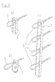
- FIG Fig. 5 For the transverse force transmission parallel to the joint various industrially manufactured fasteners are known, as shown schematically in FIG Fig. 5 are shown.
- continuous profile elements such as the Pfeifer VS® rail, PEEIEER VS® rail, Betomax Schlaufmax, Philipp rail, and also individual elements ( Fig. 5a ), b)), which are to ensure the transverse force transmission by repeatedly repeated arrangement of reinforcing loops in the precast joint above the other.
- the lengths of these rails and strips is for logistical reasons at about 1.20 m.
- To reach floor height several rail elements are joined together seamlessly. If fewer loops are needed in a joint, individual deposit boxes are used with only one loop at a distance. By way of example, two and two individual loops may be required in the floor above.
- the individual elements are, for example, the Pfeifer VS® box ( Fig. 5a )) and the Philipp connection loop ( Fig. 5b )) to disposal. Both have in common that it is an elongated storage box, at one end of a rope loop is arranged, which can be stored inside the storage box. The overall length is essentially matched to the one loop and much shorter than the rails and bars.
- the individual boxes are arranged at the bottom of the Vergussnut, and the opposing loops are folded out and connected overlapping by the introduced and hardening mortar.
- the US 6,308,478 B1 a connecting device with a plurality of, for example, four or more loop elements, which can be received in a common storage box and folded out of this.
- the invention is based on the finding that in compact fasteners with only one reinforcement loop or at the free ends of rail-like fasteners with transverse force stress no balance of power adjusts, in which the essential tensile forces are absorbed in the connection by reinforcing elements.
- the invention therefore aims to design and use the connecting element in particular even with compact dimensions such that the tensile forces that arise in the connection as a result of an oblique concrete strut by transverse force stress, are absorbed and forwarded by reinforcing elements.
- the invention provides that in a generic connection element, the penetration openings of the two reinforcing loop elements are provided near opposite ends of the storage box.
- two opposing reinforcing loops are in the bent-out state (final state) near the respective ends of the storage box.
- each individual, used according to the invention fastener a self-contained support behavior in which due to transverse force stress an inclined compression strut can form in concrete, which can be supported at their (imaginary) ends on the reinforcing loops of the connecting element to initiate excessive tensile forces in the concrete or mortar to avoid.
- an inclined compression strut can form in concrete, which can be supported at their (imaginary) ends on the reinforcing loops of the connecting element to initiate excessive tensile forces in the concrete or mortar to avoid.
- a harmful cracking in the connection area can be effectively prevented, which in addition to the load capacity and the durability and rigidity of the compound significantly increased.
- the connecting element used according to the invention has a simple construction and can be used without modification of the previous construction process without problems.
- a connecting element with exactly two reinforcing loop elements is an embodiment according to the invention.
- This is highly variable in use and has, in contrast to known individual elements, a significantly improved, self-contained load-bearing behavior.
- the maximum distance of the near-end penetrating openings from one end in the longitudinal direction of the storage box is less than 0.5 times a loop length by which the reinforcing loop elements project from the storage box in the bent-out state.
- a particularly compact connection element is provided.
- a concrete compression strut forming as a result of transverse force stress can be effectively supported at the proximal ends of the storage box with the perforation openings and thus the installed reinforcement loop elements arranged close to the edge, thereby further improving the load bearing behavior of the connection element.
- the maximum distance of the proximal penetrating openings from one end in the longitudinal direction of the storage box is less than 0.25 times, particularly preferably 0.1 times, the loop length.
- the length of the storage box is less than 2.5 times a loop length by which the reinforcing loop elements protrude in the bent-out state of the storage box.
- this configuration also ensures that the reinforcing loop elements in the installed state are sufficiently close to each other so that the inclination of a pressure strut between the reinforcing loop elements does not become too low and therefore the compressive forces that occur do not become excessively large.
- An even more compact connection element is obtained according to the invention if the length of the storage box is less than 1.5 times the loop length.
- the trolley bottom is profiled at least in sections by elevations and / or depressions. This ensures that the reinforcing loop elements of the connecting element also activates under transverse force stress before excessive deformation and cracking occurs in the area of the joint. It is particularly preferred that the elevations and / or depressions are provided adjacent to the penetration openings, so that adjusts the desired, closed support system with the involvement of the reinforcement loop elements.
- the connecting element according to the invention can be used individually or in combination with similar or different types of connecting elements. In this way, the carrying behavior of the overall connection is advantageously influenced by a locally limited measure.
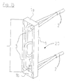
- Fig. 1a schematically shows a connecting element 20 according to a first embodiment of the present invention.
- the connecting element 20 serves for the transverse force joining of precast concrete elements to a joint with transverse forces parallel to the joint longitudinal direction and comprises a storage box 1 and two bendable reinforcing loop elements 3.
- the storage box 1 has an elongated, hollow box-like shape with a length L and two longitudinal ends 1a, 1b.
- a storage box floor 1c two openings 1 ', 1 "are provided, on which the reinforcement loop elements 3 penetrate the storage box 1.
- the reinforcement loop elements 3 may be, for example, beta steel bars or flexible cable elements which are connected at their free ends via a clamp 2, sleeve or the like.
- the length L of the storage box is designed such that the reinforcing loops 3 can be easily accommodated inside the storage box 1, as in FIG Fig. 1a shown.
- the length L of the storage box 1 is slightly less than 2.5 times the length of the loop 1.
- Fig. 1b shows a connecting element 20 according to a second preferred embodiment of the invention.
- This in Fig. 1b shown connecting element 20 differs from that according to the in Fig. 1a shown, first embodiment in the length L of the storage box 1.
- the maximum distance a of the penetration openings 1 ', 1 "in absolute terms is approximately the same as in the first embodiment, which, however, results in a somewhat larger ratio between the maximum distance a and length L of the storage box.
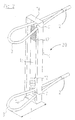
- FIG Fig. 2 schematically shown in a perspective view. This is different from the one in Fig. 1a shown first embodiment by profiling, which are provided in the form of recesses 12 in the storage box floor 1 c. In this case, the recesses 12 are provided in the present embodiment adjacent to the penetration openings 1 ', 1''.
- FIG. 2 the connecting element 20 with bent by the length of 1 Reinforcement loop elements 3, ie in the final state, which occupies the connecting element in a combination of precast concrete parts.
- the loop length 1 serves here, as in Fig. 2 shown, the storage box floor 1c.
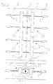
- FIG Fig. 4 A connection of precast concrete parts using the connecting element 20 according to the invention is shown schematically in FIG Fig. 4 showing both a vertical and a horizontal sectional view of the connection.
- the connecting elements 20 according to the invention are provided in end-side potting grooves 11 of precast concrete elements 5 to be joined together.
- the precast concrete elements 5 are placed side by side with their end faces in such a way that a gap 10 forms in the region of the grouting grooves 11 and is later filled with grout.
- the reinforcing loop elements 3 are bent out of the custody boxes 1, so that the reinforcing loop elements 3 of opposing connecting elements 20 overlap.
- a mounting bar 8 made of reinforcing steel is guided by the overlaps. Finally, the grouting of the joint is made to connect the finished parts 5 non-positively with each other.
- the connecting elements 20, as in the upper part of Fig. 4 can be seen in the vertical section, preferably evenly arranged over the precast concrete elements 5.
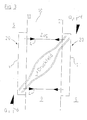
- a model for the in the range of two interconnected by connecting elements 20 precast concrete 5 adjusting behavior is schematically in Fig. 3 shown.
- a transverse force stress Q whose effective direction is indicated schematically by arrows 6 in FIG Fig. 3 is specified, formed between the precast concrete 5 in the grout or concrete a pressure field, by a inclined concrete strut 7 can be modeled.
- the model, inclined concrete strut 7 is supported at its ends on the storage boxes 1 of the connecting elements 20, wherein both the Verwahrkastenenden 1 a, 1b and the recesses 12 of the deposit box bottom 1 c contribute to improved support and load transfer of the strut 7.
- the forces 5 aroused by the strut 7 must be taken up and down.
- the preferred embodiments described above each have exactly two reinforcing loop elements, since this results in particularly compact and versatile connecting elements with a closed carrying behavior.
Landscapes
- Engineering & Computer Science (AREA)
- Architecture (AREA)
- Mechanical Engineering (AREA)
- Civil Engineering (AREA)
- Structural Engineering (AREA)
- Joining Of Building Structures In Genera (AREA)
- Reinforcement Elements For Buildings (AREA)
- Flanged Joints, Insulating Joints, And Other Joints (AREA)
- Adornments (AREA)
Priority Applications (1)
| Application Number | Priority Date | Filing Date | Title |
|---|---|---|---|
| PL09153597T PL2055846T3 (pl) | 2004-02-11 | 2005-02-10 | Zastosowanie elementów łączących do łączenia prefabrykowanych elementów betonowych |
Applications Claiming Priority (2)
| Application Number | Priority Date | Filing Date | Title |
|---|---|---|---|
| DE202004002110U DE202004002110U1 (de) | 2004-02-11 | 2004-02-11 | Verbindungselement zur Verbindung von Betonfertigteilen |
| EP05002768A EP1589156B1 (de) | 2004-02-11 | 2005-02-10 | Verbindungselement zur Verbindung von Betonfertigteilen |
Related Parent Applications (1)
| Application Number | Title | Priority Date | Filing Date |
|---|---|---|---|
| EP05002768A Division EP1589156B1 (de) | 2004-02-11 | 2005-02-10 | Verbindungselement zur Verbindung von Betonfertigteilen |
Publications (2)
| Publication Number | Publication Date |
|---|---|
| EP2055846A1 EP2055846A1 (de) | 2009-05-06 |
| EP2055846B1 true EP2055846B1 (de) | 2012-10-10 |
Family
ID=34716806
Family Applications (2)
| Application Number | Title | Priority Date | Filing Date |
|---|---|---|---|
| EP09153597A Expired - Lifetime EP2055846B1 (de) | 2004-02-11 | 2005-02-10 | Verwendung von Verbindungselementen zur Verbindung von Betonfertigteilen |
| EP05002768A Expired - Lifetime EP1589156B1 (de) | 2004-02-11 | 2005-02-10 | Verbindungselement zur Verbindung von Betonfertigteilen |
Family Applications After (1)
| Application Number | Title | Priority Date | Filing Date |
|---|---|---|---|
| EP05002768A Expired - Lifetime EP1589156B1 (de) | 2004-02-11 | 2005-02-10 | Verbindungselement zur Verbindung von Betonfertigteilen |
Country Status (6)
| Country | Link |
|---|---|
| EP (2) | EP2055846B1 (da) |
| AT (1) | ATE432393T1 (da) |
| DE (2) | DE202004002110U1 (da) |
| DK (2) | DK1589156T3 (da) |
| ES (2) | ES2327047T3 (da) |
| PL (2) | PL2055846T3 (da) |
Families Citing this family (9)
| Publication number | Priority date | Publication date | Assignee | Title |
|---|---|---|---|---|
| DE102008013206B4 (de) * | 2008-03-07 | 2019-12-05 | P & T Technische Mörtel GmbH & Co. KG | Verfahren zum Verbinden von Betonfertigteilen und damit hergestelltes Bauwerk |
| DE102008063525B4 (de) * | 2008-12-18 | 2017-03-09 | P & T Technische Mörtel GmbH & Co. KG | Verfahren und Vorrichtung zur Verbindung von Betonfertigteilen |
| DE202009000910U1 (de) | 2009-01-23 | 2010-06-17 | Philipp Gmbh | Vorrichtung zur Halterung von Seilschlaufen |
| DE102010003272A1 (de) | 2010-03-25 | 2011-09-29 | Georg Weidner | Vorrichtung zur Herstellung eines Verbunds zwischen Betonfertigteilen |
| DE202010010127U1 (de) | 2010-07-12 | 2011-10-24 | Pfeifer Seil- Und Hebetechnik Gmbh | Verwahrungsbox und Verwendung einer Verwahrungsbox |
| RU2499103C1 (ru) * | 2012-05-05 | 2013-11-20 | Открытое акционерное общество Центральный научно-исследовательский и проектный институт жилых и общественных зданий (ОАО "ЦНИИЭП жилища") | Способ изготовления сборно-монолитного узла соединения колонны с ригелем |
| CN110185155B (zh) * | 2019-06-25 | 2024-03-15 | 中国建筑标准设计研究院有限公司 | 一种预制构件的接缝连接器及预制墙体系及其施工方法 |
| DE102020203108A1 (de) | 2020-03-11 | 2021-09-16 | Pfeifer Holding Gmbh & Co. Kg | Verbindungselement zum kraftschlüssigen Verbinden von Betonbauteilen |
| CN118065554B (zh) * | 2024-03-26 | 2024-11-15 | 河北顺安远大环保科技股份有限公司 | 一种全预制混凝土楼板拼接处企口结构 |
Family Cites Families (10)
| Publication number | Priority date | Publication date | Assignee | Title |
|---|---|---|---|---|
| EP0103060B2 (de) * | 1982-09-10 | 1991-11-06 | Pawe Ag | Armierungseisenhalter zur Verwendung bei Anschlussbetonierungen und Verfahren zur Herstellung desselben |
| DE8336278U1 (de) | 1983-12-17 | 1984-03-29 | Hoff, Walter, 4000 Düsseldorf | Verwahrungselement fuer bewehrungen |
| FR2710091A1 (fr) * | 1993-09-16 | 1995-03-24 | Sauveplane Pierre | Dispositif de mise en place et de positionnement d'armature dans des coffrages pour béton armé. |
| DE9407998U1 (de) * | 1994-05-13 | 1994-07-14 | Dausend, Hans-Werner, 42279 Wuppertal | Verwahrkasten für Anschluß-Bewehrungseisen |
| DE29612573U1 (de) * | 1996-07-20 | 1997-11-20 | Pfeifer Seil- und Hebetechnik GmbH & Co, 87700 Memmingen | Vorrichtung zum Verbund von Betonfertigteilen |
| DE29711542U1 (de) * | 1997-07-03 | 1998-10-29 | Pfeifer Seil- und Hebetechnik GmbH & Co, 87700 Memmingen | Vorrichtung zum Verbinden von armierten Betonteilen |
| CZ296916B6 (cs) | 1997-07-03 | 2006-07-12 | Pfeifer Seil- Und Hebetechnik Gmbh & Co. | Zarízení ke spojování armovaných betonových dílcua zpusob výroby spojení armovaných betonových dílcu |
| DE29906417U1 (de) * | 1999-04-12 | 2000-09-14 | Reuß GmbH & Co. KG, 42277 Wuppertal | Vorrichtung zum Verwahren mindestens einer elastisch verformbaren Seilschlaufe in der Oberfläche von Betonfertigteile |
| DE20111702U1 (de) * | 2001-07-18 | 2002-11-21 | Pfeifer Holding GmbH & Co. KG, 87700 Memmingen | Vorrichtung zum Verbund von Betonfertigteilen |
| DE20319471U1 (de) * | 2003-12-16 | 2005-01-20 | Pfeifer Holding Gmbh & Co. Kg | Verbindungsfuge für den Kraftschluß von Betonfertigteilen |
-
2004
- 2004-02-11 DE DE202004002110U patent/DE202004002110U1/de not_active Expired - Lifetime
-
2005
- 2005-02-10 ES ES05002768T patent/ES2327047T3/es not_active Expired - Lifetime
- 2005-02-10 DE DE502005007331T patent/DE502005007331D1/de not_active Expired - Lifetime
- 2005-02-10 PL PL09153597T patent/PL2055846T3/pl unknown
- 2005-02-10 PL PL05002768T patent/PL1589156T3/pl unknown
- 2005-02-10 DK DK05002768T patent/DK1589156T3/da active
- 2005-02-10 ES ES09153597T patent/ES2396476T3/es not_active Expired - Lifetime
- 2005-02-10 EP EP09153597A patent/EP2055846B1/de not_active Expired - Lifetime
- 2005-02-10 DK DK09153597.1T patent/DK2055846T3/da active
- 2005-02-10 EP EP05002768A patent/EP1589156B1/de not_active Expired - Lifetime
- 2005-02-10 AT AT05002768T patent/ATE432393T1/de active
Also Published As
| Publication number | Publication date |
|---|---|
| EP1589156A2 (de) | 2005-10-26 |
| ES2327047T3 (es) | 2009-10-23 |
| DE502005007331D1 (de) | 2009-07-09 |
| EP1589156B1 (de) | 2009-05-27 |
| EP1589156A3 (de) | 2008-05-21 |
| DE202004002110U1 (de) | 2005-06-30 |
| EP2055846A1 (de) | 2009-05-06 |
| DK2055846T3 (da) | 2013-01-07 |
| ES2396476T3 (es) | 2013-02-21 |
| ATE432393T1 (de) | 2009-06-15 |
| PL1589156T3 (pl) | 2009-10-30 |
| PL2055846T3 (pl) | 2013-03-29 |
| DK1589156T3 (da) | 2009-09-07 |
Similar Documents
| Publication | Publication Date | Title |
|---|---|---|
| DE1807716A1 (de) | Vorgefertigtes,transportables Raumelement zur Herstellung von Bauwerken | |
| EP0258338A1 (de) | Befestigungselement für die mantelbetonbauweise | |
| WO2022049065A1 (de) | Rahmenschalungselement und rahmenschalungssystem, verwendung einer leiste in einem rahmenschalungssystem | |
| EP2055846B1 (de) | Verwendung von Verbindungselementen zur Verbindung von Betonfertigteilen | |
| EP3183401A1 (de) | Betonkonstruktion in modulbauweise | |
| EP2172601B1 (de) | Frei schwebende Treppe | |
| AT402084B (de) | Verlorenes schalungselement | |
| DE69512411T2 (de) | Flüssigkeitsrohr | |
| DE102019215009A1 (de) | Holz-Beton-Verbundplatte, insbesondere zum Einsatz als Gebäude-Decken- oder -Wandplatte und Verfahren zu deren Herstellung | |
| EP0442130B1 (de) | Bauteil als Fugen- und/oder Dilatations- und/oder Kragplattenelement für zementgebundene, bewehrte Baukonstruktionen | |
| DE9409626U1 (de) | Balkonkonstruktion | |
| EP1101883B1 (de) | Verfahren zur Herstellung eines Bewehrungsanschlusses zwischen einem bewehrten Betonbauteil und einem Anschlussbauteil | |
| DE19835900C2 (de) | Betonfertigbauteile sowie unter Verwendung von Betonfertigbauteilgruppen errichtetes Gebäude | |
| EP3346058A1 (de) | Gabionenwandmodul und verfahren zur herstellung einer gabionenwand mit wenigstens einem gabionenwandmodul | |
| DE102016204383A1 (de) | Schalungselement | |
| EP0645501B1 (de) | Verfahren zur Herstellung von vorgefertigten Modulen für die Erstellung von Bauwerken und vorgefertiger Modul | |
| AT412359B (de) | Schalung | |
| EP1645693A1 (de) | Anbausysteme für von Baukörpern auskragende Konstruktionen | |
| EP0737786A1 (de) | Abfangvorrichtung für ein Mauerwerk, insbesondere als Verblendsturz mit Bewehrung | |
| DE29505448U1 (de) | Randschalungselement | |
| EP3130713B1 (de) | Bauwerk und verfahren zur herstellung eines bauwerks | |
| EP0480295B1 (de) | Bausatz zum Errichten eines Wohn- oder Ferienhauses | |
| DE2651590A1 (de) | Bohltraeger und bausatz fuer bohltraegerwaende | |
| DE4424361C2 (de) | Schalungselement | |
| EP3995644A1 (de) | Fassadenverkleidungs-gabionenkonstruktion |
Legal Events
| Date | Code | Title | Description |
|---|---|---|---|
| PUAI | Public reference made under article 153(3) epc to a published international application that has entered the european phase |
Free format text: ORIGINAL CODE: 0009012 |
|
| AC | Divisional application: reference to earlier application |
Ref document number: 1589156 Country of ref document: EP Kind code of ref document: P |
|
| AK | Designated contracting states |
Kind code of ref document: A1 Designated state(s): AT BE BG CH CY CZ DE DK EE ES FI FR GB GR HU IE IS IT LI LT LU MC NL PL PT RO SE SI SK TR |
|
| AX | Request for extension of the european patent |
Extension state: AL BA HR LV MK YU |
|
| 17P | Request for examination filed |
Effective date: 20090519 |
|
| AKX | Designation fees paid |
Designated state(s): AT BE BG CH CY CZ DE DK EE ES FI FR GB GR HU IE IS IT LI LT LU MC NL PL PT RO SE SI SK TR |
|
| 17Q | First examination report despatched |
Effective date: 20120127 |
|
| GRAP | Despatch of communication of intention to grant a patent |
Free format text: ORIGINAL CODE: EPIDOSNIGR1 |
|
| GRAS | Grant fee paid |
Free format text: ORIGINAL CODE: EPIDOSNIGR3 |
|
| GRAA | (expected) grant |
Free format text: ORIGINAL CODE: 0009210 |
|
| AC | Divisional application: reference to earlier application |
Ref document number: 1589156 Country of ref document: EP Kind code of ref document: P |
|
| AK | Designated contracting states |
Kind code of ref document: B1 Designated state(s): AT BE BG CH CY CZ DE DK EE ES FI FR GB GR HU IE IS IT LI LT LU MC NL PL PT RO SE SI SK TR |
|
| REG | Reference to a national code |
Ref country code: GB Ref legal event code: FG4D Free format text: NOT ENGLISH |
|
| REG | Reference to a national code |
Ref country code: AT Ref legal event code: REF Ref document number: 579055 Country of ref document: AT Kind code of ref document: T Effective date: 20121015 Ref country code: CH Ref legal event code: NV Representative=s name: NOVAGRAAF INTERNATIONAL SA Ref country code: CH Ref legal event code: EP |
|
| REG | Reference to a national code |
Ref country code: IE Ref legal event code: FG4D Free format text: LANGUAGE OF EP DOCUMENT: GERMAN |
|
| REG | Reference to a national code |
Ref country code: RO Ref legal event code: EPE |
|
| REG | Reference to a national code |
Ref country code: SE Ref legal event code: TRGR |
|
| REG | Reference to a national code |
Ref country code: DE Ref legal event code: R096 Ref document number: 502005013183 Country of ref document: DE Effective date: 20121213 |
|
| REG | Reference to a national code |
Ref country code: NL Ref legal event code: T3 |
|
| REG | Reference to a national code |
Ref country code: DK Ref legal event code: T3 |
|
| REG | Reference to a national code |
Ref country code: ES Ref legal event code: FG2A Ref document number: 2396476 Country of ref document: ES Kind code of ref document: T3 Effective date: 20130221 |
|
| PG25 | Lapsed in a contracting state [announced via postgrant information from national office to epo] |
Ref country code: SI Free format text: LAPSE BECAUSE OF FAILURE TO SUBMIT A TRANSLATION OF THE DESCRIPTION OR TO PAY THE FEE WITHIN THE PRESCRIBED TIME-LIMIT Effective date: 20121010 |
|
| REG | Reference to a national code |
Ref country code: LT Ref legal event code: MG4D |
|
| REG | Reference to a national code |
Ref country code: PL Ref legal event code: T3 |
|
| REG | Reference to a national code |
Ref country code: SK Ref legal event code: T3 Ref document number: E 13323 Country of ref document: SK |
|
| PG25 | Lapsed in a contracting state [announced via postgrant information from national office to epo] |
Ref country code: LT Free format text: LAPSE BECAUSE OF FAILURE TO SUBMIT A TRANSLATION OF THE DESCRIPTION OR TO PAY THE FEE WITHIN THE PRESCRIBED TIME-LIMIT Effective date: 20121010 Ref country code: IS Free format text: LAPSE BECAUSE OF FAILURE TO SUBMIT A TRANSLATION OF THE DESCRIPTION OR TO PAY THE FEE WITHIN THE PRESCRIBED TIME-LIMIT Effective date: 20130210 |
|
| PG25 | Lapsed in a contracting state [announced via postgrant information from national office to epo] |
Ref country code: GR Free format text: LAPSE BECAUSE OF FAILURE TO SUBMIT A TRANSLATION OF THE DESCRIPTION OR TO PAY THE FEE WITHIN THE PRESCRIBED TIME-LIMIT Effective date: 20130111 Ref country code: PT Free format text: LAPSE BECAUSE OF FAILURE TO SUBMIT A TRANSLATION OF THE DESCRIPTION OR TO PAY THE FEE WITHIN THE PRESCRIBED TIME-LIMIT Effective date: 20130211 |
|
| PLBI | Opposition filed |
Free format text: ORIGINAL CODE: 0009260 |
|
| PLBI | Opposition filed |
Free format text: ORIGINAL CODE: 0009260 |
|
| REG | Reference to a national code |
Ref country code: HU Ref legal event code: AG4A Ref document number: E016101 Country of ref document: HU |
|
| PG25 | Lapsed in a contracting state [announced via postgrant information from national office to epo] |
Ref country code: BG Free format text: LAPSE BECAUSE OF FAILURE TO SUBMIT A TRANSLATION OF THE DESCRIPTION OR TO PAY THE FEE WITHIN THE PRESCRIBED TIME-LIMIT Effective date: 20130110 Ref country code: EE Free format text: LAPSE BECAUSE OF FAILURE TO SUBMIT A TRANSLATION OF THE DESCRIPTION OR TO PAY THE FEE WITHIN THE PRESCRIBED TIME-LIMIT Effective date: 20121010 |
|
| 26 | Opposition filed |
Opponent name: HALFEN GMBH Effective date: 20130705 |
|
| PLAX | Notice of opposition and request to file observation + time limit sent |
Free format text: ORIGINAL CODE: EPIDOSNOBS2 |
|
| 26 | Opposition filed |
Opponent name: PHILIPP GMBH Effective date: 20130710 |
|
| PG25 | Lapsed in a contracting state [announced via postgrant information from national office to epo] |
Ref country code: MC Free format text: LAPSE BECAUSE OF NON-PAYMENT OF DUE FEES Effective date: 20130228 |
|
| REG | Reference to a national code |
Ref country code: DE Ref legal event code: R026 Ref document number: 502005013183 Country of ref document: DE Effective date: 20130705 |
|
| PG25 | Lapsed in a contracting state [announced via postgrant information from national office to epo] |
Ref country code: CY Free format text: LAPSE BECAUSE OF FAILURE TO SUBMIT A TRANSLATION OF THE DESCRIPTION OR TO PAY THE FEE WITHIN THE PRESCRIBED TIME-LIMIT Effective date: 20121010 |
|
| PLBB | Reply of patent proprietor to notice(s) of opposition received |
Free format text: ORIGINAL CODE: EPIDOSNOBS3 |
|
| PLBP | Opposition withdrawn |
Free format text: ORIGINAL CODE: 0009264 |
|
| PLBP | Opposition withdrawn |
Free format text: ORIGINAL CODE: 0009264 |
|
| PLBD | Termination of opposition procedure: decision despatched |
Free format text: ORIGINAL CODE: EPIDOSNOPC1 |
|
| PG25 | Lapsed in a contracting state [announced via postgrant information from national office to epo] |
Ref country code: LU Free format text: LAPSE BECAUSE OF NON-PAYMENT OF DUE FEES Effective date: 20130210 |
|
| PLBM | Termination of opposition procedure: date of legal effect published |
Free format text: ORIGINAL CODE: 0009276 |
|
| STAA | Information on the status of an ep patent application or granted ep patent |
Free format text: STATUS: OPPOSITION PROCEDURE CLOSED |
|
| 27C | Opposition proceedings terminated |
Effective date: 20150508 |
|
| REG | Reference to a national code |
Ref country code: FR Ref legal event code: PLFP Year of fee payment: 12 |
|
| REG | Reference to a national code |
Ref country code: FR Ref legal event code: PLFP Year of fee payment: 13 |
|
| REG | Reference to a national code |
Ref country code: FR Ref legal event code: PLFP Year of fee payment: 14 |
|
| PGFP | Annual fee paid to national office [announced via postgrant information from national office to epo] |
Ref country code: NL Payment date: 20210218 Year of fee payment: 17 Ref country code: IE Payment date: 20210216 Year of fee payment: 17 |
|
| PGFP | Annual fee paid to national office [announced via postgrant information from national office to epo] |
Ref country code: SE Payment date: 20210222 Year of fee payment: 17 |
|
| REG | Reference to a national code |
Ref country code: SE Ref legal event code: EUG |
|
| REG | Reference to a national code |
Ref country code: NL Ref legal event code: MM Effective date: 20220301 |
|
| PG25 | Lapsed in a contracting state [announced via postgrant information from national office to epo] |
Ref country code: SE Free format text: LAPSE BECAUSE OF NON-PAYMENT OF DUE FEES Effective date: 20220211 |
|
| PG25 | Lapsed in a contracting state [announced via postgrant information from national office to epo] |
Ref country code: NL Free format text: LAPSE BECAUSE OF NON-PAYMENT OF DUE FEES Effective date: 20220301 |
|
| PG25 | Lapsed in a contracting state [announced via postgrant information from national office to epo] |
Ref country code: IE Free format text: LAPSE BECAUSE OF NON-PAYMENT OF DUE FEES Effective date: 20220210 |
|
| P01 | Opt-out of the competence of the unified patent court (upc) registered |
Effective date: 20230525 |
|
| PGFP | Annual fee paid to national office [announced via postgrant information from national office to epo] |
Ref country code: ES Payment date: 20240304 Year of fee payment: 20 |
|
| PGFP | Annual fee paid to national office [announced via postgrant information from national office to epo] |
Ref country code: AT Payment date: 20240202 Year of fee payment: 20 |
|
| PGFP | Annual fee paid to national office [announced via postgrant information from national office to epo] |
Ref country code: RO Payment date: 20240205 Year of fee payment: 20 Ref country code: HU Payment date: 20240118 Year of fee payment: 20 Ref country code: FI Payment date: 20240202 Year of fee payment: 20 Ref country code: DE Payment date: 20240201 Year of fee payment: 20 Ref country code: CZ Payment date: 20240119 Year of fee payment: 20 Ref country code: GB Payment date: 20240201 Year of fee payment: 20 Ref country code: CH Payment date: 20240301 Year of fee payment: 20 Ref country code: SK Payment date: 20240119 Year of fee payment: 20 |
|
| PGFP | Annual fee paid to national office [announced via postgrant information from national office to epo] |
Ref country code: TR Payment date: 20240119 Year of fee payment: 20 Ref country code: PL Payment date: 20240115 Year of fee payment: 20 Ref country code: IT Payment date: 20240201 Year of fee payment: 20 Ref country code: FR Payment date: 20240201 Year of fee payment: 20 Ref country code: DK Payment date: 20240201 Year of fee payment: 20 Ref country code: BE Payment date: 20240201 Year of fee payment: 20 |
|
| REG | Reference to a national code |
Ref country code: DE Ref legal event code: R071 Ref document number: 502005013183 Country of ref document: DE |
|
| REG | Reference to a national code |
Ref country code: CH Ref legal event code: PL |
|
| REG | Reference to a national code |
Ref country code: DK Ref legal event code: EUP Expiry date: 20250210 |
|
| REG | Reference to a national code |
Ref country code: SK Ref legal event code: MK4A Ref document number: E 13323 Country of ref document: SK Expiry date: 20250210 Ref country code: ES Ref legal event code: FD2A Effective date: 20250226 |
|
| REG | Reference to a national code |
Ref country code: GB Ref legal event code: PE20 Expiry date: 20250209 |
|
| REG | Reference to a national code |
Ref country code: AT Ref legal event code: MK07 Ref document number: 579055 Country of ref document: AT Kind code of ref document: T Effective date: 20250210 |
|
| PG25 | Lapsed in a contracting state [announced via postgrant information from national office to epo] |
Ref country code: ES Free format text: LAPSE BECAUSE OF EXPIRATION OF PROTECTION Effective date: 20250211 |
|
| PG25 | Lapsed in a contracting state [announced via postgrant information from national office to epo] |
Ref country code: CZ Free format text: LAPSE BECAUSE OF EXPIRATION OF PROTECTION Effective date: 20250210 |
|
| PG25 | Lapsed in a contracting state [announced via postgrant information from national office to epo] |
Ref country code: SK Free format text: LAPSE BECAUSE OF EXPIRATION OF PROTECTION Effective date: 20250210 Ref country code: GB Free format text: LAPSE BECAUSE OF EXPIRATION OF PROTECTION Effective date: 20250209 |
|
| REG | Reference to a national code |
Ref country code: BE Ref legal event code: MK Effective date: 20250210 |