EP1589156A2 - Verbindungselement zur Verbindung von Betonfertigteilen - Google Patents
Verbindungselement zur Verbindung von Betonfertigteilen Download PDFInfo
- Publication number
- EP1589156A2 EP1589156A2 EP05002768A EP05002768A EP1589156A2 EP 1589156 A2 EP1589156 A2 EP 1589156A2 EP 05002768 A EP05002768 A EP 05002768A EP 05002768 A EP05002768 A EP 05002768A EP 1589156 A2 EP1589156 A2 EP 1589156A2
- Authority
- EP
- European Patent Office
- Prior art keywords
- storage box
- connecting element
- elements
- loop
- loop elements
- Prior art date
- Legal status (The legal status is an assumption and is not a legal conclusion. Google has not performed a legal analysis and makes no representation as to the accuracy of the status listed.)
- Granted
Links
Images


Classifications
-
- E—FIXED CONSTRUCTIONS
- E04—BUILDING
- E04G—SCAFFOLDING; FORMS; SHUTTERING; BUILDING IMPLEMENTS OR AIDS, OR THEIR USE; HANDLING BUILDING MATERIALS ON THE SITE; REPAIRING, BREAKING-UP OR OTHER WORK ON EXISTING BUILDINGS
- E04G21/00—Preparing, conveying, or working-up building materials or building elements in situ; Other devices or measures for constructional work
- E04G21/12—Mounting of reinforcing inserts; Prestressing
- E04G21/125—Reinforcement continuity box
- E04G21/126—Reinforcement continuity box for cable loops
Definitions
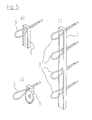
- the individual elements are, for example, the Pfeifer VS® box ( Figure 5a)) and the Philipp connection loop (Figure 5b)) Available. Both are mean that it is one elongated storage box, at one end a rope loop is arranged inside the Storage box can be kept. The total length is essentially tuned to the one loop and much shorter than the rails and bars. In the final state the individual boxes are arranged at the bottom of Vergussnut, and the opposite loops become unfolded and overlapped by the introduced and hardening mortar connected.
- the invention is based on the finding that at compact connectors with only one Reinforcement bend or at rail ends at free ends Connecting elements with transverse force stress no Balance of forces sets, in which the essential Tensile forces in the connection through reinforcing elements be recorded.
- the invention therefore focuses on the connecting element especially in compact dimensions such To design that the tensile forces in the connection due to an oblique concrete strut by Transverse force stress caused by reinforcing elements be recorded and forwarded.
- the connecting element in a generic Connecting element, the penetration openings of two Reinforcement loop elements near opposite ends of the Deposit box are provided.
- the connecting element according to the invention two opposite reinforcing loops in the bent out State (final state) near the respective ends of the Storage box.
- the present invention is not limited to a particular Number of loop elements is limited Connecting element with exactly two Reinforcement loop elements a particularly preferred Embodiment is. This is highly variable and can be used has in contrast to known individual elements significantly improved, self-contained load-bearing behavior.
- the maximum distance of near-end Penetration openings from one end in the longitudinal direction of Storage box is less than 0.5 times one Loop length around which the reinforcement loop elements in the bent out state of the storage box protruding.
- This will be a particularly compact connection element provided.
- the maximum distance of the near-penetration openings from one end into Longitudinal direction of the storage box is less than 0.25 times, more preferably 0.1 times the loop length.
- the connecting element according to the invention is according to a Continuing provided that the length of the custody box less than 2.5 times a loop length to which bent out the reinforcement loop elements in the Condition of the storage box protrude. simultaneously however, this configuration also ensures that the Reinforcement loop elements in installed condition sufficiently close to each other, so that the tendency of a arising between the reinforcing loop elements Strut is not too low and the occurring Compressive forces therefore do not become excessively large.
- One more compact connecting element is obtained according to the invention, if the length of the storage box is less than 1.5 times the loop length.
- At least two reinforcement loop elements in the recorded in the storage box state each other are facing and preferably at least partially overlap, so that the connecting element according to the invention hardly larger dimensions than a known one Single loop element, but a dramatically improved Has carrying behavior.
- Trunk floor at least in sections by surveys and / or depressions is profiled. This will ensured that the reinforcement loop elements of the Connecting element also activated in case of transverse force stress Becoming an excessive deformation and cracking in the area of the connection. It is special preferred that the elevations and / or depressions are provided adjacent to the penetration openings, so that the desired, closed support system under Integration of the reinforcement loop elements sets.
- the connecting element according to the invention can be used individually or in Combination with similar or different Connecting elements are used. This way will by a locally limited measure the carrying behavior of the Overall connection favorably influenced.
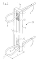
- Fig. 1a shows schematically a connecting element 20 according to a first embodiment of the present invention.
- the Connecting element 20 serves for transverse force-locking Connecting precast concrete elements to a joint with transverse forces parallel to the joint longitudinal direction and includes a Deposit box 1 and two subscribebiegbare Reinforcement loop elements 3.
- the storage box 1 has an elongated, hollow box-like shape with a length L and two longitudinal end faces 1a, 1b.
- Trunk bottom 1c are two openings 1 ', 1' 'provided, at which the reinforcement loop elements 3 the Penetrate Depository 1.
- the reinforcement loop elements 3 may be For example, around rebar or flexible Rope elements act at their free ends over a Terminal 2, sleeve or the like are connected.
- the penetration openings 1 ', 1' ' are close to the invention the opposite ends 1a, 1b of the storage box. 1 provided, as shown in Fig. 1a. It is preferred that shown in Fig. 1a, the maximum distance a of Penetration openings 1 ', 1' 'from the ends 1a, 1b of the Storage box 1 is less than 0.5 times the below defined loop length 1. Above, the maximum distance a of the penetration openings 1 ', 1' 'of the ends 1a, 1b of the storage box 1 at least for compact fasteners preferably less than that 0.1 times the length L of the storage box.
- the length L of the storage box is designed such that that the reinforcement loops 3 easily inside the Storage box 1 can be received, as shown in Fig. 1a shown.
- the loops 3 are different from the state the technology facing each other. Starting from this state the loops 3 can be bent out of the storage box 1 to reach the final state shown in FIG. 2, in which the loops 3 to a loop length 1 of the Deposit box 1 protrude.
- the length L of the storage box 1 is something less than 2.5 times the loop length 1.
- Fig. 1b shows a connecting element 20 according to a second preferred embodiment of the invention. That in Fig. 1b shown connecting element 20 differs from the one according to the first shown in Fig. 1a Embodiment in the length L of the storage box 1. This is in the second embodiment shown in Fig. 1b considerably less and is slightly less than 1.5 times the loop length 1. This results in a still more compact connecting element, in which the loops 3 in folded state are arranged overlapping.
- the maximum distance a is the Penetration openings 1 ', 1' 'in the second absolutely about the same size as in the first embodiment, which, however, something greater ratio between maximum distance a and length L of the deposit box.
- FIG Perspective view shown A third preferred embodiment of the invention Connecting element 20 is shown schematically in FIG Perspective view shown. This is different from of the first embodiment shown in Fig. 1a Profiles in the form of recesses 12 in the Trunk floor 1c are provided. Here are the Recesses 12 in the present embodiment adjacent to the penetration openings 1 ', 1' 'provided.
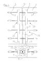
- Fig. 2 shows the connecting element 20 with the order Length 1 of bent-out reinforcing loop elements 3, i. in the final state, which the connecting element in a Connection of precast concrete occupies.
- the loop length 1 is used here, as in Fig. 2 shown, the storage box floor 1c.
- FIG Fig. 4 shows both a vertical and a horizontal sectional view of the connection shows.
- FIG Fig. 4 shows both a vertical and a horizontal sectional view of the connection shows.
- the inventive Connecting elements 20 in frontal Vergussnuten 11 of provided to be joined together precast concrete 5.
- the precast concrete elements 5 are with their end faces like this placed next to each other, that is in the area of Vergussnuten 11 forms a gap 10, which later filled with grout becomes.
- After the juxtaposition of precast concrete 5 Be the reinforcement loop elements 3 from the Deposit boxes 1 bent out, so that the Reinforcement loop elements 3 opposite each other Overlap fasteners 20.
- FIG. 3 A model for working in the field of two together Connecting elements 20 connected precast concrete 5 adjusting load-bearing behavior is shown schematically in FIG. 3 shown.
- their direction of action schematically by arrows 6 in Fig. 3rd is specified forms between the precast concrete 5 in the grout or concrete a pressure field, which by a inclined concrete strut 7 can be modeled.
- the model, inclined concrete strut 7 is based on their Ends on the storage boxes 1 of the connecting elements 20, wherein both the Verwahrkastenenden 1a, 1b and the Wells 12 of the deposit box bottom 1c to a improved support and load transfer of the strut 7 contribute.
- the preferred embodiments described above each have exactly two reinforcing loop elements, since This makes it particularly compact and versatile Connecting elements with a self-contained Trag arise.
- the fasteners with a larger number of reinforcing loop elements if at least the two outermost reinforcing loop elements close the ends of the storage box are arranged.
Landscapes
- Engineering & Computer Science (AREA)
- Architecture (AREA)
- Mechanical Engineering (AREA)
- Civil Engineering (AREA)
- Structural Engineering (AREA)
- Joining Of Building Structures In Genera (AREA)
- Reinforcement Elements For Buildings (AREA)
- Flanged Joints, Insulating Joints, And Other Joints (AREA)
- Adornments (AREA)
Abstract
Description
- Fig. 1a
- zeigt schematisch eine Perspektivansicht einer ersten Ausführungsform des erfindungsgemäßen Verbindungselements;
- Fig. 1b
- zeigt schematisch eine Perspektivansicht einer zweiten Ausführungsform des erfindungsgemäßen Verbindungselements;
- Fig. 2
- zeigt schematisch eine Perspektivansicht einer dritten Ausführungsform des erfindungsgemäßen Verbindungselements;
- Fig. 3
- zeigt schematisch eine Modellvorstellung des Tragverhaltens zweier miteinander durch Verbindungselemente verbundener Betonfertigteile;
- Fig. 4
- zeigt schematisch eine querkraftschlüssige Verbindung von Betonfertigteilen unter Einsatz des erfindungsgemäßen Verbindungselements;
- Fig. 5
- zeigt schematisch Verbindungselemente gemäß dem Stand der Technik.
- 1
- Verwahrkasten für die Bewehrungsschlaufen
- 1a, b
- Verwahrkastenenden
- 1c
- Verwahrkastenboden
- 1', 1''
- Durchdringungsöffnungen
- 2
- Endverankerung der Bewehrungsschlaufe
- 3
- Bewehrungsschlaufe aus Drahtseil oder Betonstahl
- 4
- Horizontale Zugkraft
- 5
- Betonfertigteil wand- oder stützenartig
- 6
- Querkraft parallel zur Wandfuge
- 7
- Schräge Druckstrebe im Vergussbereich
- 8
- Montagestab aus Betonstahl
- 9
- Bereich mit Vergussmörtel
- 10
- Fuge zwischen zwei Betonfertigteilen
- 11
- Vergussnut
- 12
- Vertiefungen oder Erhebungen zur Verbesserung des Druckstrebenangriffs
- 20
- Verbindungselement
- L
- Länge des Verwahrkastens
- l
- Schlaufenlänge
Claims (9)
- Verbindungselement (20) zum querkraftschlüssigen Verbinden von Betonfertigteilen (5) an einer Fuge (10) mit Querkräften parallel zur Fugenlängsrichtung, umfassend einen bevorzugt länglichen Verwahrkasten (1) und mindestens zwei Bewehrungsschlaufenelemente (3), die in dem Verwahrkasten (1) aufnehmbar und aus diesem herausbiegbar sind, wobei die Bewehrungsschlaufenelemente (3) den Verwahrkasten (1) im Bereich jeweils einer Durchdringungsöffnung (1', 1'') des Verwahrkastens (1) durchdringen,
dadurch gekennzeichnet, dass
die Durchdringungsöffnungen (1', 1'') zweier Bewehrungsschlaufenelemente (3) nahe gegenüberliegender Enden (1a, 1b) des Verwahrkastens (1) vorgesehen sind. - Verbindungselement nach Anspruch 1, dadurch gekennzeichnet, dass es genau zwei Bewehrungsschlaufenelemente (3) aufweist.
- Verbindungselement nach Anspruch 1 oder 2, dadurch gekennzeichnet, dass der maximale Abstand der endnahen Durchdringungsöffnungen (1', 1'') von einem Ende (1a, 1b) in Längsrichtung des Verwahrkastens (1) geringer ist als das 0,5-fache, bevorzugt das 0,25-fache, besonders bevorzugt das 0,1-fache einer Schlaufenlänge (1), um welche die Bewehrungsschlaufenelemente (3) im herausgebogenen Zustand von dem Verwahrkasten (1) hervorstehen.
- Verbindungselement nach einem der vorhergehenden Ansprüche, dadurch gekennzeichnet, dass die Länge (L) des Verwahrkastens (1) geringer ist als das 2,5-fache einer Schlaufenlänge (1), um welche die Bewehrungsschlaufenelemente (3) im herausgebogenen Zustand von dem Verwahrkasten (1) hervorstehen.
- Verbindungselement nach Anspruch 4, dadurch gekennzeichnet, dass die Länge (L) des Verwahrkastens (1) geringer ist als das 1,5-fache der Schlaufenlänge (1).
- Verbindungselement nach einem der vorhergehenden Ansprüche, dadurch gekennzeichnet, dass zumindest zwei Bewehrungsschlaufenelemente (3) im in den Verwahrkasten (1) aufgenommenen Zustand einander zugewandt sind und bevorzugt einander zumindest teilweise überlappen.
- Verbindungselement nach einem der vorhergehenden Ansprüche, dadurch gekennzeichnet, dass der Verwahrkastenboden (1c) zumindest abschnittsweise durch Erhebungen und/oder Vertiefungen (12) profiliert ist.
- Verbindungselement nach Anspruch 5, dadurch gekennzeichnet, dass, dass die Erhebungen und/oder Vertiefungen (12) benachbart zu den Durchdringungsöffnungen (1', 1'') vorgesehen sind.
- Querkraftschlüssige Verbindung von Betonfertigteilen (30) an einer Fuge (10) mit Querkräften parallel zur Fugenlängsrichtung, die ein Verbindungselement (20) nach einem der vorhergehenden Ansprüche aufweist.
Priority Applications (4)
| Application Number | Priority Date | Filing Date | Title |
|---|---|---|---|
| DK09153597.1T DK2055846T3 (da) | 2004-02-11 | 2005-02-10 | Anvendelse af forbindelseselementer til at forbinde præfabrikerede betonelementer |
| EP09153597A EP2055846B1 (de) | 2004-02-11 | 2005-02-10 | Verwendung von Verbindungselementen zur Verbindung von Betonfertigteilen |
| PL09153597T PL2055846T3 (pl) | 2004-02-11 | 2005-02-10 | Zastosowanie elementów łączących do łączenia prefabrykowanych elementów betonowych |
| PL05002768T PL1589156T3 (pl) | 2004-02-11 | 2005-02-10 | Element łączący do łączenia prefabrykowanych elementów betonowych |
Applications Claiming Priority (2)
| Application Number | Priority Date | Filing Date | Title |
|---|---|---|---|
| DE202004002110U | 2004-02-11 | ||
| DE202004002110U DE202004002110U1 (de) | 2004-02-11 | 2004-02-11 | Verbindungselement zur Verbindung von Betonfertigteilen |
Related Child Applications (1)
| Application Number | Title | Priority Date | Filing Date |
|---|---|---|---|
| EP09153597A Division EP2055846B1 (de) | 2004-02-11 | 2005-02-10 | Verwendung von Verbindungselementen zur Verbindung von Betonfertigteilen |
Publications (3)
| Publication Number | Publication Date |
|---|---|
| EP1589156A2 true EP1589156A2 (de) | 2005-10-26 |
| EP1589156A3 EP1589156A3 (de) | 2008-05-21 |
| EP1589156B1 EP1589156B1 (de) | 2009-05-27 |
Family
ID=34716806
Family Applications (2)
| Application Number | Title | Priority Date | Filing Date |
|---|---|---|---|
| EP09153597A Expired - Lifetime EP2055846B1 (de) | 2004-02-11 | 2005-02-10 | Verwendung von Verbindungselementen zur Verbindung von Betonfertigteilen |
| EP05002768A Expired - Lifetime EP1589156B1 (de) | 2004-02-11 | 2005-02-10 | Verbindungselement zur Verbindung von Betonfertigteilen |
Family Applications Before (1)
| Application Number | Title | Priority Date | Filing Date |
|---|---|---|---|
| EP09153597A Expired - Lifetime EP2055846B1 (de) | 2004-02-11 | 2005-02-10 | Verwendung von Verbindungselementen zur Verbindung von Betonfertigteilen |
Country Status (6)
| Country | Link |
|---|---|
| EP (2) | EP2055846B1 (de) |
| AT (1) | ATE432393T1 (de) |
| DE (2) | DE202004002110U1 (de) |
| DK (2) | DK1589156T3 (de) |
| ES (2) | ES2327047T3 (de) |
| PL (2) | PL2055846T3 (de) |
Cited By (4)
| Publication number | Priority date | Publication date | Assignee | Title |
|---|---|---|---|---|
| DE202009000910U1 (de) | 2009-01-23 | 2010-06-17 | Philipp Gmbh | Vorrichtung zur Halterung von Seilschlaufen |
| CN110185155A (zh) * | 2019-06-25 | 2019-08-30 | 中国建筑标准设计研究院有限公司 | 一种预制构件的接缝连接器及预制墙体系及其施工方法 |
| EP3879045A1 (de) | 2020-03-11 | 2021-09-15 | Pfeifer Holding GmbH & Co. KG | Verbindungselement zum kraftschlüssigen verbinden von betonbauteilen |
| CN118065554A (zh) * | 2024-03-26 | 2024-05-24 | 河北顺安远大环保科技股份有限公司 | 一种全预制混凝土楼板拼接处企口结构 |
Families Citing this family (5)
| Publication number | Priority date | Publication date | Assignee | Title |
|---|---|---|---|---|
| DE102008013206B4 (de) * | 2008-03-07 | 2019-12-05 | P & T Technische Mörtel GmbH & Co. KG | Verfahren zum Verbinden von Betonfertigteilen und damit hergestelltes Bauwerk |
| DE102008063525B4 (de) * | 2008-12-18 | 2017-03-09 | P & T Technische Mörtel GmbH & Co. KG | Verfahren und Vorrichtung zur Verbindung von Betonfertigteilen |
| DE102010003272A1 (de) | 2010-03-25 | 2011-09-29 | Georg Weidner | Vorrichtung zur Herstellung eines Verbunds zwischen Betonfertigteilen |
| DE202010010127U1 (de) | 2010-07-12 | 2011-10-24 | Pfeifer Seil- Und Hebetechnik Gmbh | Verwahrungsbox und Verwendung einer Verwahrungsbox |
| RU2499103C1 (ru) * | 2012-05-05 | 2013-11-20 | Открытое акционерное общество Центральный научно-исследовательский и проектный институт жилых и общественных зданий (ОАО "ЦНИИЭП жилища") | Способ изготовления сборно-монолитного узла соединения колонны с ригелем |
Citations (1)
| Publication number | Priority date | Publication date | Assignee | Title |
|---|---|---|---|---|
| US6308478B1 (en) | 1997-07-03 | 2001-10-30 | Pfeifer Holding Gmbh & Co. Kg | Device for connecting reinforced concrete sections |
Family Cites Families (9)
| Publication number | Priority date | Publication date | Assignee | Title |
|---|---|---|---|---|
| EP0103060B2 (de) * | 1982-09-10 | 1991-11-06 | Pawe Ag | Armierungseisenhalter zur Verwendung bei Anschlussbetonierungen und Verfahren zur Herstellung desselben |
| DE8336278U1 (de) | 1983-12-17 | 1984-03-29 | Hoff, Walter, 4000 Düsseldorf | Verwahrungselement fuer bewehrungen |
| FR2710091A1 (fr) * | 1993-09-16 | 1995-03-24 | Sauveplane Pierre | Dispositif de mise en place et de positionnement d'armature dans des coffrages pour béton armé. |
| DE9407998U1 (de) * | 1994-05-13 | 1994-07-14 | Dausend, Hans-Werner, 42279 Wuppertal | Verwahrkasten für Anschluß-Bewehrungseisen |
| DE29612573U1 (de) * | 1996-07-20 | 1997-11-20 | Pfeifer Seil- und Hebetechnik GmbH & Co, 87700 Memmingen | Vorrichtung zum Verbund von Betonfertigteilen |
| DE29711542U1 (de) * | 1997-07-03 | 1998-10-29 | Pfeifer Seil- und Hebetechnik GmbH & Co, 87700 Memmingen | Vorrichtung zum Verbinden von armierten Betonteilen |
| DE29906417U1 (de) * | 1999-04-12 | 2000-09-14 | Reuß GmbH & Co. KG, 42277 Wuppertal | Vorrichtung zum Verwahren mindestens einer elastisch verformbaren Seilschlaufe in der Oberfläche von Betonfertigteile |
| DE20111702U1 (de) * | 2001-07-18 | 2002-11-21 | Pfeifer Holding GmbH & Co. KG, 87700 Memmingen | Vorrichtung zum Verbund von Betonfertigteilen |
| DE20319471U1 (de) * | 2003-12-16 | 2005-01-20 | Pfeifer Holding Gmbh & Co. Kg | Verbindungsfuge für den Kraftschluß von Betonfertigteilen |
-
2004
- 2004-02-11 DE DE202004002110U patent/DE202004002110U1/de not_active Expired - Lifetime
-
2005
- 2005-02-10 ES ES05002768T patent/ES2327047T3/es not_active Expired - Lifetime
- 2005-02-10 DE DE502005007331T patent/DE502005007331D1/de not_active Expired - Lifetime
- 2005-02-10 PL PL09153597T patent/PL2055846T3/pl unknown
- 2005-02-10 PL PL05002768T patent/PL1589156T3/pl unknown
- 2005-02-10 DK DK05002768T patent/DK1589156T3/da active
- 2005-02-10 ES ES09153597T patent/ES2396476T3/es not_active Expired - Lifetime
- 2005-02-10 EP EP09153597A patent/EP2055846B1/de not_active Expired - Lifetime
- 2005-02-10 DK DK09153597.1T patent/DK2055846T3/da active
- 2005-02-10 EP EP05002768A patent/EP1589156B1/de not_active Expired - Lifetime
- 2005-02-10 AT AT05002768T patent/ATE432393T1/de active
Patent Citations (1)
| Publication number | Priority date | Publication date | Assignee | Title |
|---|---|---|---|---|
| US6308478B1 (en) | 1997-07-03 | 2001-10-30 | Pfeifer Holding Gmbh & Co. Kg | Device for connecting reinforced concrete sections |
Cited By (6)
| Publication number | Priority date | Publication date | Assignee | Title |
|---|---|---|---|---|
| DE202009000910U1 (de) | 2009-01-23 | 2010-06-17 | Philipp Gmbh | Vorrichtung zur Halterung von Seilschlaufen |
| CN110185155A (zh) * | 2019-06-25 | 2019-08-30 | 中国建筑标准设计研究院有限公司 | 一种预制构件的接缝连接器及预制墙体系及其施工方法 |
| CN110185155B (zh) * | 2019-06-25 | 2024-03-15 | 中国建筑标准设计研究院有限公司 | 一种预制构件的接缝连接器及预制墙体系及其施工方法 |
| EP3879045A1 (de) | 2020-03-11 | 2021-09-15 | Pfeifer Holding GmbH & Co. KG | Verbindungselement zum kraftschlüssigen verbinden von betonbauteilen |
| DE102020203108A1 (de) | 2020-03-11 | 2021-09-16 | Pfeifer Holding Gmbh & Co. Kg | Verbindungselement zum kraftschlüssigen Verbinden von Betonbauteilen |
| CN118065554A (zh) * | 2024-03-26 | 2024-05-24 | 河北顺安远大环保科技股份有限公司 | 一种全预制混凝土楼板拼接处企口结构 |
Also Published As
| Publication number | Publication date |
|---|---|
| ES2327047T3 (es) | 2009-10-23 |
| DE502005007331D1 (de) | 2009-07-09 |
| EP1589156B1 (de) | 2009-05-27 |
| EP1589156A3 (de) | 2008-05-21 |
| DE202004002110U1 (de) | 2005-06-30 |
| EP2055846A1 (de) | 2009-05-06 |
| DK2055846T3 (da) | 2013-01-07 |
| EP2055846B1 (de) | 2012-10-10 |
| ES2396476T3 (es) | 2013-02-21 |
| ATE432393T1 (de) | 2009-06-15 |
| PL1589156T3 (pl) | 2009-10-30 |
| PL2055846T3 (pl) | 2013-03-29 |
| DK1589156T3 (da) | 2009-09-07 |
Similar Documents
| Publication | Publication Date | Title |
|---|---|---|
| AT404273B (de) | Verschalung mit einer vielzahl von miteinander verbindbaren leichtgewicht-verschalungselementen | |
| DE60318634T2 (de) | Schalung mit erhöhtem widerstand für betonwand | |
| EP1057950A2 (de) | Vorrichtung für das Verbinden zweier Bauteile | |
| EP0658660A1 (de) | Bauelement zur Wärmedämmung | |
| EP1589156A2 (de) | Verbindungselement zur Verbindung von Betonfertigteilen | |
| DE202005010080U1 (de) | Verbindungsvorrichtung | |
| WO2016026603A1 (de) | Betonkonstruktion in modulbauweise | |
| DE1811932A1 (de) | Betonbalken,insbesondere fuer Raumgitter und Stuetzmauern | |
| EP2535463B1 (de) | Modulare Fertigteilstützwand, daraus hergestellte Betonstützmauer sowie Verfahren zur Errichtung der Stützmauer | |
| DE3912710C2 (de) | Stützkonstruktion zur Absicherung einer Hinterfüllung | |
| EP3073020A1 (de) | Bausatz zur errichtung einer gebäudewand | |
| DE69512411T2 (de) | Flüssigkeitsrohr | |
| CH707356A2 (de) | Betonfertigbauteil zur Erstellung einer Schutzwand. | |
| DE2937478A1 (de) | Bauteilsatz und bauelement zur herstellung von bauwerken sowie damit gebildete mauer und verwendung zur mauerherstellung | |
| EP3346058A1 (de) | Gabionenwandmodul und verfahren zur herstellung einer gabionenwand mit wenigstens einem gabionenwandmodul | |
| EP0645501B1 (de) | Verfahren zur Herstellung von vorgefertigten Modulen für die Erstellung von Bauwerken und vorgefertiger Modul | |
| DE1784137A1 (de) | Herstellen von Waenden aus Beton oder Stahlbeton im Untergrund | |
| EP1113115A2 (de) | Hülsen-/Dorn-Verbindung zwischen benachbarten Bauteilen | |
| AT523783B1 (de) | Verkleidung für eine Wandschale und Verfahren zur Herstellung | |
| DE3632703A1 (de) | Fugen-schalungs-element | |
| EP3798377B1 (de) | Verfahren zur herstellung eines bauwerks | |
| DE29505448U1 (de) | Randschalungselement | |
| DE202017106103U1 (de) | Drahtkorb und Schutzwand gegen Lärm und/oder Hochwasser | |
| DE202013011136U1 (de) | Betonfertigbauteil zur Erstellung einer Schutzwand | |
| DE4424361C2 (de) | Schalungselement |
Legal Events
| Date | Code | Title | Description |
|---|---|---|---|
| PUAI | Public reference made under article 153(3) epc to a published international application that has entered the european phase |
Free format text: ORIGINAL CODE: 0009012 |
|
| AK | Designated contracting states |
Kind code of ref document: A2 Designated state(s): AT BE BG CH CY CZ DE DK EE ES FI FR GB GR HU IE IS IT LI LT LU MC NL PL PT RO SE SI SK TR |
|
| AX | Request for extension of the european patent |
Extension state: AL BA HR LV MK YU |
|
| RIC1 | Information provided on ipc code assigned before grant |
Ipc: 7E 04B 1/61 B Ipc: 7E 04B 1/41 A |
|
| PUAL | Search report despatched |
Free format text: ORIGINAL CODE: 0009013 |
|
| AK | Designated contracting states |
Kind code of ref document: A3 Designated state(s): AT BE BG CH CY CZ DE DK EE ES FI FR GB GR HU IE IS IT LI LT LU MC NL PL PT RO SE SI SK TR |
|
| AX | Request for extension of the european patent |
Extension state: AL BA HR LV MK YU |
|
| GBC | Gb: translation of claims filed (gb section 78(7)/1977) | ||
| 17P | Request for examination filed |
Effective date: 20080826 |
|
| GRAP | Despatch of communication of intention to grant a patent |
Free format text: ORIGINAL CODE: EPIDOSNIGR1 |
|
| AKX | Designation fees paid |
Designated state(s): AT BE BG CH CY CZ DE DK EE ES FI FR GB GR HU IE IS IT LI LT LU MC NL PL PT RO SE SI SK TR |
|
| GRAS | Grant fee paid |
Free format text: ORIGINAL CODE: EPIDOSNIGR3 |
|
| GRAA | (expected) grant |
Free format text: ORIGINAL CODE: 0009210 |
|
| AK | Designated contracting states |
Kind code of ref document: B1 Designated state(s): AT BE BG CH CY CZ DE DK EE ES FI FR GB GR HU IE IS IT LI LT LU MC NL PL PT RO SE SI SK TR |
|
| REG | Reference to a national code |
Ref country code: GB Ref legal event code: FG4D Free format text: NOT ENGLISH |
|
| REG | Reference to a national code |
Ref country code: CH Ref legal event code: NV Representative=s name: NOVAGRAAF INTERNATIONAL SA Ref country code: CH Ref legal event code: EP |
|
| REG | Reference to a national code |
Ref country code: RO Ref legal event code: EPE |
|
| PLBI | Opposition filed |
Free format text: ORIGINAL CODE: 0009260 |
|
| REG | Reference to a national code |
Ref country code: IE Ref legal event code: FG4D Free format text: LANGUAGE OF EP DOCUMENT: GERMAN |
|
| REF | Corresponds to: |
Ref document number: 502005007331 Country of ref document: DE Date of ref document: 20090709 Kind code of ref document: P |
|
| REG | Reference to a national code |
Ref country code: SE Ref legal event code: TRGR |
|
| 26 | Opposition filed |
Opponent name: HALFEN GMBH Effective date: 20090602 |
|
| NLR1 | Nl: opposition has been filed with the epo |
Opponent name: HALFEN GMBH |
|
| REG | Reference to a national code |
Ref country code: DK Ref legal event code: T3 |
|
| REG | Reference to a national code |
Ref country code: ES Ref legal event code: FG2A Ref document number: 2327047 Country of ref document: ES Kind code of ref document: T3 |
|
| PG25 | Lapsed in a contracting state [announced via postgrant information from national office to epo] |
Ref country code: PT Free format text: LAPSE BECAUSE OF FAILURE TO SUBMIT A TRANSLATION OF THE DESCRIPTION OR TO PAY THE FEE WITHIN THE PRESCRIBED TIME-LIMIT Effective date: 20090927 |
|
| REG | Reference to a national code |
Ref country code: PL Ref legal event code: T3 |
|
| PG25 | Lapsed in a contracting state [announced via postgrant information from national office to epo] |
Ref country code: SI Free format text: LAPSE BECAUSE OF FAILURE TO SUBMIT A TRANSLATION OF THE DESCRIPTION OR TO PAY THE FEE WITHIN THE PRESCRIBED TIME-LIMIT Effective date: 20090527 |
|
| REG | Reference to a national code |
Ref country code: HU Ref legal event code: AG4A Ref document number: E006666 Country of ref document: HU |
|
| PG25 | Lapsed in a contracting state [announced via postgrant information from national office to epo] |
Ref country code: BG Free format text: LAPSE BECAUSE OF FAILURE TO SUBMIT A TRANSLATION OF THE DESCRIPTION OR TO PAY THE FEE WITHIN THE PRESCRIBED TIME-LIMIT Effective date: 20090827 |
|
| PLAX | Notice of opposition and request to file observation + time limit sent |
Free format text: ORIGINAL CODE: EPIDOSNOBS2 |
|
| PLBB | Reply of patent proprietor to notice(s) of opposition received |
Free format text: ORIGINAL CODE: EPIDOSNOBS3 |
|
| PG25 | Lapsed in a contracting state [announced via postgrant information from national office to epo] |
Ref country code: MC Free format text: LAPSE BECAUSE OF NON-PAYMENT OF DUE FEES Effective date: 20100301 Ref country code: GR Free format text: LAPSE BECAUSE OF FAILURE TO SUBMIT A TRANSLATION OF THE DESCRIPTION OR TO PAY THE FEE WITHIN THE PRESCRIBED TIME-LIMIT Effective date: 20090828 |
|
| PG25 | Lapsed in a contracting state [announced via postgrant information from national office to epo] |
Ref country code: IT Free format text: LAPSE BECAUSE OF NON-PAYMENT OF DUE FEES Effective date: 20100210 |
|
| REG | Reference to a national code |
Ref country code: CH Ref legal event code: PFA Owner name: PFEIFER HOLDING GMBH & CO. KG Free format text: PFEIFER HOLDING GMBH & CO. KG#DR.-KARL-LENZ-STRASSE 66#87700 MEMMINGEN (DE) -TRANSFER TO- PFEIFER HOLDING GMBH & CO. KG#DR.-KARL-LENZ-STRASSE 66#87700 MEMMINGEN (DE) |
|
| PGRI | Patent reinstated in contracting state [announced from national office to epo] |
Ref country code: IT Effective date: 20110616 |
|
| PLCK | Communication despatched that opposition was rejected |
Free format text: ORIGINAL CODE: EPIDOSNREJ1 |
|
| APAH | Appeal reference modified |
Free format text: ORIGINAL CODE: EPIDOSCREFNO |
|
| APBM | Appeal reference recorded |
Free format text: ORIGINAL CODE: EPIDOSNREFNO |
|
| APBP | Date of receipt of notice of appeal recorded |
Free format text: ORIGINAL CODE: EPIDOSNNOA2O |
|
| APBQ | Date of receipt of statement of grounds of appeal recorded |
Free format text: ORIGINAL CODE: EPIDOSNNOA3O |
|
| PG25 | Lapsed in a contracting state [announced via postgrant information from national office to epo] |
Ref country code: CY Free format text: LAPSE BECAUSE OF FAILURE TO SUBMIT A TRANSLATION OF THE DESCRIPTION OR TO PAY THE FEE WITHIN THE PRESCRIBED TIME-LIMIT Effective date: 20090527 |
|
| PG25 | Lapsed in a contracting state [announced via postgrant information from national office to epo] |
Ref country code: LU Free format text: LAPSE BECAUSE OF NON-PAYMENT OF DUE FEES Effective date: 20100210 |
|
| APBY | Invitation to file observations in appeal sent |
Free format text: ORIGINAL CODE: EPIDOSNOBA2O |
|
| REG | Reference to a national code |
Ref country code: DE Ref legal event code: R100 Ref document number: 502005007331 Country of ref document: DE |
|
| APBU | Appeal procedure closed |
Free format text: ORIGINAL CODE: EPIDOSNNOA9O |
|
| PLBN | Opposition rejected |
Free format text: ORIGINAL CODE: 0009273 |
|
| STAA | Information on the status of an ep patent application or granted ep patent |
Free format text: STATUS: OPPOSITION REJECTED |
|
| 27O | Opposition rejected |
Effective date: 20141204 |
|
| REG | Reference to a national code |
Ref country code: DE Ref legal event code: R100 Ref document number: 502005007331 Country of ref document: DE Effective date: 20141204 |
|
| REG | Reference to a national code |
Ref country code: FR Ref legal event code: PLFP Year of fee payment: 12 |
|
| REG | Reference to a national code |
Ref country code: FR Ref legal event code: PLFP Year of fee payment: 13 |
|
| REG | Reference to a national code |
Ref country code: FR Ref legal event code: PLFP Year of fee payment: 14 |
|
| PGFP | Annual fee paid to national office [announced via postgrant information from national office to epo] |
Ref country code: IE Payment date: 20210216 Year of fee payment: 17 Ref country code: LT Payment date: 20210127 Year of fee payment: 17 |
|
| PGFP | Annual fee paid to national office [announced via postgrant information from national office to epo] |
Ref country code: IS Payment date: 20210215 Year of fee payment: 17 |
|
| REG | Reference to a national code |
Ref country code: LT Ref legal event code: MM4D Effective date: 20220210 |
|
| PG25 | Lapsed in a contracting state [announced via postgrant information from national office to epo] |
Ref country code: LT Free format text: LAPSE BECAUSE OF NON-PAYMENT OF DUE FEES Effective date: 20220210 |
|
| PG25 | Lapsed in a contracting state [announced via postgrant information from national office to epo] |
Ref country code: IE Free format text: LAPSE BECAUSE OF NON-PAYMENT OF DUE FEES Effective date: 20220210 |
|
| PGFP | Annual fee paid to national office [announced via postgrant information from national office to epo] |
Ref country code: ES Payment date: 20240304 Year of fee payment: 20 Ref country code: NL Payment date: 20240202 Year of fee payment: 20 |
|
| PGFP | Annual fee paid to national office [announced via postgrant information from national office to epo] |
Ref country code: AT Payment date: 20240202 Year of fee payment: 20 |
|
| PGFP | Annual fee paid to national office [announced via postgrant information from national office to epo] |
Ref country code: RO Payment date: 20240205 Year of fee payment: 20 Ref country code: HU Payment date: 20240118 Year of fee payment: 20 Ref country code: FI Payment date: 20240202 Year of fee payment: 20 Ref country code: EE Payment date: 20240205 Year of fee payment: 20 Ref country code: DE Payment date: 20240201 Year of fee payment: 20 Ref country code: CZ Payment date: 20240119 Year of fee payment: 20 Ref country code: GB Payment date: 20240201 Year of fee payment: 20 Ref country code: CH Payment date: 20240301 Year of fee payment: 20 Ref country code: SK Payment date: 20240119 Year of fee payment: 20 |
|
| PGFP | Annual fee paid to national office [announced via postgrant information from national office to epo] |
Ref country code: TR Payment date: 20240119 Year of fee payment: 20 Ref country code: SE Payment date: 20240201 Year of fee payment: 20 Ref country code: PL Payment date: 20240115 Year of fee payment: 20 Ref country code: IT Payment date: 20240201 Year of fee payment: 20 Ref country code: FR Payment date: 20240201 Year of fee payment: 20 Ref country code: DK Payment date: 20240201 Year of fee payment: 20 Ref country code: BE Payment date: 20240201 Year of fee payment: 20 |
|
| REG | Reference to a national code |
Ref country code: DE Ref legal event code: R071 Ref document number: 502005007331 Country of ref document: DE |
|
| REG | Reference to a national code |
Ref country code: NL Ref legal event code: MK Effective date: 20250209 |
|
| REG | Reference to a national code |
Ref country code: CH Ref legal event code: PL |
|
| REG | Reference to a national code |
Ref country code: DK Ref legal event code: EUP Expiry date: 20250210 |
|
| REG | Reference to a national code |
Ref country code: SK Ref legal event code: MK4A Ref document number: E 5908 Country of ref document: SK Expiry date: 20250210 Ref country code: ES Ref legal event code: FD2A Effective date: 20250226 |
|
| REG | Reference to a national code |
Ref country code: GB Ref legal event code: PE20 Expiry date: 20250209 |
|
| REG | Reference to a national code |
Ref country code: AT Ref legal event code: MK07 Ref document number: 432393 Country of ref document: AT Kind code of ref document: T Effective date: 20250210 |
|
| REG | Reference to a national code |
Ref country code: SE Ref legal event code: EUG |
|
| PG25 | Lapsed in a contracting state [announced via postgrant information from national office to epo] |
Ref country code: ES Free format text: LAPSE BECAUSE OF EXPIRATION OF PROTECTION Effective date: 20250211 |
|
| PG25 | Lapsed in a contracting state [announced via postgrant information from national office to epo] |
Ref country code: CZ Free format text: LAPSE BECAUSE OF EXPIRATION OF PROTECTION Effective date: 20250210 |
|
| PG25 | Lapsed in a contracting state [announced via postgrant information from national office to epo] |
Ref country code: GB Free format text: LAPSE BECAUSE OF EXPIRATION OF PROTECTION Effective date: 20250209 Ref country code: SK Free format text: LAPSE BECAUSE OF EXPIRATION OF PROTECTION Effective date: 20250210 |
|
| REG | Reference to a national code |
Ref country code: BE Ref legal event code: MK Effective date: 20250210 |
|
| PG25 | Lapsed in a contracting state [announced via postgrant information from national office to epo] |
Ref country code: IS Free format text: LAPSE BECAUSE OF NON-PAYMENT OF DUE FEES Effective date: 20220906 |