EP1589156A2 - Element for connecting prefinished concrete elements - Google Patents
Element for connecting prefinished concrete elements Download PDFInfo
- Publication number
- EP1589156A2 EP1589156A2 EP05002768A EP05002768A EP1589156A2 EP 1589156 A2 EP1589156 A2 EP 1589156A2 EP 05002768 A EP05002768 A EP 05002768A EP 05002768 A EP05002768 A EP 05002768A EP 1589156 A2 EP1589156 A2 EP 1589156A2
- Authority
- EP
- European Patent Office
- Prior art keywords
- storage box
- connecting element
- elements
- loop
- element according
- Prior art date
- Legal status (The legal status is an assumption and is not a legal conclusion. Google has not performed a legal analysis and makes no representation as to the accuracy of the status listed.)
- Granted
Links
- 239000004567 concrete Substances 0.000 title description 13
- 230000002787 reinforcement Effects 0.000 claims description 25
- 239000011178 precast concrete Substances 0.000 claims description 17
- 230000003014 reinforcing effect Effects 0.000 claims description 16
- 230000035515 penetration Effects 0.000 claims description 12
- 230000000149 penetrating effect Effects 0.000 claims 2
- 238000010276 construction Methods 0.000 abstract description 4
- 229910000831 Steel Inorganic materials 0.000 abstract 1
- 239000011150 reinforced concrete Substances 0.000 abstract 1
- 239000010959 steel Substances 0.000 abstract 1
- 239000004570 mortar (masonry) Substances 0.000 description 5
- 239000011440 grout Substances 0.000 description 4
- 229910001294 Reinforcing steel Inorganic materials 0.000 description 3
- 230000005540 biological transmission Effects 0.000 description 3
- 150000001875 compounds Chemical class 0.000 description 3
- 238000005336 cracking Methods 0.000 description 3
- 238000011161 development Methods 0.000 description 3
- 230000018109 developmental process Effects 0.000 description 3
- 238000005266 casting Methods 0.000 description 1
- 230000001419 dependent effect Effects 0.000 description 1
- 238000005516 engineering process Methods 0.000 description 1
- 230000001771 impaired effect Effects 0.000 description 1
- 238000009434 installation Methods 0.000 description 1
- 230000010354 integration Effects 0.000 description 1
- 238000000034 method Methods 0.000 description 1
- NJPPVKZQTLUDBO-UHFFFAOYSA-N novaluron Chemical compound C1=C(Cl)C(OC(F)(F)C(OC(F)(F)F)F)=CC=C1NC(=O)NC(=O)C1=C(F)C=CC=C1F NJPPVKZQTLUDBO-UHFFFAOYSA-N 0.000 description 1
- 230000035899 viability Effects 0.000 description 1
Images


Classifications
-
- E—FIXED CONSTRUCTIONS
- E04—BUILDING
- E04G—SCAFFOLDING; FORMS; SHUTTERING; BUILDING IMPLEMENTS OR AIDS, OR THEIR USE; HANDLING BUILDING MATERIALS ON THE SITE; REPAIRING, BREAKING-UP OR OTHER WORK ON EXISTING BUILDINGS
- E04G21/00—Preparing, conveying, or working-up building materials or building elements in situ; Other devices or measures for constructional work
- E04G21/12—Mounting of reinforcing inserts; Prestressing
- E04G21/125—Reinforcement continuity box
- E04G21/126—Reinforcement continuity box for cable loops
Landscapes
- Engineering & Computer Science (AREA)
- Architecture (AREA)
- Mechanical Engineering (AREA)
- Civil Engineering (AREA)
- Structural Engineering (AREA)
- Joining Of Building Structures In Genera (AREA)
- Reinforcement Elements For Buildings (AREA)
- Adornments (AREA)
- Flanged Joints, Insulating Joints, And Other Joints (AREA)
Abstract
Description
Um Tragstrukturen eines aus Betonfertigteilen erstellten Gebäudes zu errichten, müssen die Betonfertigteile miteinander kraftschlüssig verbunden werden. Scheibenförmige Wandelemente werden miteinander oder mit vertikal stehenden Stützen an Vertikalfugen verbunden. An den Stirnseiten der Elemente sind entsprechende Vergussnuten angeordnet, auf deren Grund Verbindungselemente mit Verwahrkästen angeordnet werden, die herausklappbare Bewehrungselemente beinhalten. Diese Bewehrungselemente können sowohl aus Betonstahl als auch flexiblen Seilelementen bestehen. Derartige Verbindungselemente sind beispielsweise in der WO 03/008737 offenbart.To support structures of a concrete precast created Building precast concrete parts be positively connected with each other. disk-shaped Wall elements are standing together or vertically Supports connected to vertical joints. On the front sides of the Elements are arranged corresponding Vergussnuten on whose reason fasteners arranged with storage boxes which contain fold-out reinforcing elements. These reinforcing elements can be made of both rebar and also consist of flexible rope elements. such Connecting elements are for example in WO 03/008737 disclosed.
Durch Herausklappen dieser Bewehrungselemente stehen senkrecht zur Stirnseite schlaufenartige Elemente zur Verfügung, die beim Zusammenstellen der Fertigteilelemente in der Fuge überlappen. Die sich in der Fuge überlappenden Schlaufen werden zumeist über die gesamte Höhe der Fertigteilelemente in der Vergussfuge mit Fugenmörtel vergossen. Nach dessen Erhärten kann die Vergussfuge dank der überlappenden Verbindungselemente Kräfte in verschiedenen Richtungen übertragen, d.h. einerseits Zugkräfte in der Überlappung senkrecht zur Stirnseite der Fertigteilelemente, andererseits Querkräfte senkrecht zur Scheibenebene und, besonders wichtig, Querkraft parallel zur Fugenlängsrichtung. Letztere stellt einen baupraktisch sehr häufig auftretenden Lastfall dar. Stand by folding out these reinforcing elements perpendicular to the front side loop-like elements for Available when assembling the precast elements in overlap the joint. The overlapping in the joint Most loops are over the entire height of the Prefabricated elements in the grouting joint with joint mortar shed. After hardening, the grout can be replaced thanks to overlapping fasteners forces in different Transmit directions, i. on the one hand pulling forces in the Overlap perpendicular to the face of the precast elements, on the other hand, transverse forces perpendicular to the disk plane and, especially important, lateral force parallel to the joint longitudinal direction. The latter represents a construction practice very frequently occurring Load case dar.
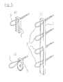
Für die Querkraftübertragung parallel zur Fuge sind verschiedene industriell gefertigte Verbindungselemente bekannt, wie sie schematisch in Fig. 5 dargestellt sind. Es gibt kontinuierliche Profilelemente (Fig. 5c)), wie beispielsweise die Pfeifer-VS®-Schiene, PFEIFER-VS®-Leiste, Betomax-Schlaufmax, Philipp-Schiene, und auch Einzelelemente (Fig. 5a), b)), die durch mehrfach wiederholte Anordnung von Bewehrungsschlaufen in der Fertigteilfuge übereinander die Querkraftübertragung sicherstellen sollen. Die Längen dieser Schienen und Leisten liegt aus logistischen Gründen bei etwa 1,20 m. Um Geschosshöhe zu erreichen, werden mehrere Schienenelemente nahtlos aneinandergefügt. Wenn weniger Schlaufen in einer Fuge benötig werden, so kommen einzelne Verwahrkästen mit je nur einer Schlaufen mit individuellem Abstand zum Einsatz. Beispielhaft können im Geschossbau oben zwei und unten zwei Einzelschlaufen benötigt werden.For the transverse force transmission parallel to the joint various industrially manufactured fasteners known, as shown schematically in Fig. 5. It There are continuous profile elements (Fig. 5c)), such as For example, the Pfeifer VS® rail, PFEIFER VS® rail, Betomax Schlaufmax, Philipp rail, and also individual elements (Fig. 5a), b)), which by repeatedly repeated arrangement of Reinforcement loops in the precast joint above each other To ensure lateral force transmission. The lengths of this Rails and rails are for logistical reasons about 1,20 m. To reach storey height, several will Rail elements seamlessly joined together. If less If loops are needed in a joint, then individual ones come Storage boxes with only one loops each with individual Distance to the insert. By way of example, in the storey building above two and below two individual loops are needed.
Als Einzelelemente stehen beispielsweise die Pfeifer-VS®-Box (Fig. 5a)) und die Philipp-Verbindungsschlaufe (Fig. 5b)) zur Verfügung. Beiden ist gemein, dass es sich um einen länglichen Verwahrkastenkastens handelt, an dessen einem Ende eine Seilschlaufe angeordnet ist, die im Inneren des Verwahrkastenkastens verwahrt werden kann. Die Gesamtlänge ist im Wesentlichen auf die eine Schlaufe abgestimmt und wesentlich kürzer als die Schienen und Leisten. Im Endzustand sind die Einzelboxen am Grund der Vergussnut angeordnet, und die einander gegenüberliegenden Schlaufen werden herausgeklappt und überlappend durch den eingebrachten und erhärtenden Mörtel verbunden.The individual elements are, for example, the Pfeifer VS® box (Figure 5a)) and the Philipp connection loop (Figure 5b)) Available. Both are mean that it is one elongated storage box, at one end a rope loop is arranged inside the Storage box can be kept. The total length is essentially tuned to the one loop and much shorter than the rails and bars. In the final state the individual boxes are arranged at the bottom of Vergussnut, and the opposite loops become unfolded and overlapped by the introduced and hardening mortar connected.
Bei den bekannten Verbindungselemententen hat sich jedoch gezeigt, dass insbesondere im Bereich von Einzelelementen und/oder freien Rändern eine frühzeitige Rissbildung im Beton bzw. Mörtel der Verbindung auftritt, wodurch die Tragfähigkeit, Steifigkeit und Dauerhaftigkeit der Verbindung beeinträchtigt wird. However, in the known Verbindungsentenenten has shown in particular in the range of individual elements and / or free edges early cracking in the concrete or mortar of the compound occurs, causing the Carrying capacity, rigidity and durability of the connection is impaired.
Es ist daher Aufgabe der vorliegenden Erfindung, ein Verbindungselement zum querkraftschlüssigen Verbinden von Betonfertigteilen bereitzustellen, das ein verbessertes Tragverhalten einer Verbindung bei Querkraftbeanspruchung ermöglicht.It is therefore an object of the present invention to provide a Connecting element for the transverse force-locking connection of To provide precast concrete, which is an improved Load-bearing behavior of a connection under shear stress allows.
Diese Aufgabe wird erfindungsgemäß durch ein
Verbindungselement mit den Merkmalen von Anspruch 1 gelöst.
Vorteilhafte Weiterbildungen der Erfindung sind in den
abhängigen Ansprüchen angegeben.This object is achieved by a
Connecting element solved with the features of
Der Erfindung liegt die Erkenntnis zugrunde, dass sich bei kompakten Verbindungselementen mit nur einer Bewehrungsschlaufe oder an freien Enden schienenartiger Verbindungselemente bei Querkraftbeanspruchung kein Kräftegleichgewicht einstellt, bei welchem die wesentlichen Zugkräfte in der Verbindung durch Bewehrungselemente aufgenommen werden.The invention is based on the finding that at compact connectors with only one Reinforcement bend or at rail ends at free ends Connecting elements with transverse force stress no Balance of forces sets, in which the essential Tensile forces in the connection through reinforcing elements be recorded.
Die Erfindung stellt daher darauf ab, das Verbindungselement insbesondere auch bei kompakten Abmessungen derart auszugestalten, dass die Zugkräfte, die in der Verbindung infolge einer schrägen Betondruckstrebe durch Querkraftbeanspruchung entstehen, durch Bewehrungselemente aufgenommen und weitergeleitet werden. Zu diesem Zweck ist erfindungsgemäß vorgesehen, dass bei einem gattungsgemäßen Verbindungselement die Durchdringungsöffnungen zweier Bewehrungsschlaufenelemente nahe gegenüberliegender Enden des Verwahrkastens vorgesehen sind. Mit anderen Worten liegen bei dem erfindungsgemäßen Verbindungselement zwei gegenüberliegende Bewehrungsschlaufen im herausgebogenen Zustand (Endzustand) nahe den jeweiligen Enden des Verwahrkastens. The invention therefore focuses on the connecting element especially in compact dimensions such To design that the tensile forces in the connection due to an oblique concrete strut by Transverse force stress caused by reinforcing elements be recorded and forwarded. For this purpose is According to the invention, that in a generic Connecting element, the penetration openings of two Reinforcement loop elements near opposite ends of the Deposit box are provided. In other words are included the connecting element according to the invention two opposite reinforcing loops in the bent out State (final state) near the respective ends of the Storage box.
Hierdurch ergibt sich bei jedem einzelnen, erfindungsgemäßen Verbindungselement ein in sich geschlossenes Tragverhalten, bei dem sich infolge Querkraftbeanspruchung eine geneigte Druckstrebe im Beton ausbilden kann, die sich an ihren (gedachten) Enden auf den Bewehrungsschlaufen des Verbindungselements abstützen kann, um das Einleiten übermäßiger Zugkräfte in den Beton bzw. Mörtel zu vermeiden. Auf diese Weise kann einer schädlichen Rissbildung im Verbindungsbereich wirksam vorgebeugt werden, was neben der Tragfähigkeit auch die Dauerhaftigkeit und Steifigkeit der Verbindung deutlich erhöht. Gleichzeitig besitzt das erfindungsgemäße Verbindungselement eine einfache Konstruktion und kann ohne Veränderung des bisherigen Bauablaufes problemlos eingesetzt werden.This results in each individual, invention Connecting element a self-contained load-bearing behavior, in which due to lateral force stress an inclined Pressure strut can form in the concrete, which adhere to her (imaginary) ends on the reinforcement loops of the Can support connecting element to initiate to avoid excessive tensile forces in the concrete or mortar. In this way, a harmful cracking in the Connection area can be effectively prevented, which in addition to the Viability also the durability and rigidity of the Compound significantly increased. At the same time it owns Connecting element according to the invention a simple Construction and can change without previous Construction process can be used easily.
Obgleich die vorliegende Erfindung nicht auf eine bestimmte Anzahl von Schlaufenelementen beschränkt ist, stellt ein Verbindungselement mit genau zwei Bewehrungsschlaufenelementen eine besonders bevorzugte Ausführungsform dar. Diese ist höchst variabel einsetzbar und besitzt im Unterschied zu bekannten Einzelelementen ein deutlich verbessertes, in sich geschlossenes Tragverhalten.Although the present invention is not limited to a particular Number of loop elements is limited Connecting element with exactly two Reinforcement loop elements a particularly preferred Embodiment is. This is highly variable and can be used has in contrast to known individual elements significantly improved, self-contained load-bearing behavior.
Gemäß einer Weiterbildung der vorliegenden Erfindung ist vorgesehen, dass der maximale Abstand der endnahen Durchdringungsöffnungen von einem Ende in Längsrichtung des Verwahrkastens geringer ist als das 0,5-fache einer Schlaufenlänge, um welche die Bewehrungsschlaufenelemente im herausgebogenen Zustand von dem Verwahrkasten hervorstehen. Hierdurch wird ein besonders kompaktes Verbindungselement bereitgestellt. Darüber hinaus kann sich eine infolge von Querkraftbeanspruchung ausbildende Betondruckstrebe bei randnaher Anordnung der Durchdringungsöffnungen und somit der eingebauten Bewehrungsschlaufenelemente wirksam an den nahegelegenen Enden des Verwahrkastens abstützen, wodurch das Tragverhalten des Verbindungselements weiter verbessert wird. Dabei ist es bevorzugt, dass der maximale Abstand der endnahen Durchdringungsöffnungen von einem Ende in Längsrichtung des Verwahrkastens geringer ist als das 0,25fache, besonders bevorzugt das 0,1-fache der Schlaufenlänge.According to one embodiment of the present invention provided that the maximum distance of near-end Penetration openings from one end in the longitudinal direction of Storage box is less than 0.5 times one Loop length around which the reinforcement loop elements in the bent out state of the storage box protruding. This will be a particularly compact connection element provided. In addition, a result of Transverse force stress forming concrete strut at near-edge arrangement of the penetration openings and thus the Built-in reinforcing loop elements effectively to the supporting nearby ends of the storage box, whereby the Tragverhalten of the connecting element is further improved. It is preferred that the maximum distance of the near-penetration openings from one end into Longitudinal direction of the storage box is less than 0.25 times, more preferably 0.1 times the loop length.
Hinsichtlich kompakter Liefer- und Einbauabmessungen des erfindungsgemäßen Verbindungselements ist gemäß einer Weiterbildung vorgesehen, dass die Länge des Verwahrkastens geringer ist als das 2,5-fache einer Schlaufenlänge, um welche die Bewehrungsschlaufenelemente im herausgebogenen Zustand von dem Verwahrkasten hervorstehen. Gleichzeitig stellt diese Konfiguration jedoch auch sicher, dass die Bewehrungsschlaufenelemente im eingebauten Zustand ausreichend nahe beieinander liegen, sodass die Neigung einer sich zwischen den Bewehrungsschlaufenelementen einstellenden Druckstrebe nicht zu gering wird und die auftretenden Druckkräfte daher nicht übermäßig groß werden. Ein noch kompakteres Verbindungselement wird erfindungsgemäß erhalten, wenn die Länge des Verwahrkastens geringer ist als das 1,5fache der Schlaufenlänge.Regarding compact delivery and installation dimensions of the The connecting element according to the invention is according to a Continuing provided that the length of the custody box less than 2.5 times a loop length to which bent out the reinforcement loop elements in the Condition of the storage box protrude. simultaneously However, this configuration also ensures that the Reinforcement loop elements in installed condition sufficiently close to each other, so that the tendency of a arising between the reinforcing loop elements Strut is not too low and the occurring Compressive forces therefore do not become excessively large. One more more compact connecting element is obtained according to the invention, if the length of the storage box is less than 1.5 times the loop length.
Gemäß einer Weiterbildung der Erfindung ist ferner vorgesehen, dass zumindest zwei Bewehrungsschlaufenelemente im in den Verwahrkasten aufgenommenen Zustand einander zugewandt sind und bevorzugt einander zumindest teilweise überlappen, sodass das erfindungsgemäße Verbindungselement kaum größere Abmessungen besitzt als ein bekanntes Einzelschlaufenelement, jedoch ein drastisch verbessertes Tragverhalten aufweist.According to a development of the invention is further provided that at least two reinforcement loop elements in the recorded in the storage box state each other are facing and preferably at least partially overlap, so that the connecting element according to the invention hardly larger dimensions than a known one Single loop element, but a dramatically improved Has carrying behavior.
Um eine wirksame Aufnahme und Weiterleitung der infolge einer Querkraftbeanspruchung auftretenden Kräfte im Beton sicherzustellen, ist gemäß einer Weiterbildung der vorliegenden Erfindung vorgesehen, dass der Verwahrkastenboden zumindest abschnittsweise durch Erhebungen und/oder Vertiefungen profiliert ist. Hierdurch wird sichergestellt, dass die Bewehrungsschlaufenelemente des Verbindungselements bei Querkraftbeanspruchung auch aktiviert werden, bevor sich eine übermäßige Verformung und Rissbildung im Bereich der Verbindung einstellt. Dabei ist es besonders bevorzugt, dass die Erhebungen und/oder Vertiefungen benachbart zu den Durchdringungsöffnungen vorgesehen sind, sodass sich das gewünschte, geschlossene Tragsystem unter Einbindung der Bewehrungsschlaufenelemente einstellt.In order to ensure effective reception and transmission as a result of Transverse force stress occurring forces in concrete To ensure, according to a further development of Present invention provides that the Trunk floor at least in sections by surveys and / or depressions is profiled. This will ensured that the reinforcement loop elements of the Connecting element also activated in case of transverse force stress Becoming an excessive deformation and cracking in the area of the connection. It is special preferred that the elevations and / or depressions are provided adjacent to the penetration openings, so that the desired, closed support system under Integration of the reinforcement loop elements sets.
Das erfindungsgemäße Verbindungselement kann einzeln oder in Kombination mit gleichartigen oder andersartigen Verbindungselementen eingesetzt werden. Auf diese Weise wird durch eine lokal begrenzte Maßnahme das Tragverhalten der Gesamtverbindung vorteilhaft beeinflusst.The connecting element according to the invention can be used individually or in Combination with similar or different Connecting elements are used. This way will by a locally limited measure the carrying behavior of the Overall connection favorably influenced.
- Fig. 1aFig. 1a
- zeigt schematisch eine Perspektivansicht einer ersten Ausführungsform des erfindungsgemäßen Verbindungselements;schematically shows a perspective view of a first embodiment of the invention Connector;
- Fig. 1bFig. 1b
- zeigt schematisch eine Perspektivansicht einer zweiten Ausführungsform des erfindungsgemäßen Verbindungselements;schematically shows a perspective view of a second embodiment of the invention Connector;
- Fig. 2Fig. 2
- zeigt schematisch eine Perspektivansicht einer dritten Ausführungsform des erfindungsgemäßen Verbindungselements;schematically shows a perspective view of a third embodiment of the invention Connector;
- Fig. 3Fig. 3
- zeigt schematisch eine Modellvorstellung des Tragverhaltens zweier miteinander durch Verbindungselemente verbundener Betonfertigteile;schematically shows a model concept of the Carrying behavior of two together Connecting elements of connected precast concrete elements;
- Fig. 4Fig. 4
- zeigt schematisch eine querkraftschlüssige Verbindung von Betonfertigteilen unter Einsatz des erfindungsgemäßen Verbindungselements;schematically shows a transverse force-locking Connection of precast concrete parts using the connecting element according to the invention;
- Fig. 5Fig. 5
- zeigt schematisch Verbindungselemente gemäß dem Stand der Technik.schematically shows connecting elements according to the State of the art.
Bevorzugte Ausführungsformen der Erfindung werden nachfolgend ausführlich unter Bezugnahme auf die begleitenden Zeichnungen beschrieben.Preferred embodiments of the invention are hereafter in detail with reference to the accompanying drawings described.
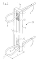
Fig. 1a zeigt schematisch ein Verbindungselement 20 gemäß
einer ersten Ausführungsform der vorliegenden Erfindung. Das
Verbindungselement 20 dient zum querkraftschlüssigen
Verbinden von Betonfertigteilen an einer Fuge mit Querkräften
parallel zur Fugenlängsrichtung und umfasst einen
Verwahrkasten 1 sowie zwei herausbiegbare
Bewehrungsschlaufenelemente 3. Der Verwahrkasten 1 besitzt
eine längliche, hohlkastenartige Form mit einer Länge L und
zwei längsstirnseitigen Enden 1a, 1b. In einem
Verwahrkastenboden 1c sind zwei Öffnungen 1', 1'' vorgesehen,
an welchen die Bewehrungsschlaufenelemente 3 den
Verwahrkasten 1 durchdringen.Fig. 1a shows schematically a connecting
Bei den Bewehrungsschlaufenelementen 3 kann es sich
beispielsweise um Betonstabstahl oder um flexible
Seilelemente handeln, die an ihren freien Enden über eine
Klemme 2, Muffe oder dergleichen verbunden sind.The
Die Durchdringungsöffnungen 1', 1'' sind erfindungsgemäß nahe
den gegenüberliegenden Enden 1a, 1b des Verwahrkastens 1
vorgesehen, wie in Fig. 1a gezeigt. Dabei ist es bevorzugt,
dass der in Fig. 1a gezeigte, maximale Abstand a der
Durchdringungsöffnungen 1', 1'' von den Enden 1a, 1b des
Verwahrkastens 1 geringer ist als das 0,5-fache der
untenstehend noch näher definierten Schlaufenlänge 1. Darüber
hinaus ist der maximale Abstand a der Durchdringungsöffnungen
1', 1'' von den Enden 1a, 1b des Verwahrkastens 1 zumindest
bei kompakten Verbindungselementen bevorzugt geringer als das
0,1-fache der Länge L des Verwahrkastens. The penetration openings 1 ', 1' 'are close to the invention
the opposite ends 1a, 1b of the storage box. 1
provided, as shown in Fig. 1a. It is preferred
that shown in Fig. 1a, the maximum distance a of
Penetration openings 1 ', 1' 'from the
Ferner ist die Länge L des Verwahrkastens derart ausgelegt,
dass die Bewehrungsschlaufen 3 problemlos im Inneren des
Verwahrkastens 1 aufgenommen werden können, wie in Fig. 1a
gezeigt. Dabei sind die Schlaufen 3 im Unterschied zum Stand
der Technik einander zugewandt. Ausgehend von diesem Zustand
können die Schlaufen 3 aus dem Verwahrkasten 1 herausgebogen
werden, um den in Fig. 2 gezeigten Endzustand zu erreichen,
in welchem die Schlaufen 3 um eine Schlaufenlänge 1 von dem
Verwahrkasten 1 hervorstehen. In der in Fig. 1a gezeigten
Ausführungsform ist die Länge L des Verwahrkastens 1 etwas
geringer als das 2,5-fache der Schlaufenlänge 1.Furthermore, the length L of the storage box is designed such that
that the
Fig. 1b zeigt ein Verbindungselement 20 gemäß einer zweiten
bevorzugten Ausführungsform der Erfindung. Das in Fig. 1b
gezeigte Verbindungselement 20 unterscheidet sich von
demjenigen gemäß der in Fig. 1a gezeigten, ersten
Ausführungsform in der Länge L des Verwahrkastens 1. Diese
ist bei der in Fig. 1b gezeigten, zweiten Ausführungsform
erheblich geringer und beträgt etwas weniger als das 1,5-fache
der Schlaufenlänge 1. Hierdurch ergibt sich ein noch
kompakteres Verbindungselement, in welchem die Schlaufen 3 im
eingeklappten Zustand überlappend angeordnet sind.
Gleichzeitig ist der maximale Abstand a der
Durchdringungsöffnungen 1', 1'' in der zweiten
Ausführungsform absolut gesehen etwa genauso groß wie in der
ersten Ausführungsform, wodurch sich jedoch ein etwas
größeres Verhältnis zwischen maximalem Abstand a und Länge L
des Verwahrkastens ergibt.Fig. 1b shows a connecting
Eine dritte bevorzugte Ausführungsform des erfindungsgemäßen
Verbindungselements 20 ist in Fig. 2 schematisch in einer
Perspektivansicht dargestellt. Diese unterscheidet sich von
der in Fig. 1a gezeigten, ersten Ausführungsform durch
Profilierungen, die in der Form von Vertiefungen 12 im
Verwahrkastenboden 1c vorgesehen sind. Dabei sind die
Vertiefungen 12 in der vorliegenden Ausführungsform
benachbart zu den Durchdringungsöffnungen 1', 1'' vorgesehen. A third preferred embodiment of the
Ferner zeigt Fig. 2 das Verbindungselement 20 mit um die
Länge 1 herausgebogenen Bewehrungsschlaufenelementen 3, d.h.
in dem Endzustand, welchen das Verbindungselement in einer
Verbindung von Betonfertigteilen einnimmt. Als Bezugspunkt
für die Schlaufenlänge 1 dient hierbei, wie in Fig. 2
gezeigt, der Verwahrkastenboden 1c.Furthermore, Fig. 2 shows the connecting
Eine Verbindung von Betonfertigteilen unter Einsatz des
erfindungsgemäßen Verbindungselements 20 ist schematisch in
Fig. 4 dargestellt, die sowohl eine vertikale als auch eine
horizontale Schnittansicht der Verbindung zeigt. Wie
insbesondere in der unten dargestellten, horizontalen
Schnittansicht zu erkennen ist, sind die erfindungsgemäßen
Verbindungselemente 20 in stirnseitigen Vergussnuten 11 von
miteinander zu verbindenden Betonfertigteilen 5 vorgesehen.
Die Betonfertigteile 5 sind mit ihren Stirnseiten derart
nebeneinander gestellt, dass sich im Bereich der Vergussnuten
11 eine Fuge 10 bildet, die später mit Vergussmörtel gefüllt
wird. Nach dem Nebeneinanderstellen der Betonfertigteile 5
werden die Bewehrungsschlaufenelemente 3 aus den
Verwahrkästen 1 herausgebogen, sodass sich die
Bewehrungsschlaufenelemente 3 einander gegenüberliegender
Verbindungselemente 20 überlappen. Anschließend wird ein
Montagestab 8 aus Betonstahl durch die Überlappungen geführt.
Abschließend wird der Verguss der Fuge vorgenommen, um die
Fertigteile 5 kraftschlüssig miteinander zu verbinden. Dabei
sind die Verbindungselemente 20, wie im oberen Teil von Fig.
4 in dem Vertikalschnitt zu erkennen ist, bevorzugt
gleichmäßig über die Betonfertigteile 5 angeordnet.A combination of precast concrete elements using the
connecting
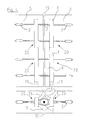
Ein Modell für das sich im Bereich zweier miteinander durch
Verbindungselemente 20 verbundener Betonfertigteile 5
einstellende Tragverhalten ist schematisch in Fig. 3
dargestellt. Bei Vorliegen einer Querkraftbeanspruchung Q,
deren Wirkrichtung schematisch durch Pfeile 6 in Fig. 3
angegeben ist, bildet sich zwischen den Betonfertigteilen 5
im Vergussmörtel bzw. Beton ein Druckfeld aus, das durch eine
geneigte Betondruckstrebe 7 modelliert werden kann. Die
modellhafte, geneigte Betondruckstrebe 7 stützt sich an ihren
Enden auf den Verwahrkästen 1 der Verbindungselemente 20 ab,
wobei sowohl die Verwahrkastenenden 1a, 1b als auch die
Vertiefungen 12 des Verwahrkastenbodens 1c zu einer
verbesserten Abstützung und Lastabtragung der Druckstrebe 7
beitragen. Um ein Kräftegleichgewicht zu erzielen, müssen die
von der Druckstrebe 7 geweckten Kräfte 5 unten und oben
aufgenommen werden. Dies erfolgt in dem Modell durch die an
den Verwahrkastenenden angeordneten
Bewehrungsschlaufenelemente 3, in denen sich horizontale
Zugstreben 4 bilden. Ein derartiges Gleichgewicht ohne
erhebliche Zugbeanspruchung des Betons kann sich bei Einsatz
des erfindungsgemäßen Verbindungselements 20 durch die
vorteilhafte Anordnung der Bewehrungsschlaufenelemente 3
einstellen, was bei bekannten Einzelschlaufenelementen bisher
nicht möglich gewesen ist. Daher wird durch den Einsatz des
erfindungsgemäßen Verbindungselements 20 die Entstehung von
Schädigungen und Rissen im Mörtel bzw. Beton verhindert und
somit die Tragfähigkeit, Steifigkeit und Dauerhaftigkeit der
Verbindung beträchtlich erhöht.A model for working in the field of two together
Connecting
Die vorstehend beschriebenen, bevorzugten Ausführungsformen weisen jeweils genau zwei Bewehrungsschlaufenelemente auf, da sich hierdurch besonders kompakte und vielseitige Verbindungselemente mit einem in sich geschlossenen Tragverhalten ergeben. Im Rahmen der vorliegenden Erfindung ist es jedoch ebenso möglich, die Verbindungselemente mit einer größeren Anzahl von Bewehrungsschlaufenelemente, sofern zumindest die zwei äußersten Bewehrungsschlaufenelemente nahe den Enden des Verwahrkastens angeordnet sind. The preferred embodiments described above each have exactly two reinforcing loop elements, since This makes it particularly compact and versatile Connecting elements with a self-contained Tragverhalten arise. In the context of the present invention However, it is also possible, the fasteners with a larger number of reinforcing loop elements, if at least the two outermost reinforcing loop elements close the ends of the storage box are arranged.
- 11
- Verwahrkasten für die BewehrungsschlaufenDeposit box for the reinforcement loops
- 1a, b1a, b
- VerwahrkastenendenVerwahrkastenenden
- 1c1c
- Verwahrkastenbodenstorage box
- 1', 1''1 ', 1' '
- Durchdringungsöffnungenpenetration holes
- 22
- Endverankerung der BewehrungsschlaufeEnd anchorage of the reinforcement loop
- 33
- Bewehrungsschlaufe aus Drahtseil oder BetonstahlReinforcement loop made of wire rope or reinforcing steel
- 44
- Horizontale ZugkraftHorizontal traction
- 55
- Betonfertigteil wand- oder stützenartigPrecast concrete wall or pedestal
- 66
- Querkraft parallel zur WandfugeTransverse force parallel to the wall joint
- 77
- Schräge Druckstrebe im VergussbereichOblique pressure strut in the casting area
- 88th
- Montagestab aus BetonstahlAssembling rod made of reinforcing steel
- 99
- Bereich mit VergussmörtelArea with grout
- 1010
- Fuge zwischen zwei BetonfertigteilenJoint between two precast concrete elements
- 1111
- Vergussnutgrouting groove
- 1212
- Vertiefungen oder Erhebungen zur Verbesserung des DruckstrebenangriffsDeepening or surveys to improve the Struts attack
- 2020
- Verbindungselementconnecting element
- LL
- Länge des VerwahrkastensLength of the storage box
- ll
- Schlaufenlängestrap
Claims (9)
dadurch gekennzeichnet, dass
die Durchdringungsöffnungen (1', 1'') zweier Bewehrungsschlaufenelemente (3) nahe gegenüberliegender Enden (1a, 1b) des Verwahrkastens (1) vorgesehen sind.Connecting element (20) for the transverse force-locking connection of precast concrete parts (5) to a joint (10) with transverse forces parallel to the longitudinal direction joint, comprising a preferably elongated storage box (1) and at least two reinforcing loop elements (3) in the storage box (1) and receivable can be bent out, wherein the reinforcement loop elements (3) penetrate the storage box (1) in the region of a respective penetration opening (1 ', 1'') of the storage box (1),
characterized in that
the penetrating openings (1 ', 1'') of two reinforcing loop elements (3) are provided near opposite ends (1a, 1b) of the storage box (1).
Priority Applications (4)
| Application Number | Priority Date | Filing Date | Title |
|---|---|---|---|
| EP09153597A EP2055846B1 (en) | 2004-02-11 | 2005-02-10 | Use of elements for connecting prefinished concrete elements |
| PL09153597T PL2055846T3 (en) | 2004-02-11 | 2005-02-10 | Use of elements for connecting prefinished concrete elements |
| DK09153597.1T DK2055846T3 (en) | 2004-02-11 | 2005-02-10 | Use of Connecting Elements to Connect Prefabricated Concrete Elements |
| PL05002768T PL1589156T3 (en) | 2004-02-11 | 2005-02-10 | Element for connecting prefinished concrete elements |
Applications Claiming Priority (2)
| Application Number | Priority Date | Filing Date | Title |
|---|---|---|---|
| DE202004002110U DE202004002110U1 (en) | 2004-02-11 | 2004-02-11 | Connecting element for connecting precast concrete elements |
| DE202004002110U | 2004-02-11 |
Related Child Applications (1)
| Application Number | Title | Priority Date | Filing Date |
|---|---|---|---|
| EP09153597A Division EP2055846B1 (en) | 2004-02-11 | 2005-02-10 | Use of elements for connecting prefinished concrete elements |
Publications (3)
| Publication Number | Publication Date |
|---|---|
| EP1589156A2 true EP1589156A2 (en) | 2005-10-26 |
| EP1589156A3 EP1589156A3 (en) | 2008-05-21 |
| EP1589156B1 EP1589156B1 (en) | 2009-05-27 |
Family
ID=34716806
Family Applications (2)
| Application Number | Title | Priority Date | Filing Date |
|---|---|---|---|
| EP05002768A Active EP1589156B1 (en) | 2004-02-11 | 2005-02-10 | Element for connecting prefinished concrete elements |
| EP09153597A Active EP2055846B1 (en) | 2004-02-11 | 2005-02-10 | Use of elements for connecting prefinished concrete elements |
Family Applications After (1)
| Application Number | Title | Priority Date | Filing Date |
|---|---|---|---|
| EP09153597A Active EP2055846B1 (en) | 2004-02-11 | 2005-02-10 | Use of elements for connecting prefinished concrete elements |
Country Status (6)
| Country | Link |
|---|---|
| EP (2) | EP1589156B1 (en) |
| AT (1) | ATE432393T1 (en) |
| DE (2) | DE202004002110U1 (en) |
| DK (2) | DK1589156T3 (en) |
| ES (2) | ES2396476T3 (en) |
| PL (2) | PL1589156T3 (en) |
Cited By (3)
| Publication number | Priority date | Publication date | Assignee | Title |
|---|---|---|---|---|
| DE202009000910U1 (en) | 2009-01-23 | 2010-06-17 | Philipp Gmbh | Device for holding rope loops |
| CN110185155A (en) * | 2019-06-25 | 2019-08-30 | 中国建筑标准设计研究院有限公司 | The seam connector and dry wall system and its construction method of a kind of prefabricated components |
| EP3879045A1 (en) | 2020-03-11 | 2021-09-15 | Pfeifer Holding GmbH & Co. KG | Connecting element for the non-positive connection of concrete components |
Families Citing this family (5)
| Publication number | Priority date | Publication date | Assignee | Title |
|---|---|---|---|---|
| DE102008013206B4 (en) * | 2008-03-07 | 2019-12-05 | P & T Technische Mörtel GmbH & Co. KG | Method for joining precast concrete parts and construction made therewith |
| DE102008063525B4 (en) * | 2008-12-18 | 2017-03-09 | P & T Technische Mörtel GmbH & Co. KG | Method and device for connecting precast concrete elements |
| DE102010003272A1 (en) | 2010-03-25 | 2011-09-29 | Georg Weidner | Device for producing connection between precast concrete parts, has reinforcement part arranged in groove such that anchor region is extended outside support part on bottom side and connecting portion is inserted into groove |
| DE202010010127U1 (en) | 2010-07-12 | 2011-10-24 | Pfeifer Seil- Und Hebetechnik Gmbh | Deposit box and use of a deposit box |
| RU2499103C1 (en) * | 2012-05-05 | 2013-11-20 | Открытое акционерное общество Центральный научно-исследовательский и проектный институт жилых и общественных зданий (ОАО "ЦНИИЭП жилища") | Method for manufacturing of cast in place and precast node of pillar connection with crossbar |
Citations (1)
| Publication number | Priority date | Publication date | Assignee | Title |
|---|---|---|---|---|
| US6308478B1 (en) | 1997-07-03 | 2001-10-30 | Pfeifer Holding Gmbh & Co. Kg | Device for connecting reinforced concrete sections |
Family Cites Families (9)
| Publication number | Priority date | Publication date | Assignee | Title |
|---|---|---|---|---|
| ATE21951T1 (en) * | 1982-09-10 | 1986-09-15 | Pebea Nv | REINFORCEMENT HOLDER FOR USE IN CONCRETING CONCRETE AND METHOD OF MAKING THE SAME. |
| DE8336278U1 (en) | 1983-12-17 | 1984-03-29 | Hoff, Walter, 4000 Düsseldorf | REINFORCEMENT ELEMENT |
| FR2710091A1 (en) * | 1993-09-16 | 1995-03-24 | Sauveplane Pierre | Device for placing and positioning reinforcement bars in formwork (shuttering) for reinforced concrete |
| DE9407998U1 (en) * | 1994-05-13 | 1994-07-14 | Dausend Hans Werner | Storage box for connection reinforcement bars |
| DE29612573U1 (en) * | 1996-07-20 | 1997-11-20 | Pfeifer Seil Hebetech | Device for joining precast concrete parts |
| DE29711542U1 (en) * | 1997-07-03 | 1998-10-29 | Pfeifer Seil Hebetech | Device for connecting reinforced concrete parts |
| DE29906417U1 (en) * | 1999-04-12 | 2000-09-14 | Reus Gmbh & Co Kg | Device for storing at least one elastically deformable rope loop in the surface of precast concrete parts |
| DE20111702U1 (en) * | 2001-07-18 | 2002-11-21 | Pfeifer Holding Gmbh & Co Kg | Device for joining precast concrete parts |
| DE20319471U1 (en) * | 2003-12-16 | 2005-01-20 | Pfeifer Holding Gmbh & Co. Kg | Joint for prefabricated concrete sections has grooves in joint faces to receive connectors armatures with wire loops to receive tension forces |
-
2004
- 2004-02-11 DE DE202004002110U patent/DE202004002110U1/en not_active Expired - Lifetime
-
2005
- 2005-02-10 AT AT05002768T patent/ATE432393T1/en active
- 2005-02-10 ES ES09153597T patent/ES2396476T3/en active Active
- 2005-02-10 PL PL05002768T patent/PL1589156T3/en unknown
- 2005-02-10 DE DE502005007331T patent/DE502005007331D1/en active Active
- 2005-02-10 ES ES05002768T patent/ES2327047T3/en active Active
- 2005-02-10 PL PL09153597T patent/PL2055846T3/en unknown
- 2005-02-10 DK DK05002768T patent/DK1589156T3/en active
- 2005-02-10 EP EP05002768A patent/EP1589156B1/en active Active
- 2005-02-10 DK DK09153597.1T patent/DK2055846T3/en active
- 2005-02-10 EP EP09153597A patent/EP2055846B1/en active Active
Patent Citations (1)
| Publication number | Priority date | Publication date | Assignee | Title |
|---|---|---|---|---|
| US6308478B1 (en) | 1997-07-03 | 2001-10-30 | Pfeifer Holding Gmbh & Co. Kg | Device for connecting reinforced concrete sections |
Cited By (5)
| Publication number | Priority date | Publication date | Assignee | Title |
|---|---|---|---|---|
| DE202009000910U1 (en) | 2009-01-23 | 2010-06-17 | Philipp Gmbh | Device for holding rope loops |
| CN110185155A (en) * | 2019-06-25 | 2019-08-30 | 中国建筑标准设计研究院有限公司 | The seam connector and dry wall system and its construction method of a kind of prefabricated components |
| CN110185155B (en) * | 2019-06-25 | 2024-03-15 | 中国建筑标准设计研究院有限公司 | Joint connector of prefabricated part, prefabricated wall system and construction method of prefabricated wall system |
| EP3879045A1 (en) | 2020-03-11 | 2021-09-15 | Pfeifer Holding GmbH & Co. KG | Connecting element for the non-positive connection of concrete components |
| DE102020203108A1 (en) | 2020-03-11 | 2021-09-16 | Pfeifer Holding Gmbh & Co. Kg | Connection element for frictional connection of concrete components |
Also Published As
| Publication number | Publication date |
|---|---|
| DK1589156T3 (en) | 2009-09-07 |
| ES2327047T3 (en) | 2009-10-23 |
| PL2055846T3 (en) | 2013-03-29 |
| ATE432393T1 (en) | 2009-06-15 |
| EP2055846A1 (en) | 2009-05-06 |
| PL1589156T3 (en) | 2009-10-30 |
| EP2055846B1 (en) | 2012-10-10 |
| ES2396476T3 (en) | 2013-02-21 |
| EP1589156A3 (en) | 2008-05-21 |
| EP1589156B1 (en) | 2009-05-27 |
| DE202004002110U1 (en) | 2005-06-30 |
| DE502005007331D1 (en) | 2009-07-09 |
| DK2055846T3 (en) | 2013-01-07 |
Similar Documents
| Publication | Publication Date | Title |
|---|---|---|
| AT404273B (en) | SHUTTERING WITH A VARIETY OF CONNECTABLE LIGHTWEIGHT SHUTTERING ELEMENTS | |
| DE60318634T2 (en) | FORMWORK WITH INCREASED RESISTANCE FOR CONCRETE WALL | |
| EP1589156B1 (en) | Element for connecting prefinished concrete elements | |
| DE202005010080U1 (en) | Connector for connecting concrete parts with transverse strength has floor profiled with groups of projections and recesses alternating in longitudinal direction, whereby each group has at least one projection and/or at least one recess | |
| EP0658660B1 (en) | Heat insulation structural member | |
| EP3183401B1 (en) | Concrete construction of modular design | |
| DE102010054364B4 (en) | Method for building a gabion wall | |
| DE1811932A1 (en) | Concrete beams, especially for grids and retaining walls | |
| DE3912710C2 (en) | Support structure to secure a backfill | |
| CH707356A2 (en) | Precast concrete to create a protective wall. | |
| EP3073020A1 (en) | Building kit for constructing a building wall | |
| DE3432940A1 (en) | Prefabricated masonry structure | |
| EP3346058A1 (en) | Gabion wall module and method for producing a gabion wall with at least one gabion wall module | |
| DE2937478A1 (en) | COMPONENT KIT AND COMPONENT FOR THE PRODUCTION OF CONSTRUCTIONS AND THE WALL MADE THEREOF AND USE FOR THE WALL PRODUCTION | |
| DE19835900C2 (en) | Prefabricated concrete components and buildings constructed using precast concrete component groups | |
| EP3492665A1 (en) | Finished concrete part with at least one load-absorbing component and connection plate for assembly in the gap between same and load-absorbing component | |
| EP0645501B1 (en) | Method for the production of prefabricated moduls for the construction of buildings and prefabricated modul | |
| DE3632703A1 (en) | Joint-shuttering element | |
| DE1784137A1 (en) | Production of walls made of concrete or reinforced concrete underground | |
| EP3798377B1 (en) | Method for producing a structure | |
| DE102017211092A1 (en) | Tower and method of manufacture | |
| DE19636828C2 (en) | Method and component for the production of structural parts | |
| DE854838C (en) | Method and stone molds for the production of rising steel-reinforced masonry, such. B. for columns, pillars and walls as well as chimneys, silos, containers and other heavily used components | |
| DE202013011136U1 (en) | Prefabricated concrete element for creating a protective wall | |
| EP3995644A1 (en) | Facade cladding gabion structure |
Legal Events
| Date | Code | Title | Description |
|---|---|---|---|
| PUAI | Public reference made under article 153(3) epc to a published international application that has entered the european phase |
Free format text: ORIGINAL CODE: 0009012 |
|
| AK | Designated contracting states |
Kind code of ref document: A2 Designated state(s): AT BE BG CH CY CZ DE DK EE ES FI FR GB GR HU IE IS IT LI LT LU MC NL PL PT RO SE SI SK TR |
|
| AX | Request for extension of the european patent |
Extension state: AL BA HR LV MK YU |
|
| RIC1 | Information provided on ipc code assigned before grant |
Ipc: 7E 04B 1/61 B Ipc: 7E 04B 1/41 A |
|
| PUAL | Search report despatched |
Free format text: ORIGINAL CODE: 0009013 |
|
| AK | Designated contracting states |
Kind code of ref document: A3 Designated state(s): AT BE BG CH CY CZ DE DK EE ES FI FR GB GR HU IE IS IT LI LT LU MC NL PL PT RO SE SI SK TR |
|
| AX | Request for extension of the european patent |
Extension state: AL BA HR LV MK YU |
|
| GBC | Gb: translation of claims filed (gb section 78(7)/1977) | ||
| 17P | Request for examination filed |
Effective date: 20080826 |
|
| GRAP | Despatch of communication of intention to grant a patent |
Free format text: ORIGINAL CODE: EPIDOSNIGR1 |
|
| AKX | Designation fees paid |
Designated state(s): AT BE BG CH CY CZ DE DK EE ES FI FR GB GR HU IE IS IT LI LT LU MC NL PL PT RO SE SI SK TR |
|
| GRAS | Grant fee paid |
Free format text: ORIGINAL CODE: EPIDOSNIGR3 |
|
| GRAA | (expected) grant |
Free format text: ORIGINAL CODE: 0009210 |
|
| AK | Designated contracting states |
Kind code of ref document: B1 Designated state(s): AT BE BG CH CY CZ DE DK EE ES FI FR GB GR HU IE IS IT LI LT LU MC NL PL PT RO SE SI SK TR |
|
| REG | Reference to a national code |
Ref country code: GB Ref legal event code: FG4D Free format text: NOT ENGLISH |
|
| REG | Reference to a national code |
Ref country code: CH Ref legal event code: NV Representative=s name: NOVAGRAAF INTERNATIONAL SA Ref country code: CH Ref legal event code: EP |
|
| REG | Reference to a national code |
Ref country code: RO Ref legal event code: EPE |
|
| PLBI | Opposition filed |
Free format text: ORIGINAL CODE: 0009260 |
|
| REG | Reference to a national code |
Ref country code: IE Ref legal event code: FG4D Free format text: LANGUAGE OF EP DOCUMENT: GERMAN |
|
| REF | Corresponds to: |
Ref document number: 502005007331 Country of ref document: DE Date of ref document: 20090709 Kind code of ref document: P |
|
| REG | Reference to a national code |
Ref country code: SE Ref legal event code: TRGR |
|
| 26 | Opposition filed |
Opponent name: HALFEN GMBH Effective date: 20090602 |
|
| NLR1 | Nl: opposition has been filed with the epo |
Opponent name: HALFEN GMBH |
|
| REG | Reference to a national code |
Ref country code: DK Ref legal event code: T3 |
|
| REG | Reference to a national code |
Ref country code: ES Ref legal event code: FG2A Ref document number: 2327047 Country of ref document: ES Kind code of ref document: T3 |
|
| PG25 | Lapsed in a contracting state [announced via postgrant information from national office to epo] |
Ref country code: PT Free format text: LAPSE BECAUSE OF FAILURE TO SUBMIT A TRANSLATION OF THE DESCRIPTION OR TO PAY THE FEE WITHIN THE PRESCRIBED TIME-LIMIT Effective date: 20090927 |
|
| REG | Reference to a national code |
Ref country code: PL Ref legal event code: T3 |
|
| PG25 | Lapsed in a contracting state [announced via postgrant information from national office to epo] |
Ref country code: SI Free format text: LAPSE BECAUSE OF FAILURE TO SUBMIT A TRANSLATION OF THE DESCRIPTION OR TO PAY THE FEE WITHIN THE PRESCRIBED TIME-LIMIT Effective date: 20090527 |
|
| REG | Reference to a national code |
Ref country code: HU Ref legal event code: AG4A Ref document number: E006666 Country of ref document: HU |
|
| PG25 | Lapsed in a contracting state [announced via postgrant information from national office to epo] |
Ref country code: BG Free format text: LAPSE BECAUSE OF FAILURE TO SUBMIT A TRANSLATION OF THE DESCRIPTION OR TO PAY THE FEE WITHIN THE PRESCRIBED TIME-LIMIT Effective date: 20090827 |
|
| PLAX | Notice of opposition and request to file observation + time limit sent |
Free format text: ORIGINAL CODE: EPIDOSNOBS2 |
|
| PLBB | Reply of patent proprietor to notice(s) of opposition received |
Free format text: ORIGINAL CODE: EPIDOSNOBS3 |
|
| PG25 | Lapsed in a contracting state [announced via postgrant information from national office to epo] |
Ref country code: MC Free format text: LAPSE BECAUSE OF NON-PAYMENT OF DUE FEES Effective date: 20100301 Ref country code: GR Free format text: LAPSE BECAUSE OF FAILURE TO SUBMIT A TRANSLATION OF THE DESCRIPTION OR TO PAY THE FEE WITHIN THE PRESCRIBED TIME-LIMIT Effective date: 20090828 |
|
| PG25 | Lapsed in a contracting state [announced via postgrant information from national office to epo] |
Ref country code: IT Free format text: LAPSE BECAUSE OF NON-PAYMENT OF DUE FEES Effective date: 20100210 |
|
| REG | Reference to a national code |
Ref country code: CH Ref legal event code: PFA Owner name: PFEIFER HOLDING GMBH & CO. KG Free format text: PFEIFER HOLDING GMBH & CO. KG#DR.-KARL-LENZ-STRASSE 66#87700 MEMMINGEN (DE) -TRANSFER TO- PFEIFER HOLDING GMBH & CO. KG#DR.-KARL-LENZ-STRASSE 66#87700 MEMMINGEN (DE) |
|
| PGRI | Patent reinstated in contracting state [announced from national office to epo] |
Ref country code: IT Effective date: 20110616 |
|
| PLCK | Communication despatched that opposition was rejected |
Free format text: ORIGINAL CODE: EPIDOSNREJ1 |
|
| APAH | Appeal reference modified |
Free format text: ORIGINAL CODE: EPIDOSCREFNO |
|
| APBM | Appeal reference recorded |
Free format text: ORIGINAL CODE: EPIDOSNREFNO |
|
| APBP | Date of receipt of notice of appeal recorded |
Free format text: ORIGINAL CODE: EPIDOSNNOA2O |
|
| APBQ | Date of receipt of statement of grounds of appeal recorded |
Free format text: ORIGINAL CODE: EPIDOSNNOA3O |
|
| PG25 | Lapsed in a contracting state [announced via postgrant information from national office to epo] |
Ref country code: CY Free format text: LAPSE BECAUSE OF FAILURE TO SUBMIT A TRANSLATION OF THE DESCRIPTION OR TO PAY THE FEE WITHIN THE PRESCRIBED TIME-LIMIT Effective date: 20090527 |
|
| PG25 | Lapsed in a contracting state [announced via postgrant information from national office to epo] |
Ref country code: LU Free format text: LAPSE BECAUSE OF NON-PAYMENT OF DUE FEES Effective date: 20100210 |
|
| APBY | Invitation to file observations in appeal sent |
Free format text: ORIGINAL CODE: EPIDOSNOBA2O |
|
| REG | Reference to a national code |
Ref country code: DE Ref legal event code: R100 Ref document number: 502005007331 Country of ref document: DE |
|
| APBU | Appeal procedure closed |
Free format text: ORIGINAL CODE: EPIDOSNNOA9O |
|
| PLBN | Opposition rejected |
Free format text: ORIGINAL CODE: 0009273 |
|
| STAA | Information on the status of an ep patent application or granted ep patent |
Free format text: STATUS: OPPOSITION REJECTED |
|
| 27O | Opposition rejected |
Effective date: 20141204 |
|
| REG | Reference to a national code |
Ref country code: DE Ref legal event code: R100 Ref document number: 502005007331 Country of ref document: DE Effective date: 20141204 |
|
| REG | Reference to a national code |
Ref country code: FR Ref legal event code: PLFP Year of fee payment: 12 |
|
| REG | Reference to a national code |
Ref country code: FR Ref legal event code: PLFP Year of fee payment: 13 |
|
| REG | Reference to a national code |
Ref country code: FR Ref legal event code: PLFP Year of fee payment: 14 |
|
| PGFP | Annual fee paid to national office [announced via postgrant information from national office to epo] |
Ref country code: IE Payment date: 20210216 Year of fee payment: 17 Ref country code: LT Payment date: 20210127 Year of fee payment: 17 |
|
| PGFP | Annual fee paid to national office [announced via postgrant information from national office to epo] |
Ref country code: IS Payment date: 20210215 Year of fee payment: 17 |
|
| REG | Reference to a national code |
Ref country code: LT Ref legal event code: MM4D Effective date: 20220210 |
|
| PG25 | Lapsed in a contracting state [announced via postgrant information from national office to epo] |
Ref country code: LT Free format text: LAPSE BECAUSE OF NON-PAYMENT OF DUE FEES Effective date: 20220210 |
|
| PG25 | Lapsed in a contracting state [announced via postgrant information from national office to epo] |
Ref country code: IE Free format text: LAPSE BECAUSE OF NON-PAYMENT OF DUE FEES Effective date: 20220210 |
|
| PGFP | Annual fee paid to national office [announced via postgrant information from national office to epo] |
Ref country code: RO Payment date: 20230206 Year of fee payment: 19 Ref country code: FR Payment date: 20230207 Year of fee payment: 19 Ref country code: FI Payment date: 20230207 Year of fee payment: 19 Ref country code: ES Payment date: 20230303 Year of fee payment: 19 Ref country code: DK Payment date: 20230214 Year of fee payment: 19 Ref country code: CZ Payment date: 20230125 Year of fee payment: 19 Ref country code: CH Payment date: 20230307 Year of fee payment: 19 Ref country code: AT Payment date: 20230203 Year of fee payment: 19 |
|
| PGFP | Annual fee paid to national office [announced via postgrant information from national office to epo] |
Ref country code: TR Payment date: 20230130 Year of fee payment: 19 Ref country code: SE Payment date: 20230206 Year of fee payment: 19 Ref country code: PL Payment date: 20230125 Year of fee payment: 19 Ref country code: IT Payment date: 20230210 Year of fee payment: 19 Ref country code: BE Payment date: 20230207 Year of fee payment: 19 |
|
| PGFP | Annual fee paid to national office [announced via postgrant information from national office to epo] |
Ref country code: ES Payment date: 20240304 Year of fee payment: 20 Ref country code: NL Payment date: 20240202 Year of fee payment: 20 |
|
| PGFP | Annual fee paid to national office [announced via postgrant information from national office to epo] |
Ref country code: AT Payment date: 20240202 Year of fee payment: 20 |
|
| PGFP | Annual fee paid to national office [announced via postgrant information from national office to epo] |
Ref country code: RO Payment date: 20240205 Year of fee payment: 20 Ref country code: HU Payment date: 20240118 Year of fee payment: 20 Ref country code: FI Payment date: 20240202 Year of fee payment: 20 Ref country code: EE Payment date: 20240205 Year of fee payment: 20 Ref country code: DE Payment date: 20240201 Year of fee payment: 20 Ref country code: CZ Payment date: 20240119 Year of fee payment: 20 Ref country code: GB Payment date: 20240201 Year of fee payment: 20 Ref country code: CH Payment date: 20240301 Year of fee payment: 20 Ref country code: SK Payment date: 20240119 Year of fee payment: 20 |