EP3995644A1 - Facade cladding gabion structure - Google Patents
Facade cladding gabion structure Download PDFInfo
- Publication number
- EP3995644A1 EP3995644A1 EP21000263.0A EP21000263A EP3995644A1 EP 3995644 A1 EP3995644 A1 EP 3995644A1 EP 21000263 A EP21000263 A EP 21000263A EP 3995644 A1 EP3995644 A1 EP 3995644A1
- Authority
- EP
- European Patent Office
- Prior art keywords
- wall
- grilles
- gabion
- struts
- profile
- Prior art date
- Legal status (The legal status is an assumption and is not a legal conclusion. Google has not performed a legal analysis and makes no representation as to the accuracy of the status listed.)
- Pending
Links
Images


Classifications
-
- E—FIXED CONSTRUCTIONS
- E04—BUILDING
- E04F—FINISHING WORK ON BUILDINGS, e.g. STAIRS, FLOORS
- E04F13/00—Coverings or linings, e.g. for walls or ceilings
- E04F13/07—Coverings or linings, e.g. for walls or ceilings composed of covering or lining elements; Sub-structures therefor; Fastening means therefor
- E04F13/08—Coverings or linings, e.g. for walls or ceilings composed of covering or lining elements; Sub-structures therefor; Fastening means therefor composed of a plurality of similar covering or lining elements
- E04F13/12—Coverings or linings, e.g. for walls or ceilings composed of covering or lining elements; Sub-structures therefor; Fastening means therefor composed of a plurality of similar covering or lining elements of metal or with an outer layer of metal or enameled metal
- E04F13/126—Coverings or linings, e.g. for walls or ceilings composed of covering or lining elements; Sub-structures therefor; Fastening means therefor composed of a plurality of similar covering or lining elements of metal or with an outer layer of metal or enameled metal with an outer layer of wire mesh, wire grid or the like, e.g. gabions
-
- E—FIXED CONSTRUCTIONS
- E04—BUILDING
- E04F—FINISHING WORK ON BUILDINGS, e.g. STAIRS, FLOORS
- E04F13/00—Coverings or linings, e.g. for walls or ceilings
- E04F13/07—Coverings or linings, e.g. for walls or ceilings composed of covering or lining elements; Sub-structures therefor; Fastening means therefor
- E04F13/08—Coverings or linings, e.g. for walls or ceilings composed of covering or lining elements; Sub-structures therefor; Fastening means therefor composed of a plurality of similar covering or lining elements
- E04F13/0801—Separate fastening elements
- E04F13/0803—Separate fastening elements with load-supporting elongated furring elements between wall and covering elements
- E04F13/081—Separate fastening elements with load-supporting elongated furring elements between wall and covering elements with additional fastening elements between furring elements and covering elements
- E04F13/083—Hooking means on the back side of the covering elements
-
- E—FIXED CONSTRUCTIONS
- E04—BUILDING
- E04F—FINISHING WORK ON BUILDINGS, e.g. STAIRS, FLOORS
- E04F13/00—Coverings or linings, e.g. for walls or ceilings
- E04F13/07—Coverings or linings, e.g. for walls or ceilings composed of covering or lining elements; Sub-structures therefor; Fastening means therefor
- E04F13/08—Coverings or linings, e.g. for walls or ceilings composed of covering or lining elements; Sub-structures therefor; Fastening means therefor composed of a plurality of similar covering or lining elements
- E04F13/0801—Separate fastening elements
- E04F13/0832—Separate fastening elements without load-supporting elongated furring elements between wall and covering elements
- E04F13/0833—Separate fastening elements without load-supporting elongated furring elements between wall and covering elements not adjustable
- E04F13/0851—Hooking means on the back side of the covering elements
Definitions
- the invention relates to a gabion construction for facade cladding, with wire mesh basket elements mounted on the facade, which can be filled with a filling material, in particular stones.
- facade cladding gabion is known, which is formed from a wire mesh basket with a front wall, a rear wall, two side walls and a bottom wall, with a suspension and spacer bar formed from a wire mesh body being arranged on the rear wall, by means of which the gabion basket, which is already filled with stones can be hung in a hook bar, which is also designed as a wire mesh body and is fastened horizontally to the wall to be covered.
- This requires attaching the horizontal hook rails at the required vertical spacing with anchorages by dowels or other means along the hook rail and is quite expensive.
- a wall cladding gabion wherein the gabion basket has no rear wall grid, but is provided on the back with several horizontal flat iron strips arranged at vertical intervals, which are each provided with several holes for doweling to the wall to be covered. Since these flat iron strips are welded to the side wall grids, the finished, still unfilled wire mesh basket must be dowelled to the wall to be covered, which is very cumbersome because the wire grid basket makes it difficult to access the dowel screw holes in the flat iron strips.
- the object of the invention is therefore to create a facade cladding gabion construction which significantly facilitates the construction and installation of a facade cladding in the form of gabions on a wall facade.
- gabion basket elements are provided which can be designed without a bottom wall grid and can create a continuously uninterrupted gabion space over the entire height of the wall to be clad.
- the gabion basket elements can consist of front grilles running parallel to the wall in front of the wall, which can be placed next to each other in height and width, and of side or intermediate grilles and struts, which run between the front grilles and the wall and are connected to the front grilles on the one hand and other hand connected to the wall.
- mounting rails arranged at lateral distances along the wall to be clad and running vertically over the height of the wall to be clad are provided, which are either subsequently attached to the existing wall by dowels or in another suitable manner can be, or already in the course of the production of a wall to be concreted, in particular, can be attached to the wall by means of anchors integrated into the wall when the concrete is poured.
- the subsequent assembly of the vertical fastening strips is also easy to carry out because the gabion basket elements are only then attached to the fastening strips and thus the assembly of the fastening strips is not impeded or made more difficult by gabion basket elements.
- the vertical wall strips can be designed in various ways for quick assembly of wire mesh wall parts of the gabion basket elements, as will be explained below with reference to some exemplary embodiments.
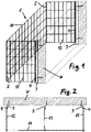
- the facade cladding gabion construction consists of gabion basket elements 1 mounted on a wall to be covered W, consisting of a front grille 11, intermediate grilles 12 and struts 13.
- the struts 13 are in FIGS figures 1 and 3 omitted for the sake of clarity because the wall is shown "transparent" there so that the gabion basket element can be seen better.
- the struts 13 are located.
- the front grille 11 and the intermediate grilles 12 can have a height selected from the point of view of practical handling and can be arranged one above the other along the wall W to be covered, adjoining one another, in order to form a gabion construction the desired height over part of the wall or over the entire wall.
- the gabion construction can also be expanded to the side in the desired manner by placing front grilles 11 sideways next to one another, with an intermediate grille 12 being provided at least at the lateral connection points between two laterally adjacent front grilles 11, which then has its end remote from the wall W connected to the both abutting front grilles 11 is connected.
- an intermediate grille 12 can also be provided in the course of each front grille (not shown).
- the struts 13 can be designed as individual strut rods, several of which can be spaced apart in height in the area of a gabion basket element; however, they can also be replaced by a coarser-meshed intermediate grid or by a normal intermediate grid 12 .
- Front grille 11 and intermediate grille 12, as in the figures 1 and 3 is shown, be connected to each other at their joints by conventional wire spirals 2.
- the intermediate grid 12 and the struts 13 are connected to the wall to be clad by means of vertical mounting rails arranged on the wall with corresponding mutual lateral spacings, which, if necessary assembled lengthwise, can run over the entire wall height or the area of the wall height to be clad .
- the mounting rails are designed as mounting rails 3 placed on the wall W and dowelled to the wall, which in the exemplary embodiment are designed as angle rails with an L-profile, one profile leg of which rests against the wall and the other profile leg with the intermediate grids 12 or the Struts 13 are connected.
- the connected to the intermediate grids 12 and the struts 13 profile leg of the mounting rails 3 is provided with a number of holes or openings, in which wire spirals 4 can engage, as in the embodiment according to Figures 1 and 2 can also be used to connect the intermediate grid 12 to the mounting rails 3, or in which the struts 13 can be hung with wire ends bent like hooks.
- the mounting rails are designed as mounting rails 5 integrated into the wall W, which have already been integrated into the wall during the production of the wall, in particular when it is designed as a concrete wall.
- the mounting rails 5 in turn provided with a row of holes, in which the intermediate grid 12 and the struts 13 are each hung with hook-shaped bent wire ends.
- the Figures 5, 6 and 7 show based on top views similar to the figures 2 and 4 other variants.
- the intermediate grid 12 and also the strut 13 designed as an intermediate grid are connected via wire spirals 4 to mounting rails 5 integrated into the wall W.
- connection of the intermediate grid 12 and the strut 13 to the wall W takes place via attached wall rails 3, as in the embodiment according to FIG Figures 1 and 2 , but not with wire spirals, but by hanging the intermediate grid 12 and the strut 13 in openings of the mounting rails 3.
- the intermediate grid 12 and the brace 13 designed as an intermediate grid are connected to the wall W via mounting rails 6 integrated into the wall, in which the ends of the intermediate grid 12 and the brace 13 designed as an intermediate grid are held in a form-fitting manner.
- Figures 8 to 13 show in the form of enlarged top view sections of figures 2 and 4 to 7 the wall joints used in the embodiments discussed above in more detail.
- figure 8 shows the embodiment according to FIG Figures 1 and 2 with a mounting rail 3 placed on the wall and connection of an intermediate grid 12 to the wall rail 3 by means of a wire spiral 4.
- FIG 9 shows the embodiment figure 5 with mounting rail 5 integrated into the wall and attachment of an intermediate grille 12 to the mounting rail by means of a wire spiral 4.
- the mounting rail 5 is designed in two parts here, namely with a mounting rail part 51 integrated into the wall with a profile head in which a guide channel running along the mounting rail part 51 is formed, which opens out to the outside in the form of a slot opening, and with a second, in the cross-sectional profile T-shaped mounting rail part 52, which is inserted into the guide channel and with a web part, which is connected to the intermediate grid 12, protrudes from the slot opening.
- the mounting rail part 51 integrated into the wall can be attached to the inside of a formwork for concreting the wall, so that after the wall has been completed, the outer surface of the profile head is flush with the wall, and after the formwork has been removed, the one with the intermediate grid can be attached 12 to be connected mounting rail part 52 are inserted into the guide channel.
- figure 10 shows the embodiment figure 6 , in which an intermediate grid 12 is hung in openings of a mounting rail 3 placed on the wall.
- figure 11 shows the embodiment according to FIG Figures 3 and 4 , where an intermediate grid 12 in a as in figure 9 again two-part design, integrated in the wall mounting rail 5 is hung.
- FIG 12 shows the embodiment figure 7 , in which the intermediate grid 12 is designed in a T-shape at its wall-side end in plan view in that a vertical grid rod is arranged at this end on both sides of the horizontal grid bars.
- the intermediate grid 12 is integrated into a wall Mounting rail 6 introduced, the mounting rail part 51 after the Figures 9 and 11 corresponds and has a positive-locking profile head with a guide channel which is open to the outside in the form of a slot opening, through which the horizontal bars of the intermediate grid 12 protrude.
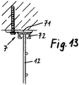
- FIG 13 shows in a representation similar to that Figures 8 to 12
- a mounting rail 7 placed on the wall consisting of a panel strip 71 placed on the wall and a form-fitting profile 72 welded onto it with a guide channel as in the mounting rails according to FIG Figures 9, 11 and 12 for receiving a trained with T-profile end of an intermediate grid 12 or an inserted mounting rail part similar to the mounting rail part 52 in the embodiment according to the Figures 9 and 11 .
- the plate 71 is anchored to the wall, for example by dowelling.
Abstract
Wandverkleidungs-Gabionenkonstruktion, die an einer zu verkleidenden Wand (W) anzubringenden Gabionenkorbelementen (1) aufweist. Die Gabionenkorbelemente (1) sind aus Frontgittern (11), die wandparallel vorderhalb der Wand (W) verlaufen, und aus zwischen den Frontgittern (11) und der Wand (W) verlaufenden Seiten- oder Zwischengittern (11) und gegebenenfalls zusätzlichen Verstrebungen (13) gebildet, die einerseits mit den Frontgittern (11) verbindbar und andererseits mit der Wand (W) verbindbar sind. Die Verbindung der Zwischengitter (12) und der gegebenenfalls vorhandenen Verstrebungen (13) mit der Wand (W) erfolgt über vertikal verlaufende Montageschienen (3; 5; 7), die ihrerseits mit der Wand (W) verbunden sind, und mit denen die Seiten- oder Zwischengitter (12) und die Verstrebungen (13) formschlüssig verbindbar sind.Wall cladding gabion construction, which has gabion basket elements (1) to be attached to a wall (W) to be clad. The gabion basket elements (1) consist of front grilles (11) that run parallel to the wall in front of the wall (W), and of side or intermediate grilles (11) that run between the front grilles (11) and the wall (W) and, if necessary, additional struts (13 ) formed, which can be connected to the front grilles (11) on the one hand and to the wall (W) on the other hand. The intermediate grille (12) and any struts (13) that may be present are connected to the wall (W) via vertical mounting rails (3; 5; 7), which in turn are connected to the wall (W) and to which the sides - Or intermediate grid (12) and the struts (13) are positively connected.
Description
Die Erfindung betrifft eine Gabionenkonstruktion zur Fassadenverkleidung, mit an der Fassade montierten Drahtgitter-Korbelementen, die mit einem Füllmaterial, insbesondere Steinen, befüllbar sind.The invention relates to a gabion construction for facade cladding, with wire mesh basket elements mounted on the facade, which can be filled with a filling material, in particular stones.
Die Verkleidung von Fassaden mittels Gabionen ist bereits bekannt. Aus der
Aus der
Aufgabe der Erfindung ist es daher, eine Fassadenverkleidungs-Gabionenkonstruktion zu schaffen, welche den Aufbau und die Montage einer Fassadenverkleidung in Gestalt von Gabionen an einer Wandfassade deutlich erleichtert.The object of the invention is therefore to create a facade cladding gabion construction which significantly facilitates the construction and installation of a facade cladding in the form of gabions on a wall facade.
Diese Aufgabe wird gemäß der Erfindung durch die im Anspruch 1 angeordnete und gemäß den Unteransprüchen weiter im einzelnen ausgebildete Anordnung gelöst.This object is achieved according to the invention by the arrangement arranged in claim 1 and further developed in detail according to the subclaims.
Bei der erfindungsgemäßen Wandverkleidungs-Gabionenkonstruktion sind Gabionenkorbelemente vorgesehen, die ohne Bodenwandgitter ausgebildet sein können und einen über die ganze Höhe der zu verkleidenden Wand durchgängig ununterbrochenen Gabionenraum herstellen können. Die Gabionenkorbelemente können aus Wand parallel vor der Wand verlaufenden Frontgittern, die der Höhe und der Breite nach aneinander gesetzt werden können, und aus Seiten- oder Zwischengittern sowie Verstrebungen bestehen können, die zwischen den Frontgittern und der Wand verlaufen und einerseits mit den Frontgittern verbunden und andererseits mit der Wand verbunden sind.In the wall cladding gabion construction according to the invention, gabion basket elements are provided which can be designed without a bottom wall grid and can create a continuously uninterrupted gabion space over the entire height of the wall to be clad. The gabion basket elements can consist of front grilles running parallel to the wall in front of the wall, which can be placed next to each other in height and width, and of side or intermediate grilles and struts, which run between the front grilles and the wall and are connected to the front grilles on the one hand and other hand connected to the wall.
Zur Fixierung der Gabionenkorbelemente an der zu verkleidenden Wand sind mit seitlichen Abständen entlang der zu verkleidenden Wand an dieser angeordnete, vertikal über die Höhe der zu verkleidenden Wand durchlaufende Montageschienen vorgesehen, die entweder nachträglich an der bereits bestehenden Wand durch Andübeln oder in anderer geeigneter Weise befestigt werden können, oder die bereits im Zuge der Herstellung einer insbesondere zu betonierenden Wand mittels beim Gießen des Betons in die Wand integrierter Verankerungen an der Wand befestigt werden können. Dabei ist auch die nachträgliche Montage der vertikalen Befestigungsleisten einfach durchzuführen, weil die Gabionenkorbelemente erst danach an den Befestigungsleisten angebracht werden und somit die Montage der Befestigungsleisten nicht durch Gabionenkorbelemente behindert oder erschwert wird.To fix the gabion basket elements to the wall to be clad, mounting rails arranged at lateral distances along the wall to be clad and running vertically over the height of the wall to be clad are provided, which are either subsequently attached to the existing wall by dowels or in another suitable manner can be, or already in the course of the production of a wall to be concreted, in particular, can be attached to the wall by means of anchors integrated into the wall when the concrete is poured. The subsequent assembly of the vertical fastening strips is also easy to carry out because the gabion basket elements are only then attached to the fastening strips and thus the assembly of the fastening strips is not impeded or made more difficult by gabion basket elements.
Die vertikalen Wandleisten können in verschiedener Weise für eine Schnellmontage von Drahtgitterwandteilen der Gabionenkorbelemente ausgebildet sein, wie nachstehend anhand einiger Ausführungsbeispiele erläutert wird.The vertical wall strips can be designed in various ways for quick assembly of wire mesh wall parts of the gabion basket elements, as will be explained below with reference to some exemplary embodiments.
Einige Ausführungsbeispiele der Erfindung sind in den anliegenden Zeichnungen dargestellt und werden nachstehend unter Bezugnahme auf diese Zeichnungen mehr im einzelnen beschrieben, in denen zeigt:
- Fig. 1
- in schematischer perspektivischer Ansicht ein an einer zu verkleidenden Wand montiertes Gabionenkorbelement mit auf der Wand aufgesetzten Montageschienen,
- Fig. 2
- eine Draufsicht der Anordnung nach
Figur 1 , - Fig. 3
- eine perspektivische Ansicht ähnlich
Figur 1 mit in die Wand integrierten Montageschienen, - Fig. 4
- eine Draufsicht der Anordnung nach
Fig. 3 , - die Fig. 5 - 7
- Draufsichten ähnlich den
Figuren 24 von weiteren Varianten der erfindungsgemäßen Konstruktion, - die Fig. 8 - 12
- vergrößerte Horizontalschnitt-Ausschnitte aus den
Figuren 4 und5-7 , die jeweils die Wandmontage im Bereich einer Wand-schiene zeigen, und - Fig. 13
- eine weitere Ausführungsvariante der Wandmontage.
- 1
- in a schematic perspective view, a gabion basket element mounted on a wall to be clad with mounting rails placed on the wall,
- 2
- a top view of the arrangement
figure 1 , - 3
- a perspective view similar
figure 1 with mounting rails integrated into the wall, - 4
- a top view of the
arrangement 3 , - Figures 5 - 7
- Plan views similar to
figures 2 and4 of further variants of the construction according to the invention, - Figures 8 - 12
- enlarged horizontal sections from the
figures 2 ,4 and5-7 , each showing wall mounting in the area of a wall rail, and - 13
- another variant of wall mounting.
Wie in den
Das Frontgitter 11 und die Zwischengitter 12 können eine nach Gesichtspunkten zweckmäßiger Handhabbarkeit gewählte Höhe haben und können entlang der zu verkleidenden Wand W aneinander anschließend übereinander angeordnet werden, um eine Gabionenkonstruktion der gewünschten Höhe über einen Teil der Wand oder über die gesamte Wand herzustellen. Auch nach der Seite kann die Gabionenkonstruktion durch seitwärts aneinander gesetzte Frontgitter 11 in der gewünschten Weise ausgedehnt werden, wobei mindestens an den seitlichen Anschlusstellen zwischen zwei seitlich benachbarten Frontgittern 11 ein Zwischengitter 12 vorgesehen ist, das mit seinem von der Wand W entfernten Ende dann mit den beiden aneinanderstoßenden Frontgittern 11 verbunden ist.The
Je nach der seitwärtigen Ausdehnung (Länge) der Frontgitter 11 kann auch im Verlauf jedes Frontgitters noch ein Zwischengitter 12 vorgesehen sein (nicht dargestellt).Depending on the lateral extent (length) of the
Die Verstrebungen 13 können als einzelne Verstrebungsstäbe ausgebildet sein, von welchen mehrere der Höhe nach beabstandet im Bereich eines Gabionenkorbelements vorgesehen sein können; sie können aber auch durch ein gröbermaschiges Zwischengitter oder durch ein normales Zwischengitter 12 ersetzt werden.The
Frontgitter 11 und Zwischengitter 12 können, wie in den
Die Verbindung der Zwischengitter 12 und der Verstrebungen 13 mit der zu verkleidenden Wand erfolgt über an der Wand mit entsprechenden gegenseitigen seitlichen Abständen angeordnete vertikale Montageschienen, die, gegebenenfalls der Länge nach zusammengesetzt, über die gesamte Wandhöhe bzw. den zu verkleidenden Bereich der Wandhöhe verlaufen können.The
Bei dem Ausführungsbeispiel nach den
Bei dem Ausführungsbeispiel nach den
Bei dem Ausfiihrungsbeispiel nach den
Die
Bei der Ausführungsform nach
Bei der Ausführungsform nach
Bei der Ausführungsform nach
Die
Claims (6)
dadurch gekennzeichnet, dass die Gabionenkorbelemente (1) aus Frontgittern (11), die wandparallel vorderhalb der Wand (W) verlaufen, und aus zwischen den Frontgittern (11) und der Wand (W) verlaufenden Seiten- oder Zwischengittern (11) und gegebenenfalls zusätzlichen Verstrebungen (13) gebildet sind, die einerseits mit den Frontgittern (11) verbindbar und andererseits mit der Wand (W) verbindbar sind,
und dass die Verbindung der Zwischengitter (12) und der gegebenenfalls vorhandenen Verstrebungen (13) mit der Wand (W) über vertikal verlaufende Montageschienen (3; 5; 7) erfolgt, die ihrerseits mit der Wand (W) verbunden sind, und mit denen die Seiten- oder Zwischengitter (12) und die Verstrebungen (13) formschlüssig verbindbar sind.Wall cladding gabion construction, with gabion basket elements (1) to be attached to a wall (W) to be clad,
characterized in that the gabion basket elements (1) consist of front grilles (11), which run parallel to the wall in front of the wall (W), and of side or intermediate grilles (11) running between the front grilles (11) and the wall (W), and possibly additional ones struts (13) are formed, which can be connected to the front grilles (11) on the one hand and to the wall (W) on the other hand,
and that the connection between the intermediate grilles (12) and any struts (13) present with the wall (W) takes place via vertically running mounting rails (3; 5; 7), which in turn are connected to the wall (W) and to which the side or intermediate grilles (12) and the struts (13) can be positively connected.
Applications Claiming Priority (1)
| Application Number | Priority Date | Filing Date | Title |
|---|---|---|---|
| DE202020004662.0U DE202020004662U1 (en) | 2020-11-05 | 2020-11-05 | Facade cladding gabion construction |
Publications (1)
| Publication Number | Publication Date |
|---|---|
| EP3995644A1 true EP3995644A1 (en) | 2022-05-11 |
Family
ID=74565057
Family Applications (1)
| Application Number | Title | Priority Date | Filing Date |
|---|---|---|---|
| EP21000263.0A Pending EP3995644A1 (en) | 2020-11-05 | 2021-09-20 | Facade cladding gabion structure |
Country Status (2)
| Country | Link |
|---|---|
| EP (1) | EP3995644A1 (en) |
| DE (1) | DE202020004662U1 (en) |
Citations (6)
| Publication number | Priority date | Publication date | Assignee | Title |
|---|---|---|---|---|
| CN2375695Y (en) * | 1999-06-29 | 2000-04-26 | 林国祥 | T-shaped steel frame structure for ceiling |
| DE202008015923U1 (en) * | 2008-11-25 | 2009-02-26 | Luz Ohg | Carrier for a gabion wall |
| EP2163706A2 (en) * | 2008-09-16 | 2010-03-17 | Konrad Lehrhuber | Wall cladding with filling material |
| DE202011052161U1 (en) | 2011-12-01 | 2012-01-19 | Remigiusz Dawidowski | gabion |
| EP2894274A2 (en) | 2013-12-30 | 2015-07-15 | Wolfgang Deutschle | Facade cladding gabion |
| EP3346058A1 (en) * | 2017-01-09 | 2018-07-11 | Beckert Diplom-Wirtschaftsingenieur Manfred | Gabion wall module and method for producing a gabion wall with at least one gabion wall module |
-
2020
- 2020-11-05 DE DE202020004662.0U patent/DE202020004662U1/en active Active
-
2021
- 2021-09-20 EP EP21000263.0A patent/EP3995644A1/en active Pending
Patent Citations (6)
| Publication number | Priority date | Publication date | Assignee | Title |
|---|---|---|---|---|
| CN2375695Y (en) * | 1999-06-29 | 2000-04-26 | 林国祥 | T-shaped steel frame structure for ceiling |
| EP2163706A2 (en) * | 2008-09-16 | 2010-03-17 | Konrad Lehrhuber | Wall cladding with filling material |
| DE202008015923U1 (en) * | 2008-11-25 | 2009-02-26 | Luz Ohg | Carrier for a gabion wall |
| DE202011052161U1 (en) | 2011-12-01 | 2012-01-19 | Remigiusz Dawidowski | gabion |
| EP2894274A2 (en) | 2013-12-30 | 2015-07-15 | Wolfgang Deutschle | Facade cladding gabion |
| EP3346058A1 (en) * | 2017-01-09 | 2018-07-11 | Beckert Diplom-Wirtschaftsingenieur Manfred | Gabion wall module and method for producing a gabion wall with at least one gabion wall module |
Also Published As
| Publication number | Publication date |
|---|---|
| DE202020004662U1 (en) | 2021-01-22 |
Similar Documents
| Publication | Publication Date | Title |
|---|---|---|
| DE2344178C2 (en) | Countersink with fixed ballast | |
| DE2727159C3 (en) | Shear reinforcement for flat slabs made of reinforced or prestressed concrete on concrete supports | |
| EP1589156B1 (en) | Element for connecting prefinished concrete elements | |
| DE2629917A1 (en) | STRUCTURE MADE OF PANEL-SHAPED, IN PARTICULAR CERAMIC ELEMENTS | |
| AT518814B1 (en) | Fence system and assembly process for a fence system | |
| DE4208964C2 (en) | Steep embankment | |
| DE3820700C2 (en) | ||
| EP2172601B1 (en) | Freely suspended stairs | |
| DE1811932A1 (en) | Concrete beams, especially for grids and retaining walls | |
| EP2716839B1 (en) | Formwork element | |
| DE102012217689A1 (en) | Wall formwork and wall formwork system | |
| EP0117443B1 (en) | Heat insulated permanent form for wall constructions | |
| EP3995644A1 (en) | Facade cladding gabion structure | |
| DE102007044017A1 (en) | Wall element i.e. hollow wall block, for forming noise protection wall, has grid structure inserted into slot as connecting element to connect adjacent wall component with end section, and fixed transversal to longitudinal direction of slot | |
| EP0410335A2 (en) | Reinforcing member for the formation of support frames in tunnelling | |
| DE2513268C3 (en) | Noise protection wall or wall, especially for motorways | |
| AT411079B (en) | METHOD FOR THE CONSTRUCTION OF A CONSTRUCTION WITH A CONCRETE WALL CONTAINED IN A CIRCUMFERENCE | |
| EP1101883B1 (en) | Method for the execution of a reinforcement connection between a concrete construction element and a connected construction element | |
| DE1684544A1 (en) | Prefabricated barracks or the like. | |
| DE4332793C1 (en) | Process for producing structures, and prefabricated module | |
| DE2120883B2 (en) | Prefabricated component composed of roller shutter box and window | |
| EP2312062B1 (en) | Gabions | |
| DE19849360C1 (en) | Prison safe-custody room grating comprizes edge reinforcement at room opening anchored in building wall and held in manganese steel box frame for maximum resistance. | |
| AT400467B (en) | AUXILIARY DEVICE FOR USE IN THE AREA OF WINDOW OR PASSWAY OPENINGS AND CORNERS FOR THE CREATION OF WALLS MADE FROM A WALL | |
| DE1684357C3 (en) |
Legal Events
| Date | Code | Title | Description |
|---|---|---|---|
| PUAI | Public reference made under article 153(3) epc to a published international application that has entered the european phase |
Free format text: ORIGINAL CODE: 0009012 |
|
| STAA | Information on the status of an ep patent application or granted ep patent |
Free format text: STATUS: THE APPLICATION HAS BEEN PUBLISHED |
|
| AK | Designated contracting states |
Kind code of ref document: A1 Designated state(s): AL AT BE BG CH CY CZ DE DK EE ES FI FR GB GR HR HU IE IS IT LI LT LU LV MC MK MT NL NO PL PT RO RS SE SI SK SM TR |
|
| STAA | Information on the status of an ep patent application or granted ep patent |
Free format text: STATUS: REQUEST FOR EXAMINATION WAS MADE |
|
| 17P | Request for examination filed |
Effective date: 20220907 |
|
| RBV | Designated contracting states (corrected) |
Designated state(s): AL AT BE BG CH CY CZ DE DK EE ES FI FR GB GR HR HU IE IS IT LI LT LU LV MC MK MT NL NO PL PT RO RS SE SI SK SM TR |