EP2716839B1 - Formwork element - Google Patents
Formwork element Download PDFInfo
- Publication number
- EP2716839B1 EP2716839B1 EP13004724.4A EP13004724A EP2716839B1 EP 2716839 B1 EP2716839 B1 EP 2716839B1 EP 13004724 A EP13004724 A EP 13004724A EP 2716839 B1 EP2716839 B1 EP 2716839B1
- Authority
- EP
- European Patent Office
- Prior art keywords
- formwork element
- projections
- reinforcement
- formwork
- longitudinal
- Prior art date
- Legal status (The legal status is an assumption and is not a legal conclusion. Google has not performed a legal analysis and makes no representation as to the accuracy of the status listed.)
- Active
Links
- 238000009415 formwork Methods 0.000 title claims description 64
- 230000002787 reinforcement Effects 0.000 claims description 51
- 238000003780 insertion Methods 0.000 claims description 6
- 230000037431 insertion Effects 0.000 claims description 6
- 239000012815 thermoplastic material Substances 0.000 claims description 2
- 238000005259 measurement Methods 0.000 claims 2
- 150000001875 compounds Chemical class 0.000 claims 1
- 230000003014 reinforcing effect Effects 0.000 description 48
- 238000004519 manufacturing process Methods 0.000 description 4
- 238000010276 construction Methods 0.000 description 3
- 239000000463 material Substances 0.000 description 3
- 238000000034 method Methods 0.000 description 3
- 238000009416 shuttering Methods 0.000 description 3
- 229910000831 Steel Inorganic materials 0.000 description 2
- 238000009434 installation Methods 0.000 description 2
- 239000004033 plastic Substances 0.000 description 2
- 230000000630 rising effect Effects 0.000 description 2
- 230000003068 static effect Effects 0.000 description 2
- 239000010959 steel Substances 0.000 description 2
- 230000003466 anti-cipated effect Effects 0.000 description 1
- 230000015572 biosynthetic process Effects 0.000 description 1
- 238000005260 corrosion Methods 0.000 description 1
- 230000007797 corrosion Effects 0.000 description 1
- 238000001035 drying Methods 0.000 description 1
- 230000007613 environmental effect Effects 0.000 description 1
- 239000007788 liquid Substances 0.000 description 1
- 230000007704 transition Effects 0.000 description 1
Images


Classifications
-
- E—FIXED CONSTRUCTIONS
- E04—BUILDING
- E04C—STRUCTURAL ELEMENTS; BUILDING MATERIALS
- E04C5/00—Reinforcing elements, e.g. for concrete; Auxiliary elements therefor
- E04C5/16—Auxiliary parts for reinforcements, e.g. connectors, spacers, stirrups
- E04C5/20—Auxiliary parts for reinforcements, e.g. connectors, spacers, stirrups of material other than metal or with only additional metal parts, e.g. concrete or plastics spacers with metal binding wires
-
- E—FIXED CONSTRUCTIONS
- E04—BUILDING
- E04C—STRUCTURAL ELEMENTS; BUILDING MATERIALS
- E04C5/00—Reinforcing elements, e.g. for concrete; Auxiliary elements therefor
- E04C5/16—Auxiliary parts for reinforcements, e.g. connectors, spacers, stirrups
- E04C5/168—Spacers connecting parts for reinforcements and spacing the reinforcements from the form
-
- E—FIXED CONSTRUCTIONS
- E04—BUILDING
- E04G—SCAFFOLDING; FORMS; SHUTTERING; BUILDING IMPLEMENTS OR AIDS, OR THEIR USE; HANDLING BUILDING MATERIALS ON THE SITE; REPAIRING, BREAKING-UP OR OTHER WORK ON EXISTING BUILDINGS
- E04G13/00—Falsework, forms, or shutterings for particular parts of buildings, e.g. stairs, steps, cornices, balconies foundations, sills
- E04G13/04—Falsework, forms, or shutterings for particular parts of buildings, e.g. stairs, steps, cornices, balconies foundations, sills for lintels, beams, or transoms to be encased separately; Special tying or clamping means therefor
-
- E—FIXED CONSTRUCTIONS
- E04—BUILDING
- E04G—SCAFFOLDING; FORMS; SHUTTERING; BUILDING IMPLEMENTS OR AIDS, OR THEIR USE; HANDLING BUILDING MATERIALS ON THE SITE; REPAIRING, BREAKING-UP OR OTHER WORK ON EXISTING BUILDINGS
- E04G17/00—Connecting or other auxiliary members for forms, falsework structures, or shutterings
- E04G17/06—Tying means; Spacers ; Devices for extracting or inserting wall ties
- E04G17/064—Spacers placed on the bottom of the mould
Definitions
- the present invention relates to a formwork element with two laterally spaced formwork panels, which are interconnected by at least a plurality of connecting elements and define between them fillable with a filling material formwork space, in which a configured for fixing the position of reinforcing bars rebar basket can be inserted, wherein in the Interspace between two adjacent connecting elements a reinforcing member is inserted, which has receptacles for attachment of a reinforcing cage forming wireforms.
- a generic formwork element is from the font "Rekord Holzmann GmbH & Co. KG Delivery Program Price List 2012 and from the Scriptures DE 102 00 251 A1 known. From the Scriptures FR 2739886 A1 is also a generic formwork element known. From the Scriptures EN 20 2010 It is known to attach to the fasteners wireforms that are shaped so that there is a positional fixation of inserted into the formwork element reinforcing bars. The wireforms may form part of a ring around a reinforcement, or the wireforms form a ring alone or together with other wireforms. By attaching the wireforms to the connecting elements, it is necessary to provide as many connecting elements on the formwork element as required by the minimum distance between the wireforms.
- the reinforcing member has at its connectable with the connecting elements locking elements for locking with corresponding latching openings in the connecting elements, and the reinforcing member has at least one longitudinal web, laterally projecting from the webs on which the recordings are formed ..
- the reinforcement component By means of the reinforcement component, it is possible to connect wireforms to the formwork element even in the intermediate spaces between connecting elements.
- 4 fasteners are available to connect the two formwork panels sufficiently firmly together. If the distance between the connecting elements is 47 cm, three reinforcing components can be inserted into the intermediate spaces between the connecting elements. Depending on the reinforcement component, wireforms can then be fastened in three places in order to maintain the distance of at most 15 cm per ring.
- the reinforcement component can also be used independently of a formwork element to produce a reinforcement cage for a reinforcement of a concrete component.
- the reinforcement component per se does not form part of the invention. For this purpose, reinforcing components are strung together over the length of the reinforcement to be produced, reinforcement bars are inserted and the wireforms required for the production of the reinforcing cage are inserted into the reinforcement components.
- a reinforcement cage is required to hold reinforcing bars of a reinforcement within a desired cross-section in a shell installation position. While the reinforcing bars usually can have larger material cross sections depending on the load to be produced in the component, it is sufficient for the forming a strapping wireforms, if they are processed in thinner material cross sections, since they have to position only the reinforcing rods within the concrete component and not static To have loads.
- the reinforcing member has at its connectable with the connecting elements ends locking elements for locking with corresponding Latching openings in the connecting elements.
- the locking elements may be attached to angled to the main plane of the reinforcing member legs, with which the bottom side profile leg can be engaged behind.
- Locking lugs can engage in recesses, which are located in the connecting elements. By locking the reinforcing member this is sufficiently strong to hold the reinforcing bars during concrete pouring in the intended target position. Once the concreting process has been completed, the concrete hardens and the reinforcing component becomes inoperative.
- the locking lugs can be dimensioned so that they provide sufficient strength for the concreting process.
- the reinforcing member has a longitudinal ridge, projecting laterally from the webs, where the recordings are attached.
- the construction with a longitudinal web with laterally projecting webs results in a Sketett Modell that leaves the concrete in the formwork element still sufficient space to distribute evenly and to fill its static functions in the extent anticipated.
- the reinforcement component can be made in one piece in the skeleton structure, which makes it easier to handle and install.
- the reinforcing member is made of a thermoplastic material.
- the plastic is not subject to any corrosion problem, it is inexpensive to procure and process and it works well with the concrete environment.
- the wireforms can be designed so that they fix the reinforcing bars in a desired installation position, in the lateral direction as well as in their altitude. It is also possible to connect a plurality of wireforms to the reinforcement component one after the other, for example a first wireform at several points of the reinforcement component in order first to position reinforcing rods in a lower position in the formwork element, and then a second wireform at several points of the reinforcement component, through the further ones Reinforcing bars can be positioned in a higher position in the formwork element.
- the longitudinal web on several sides projecting webs. Due to the formation of the longitudinal web as a central web, the reinforcing component can be positioned centrally in the formwork element. The wireforms can then be easily connected to the recordings, far as they are easily accessible.
- opposing webs at a location of the longitudinal web on at least two pairs of shots By several Shooting it is possible to attach at one point of the reinforcement component also several wireforms. This can be advantageous if several layers of reinforcing bars are to be installed in the finished concrete component.
- receptacles are designed as plug-in sleeves. Through sockets, the wireforms in the insertion area get a good guide, so that they can not be easily removed from their installed position, for example, when concrete is poured into the formwork component.
- additional fastening clips are arranged on the longitudinal web, the webs and / or the sockets.
- the fastening clips it is possible, for example, to fix wireforms as upwardly open U on the reinforcement component. This would not be possible in the sockets, because the wire ends of the wireforms can be inserted only with the free ends down in the sockets.
- To form a ring it is not necessary to form the ring closed with connected ends of two U-wireforms, it is sufficient if the free legs of the U-shaped wireforms have a sufficiently long overlap region in the longitudinal direction of the free legs. The connection between the two wireforms later represents the cast and cured. Concrete.
- the end-side connecting elements of a formwork element are arranged less than 7.5 cm from the end face of a formwork element. By this measure, it can be dispensed with the juxtaposition of formwork elements to have to insert in the interface between two adjacent formwork elements and a reinforcement component.
- the minimum distance between the two end-side connecting elements of the abutting shuttering elements in the proposed embodiment is less than 15 cm, so that it is sufficient if a ring in the transition region from one to the next formwork element is formed in each case at the connecting element.
- one or more wireforms which are open at the top and / or bottom are fastened to the reinforcement component, for example in the form of an upwardly open U, in order to be able to insert a reinforcing rod or a downwardly open U for partially strapping an already inserted reinforcing bar with the U open at the bottom.
- the pre-assembled wireforms simplify the production of the reinforcement cage at the construction site. All that remains is to place the reinforcement bars in the space delimited by the preassembled wireform, in order then to insert a counter-rotating wireform into the associated receptacle, thereby forming a finished reinforcement ring from the two wireforms overlapping the free legs to accomplish.
- the production of a reinforcement basket is thus limited to the insertion of the reinforcing bars in the formwork element and the subsequent insertion of the wireforms in the existing recordings.
- the reinforcing member has two spaced apart longitudinal webs, which are interconnected by at least two webs, and in the region of the longitudinal webs interconnecting webs are arranged upwardly from the longitudinal webs upstanding webs, which together with the longitudinal webs and the connecting webs form slotted channels in which wireforms are supported supported by the sidewalls of the slotted channels.
- the inner edge of the uprights projecting from the longitudinal webs on a distance to the outer edge of the towering from the longitudinal webs ridges which corresponds to a standard concrete Betondeckungshack. Due to the distance by which the inner edge is spaced from the outer edge, and the reinforcing rods can be inserted necessarily only with maximum this distance to the outer edges of the webs in the reinforcement member. If the distance between the inner edge and the outer edge of the webs projecting from the longitudinal webs corresponds to the standard concrete cover factor, the reinforcing rods are inevitably always installed with a standard concrete concrete cover dimension in the concrete component to be produced. The extent to which the reinforcing steels must at least be covered by concrete is determined by the respective environmental conditions and exposure classes, for example from the standard DIN EN 1045 and the DIN EN 206 or the following standards.
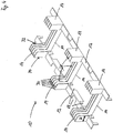
- Fig. 1 is a view obliquely from above of a formwork element 2 shown.
- the formwork panels 4 are shown only in dashed lines.
- the shuttering panels 4 are connected to each other in the embodiment by two connecting elements 6.
- the formwork panels 4 define between them a formwork space 8, can be filled in the concrete.
- the reinforcing construction part 10 essentially consists of a longitudinal web 12, from which webs 14 protrude laterally. On the webs 14 receptacles 16 are formed, which are formed in the embodiment as sockets.
- the reinforcing member 10 also has recesses 18 through which the concrete flow into the shuttering space underneath and can completely fill it.
- the reinforcement component 10 has latching elements 20 on the end sides.
- the locking elements 20 are elevations that can be engaged in complementarily shaped latching openings 22 which are located in the connecting elements 6.
- Fig. 2 It is shown how reinforcing bars 26 can be placed on wireforms 24 to be fixed in position within the formwork space 8.
- the wireforms 24 are inserted into the receptacles 16.
- the wireforms 24 are shaped so that the reinforcing bars 26 can be positioned at a desired height within the formwork element 2 and the formwork space 8.
- Fig. 2 are shown in the embodiment shown there only wireforms 24 which have a U-shape, the open end facing down. Deviating from this embodiment, wireforms can be clipped to the receptacles 16, the open end facing upward. It is also possible to put on top reinforcing bars 26 still wireforms with downwardly pointing legs to achieve a height-wise overlap of the legs with legs lower lying wireforms 24.
- Fig. 3 is a view is shown on the front side of a formwork element 2.
- the formwork element 2 with a pre-assembled wire 24a.
- the reinforcing rods 26 inserted and then the wireform 24b with the free legs down in the associated receptacle 16 is inserted.
- the two wireforms 24a, 24b form together by the overlapping area Ü, in which the free legs of the wireforms 24a, 24b overlap, a strapping around the reinforcing bars 26, which can be formed at any point of a web by simply inserting the wireform 24b.
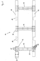
- Fig. 4 is a view obliquely from above of a second embodiment of a reinforcing member 10 is shown.
- the reinforcement member 10 has two longitudinal webs 12 which are spaced and arranged parallel to each other.
- the dimensions of the reinforcement component 10 are dimensioned such that it can be inserted into the formwork space 8 of a formwork element 2.
- the longitudinal webs 12 have recesses 18, can run through the freshly poured into the formwork space concrete in the area covered by the longitudinal webs 12 area, so that there are no voids in the finished concrete component.
- reinforcement member 10 is preferably made of a plastic.
- the longitudinal webs 12 are interconnected by a total of three webs 14 which protrude in the lateral direction of the longitudinal webs 12.
- the combination of the longitudinal webs 12 with the connecting webs 14 forms a base with which the Be Wehrungsbauteil 10 can be placed on a subjacent underlying tip over. Due to the larger surface covering base, it is not absolutely necessary to connect the reinforcement member 10 with the connecting elements 6 of a formwork element 2.
- a reinforcement member 10 can be placed on a wall crown, but also on a concrete surface, a floor or other surfaces, even independently of a formwork element. 2
- the inner edge 32 of the webs 14 rising up from the longitudinal webs 12 is arranged at a distance to the outer edge 34 of the webs 14 rising from the longitudinal webs 12, which results from the depth of the corresponding side walls 30.
- the distance dimension ei preferably corresponds If a reinforcing rod parallel to the longitudinal direction of the reinforcing member 10 is inserted into the space between neigh hard webs 14, this inevitably also holds such a distance to the outer surface of the concrete component that a sufficient Betondeckungsgrad the reinforcement is given.
- Fig. 5 is that in Fig. 4 shown second embodiment of a Bewehruhgsbauteils 10 shown in a view from above.
- the slotted channels 28 bounded by the sidewalls 30 are clearly visible.
- the slotted channels 28 have in their course recesses 18 so that liquid concrete can fill all the cavities in the vicinity of the reinforcement member 10. While only two slotted channels 28 are formed in the region of the connecting webs 14, there are four slotted channels in the region of the upwardly projecting webs 14.
- the inwardly facing side walls 30 of the two longitudinal webs 12 are lowered in the embodiment in order to increase the free cross section of the slotted channels 28 in their course, but still available to increase the longitudinal stability and torsional stiffness of the longitudinal webs 12 and an additional support and leadership allow for inserted into the slotted channels 28 wireforms 24.
Description
Die vorliegende Erfindung bezieht sich auf ein Schalungselement mit zwei seitlich voneinander beabstandeten Schalungsplatten, die durch zumindest mehrere Verbindungselemente miteinander verbunden sind und die zwischen sich einen mit einer Füllmasse ausfüllbaren Schalungsraum begrenzen, in den ein zur Lagefixierung von Bewehrungsstäben ausgestalteter Bewehrungskorb einlegbar ist, wobei in den Zwischenraum zwischen zwei benachbarten Verbindungselementen ein Bewehrungsbauteil eingelegt ist, das Aufnahmen zur Befestigung von einen Bewehrungskorb bildenden Drahtgebilden aufweist.The present invention relates to a formwork element with two laterally spaced formwork panels, which are interconnected by at least a plurality of connecting elements and define between them fillable with a filling material formwork space, in which a configured for fixing the position of reinforcing bars rebar basket can be inserted, wherein in the Interspace between two adjacent connecting elements a reinforcing member is inserted, which has receptacles for attachment of a reinforcing cage forming wireforms.
Ein gattungsgemäßes Schalungselement eist aus der Schrift "Rekord Holzmann GmbH & Co. KG Lieferprogramm Preisliste 2012 sowie aus der Schrift
Es ist die Aufgabe der vorliegenden Erfindung, eine Lösung zu schaffen, bei der zur Herstellung eines Bewehrungskorbes auf einfache Weise-Drahtgebilde mit dem Schalungselement verbunden werden können, ohne dass es dafür erforderlich ist, die Anzahl der in das Schalungselement eingebauten Verbindungselemente über ein normales Maß hinaus zu erhöhen.It is the object of the present invention to provide a solution in which can be connected to the production of a reinforcing basket in a simple way wireforms with the formwork element, without it being necessary for the number of installed in the formwork element fasteners above a normal level to increase out.
Die Aufgabe wird für ein gattungsgemäßes Schalungselement gelöst, indem das Bewehrungsbauteil an seinen mit den Verbindungselementen verbindbaren Enden Rastelemente zur Verrastung mit entsprechenden Rastöffnungen in den Verbindungselementen aufweist, und das Bewehrungsbauteil zumindest einen Längssteg aufweist, von dem Stege seitlich abstehen, an denen die Aufnahmen ausgebildet sind..
Durch das Bewehrungsbauteil ist es möglich, auch in den Zwischenräumen zwischen Verbindungselementen Drahtgebilde mit dem Schalungselement zu verbinden. Bei einem beispielhaft 2 m langen Schalungselement sind üblicherweise 4 Verbindungselemente vorhanden, um die beiden Schalungsplatten ausreichend fest miteinander zu verbinden. Beträgt der Abstand zwischen den Verbindungselementen 47 cm, können in die Zwischenräume zwischen den Verbindungselementen drei Bewehrungsbauteile eingesetzt werden. Je Bewehrungsbauteil können dann an drei Stellen Drahtgebilde befestigbar sein, um das Abstandsmaß von höchstens 15 cm je Ring einzuhalten.The object is achieved for a generic formwork element by the reinforcing member has at its connectable with the connecting elements locking elements for locking with corresponding latching openings in the connecting elements, and the reinforcing member has at least one longitudinal web, laterally projecting from the webs on which the recordings are formed ..
By means of the reinforcement component, it is possible to connect wireforms to the formwork element even in the intermediate spaces between connecting elements. In an exemplary 2 m long formwork element usually 4 fasteners are available to connect the two formwork panels sufficiently firmly together. If the distance between the connecting elements is 47 cm, three reinforcing components can be inserted into the intermediate spaces between the connecting elements. Depending on the reinforcement component, wireforms can then be fastened in three places in order to maintain the distance of at most 15 cm per ring.
Zur Montage des Bewehrungsbauteils reicht es aus, dieses in das Schalungselement einzulegen. Dabei bietet es sich an, die Maße des Bewehrungsbauteils so auszugestalten, dass es genau von einem Verbindungselement zum nächsten benachbarten Verbindungselement reicht.For mounting the reinforcing member, it is sufficient to insert this in the formwork element. It makes sense to design the dimensions of the reinforcement component so that it extends exactly from one connection element to the next adjacent connection element.
Das Bewehrungsbauteil kann auch unabhängig von einem Schalungselement dazu benutzt werden, einen Bewehrungskorb für eine Bewehrung eines Betonbauteils herzustellen. Das Bewehrungsbauteil an sich stellt keinen Teil der Erfindung dar. Dazu werden über die Länge der herzustellenden Bewehrung Bewehrungsbauteile aneinandergereiht, Bewehrungsstäbe eingelegt und die für die Herstellung des Bewehrungskorbes benötigten Drahtgebilde in die Bewehrungsbauteile eingesteckt.The reinforcement component can also be used independently of a formwork element to produce a reinforcement cage for a reinforcement of a concrete component. The reinforcement component per se does not form part of the invention. For this purpose, reinforcing components are strung together over the length of the reinforcement to be produced, reinforcement bars are inserted and the wireforms required for the production of the reinforcing cage are inserted into the reinforcement components.
Ein Bewehrungskorb ist erforderlich, um Bewehrungsstäbe einer Bewehrung innerhalb eines gewünschten Querschnitts in einer Solleinbaulage zu halten. Während die Bewehrungsstäben üblicherweise je nach im herzustellenden Bauteil aufzunehmender Last über stärkere Materialquerschnitte verfügen können, genügt es für die eine Umreifung bildenden Drahtgebilde, wenn diese in dünneren Materialquerschnitten verarbeitet werden, da sie nur die Bewehrungsstäbe innerhalb des Betonbauteils zu positionieren haben und für sich keine statischen Lasten aufzunehmen haben.A reinforcement cage is required to hold reinforcing bars of a reinforcement within a desired cross-section in a shell installation position. While the reinforcing bars usually can have larger material cross sections depending on the load to be produced in the component, it is sufficient for the forming a strapping wireforms, if they are processed in thinner material cross sections, since they have to position only the reinforcing rods within the concrete component and not static To have loads.
Das Bewehrungsbauteil weist an seinen mit den Verbindungselementen verbindbaren Enden Rastelemente zur Verrastung mit entsprechenden Rastöffnungen in den Verbindungselementen auf. So können die Rastelemente an zur Hauptebene des Bewehrungsbauteils angewinkelten Schenkeln angebracht sein, mit denen der bodenseitige Profilschenkel hintergriffen werden kann. Rastnasen können in Ausnehmungen einrasten, die sich in den Verbindungselementen befinden. Durch die Verrastung des Bewehrungsbauteils ist dieses ausreichend fest, um die Bewehrungsstäbe beim Betongießen in der vorgesehenen Sollposition zu halten. Ist der Betoniervorgang beendet, härtet der Beton aus, und das Bewehrungsbauteil ist dann funktionslos. Die Rastnasen können so dimensioniert werden, dass sie eine ausreichende Festigkeit für den Betoniervorgang bieten. Das Bewehrungsbauteil weist einen Längssteg auf, von dem Stege seitlich abstehen, an denen die Aufnahmen befestigt sind. Durch die Konstruktion mit einem Längssteg mit seitlich abstehenden Stegen ergibt sich eine Sketettstruktur, die dem Beton im Schalungselement noch ausreichend Raum lässt, sich gleichmäßig zu verteilen und seine statischen Funktionen im vorhergesehenen Umfang auszufüllen. Das Bewehrungsbauteil kann in der Skelettstruktur einteilig hergestellt sein, was es leichter handhabbar und einbaubar macht.The reinforcing member has at its connectable with the connecting elements ends locking elements for locking with corresponding Latching openings in the connecting elements. Thus, the locking elements may be attached to angled to the main plane of the reinforcing member legs, with which the bottom side profile leg can be engaged behind. Locking lugs can engage in recesses, which are located in the connecting elements. By locking the reinforcing member this is sufficiently strong to hold the reinforcing bars during concrete pouring in the intended target position. Once the concreting process has been completed, the concrete hardens and the reinforcing component becomes inoperative. The locking lugs can be dimensioned so that they provide sufficient strength for the concreting process. The reinforcing member has a longitudinal ridge, projecting laterally from the webs, where the recordings are attached. The construction with a longitudinal web with laterally projecting webs results in a Sketettstruktur that leaves the concrete in the formwork element still sufficient space to distribute evenly and to fill its static functions in the extent anticipated. The reinforcement component can be made in one piece in the skeleton structure, which makes it easier to handle and install.
Nach einer Ausgestaltung der Erfindung ist das Bewehrungsbauteil aus einem thermoplastischen Kunststoff hergestellt. Der Kunststoff unterliegt keinem Korrosionsproblem, er ist kostengünstig beschaffbar und verarbeitbar und er verträgt sich gut mit der Betonumgebung.According to one embodiment of the invention, the reinforcing member is made of a thermoplastic material. The plastic is not subject to any corrosion problem, it is inexpensive to procure and process and it works well with the concrete environment.
Die Drahtgebilde können so ausgestaltet sein, dass sie die Bewehrungsstäbe in einer gewünschten Einbaulage fixieren, und zwar in seitlicher Richtung als auch in ihrer Höhenlage. Es ist möglich, auch nacheinander mehrere Drahtgebilde mit dem Bewehrungsbauteil zu verbinden, beispielsweise ein erstes Drahtgebilde an mehreren Stellen des Bewehrungsbauteils, um zunächst Bewehrungsstäbe in einer tieferen Lage im Schalungselement zu positionieren, und danach ein zweites Drahtgebilde an mehreren Stellen des Bewehrungsbauteils, durch die weitere Bewehrungsstäbe in einer höheren Lage im Schalungselement positioniert werden können.The wireforms can be designed so that they fix the reinforcing bars in a desired installation position, in the lateral direction as well as in their altitude. It is also possible to connect a plurality of wireforms to the reinforcement component one after the other, for example a first wireform at several points of the reinforcement component in order first to position reinforcing rods in a lower position in the formwork element, and then a second wireform at several points of the reinforcement component, through the further ones Reinforcing bars can be positioned in a higher position in the formwork element.
Nach einer Ausgestaltung der Erfindung weist der. Längssteg Ausnehmungen auf. Durch die Ausnehmungen kann Beton hindurchfließen. Beim Abtrocknen und Auskristallisierten der Zemeritbestandteile können diese über die Ausnehmungen auch durch das Bewehrungsbauteil hindurch Verbindungen ausbilden, wodurch sich die Gesamtfestigkeit des fertigen Betonbauteils erhöht.According to one embodiment of the invention, the. Longitudinal ridge recesses on. Through the recesses concrete can flow through. When drying and crystallized Zemeritbestandteile these can form connections through the recesses through the reinforcing member through which increases the overall strength of the finished concrete component.
Nach einer Ausgestaltung der Erfindung weist der Längssteg zu mehreren Seiten abstehende Stege auf. Durch die Ausbildung.des Längsstegs als einen Mittelsteg kann das Bewehrungsbauteil mittig im Schalungselement positioniert werden. Die Drahtgebilde können dann leicht mit den Aufnahmen verbunden werden, weit diese gleich gut zugänglich sind.According to one embodiment of the invention, the longitudinal web on several sides projecting webs. Due to the formation of the longitudinal web as a central web, the reinforcing component can be positioned centrally in the formwork element. The wireforms can then be easily connected to the recordings, far as they are easily accessible.
Nach einer Ausgestaltung der Erfindung weisen an einer Stelle des Längsstegs gegenüberliegende Stege zumindest zwei paarweise Aufnahmen auf. Durch mehrere Aufnahmen ist es möglich, an einer Stelle des Bewehrungsbauteils auch mehrere Drahtgebilde zu befestigen. Dies kann vorteilhaft sein, wenn in das fertige Betonbauteil mehrere Lagen von Bewehrungsstäben eingebaut werden sollen.According to one embodiment of the invention, opposing webs at a location of the longitudinal web on at least two pairs of shots. By several Shooting it is possible to attach at one point of the reinforcement component also several wireforms. This can be advantageous if several layers of reinforcing bars are to be installed in the finished concrete component.
Nach einer Ausgestaltung der Erfindung sind Aufnahmen als Steckhülsen ausgebildet. Durch Steckhülsen bekommen die Drahtgebilde im Einsteckbereich eine gute Führung, wodurch diese nicht so leicht wieder aus ihrer Einbauposition gelöst werden können, beispielsweise, wenn Beton in das Schalungsbauteil eingefüllt wird.According to one embodiment of the invention, receptacles are designed as plug-in sleeves. Through sockets, the wireforms in the insertion area get a good guide, so that they can not be easily removed from their installed position, for example, when concrete is poured into the formwork component.
Nach einer Ausgestaltung der Erfindung sind am Längssteg, den Stegen und/oder den Steckhülsen zusätzliche Befestigungsclipse angeordnet. Durch die Befesftigungsclipse ist es beispielsweise möglich, Drahtgebilde als nach oben hin offenes U am Bewehrungsbauteil zu befestigen. Dies wäre in den Steckhülsen nicht möglich, weil die Drahtenden der Drahtgebilde nur mit den freien Enden nach unten in die Steckhülsen eingesteckt werden können. Um einen Ring zu bilden, ist es nicht erforderlich, den Ring geschlossen mit verbundenen Enden von zwei U-Drahtgebilden auszubilden, es genügt, wenn die freien Schenkel der U-förmigen Drahtgebilde einen ausreichend langen Überlappungsbereich in Längsrichtung der freien Schenkel haben. Die Verbindung zwischen den beiden Drahtgebilden stellt später der gegossene und ausgehärtete. Beton her. So ist es durch die Kombination der Befestigung von zwei U-Drahtgebilden an einer Stelle des Überbrückteils ohne eine direkte Verbindung der beiden U-Drahtgebilde möglich, einen Ring zur Umreifung der Beweh rungsstäbe zu bilden, indem diese mit ihren offenen Enden einander zugewandt am Bewehrungsbauteil befestigt werden.According to one embodiment of the invention additional fastening clips are arranged on the longitudinal web, the webs and / or the sockets. By means of the fastening clips, it is possible, for example, to fix wireforms as upwardly open U on the reinforcement component. This would not be possible in the sockets, because the wire ends of the wireforms can be inserted only with the free ends down in the sockets. To form a ring, it is not necessary to form the ring closed with connected ends of two U-wireforms, it is sufficient if the free legs of the U-shaped wireforms have a sufficiently long overlap region in the longitudinal direction of the free legs. The connection between the two wireforms later represents the cast and cured. Concrete. Thus, it is possible by the combination of the attachment of two U-wire structures at one point of the bridging part without a direct connection of the two U-wire structures, a ring for strapping the Beweh To form rods by being fixed with their open ends facing each other on the reinforcing member.
Nach einer Ausgestaltung der Erfindung sind die endseitigen Verbindungselemente eines Schalungselements weniger als 7,5 cm von der Stirnseite eines Schalungselements entfernt angeordnet. Durch diese Maßnahme kann beim Aneinanderreihen von Schalungselementen darauf verzichtet werden, in die Schnittstelle zwischen zwei benachbarten Schalungselementen auch ein Bewehrungsbauteil einlegen zu müssen. Der Mindestabstand zwischen den beiden endseitigen Verbindungselementen der aneinander stoßenden Schalungselemente beträgt bei der vorgeschlagenen Ausgestaltung weniger als 15 cm, so dass es genügt, wenn ein Ring im Übergangsbereich von einem zum nächsten Schalungselement jeweils beim Verbindungselement gebildet wird.According to one embodiment of the invention, the end-side connecting elements of a formwork element are arranged less than 7.5 cm from the end face of a formwork element. By this measure, it can be dispensed with the juxtaposition of formwork elements to have to insert in the interface between two adjacent formwork elements and a reinforcement component. The minimum distance between the two end-side connecting elements of the abutting shuttering elements in the proposed embodiment is less than 15 cm, so that it is sufficient if a ring in the transition region from one to the next formwork element is formed in each case at the connecting element.
Nach einer Ausgestaltung der Erfindung sind an dem Bewehrungsbauteil eines oder mehrere Drahtgebilde befestigt, die nach oben und/oder unten hin offen sind, beispielsweise in Gestalt eines nach oben hin offenen U, um einen Bewehrungsstab einlegen zu können, oder einem nach unten hin offenen U, um einen bereits eingelegten Bewehrungsstab mit dem nach unten offenen U teilweise zu umreifen. Die vormontierten Drahtgebilde vereinfachen die Herstellung des Bewehrungskorbes auf der Baustelle. Es müssen nur noch die Bewehrungsstäbe in den vom vormontierten Drahtgebilde umgrenzten Raum eingelegt werden, um danach ein konterndes Drahtgebilde in die zugehörige Aufnahme zu stecken, um dadurch aus den beiden sich an den freien Schenkeln überlappenden Drahtgebilden einen fertigen Bewehrungsring zu schaffen. Die Herstellung eines Bewehrungskorbes ist damit auf das Einlegen der Bewehrungsstäbe in das Schalungselement und das anschließende Einstecken der Drahtgebilde in die vorhandenen Aufnahmen beschränkt.According to one embodiment of the invention, one or more wireforms which are open at the top and / or bottom are fastened to the reinforcement component, for example in the form of an upwardly open U, in order to be able to insert a reinforcing rod or a downwardly open U for partially strapping an already inserted reinforcing bar with the U open at the bottom. The pre-assembled wireforms simplify the production of the reinforcement cage at the construction site. All that remains is to place the reinforcement bars in the space delimited by the preassembled wireform, in order then to insert a counter-rotating wireform into the associated receptacle, thereby forming a finished reinforcement ring from the two wireforms overlapping the free legs to accomplish. The production of a reinforcement basket is thus limited to the insertion of the reinforcing bars in the formwork element and the subsequent insertion of the wireforms in the existing recordings.
Nach einer Ausgestaltung der Erfindung weist das Bewehrungsbauteil zwei beabstandet zueinander angeordnete Längsstege auf, die durch zumindest zwei Stege miteinander verbunden sind, und im Bereich der die Längsstege miteinander verbindenden Stege sind nach oben von den Längsstegen aufragende Stege angeordnet, die gemeinsam mit den Längsstegen und den verbindenden Stegen geschlitzte Kanäle ausbilden, in denen Drahtgebilde von den Seitenwänden der geschlitzten Kanäle abgestützt gehalten sind.According to one embodiment of the invention, the reinforcing member has two spaced apart longitudinal webs, which are interconnected by at least two webs, and in the region of the longitudinal webs interconnecting webs are arranged upwardly from the longitudinal webs upstanding webs, which together with the longitudinal webs and the connecting webs form slotted channels in which wireforms are supported supported by the sidewalls of the slotted channels.
Nach einer Ausgestaltung der Erfindung weist die Innenkante der von den Längsstegen aufragenden Stege ein Abstandsmaß zur Außenkante der von den Längsstegen aufragenden Stege auf, das einem normgerechten Betondeckungsmaß entspricht. Durch das Abstandsmaß, um das die Innenkante von der Außenkante beabstandet ist, können auch die Bewehrungsstäbe zwangsläufig nur mit maximal diesem Abstandsmaß zu den Außenkanten der Stege in das Bewehrungsbauteil eingelegt werden. Wenn das Abstandsmaß der Innenkante zur Außenkante der von den Längsstegen aufragenden Stege dem normgerechten Betondeckungsmaß entspricht, werden auch die Bewehrungsstäbe zwangsläufig immer mit einem normgerechten Betondeckungsmaß in das herzustellende Betonbauteil eingebaut. Das Maß, um das die Bewehrungsstähle mindestens von Beton überdeckt sein müssen, ergibt sich für die jeweiligen Umweltbedingungen und Expositionsklassen beispielsweise aus der Norm DIN EN 1045 und der DIN EN 206 oder dazu erlassenen Folgenormen.According to one embodiment of the invention, the inner edge of the uprights projecting from the longitudinal webs on a distance to the outer edge of the towering from the longitudinal webs ridges, which corresponds to a standard concrete Betondeckungsmaß. Due to the distance by which the inner edge is spaced from the outer edge, and the reinforcing rods can be inserted necessarily only with maximum this distance to the outer edges of the webs in the reinforcement member. If the distance between the inner edge and the outer edge of the webs projecting from the longitudinal webs corresponds to the standard concrete cover factor, the reinforcing rods are inevitably always installed with a standard concrete concrete cover dimension in the concrete component to be produced. The extent to which the reinforcing steels must at least be covered by concrete is determined by the respective environmental conditions and exposure classes, for example from the standard DIN EN 1045 and the DIN EN 206 or the following standards.
Es wird ausdrücklich darauf hingewiesen, dass jede der vorstehend beschriebenen Ausgestaltungen der Erfindung für sich, aber auch in beliebiger Kombination mit den Merkmalen weiterer Unteransprüche mit dem Gegenstand der Hauptansprüche kombinierbar ist.It is expressly understood that each of the above-described embodiments of the invention can be combined per se, but also in any combination with the features of further subclaims with the subject of the main claims.
Zur weiteren Erläuterung der Erfindung wird auf die nachfolgende Beschreibung und die Zeichnung verwiesen. In den Zeichnungen zeigen:
- Fig. 1:
- eine Ansicht von schräg oben auf ein Schalungselement mit einem Bewehrungsbauteil,
- Fig. 2:
- das Schalungselement aus
Fig. 1 ohne Schalungsplatten, aber mit einer eingelegten Bewehrung, - Fig. 3:
- eine Ansicht auf die Stirnseite eines Schalungselements, in das bereits ein erstes Drahtgebilde vormontiert eingesetzt ist.
- Fig. 4:
- eine Ansicht auf ein zweites Ausführungsbeispiel für ein Bewehrungsbauteil aus einer Ansicht von schräg oben, und
- Fig. 5:
- eine Ansicht auf das in
Fig. 4 gezeigte zweite Ausführungsbeispiel eines Bewehrungsbauteils aus einer Ansicht von oben.
- Fig. 1:
- a view obliquely from above of a formwork element with a reinforcement member,
- Fig. 2:
- the formwork element
Fig. 1 without formwork panels, but with an inserted reinforcement, - 3:
- a view of the front side of a formwork element, in which already a first wire structure is inserted pre-assembled.
- 4:
- a view of a second embodiment of a reinforcing member from a view obliquely from above, and
- Fig. 5:
- a view on the in
Fig. 4 shown second embodiment of a reinforcing member from a top view.
In
Zwischen den beiden Verbindungselementen 6 ist im bereich des Schalungselementes 2 ein Bewehrungsbauteil 10 eingelegt. Das Bewehrungsbäuteil 10 besteht im Wesentlichen aus einem Längssteg 12, von dem seitlich Stege 14 abstehen. An den Stegen 14 sind Aufnahmen 16 ausgebildet, die im Ausführungsbeispiel als Steckhülsen ausgebildet sind.Between the two connecting
Damit in den Schalungsraum 8 gleichmäßig Beton eingefüllt werden kann, verfügt das Bewehrungsbauteil 10 außerdem über Ausnehmungen 18, durch die der Beton in den darunter befindlichen Schalungsraum einfließen und diesen vollständig ausfüllen kann.So that even concrete can be poured into the
Zur Verbindung des Bewehrungsbauteils 10 mit den Verbindungselementen 6 verfügt das Bewehrungsbauteil 10 über Rastelemente 20 an den Endseiten. Die Rastelemente 20 sind Erhebungen, die in komplementär geformte Rastöffnungen 22, die sich in den Verbindungselementen 6 befinden, eingerastet werden können.To connect the
In
In
In
In
Die Längsstege 12 sind durch insgesamt drei Stege 14 miteinander verbunden, die in seitlicher Richtung von den Längsstegen 12 abstehen. Die Kombination der Längsstege 12 mit den verbindenden Stegen 14 bildet eine Basis, mit der das Be wehrungsbauteil 10 auf einen darunter befindlichen Untergrund kippsicher aufgestellt werden kann. Aufgrund der eine größere Fläche abdeckenden Basis ist es nicht zwingend erforderlich, das Bewehrungsbauteil 10 mit den Verbindungselementen 6 eines Schalungselements 2 zu verbinden. Als Untergrund kann ein Bewehrungsbauteil 10 auf eine Mauerkrone, aber auch auf eine Betonfläche, einen Boden oder sonstige Untergründe aufgestellt werden, und zwar auch unabhängig von einem Schalungselement 2.The
Außerdem sind im Bereich der die Längsstege 12 miteinander verbindenden Stege 14 nach oben von den Längsstegen 12 aufragende, zusätzliche, ebenfalls in seitlicher Richtung von den Längsstegen abstehende Stege 14 angeordnet. Die nach oben aufragenden Stege 14 bilden gemeinsam mit den Längsstegen 12 und den verbindenden Stegen 14 geschlitzte Kanäle 28 aus, in denen Drahtgebilde 24 von den Seitenwänden 30 der geschlitzten Kanäle 28 abgestützt gehalten sind, wenn sie in die geschlitzten Kanäle 28 eingesteckt werden und bereichsweise an den Seitenwänden 30 der geschlitzten Kanäle 28 anliegen. Die geschlitzten Kanäle 28 bilden auf diese Weise Aufnahmen 16 zum Einstecken der Drähtgebilde 24.In addition, in the region of the
In den
In
Es wird ausdrücklich darauf hingewiesen, dass die Erfindung nicht auf das vorstehend beschriebene Ausführungsbeispiel beschränkt ist. Dem Fachmann bereitet es keine Schwierigkeiten, das Ausführungsbeispiel auf eine ihm als geeignet erscheinende Weise abzuwandeln und an einen konkreten Anwendungsfall anzupassen, soweit dies im Rahmen den beigefügten Ansprüche liegt.It is expressly understood that the invention is not limited to the embodiment described above. The expert prepares it no difficulty in modifying the embodiment in a manner that appears to be suitable and adapting it to a specific application, as far as this is within the scope of the appended claims.
Claims (11)
- Formwork element (2) comprising two laterally mutually spaced formwork plates (4) that are interconnected by at least a plurality of connection elements (6) and define, between said plates, a formwork space (8) which can be filled with a filling compound and into which a reinforcement cage designed to fix the position of reinforcement bars can be inserted, wherein a reinforcement component (10) is inserted in the intermediate space between two adjacent connection elements (6), which component comprises holders (16) for attaching wire structures (24) forming a reinforcement cage, the reinforcement component (10) comprises, on the ends thereof that can be connected to the connection elements (6), latch elements (20) for latching into corresponding latch openings (22) in the connection elements (6), and the reinforcement component (10) comprises at least one longitudinal web (12), from which projections (14) project laterally, on which projections the holders (16) are formed.
- Formwork element (2) according to claim 1, characterised in that the reinforcement component (10) is made of a thermoplastic material.
- Formwork element (2) according to either claim 1 or claim 2, characterised in that the longitudinal web (12) comprises recesses (18).
- Formwork element (2) according to any of the preceding claims, characterised in that the longitudinal web (12) comprises projections (14) that project on a plurality of sides.
- Formwork element (2) according to any of the preceding claims, characterised in that projections (14) that face one other at a position on the longitudinal web (12) comprise at least two paired holders (16).
- Formwork element (2) according to any of the preceding claims, characterised in that holders (16) are formed as insertion sockets.
- Formwork element (2) according to any of the preceding claims, characterised in that additional attachment clips are arranged on the longitudinal web (12), the projections (14) and/or the insertion sockets.
- Formwork element (2) according to any of the preceding claims, characterised in that the connection elements (6) at the ends of a formwork element (2) are arranged so as to be less than 7.5 cm away from the end face of a formwork element (2).
- Formwork element (2) according to any of the preceding claims, characterised in that one or more wire structures (24) are attached to the reinforcement component (10), which are upwardly and/or downwardly open in order to be able to insert a reinforcement bar (26).
- Formwork element (2) according to any of the preceding claims, characterised in that the reinforcement element (10) comprises two mutually spaced longitudinal webs (12) that are interconnected by at least two projections (14) and, in the region of the projections (14) that interconnect the longitudinal webs (12), there are arranged projections (14) that project upwardly from the longitudinal webs (12) and form, together with the longitudinal webs (12) and the interconnecting projections (14), slotted channels (28) into which wire structures (24) can held in a manner supported by the side walls (30) of the slotted channels (28).
- Formwork element (2) according to any of the preceding claims, characterised in that the inner edge of the projections (14) that project from the longitudinal webs (12) has a measurement, for the distance from the outer edge of the projections (14) that project from the longitudinal webs (12), that meets a standard concrete cover measurement.
Priority Applications (1)
| Application Number | Priority Date | Filing Date | Title |
|---|---|---|---|
| PL13004724T PL2716839T3 (en) | 2012-10-08 | 2013-09-30 | Formwork element |
Applications Claiming Priority (2)
| Application Number | Priority Date | Filing Date | Title |
|---|---|---|---|
| DE102012019635 | 2012-10-08 | ||
| DE201310004192 DE102013004192A1 (en) | 2012-10-08 | 2013-03-12 | An element |
Publications (2)
| Publication Number | Publication Date |
|---|---|
| EP2716839A1 EP2716839A1 (en) | 2014-04-09 |
| EP2716839B1 true EP2716839B1 (en) | 2017-08-02 |
Family
ID=49322135
Family Applications (1)
| Application Number | Title | Priority Date | Filing Date |
|---|---|---|---|
| EP13004724.4A Active EP2716839B1 (en) | 2012-10-08 | 2013-09-30 | Formwork element |
Country Status (4)
| Country | Link |
|---|---|
| EP (1) | EP2716839B1 (en) |
| DE (1) | DE102013004192A1 (en) |
| DK (1) | DK2716839T3 (en) |
| PL (1) | PL2716839T3 (en) |
Families Citing this family (4)
| Publication number | Priority date | Publication date | Assignee | Title |
|---|---|---|---|---|
| DE102015008332A1 (en) | 2014-07-02 | 2016-02-18 | Heuer Gmbh & Co. Kg | Device for reinforcement mounting in formwork elements |
| CN104947932B (en) * | 2015-06-29 | 2017-03-29 | 中国新兴建筑工程总公司 | A kind of beam die plate reinforcing tool |
| DE202017107548U1 (en) | 2016-12-20 | 2018-03-22 | Sven Obernolte | formwork bracket |
| CN114150864B (en) * | 2021-12-02 | 2023-01-31 | 浙江银晨建设有限公司 | Large-span prestressed concrete roof beam formwork structure |
Citations (3)
| Publication number | Priority date | Publication date | Assignee | Title |
|---|---|---|---|---|
| JPH09235878A (en) * | 1996-03-01 | 1997-09-09 | Tohoku Shizai Kogyo Kk | Wall constructing separator |
| US20070295873A1 (en) * | 2006-06-26 | 2007-12-27 | Schulze Todd M | Saddle chair for holding rebar in place in tilt-up wall construction |
| WO2008131166A1 (en) * | 2007-04-18 | 2008-10-30 | 3Gm Products | Rebar support assembly |
Family Cites Families (7)
| Publication number | Priority date | Publication date | Assignee | Title |
|---|---|---|---|---|
| DE202010C (en) | ||||
| JPS522268Y2 (en) * | 1973-10-25 | 1977-01-19 | ||
| FR2739886A1 (en) * | 1995-10-16 | 1997-04-18 | Monetta Pierre | Shuttering system for reinforced or non-reinforced boundary or supporting concrete walls for swimming pools |
| IT1315769B1 (en) * | 2000-12-13 | 2003-03-18 | E M As Srl | MODULAR ELEMENTS FOR THE FORMWORK REALIZATION |
| DE10200251B4 (en) * | 2002-01-05 | 2006-09-07 | Elisabeth Bayerlein | Formwork component and lintel |
| MXPA06003044A (en) * | 2006-03-17 | 2007-09-17 | Juan Antonio Ferro De La Cruz | Device for aligning modular centres in concrete walls, and alignment method. |
| DE202010007650U1 (en) | 2010-05-06 | 2010-09-16 | Holzmann Gmbh & Co. Kg | An element |
-
2013
- 2013-03-12 DE DE201310004192 patent/DE102013004192A1/en not_active Withdrawn
- 2013-09-30 PL PL13004724T patent/PL2716839T3/en unknown
- 2013-09-30 DK DK13004724.4T patent/DK2716839T3/en active
- 2013-09-30 EP EP13004724.4A patent/EP2716839B1/en active Active
Patent Citations (3)
| Publication number | Priority date | Publication date | Assignee | Title |
|---|---|---|---|---|
| JPH09235878A (en) * | 1996-03-01 | 1997-09-09 | Tohoku Shizai Kogyo Kk | Wall constructing separator |
| US20070295873A1 (en) * | 2006-06-26 | 2007-12-27 | Schulze Todd M | Saddle chair for holding rebar in place in tilt-up wall construction |
| WO2008131166A1 (en) * | 2007-04-18 | 2008-10-30 | 3Gm Products | Rebar support assembly |
Also Published As
| Publication number | Publication date |
|---|---|
| PL2716839T3 (en) | 2017-12-29 |
| EP2716839A1 (en) | 2014-04-09 |
| DE102013004192A1 (en) | 2014-04-10 |
| DK2716839T3 (en) | 2017-11-13 |
Similar Documents
| Publication | Publication Date | Title |
|---|---|---|
| DE60314459T2 (en) | CONSTRUCTION ELEMENT FOR CABINET CONSTRUCTION | |
| EP2716839B1 (en) | Formwork element | |
| DE102011088456B4 (en) | Arrangement with positioning element for positioning at least one rod-shaped reinforcing element | |
| CH678204A5 (en) | ||
| EP1601842A1 (en) | Reinforcing elements and reinforced concrete or prestressed concrete parts produced by means of the same | |
| DE102006029697B4 (en) | Shuttering element for a support or ring beam formwork | |
| DE102013216838B3 (en) | Formwork arrangement for manufacturing ring joist or peripheral tie beam of concreted wall parts on masonry in buildings, has holder element with module regions introduced into seam cavity in side piece of connectors over opening | |
| EP2385189B1 (en) | Shuttering element | |
| AT503358B1 (en) | CONNECTING BASKET FOR PREFABRICATED DOUBLE-WALL ELEMENTS | |
| EP0267146B1 (en) | Reinforcing cage | |
| EP3674495B1 (en) | Shuttering and reinforcement arrangement | |
| WO2004059216A1 (en) | Prefabricated structural element, especially ceiling or wall element from a solidified material and method for producing such a structural element | |
| DE102018106675A1 (en) | An element | |
| DE202017106103U1 (en) | Wire basket and protective wall against noise and / or flood | |
| EP2175079B1 (en) | Method for forming a rigid corner reinforcement for reinforced concrete construction, reinforcement element and rigid corner reinforcement | |
| AT515973B1 (en) | Earthquake stirrups | |
| AT390103B (en) | Connection reinforcement for reinforced-concrete structures | |
| DE4108867C2 (en) | ||
| EP3798377B1 (en) | Method for producing a structure | |
| DE3926359C2 (en) | Housing for a roller shutter | |
| DE102020128055A1 (en) | Formwork element for creating a toothed construction joint in a concrete part | |
| DE4424361C2 (en) | Formwork element | |
| AT257114B (en) | Building construction | |
| CH666313A5 (en) | SPACER DEVICE FOR REINFORCED CONCRETE CONSTRUCTIONS. | |
| DE2448983A1 (en) | PARTITION WALL SYSTEM |
Legal Events
| Date | Code | Title | Description |
|---|---|---|---|
| PUAI | Public reference made under article 153(3) epc to a published international application that has entered the european phase |
Free format text: ORIGINAL CODE: 0009012 |
|
| AK | Designated contracting states |
Kind code of ref document: A1 Designated state(s): AL AT BE BG CH CY CZ DE DK EE ES FI FR GB GR HR HU IE IS IT LI LT LU LV MC MK MT NL NO PL PT RO RS SE SI SK SM TR |
|
| AX | Request for extension of the european patent |
Extension state: BA ME |
|
| 17P | Request for examination filed |
Effective date: 20141001 |
|
| RBV | Designated contracting states (corrected) |
Designated state(s): AL AT BE BG CH CY CZ DE DK EE ES FI FR GB GR HR HU IE IS IT LI LT LU LV MC MK MT NL NO PL PT RO RS SE SI SK SM TR |
|
| 17Q | First examination report despatched |
Effective date: 20160404 |
|
| GRAP | Despatch of communication of intention to grant a patent |
Free format text: ORIGINAL CODE: EPIDOSNIGR1 |
|
| GRAS | Grant fee paid |
Free format text: ORIGINAL CODE: EPIDOSNIGR3 |
|
| INTG | Intention to grant announced |
Effective date: 20170327 |
|
| GRAA | (expected) grant |
Free format text: ORIGINAL CODE: 0009210 |
|
| AK | Designated contracting states |
Kind code of ref document: B1 Designated state(s): AL AT BE BG CH CY CZ DE DK EE ES FI FR GB GR HR HU IE IS IT LI LT LU LV MC MK MT NL NO PL PT RO RS SE SI SK SM TR |
|
| REG | Reference to a national code |
Ref country code: CH Ref legal event code: EP Ref country code: AT Ref legal event code: REF Ref document number: 914648 Country of ref document: AT Kind code of ref document: T Effective date: 20170815 |
|
| REG | Reference to a national code |
Ref country code: IE Ref legal event code: FG4D Free format text: LANGUAGE OF EP DOCUMENT: GERMAN |
|
| REG | Reference to a national code |
Ref country code: DE Ref legal event code: R096 Ref document number: 502013007887 Country of ref document: DE |
|
| REG | Reference to a national code |
Ref country code: CH Ref legal event code: NV Representative=s name: GRUETER SCHNEIDER AND PARTNER AG RECHTSANWAELT, CH |
|
| REG | Reference to a national code |
Ref country code: FR Ref legal event code: PLFP Year of fee payment: 5 |
|
| REG | Reference to a national code |
Ref country code: NL Ref legal event code: FP |
|
| REG | Reference to a national code |
Ref country code: DK Ref legal event code: T3 Effective date: 20171107 |
|
| REG | Reference to a national code |
Ref country code: LT Ref legal event code: MG4D |
|
| PG25 | Lapsed in a contracting state [announced via postgrant information from national office to epo] |
Ref country code: FI Free format text: LAPSE BECAUSE OF FAILURE TO SUBMIT A TRANSLATION OF THE DESCRIPTION OR TO PAY THE FEE WITHIN THE PRESCRIBED TIME-LIMIT Effective date: 20170802 Ref country code: HR Free format text: LAPSE BECAUSE OF FAILURE TO SUBMIT A TRANSLATION OF THE DESCRIPTION OR TO PAY THE FEE WITHIN THE PRESCRIBED TIME-LIMIT Effective date: 20170802 Ref country code: LT Free format text: LAPSE BECAUSE OF FAILURE TO SUBMIT A TRANSLATION OF THE DESCRIPTION OR TO PAY THE FEE WITHIN THE PRESCRIBED TIME-LIMIT Effective date: 20170802 Ref country code: NO Free format text: LAPSE BECAUSE OF FAILURE TO SUBMIT A TRANSLATION OF THE DESCRIPTION OR TO PAY THE FEE WITHIN THE PRESCRIBED TIME-LIMIT Effective date: 20171102 Ref country code: SE Free format text: LAPSE BECAUSE OF FAILURE TO SUBMIT A TRANSLATION OF THE DESCRIPTION OR TO PAY THE FEE WITHIN THE PRESCRIBED TIME-LIMIT Effective date: 20170802 |
|
| PG25 | Lapsed in a contracting state [announced via postgrant information from national office to epo] |
Ref country code: IS Free format text: LAPSE BECAUSE OF FAILURE TO SUBMIT A TRANSLATION OF THE DESCRIPTION OR TO PAY THE FEE WITHIN THE PRESCRIBED TIME-LIMIT Effective date: 20171202 Ref country code: GR Free format text: LAPSE BECAUSE OF FAILURE TO SUBMIT A TRANSLATION OF THE DESCRIPTION OR TO PAY THE FEE WITHIN THE PRESCRIBED TIME-LIMIT Effective date: 20171103 Ref country code: RS Free format text: LAPSE BECAUSE OF FAILURE TO SUBMIT A TRANSLATION OF THE DESCRIPTION OR TO PAY THE FEE WITHIN THE PRESCRIBED TIME-LIMIT Effective date: 20170802 Ref country code: ES Free format text: LAPSE BECAUSE OF FAILURE TO SUBMIT A TRANSLATION OF THE DESCRIPTION OR TO PAY THE FEE WITHIN THE PRESCRIBED TIME-LIMIT Effective date: 20170802 Ref country code: LV Free format text: LAPSE BECAUSE OF FAILURE TO SUBMIT A TRANSLATION OF THE DESCRIPTION OR TO PAY THE FEE WITHIN THE PRESCRIBED TIME-LIMIT Effective date: 20170802 Ref country code: BG Free format text: LAPSE BECAUSE OF FAILURE TO SUBMIT A TRANSLATION OF THE DESCRIPTION OR TO PAY THE FEE WITHIN THE PRESCRIBED TIME-LIMIT Effective date: 20171102 |
|
| PG25 | Lapsed in a contracting state [announced via postgrant information from national office to epo] |
Ref country code: RO Free format text: LAPSE BECAUSE OF FAILURE TO SUBMIT A TRANSLATION OF THE DESCRIPTION OR TO PAY THE FEE WITHIN THE PRESCRIBED TIME-LIMIT Effective date: 20170802 Ref country code: CZ Free format text: LAPSE BECAUSE OF FAILURE TO SUBMIT A TRANSLATION OF THE DESCRIPTION OR TO PAY THE FEE WITHIN THE PRESCRIBED TIME-LIMIT Effective date: 20170802 |
|
| REG | Reference to a national code |
Ref country code: DE Ref legal event code: R097 Ref document number: 502013007887 Country of ref document: DE |
|
| PG25 | Lapsed in a contracting state [announced via postgrant information from national office to epo] |
Ref country code: SM Free format text: LAPSE BECAUSE OF FAILURE TO SUBMIT A TRANSLATION OF THE DESCRIPTION OR TO PAY THE FEE WITHIN THE PRESCRIBED TIME-LIMIT Effective date: 20170802 Ref country code: SK Free format text: LAPSE BECAUSE OF FAILURE TO SUBMIT A TRANSLATION OF THE DESCRIPTION OR TO PAY THE FEE WITHIN THE PRESCRIBED TIME-LIMIT Effective date: 20170802 Ref country code: EE Free format text: LAPSE BECAUSE OF FAILURE TO SUBMIT A TRANSLATION OF THE DESCRIPTION OR TO PAY THE FEE WITHIN THE PRESCRIBED TIME-LIMIT Effective date: 20170802 Ref country code: MC Free format text: LAPSE BECAUSE OF FAILURE TO SUBMIT A TRANSLATION OF THE DESCRIPTION OR TO PAY THE FEE WITHIN THE PRESCRIBED TIME-LIMIT Effective date: 20170802 |
|
| PLBE | No opposition filed within time limit |
Free format text: ORIGINAL CODE: 0009261 |
|
| STAA | Information on the status of an ep patent application or granted ep patent |
Free format text: STATUS: NO OPPOSITION FILED WITHIN TIME LIMIT |
|
| REG | Reference to a national code |
Ref country code: IE Ref legal event code: MM4A |
|
| REG | Reference to a national code |
Ref country code: BE Ref legal event code: MM Effective date: 20170930 |
|
| PG25 | Lapsed in a contracting state [announced via postgrant information from national office to epo] |
Ref country code: LU Free format text: LAPSE BECAUSE OF NON-PAYMENT OF DUE FEES Effective date: 20170930 |
|
| 26N | No opposition filed |
Effective date: 20180503 |
|
| GBPC | Gb: european patent ceased through non-payment of renewal fee |
Effective date: 20171102 |
|
| PG25 | Lapsed in a contracting state [announced via postgrant information from national office to epo] |
Ref country code: IE Free format text: LAPSE BECAUSE OF NON-PAYMENT OF DUE FEES Effective date: 20170930 |
|
| PG25 | Lapsed in a contracting state [announced via postgrant information from national office to epo] |
Ref country code: BE Free format text: LAPSE BECAUSE OF NON-PAYMENT OF DUE FEES Effective date: 20170930 Ref country code: SI Free format text: LAPSE BECAUSE OF FAILURE TO SUBMIT A TRANSLATION OF THE DESCRIPTION OR TO PAY THE FEE WITHIN THE PRESCRIBED TIME-LIMIT Effective date: 20170802 |
|
| REG | Reference to a national code |
Ref country code: FR Ref legal event code: PLFP Year of fee payment: 6 |
|
| PG25 | Lapsed in a contracting state [announced via postgrant information from national office to epo] |
Ref country code: MT Free format text: LAPSE BECAUSE OF FAILURE TO SUBMIT A TRANSLATION OF THE DESCRIPTION OR TO PAY THE FEE WITHIN THE PRESCRIBED TIME-LIMIT Effective date: 20170802 |
|
| PG25 | Lapsed in a contracting state [announced via postgrant information from national office to epo] |
Ref country code: GB Free format text: LAPSE BECAUSE OF NON-PAYMENT OF DUE FEES Effective date: 20171102 |
|
| PG25 | Lapsed in a contracting state [announced via postgrant information from national office to epo] |
Ref country code: HU Free format text: LAPSE BECAUSE OF FAILURE TO SUBMIT A TRANSLATION OF THE DESCRIPTION OR TO PAY THE FEE WITHIN THE PRESCRIBED TIME-LIMIT; INVALID AB INITIO Effective date: 20130930 |
|
| PG25 | Lapsed in a contracting state [announced via postgrant information from national office to epo] |
Ref country code: CY Free format text: LAPSE BECAUSE OF NON-PAYMENT OF DUE FEES Effective date: 20170802 |
|
| PG25 | Lapsed in a contracting state [announced via postgrant information from national office to epo] |
Ref country code: MK Free format text: LAPSE BECAUSE OF FAILURE TO SUBMIT A TRANSLATION OF THE DESCRIPTION OR TO PAY THE FEE WITHIN THE PRESCRIBED TIME-LIMIT Effective date: 20170802 |
|
| PG25 | Lapsed in a contracting state [announced via postgrant information from national office to epo] |
Ref country code: TR Free format text: LAPSE BECAUSE OF FAILURE TO SUBMIT A TRANSLATION OF THE DESCRIPTION OR TO PAY THE FEE WITHIN THE PRESCRIBED TIME-LIMIT Effective date: 20170802 |
|
| PG25 | Lapsed in a contracting state [announced via postgrant information from national office to epo] |
Ref country code: PT Free format text: LAPSE BECAUSE OF FAILURE TO SUBMIT A TRANSLATION OF THE DESCRIPTION OR TO PAY THE FEE WITHIN THE PRESCRIBED TIME-LIMIT Effective date: 20170802 |
|
| PG25 | Lapsed in a contracting state [announced via postgrant information from national office to epo] |
Ref country code: AL Free format text: LAPSE BECAUSE OF FAILURE TO SUBMIT A TRANSLATION OF THE DESCRIPTION OR TO PAY THE FEE WITHIN THE PRESCRIBED TIME-LIMIT Effective date: 20170802 |
|
| PGFP | Annual fee paid to national office [announced via postgrant information from national office to epo] |
Ref country code: NL Payment date: 20230920 Year of fee payment: 11 Ref country code: AT Payment date: 20230915 Year of fee payment: 11 |
|
| PGFP | Annual fee paid to national office [announced via postgrant information from national office to epo] |
Ref country code: PL Payment date: 20230919 Year of fee payment: 11 Ref country code: FR Payment date: 20230919 Year of fee payment: 11 Ref country code: DK Payment date: 20230921 Year of fee payment: 11 Ref country code: DE Payment date: 20230919 Year of fee payment: 11 |
|
| PGFP | Annual fee paid to national office [announced via postgrant information from national office to epo] |
Ref country code: IT Payment date: 20230929 Year of fee payment: 11 Ref country code: CH Payment date: 20231001 Year of fee payment: 11 |