EP2053376A2 - Fehlzündungszylinder-Identifizierungsvorrichtung für einen mehrzylindrischen Verbrennungsmotor und Verfahren zur Identifizierung eines Fehlzündungszylinders - Google Patents
Fehlzündungszylinder-Identifizierungsvorrichtung für einen mehrzylindrischen Verbrennungsmotor und Verfahren zur Identifizierung eines Fehlzündungszylinders Download PDFInfo
- Publication number
- EP2053376A2 EP2053376A2 EP08167431A EP08167431A EP2053376A2 EP 2053376 A2 EP2053376 A2 EP 2053376A2 EP 08167431 A EP08167431 A EP 08167431A EP 08167431 A EP08167431 A EP 08167431A EP 2053376 A2 EP2053376 A2 EP 2053376A2
- Authority
- EP
- European Patent Office
- Prior art keywords
- misfiring
- cylinder
- cylinders
- revolution speed
- speed fluctuation
- Prior art date
- Legal status (The legal status is an assumption and is not a legal conclusion. Google has not performed a legal analysis and makes no representation as to the accuracy of the status listed.)
- Granted
Links
Images



Classifications
-
- G—PHYSICS
- G01—MEASURING; TESTING
- G01M—TESTING STATIC OR DYNAMIC BALANCE OF MACHINES OR STRUCTURES; TESTING OF STRUCTURES OR APPARATUS, NOT OTHERWISE PROVIDED FOR
- G01M15/00—Testing of engines
- G01M15/04—Testing internal-combustion engines
- G01M15/11—Testing internal-combustion engines by detecting misfire
Definitions
- the invention relates to an apparatus and method for identifying a misfiring cylinder(s) in a multiple cylinder internal combustion engine.
- misfiring occurs in a multiple cylinder internal combustion engine, not only is there a fluctuation in torque, but the fuel supplied to the cylinder that is misfiring is discharged as it is, which adversely affects exhaust emissions. Therefore, when there is a misfire, the supply of fuel to the cylinder that is misfiring is stopped in an attempt to prevent emissions from becoming worse. In order to halt the misfiring cylinder, however, it is necessary to identify which cylinder is misfiring.
- a misfiring cylinder is typically identified by counting the number of times the revolution speed fluctuation amount exceeds a specified misfire determining value and specifying the cylinder with greatest number of times counted as the misfiring cylinder, as is described in Japanese Patent Application Publication No. 5-18311 ( JP-A-5-18311 ), for example. This method can be effective for identifying a misfiring cylinder when a single cylinder is misfiring.
- the apparatus described in JP-A-2003-343340 identifies the misfiring cylinder(s) by determining whether a single cylinder is misfiring, two consecutive cylinders are misfiring, or two intermittent cylinders are misfiring from the revolution speed fluctuation pattern. Also, the apparatus described in JP-A-10-318033 identifies the misfiring cylinder(s) by determining whether a single cylinder is misfiring, two consecutive cylinders are misfiring, or two intermittent cylinders are misfiring from the revolution speed fluctuation pattern of three consecutive cylinders in the firing order.
- the misfiring cylinder(s) can be appropriately identified.
- the number of possible misfiring cylinder combinations increases exponentially as the number of cylinders increases. For example, when no more than two cylinders misfire simultaneously, the possible misfiring cylinder combinations is 10 in a four-cylinder internal combustion engine, 21 in a six-cylinder internal combustion engine, and 36 in an eight-cylinder internal combustion engine.
- the number of possible misfiring cylinder combinations increases even more when three or more cylinders misfire simultaneously.
- This invention thus provides a multiple cylinder internal combustion engine misfiring cylinder identifying apparatus and misfiring cylinder identifying method capable of identifying misfiring cylinders in a multiple cylinder internal combustion engine with relatively simple logic.
- a first aspect of the invention relates to a misfiring cylinder identifying apparatus for a multiple cylinder internal combustion engine.
- This misfiring cylinder identifying apparatus includes determining means for determining whether a plurality of cylinders is misfiring; and identifying means for identifying two cylinders among the plurality of cylinders in the order of the revolution speed fluctuation from largest as the misfiring cylinders when it is determined that the plurality of cylinders is misfiring.
- An integrated value of the revolution speed fluctuation amount in a specified number of cycles may be obtained for each cylinder and the magnitude of the revolution speed fluctuation of each cylinder may be determined based on the integrated value.
- the number of times the revolution speed fluctuation amount exceeds a specified misfire determining value during a specified number of cycles for each cylinder may be counted, and the magnitude of the revolution speed fluctuation of each cylinder may be determined based on the number of times counted.
- the determining means may determine the number of misfiring cylinders based on a pattern of the revolution speed fluctuation of all of the cylinders.
- a second aspect of the invention also relates to a misfiring cylinder identifying apparatus for a multiple cylinder internal combustion engine.
- This misfiring cylinder identifying apparatus includes determining means for determining the number of misfiring cylinders; and identifying means for identifying cylinders corresponding to the number of misfiring cylinders in the order of the revolution speed fluctuation from largest as the misfiring cylinders when it is determined that a plurality of cylinders is misfiring.
- An integrated value of the revolution speed fluctuation amount in a specific number of cycles for each cylinder may be obtained, and the magnitude of the revolution speed fluctuation of each cylinder may be determined based on the integrated value.
- the number of times the revolution speed fluctuation amount exceeds a specified misfire determining value for each cylinder during a specified number of cycles may be counted, and the magnitude of the revolution speed fluctuation of each cylinder may be determined based on the number of times counted.
- the determining means may determine the number of misfiring cylinders based on a comparison of an integrated value of the revolution speed fluctuation amount in a specific number of cycles and a determining value which is set for each number of misfiring cylinders.
- the determining means may determine that a single cylinder is misfiring, when the integrated value of the revolution speed fluctuation amount in the specified number of cycles is equal to or greater than the second determining value but below a third determining value, the determining means may determine that two cylinders are misfiring, and when the integrated value of the revolution speed fluctuation amount in the specified number of cycles is equal to or greater than the third determining value, the determining means may determine that three cylinders are misfiring.
- the determining means may determine the number of misfiring cylinders based on at least one of a fuel injection quantity and an intake air amount when the multiple cylinder internal combustion engine is operating under a specified condition.
- the identifying means may count the number of times the revolution speed fluctuation amount exceeds a specified misfire determining value for each cylinder during a specified number of cycles, and identify the cylinder having the largest number of times counted as the misfiring cylinder.
- a third aspect of the invention relates to a method for identifying a misfiring cylinder in a multiple cylinder internal combustion engine. This method includes determining whether a plurality of cylinders is misfiring; and identifying two cylinders among the plurality of cylinders in the order of the revolution speed fluctuation from largest as the misfiring cylinders when it is determined that the plurality of cylinders is misfiring.
- the invention is applied to a V-type eight-cylinder internal combustion engine with two banks of four cylinders each, i.e., four cylinders in a left bank and four cylinders in a right bank.
- FIG. 1 shows the overall structure of a misfiring cylinder identifying apparatus according to the first example embodiment.
- a first cylinder #1, a third cylinder #3, a fifth cylinder #5, and a seventh cylinder #7 are arranged in order from the front in the left bank
- a second cylinder #2, a fourth cylinder #4, a sixth cylinder #6, and an eighth cylinder #8 are arranged in order from the front in the right bank.
- the firing order in the internal combustion engine is as follows: first cylinder #1 ⁇ eighth cylinder #8 ⁇ seventh cylinder #7 ⁇ third cylinder #3 ⁇ sixth cylinder #6 ⁇ fifth cylinder #5 ⁇ fourth cylinder #4 ⁇ second cylinder #2.
- cylinders #1 to #8 of the internal combustion engine each have a piston 10, which can move vertically, arranged therein, and a combustion chamber 11 above the piston 10.
- An intake passage 12 and an exhaust passage 13 and 14 are connected to the combustion chamber 11 of each cylinder #1 to #8.
- An airflow meter 15 that detects the amount of intake air, and a throttle valve 16 that regulates the amount of intake air by adjusting its opening amount are provided in the intake passage 12 of the internal combustion engine.
- the intake passage 12 is connected to the combustion chamber 11 of each cylinder #1 to #8 via an intake port 17 formed in the cylinder heads of the left and right banks.
- a fuel injector 18 that injects fuel is arranged in the intake port 17 of each cylinder #1 to #8. Also, at the top of each cylinder #1 to #8 is a spark plug 19 that ignites a mixture of air introduced through the intake passage 12 and fuel injected from the fuel injector 18 by spark discharge.
- each cylinder #1 to #8 is connected to a crankshaft 21, i.e., an engine output shaft, via a connecting rod 20.
- a crank position sensor 22 that detects the rotation phase of the crankshaft 21 is provided near the crankshaft 21.
- the internal combustion engine is controlled by an electronic control unit (ECU) 23.
- This ECU 23 includes a central processing unit (CPU) that executes various computations related to control of the internal combustion engine, read only memory (ROM) in which control programs and data are stored, random access memory (RAM) that temporarily stores the results of the calculations performed by the CPU and the like, and an input/output port (I/O) that sends and receives signals to and from other devices, and the like.
- the ECU 23 receives signals from various sensors such as the airflow meter 15 and the crank position sensor 22, as well as an accelerator sensor 24 that detects the operation amount of an accelerator, and a vehicle speed sensor 25 that detects the vehicle speed.
- the ECU 23 also outputs command signals to various devices such as the throttle valve 16, the fuel injectors 18, and the spark plugs 19 based on the input sensor signals, and performs various control such as opening amount control of the throttle valve 16, fuel injection control of the fuel injectors 18, and ignition timing control of the spark plugs 19 and the like.
- the ECU 23 of the misfiring cylinders internal combustion engine structured as described above checks whether there is a misfire, and if so, identifies which cylinder(s) is misfiring while the engine is running.
- the process related to identifying the misfiring cylinder(s) that is executed by the ECU 23 in this example embodiment will be described in detail.
- the ECU 23 continuously calculates the revolution speed fluctuation amount of each cylinder #1 to #8 while the engine is running. This calculation is performed in the following manner. That is, each time a cylinder #1 to #8 fires, the ECU 23 measures the time A(i) that it takes for the crankshaft 21 to rotate from 0° CA to 30° CA and the time B(i) that it takes for the crankshaft 21 to rotate from 90° CA to 120° CA based on the detection results from the crank position sensor 22 when compression top-dead-center (TDC) is the reference 0° CA.
- TDC compression top-dead-center
- the time A(i) is measured as the time that it takes the crankshaft 21 to rotate 30° CA at maximum rotation speed
- the time B(i) is the time measured as the time that it takes the crankshaft 21 to rotate 30° CA at maximum rotation speed
- the ECU 23 obtains the difference between the time B(i) and the time A(i) (i.e., B(i) - A(i)) and subtracts the difference between those times in the cylinder immediately before that cylinder in the firing order (i.e., B(i - 1) - A(i - 1)) from that difference to obtain the revolution speed fluctuation amount DLTFL of that cylinder as shown in Equation 1 below.
- DLTFL B i - A i - B ⁇ i - 1 - A ⁇ i - 1
- the ECU 23 also determines whether a single cylinder is misfiring or a plurality of cylinders is misfiring based on the thus obtained revolution speed fluctuation amount of each cylinder #1 to #8. Both the check to determine whether or not a cylinder(s) is misfiring and the identification of a misfiring cylinder(s) are performed based on the revolution speed fluctuation pattern of the cylinders #1 to #8 as described below.
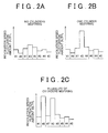
- FIG. 2A shows an example of the revolution speed fluctuation pattern of the cylinders #1 to #8 when none of the cylinders are misfiring. As shown in FIG. 2A , although it varies somewhat, the revolution speed fluctuation amount DLTFL of each cylinder #1 to #8 at this time is small.
- FIG. 2B shows an example of a revolution speed fluctuation pattern when a single cylinder is misfiring, i.e., when misfiring occurs in only one of the cylinders.
- the revolution speed fluctuation amount DLTFL of the misfiring cylinder i.e., the third cylinder #3 in FIG. 2B
- the revolution speed fluctuation amounts DLTFL of the other cylinders is much larger than the revolution speed fluctuation amounts DLTFL of the other cylinders.
- FIG. 2C shows an example of a revolution speed fluctuation pattern when a plurality of cylinders is misfiring.
- the revolution speed fluctuation amounts DLTFL of the misfiring cylinders i.e., the third cylinder #3 and the eighth cylinder #8 in FIG. 2C
- the revolution speed fluctuation pattern when a plurality of cylinders is misfiring may change in ways other than that shown in FIG. 2C depending on the combination of misfiring cylinders.
- the ECU 23 determines whether none, one, or a plurality of cylinders is misfiring by the revolution speed fluctuation pattern of the cylinders #1 to #8. That is, if all of the revolution speed fluctuation amounts DLTFL of the cylinders #1 to #8 are small, the ECU 23 determines that none of the cylinders are misfiring. If the revolution speed fluctuation amount DLTFL of a single cylinder is much higher than the rest, the ECU 23 determines that one of the cylinders is misfiring.
- the ECU 23 determines that a plurality of cylinders is misfiring.
- the ECU 23 determines that only one cylinder is misfiring, the ECU 23 then identifies the misfiring cylinder in the following manner. That is, the ECU 23 counts the number of times the revolution speed fluctuation amount DLTFL exceeds a specified misfire determining value LVMF for each cylinder during a specified number of cycles, and identifies the cylinder for which the number of times counted is greatest as the misfiring cylinder. In this case, the misfiring cylinder is identified after counting is performed during a period of 100 combustion cycles in each cylinder #1 to #8, i.e., during a period of 100 revolutions (rev) of the crankshaft 21.
- the ECU 23 determines that a plurality of cylinders is misfiring, the ECU 23 identifies the misfiring cylinders in the following manner.
- simultaneous misfiring in three or more cylinders can be stochastically ignored so at this time it is considered that two cylinders are misfiring.
- the two misfiring cylinders are identified by obtaining an integrated value of the revolution speed fluctuation amount DLTFL in a specified number of cycles for each cylinder and determining the magnitude of the revolution speed fluctuation of each cylinder by the amount of that integrated value. More specifically, for each cylinder #1 to #8, the ECU 23 calculates the integrated value of the revolution speed fluctuation amount DLTFL in 100 combustion cycles and identifies the two cylinders with the largest integrated values as the misfiring cylinders.
- FIG. 3 shows an example of change in the revolution speed fluctuation amount DLTFL of each cylinder #1 to #8 when two cylinders are misfiring.
- the revolution speed fluctuation amounts DLTFL of those cylinders increase.
- FIG. 4 is a flowchart illustrating a misfiring cylinder identifying routine employed in this example embodiment. This routine is executed by the ECU 23 when it is confirmed that a cylinder(s) is misfiring.
- the ECU 23 When the routine starts, the ECU 23 first determines in step S10 whether a single cylinder is misfiring or a plurality of cylinders is misfiring based on the revolution speed fluctuation pattern in the manner described above. If it is determined that a single cylinder is misfiring, then in steps S20 and S30 the ECU 23 adds up (integrates) misfire counter values for each cylinder, i.e., counts the number of times the revolution speed fluctuation amount DLTFL exceeds the specified misfire determining value LVMF for each cylinder, during 200 revolutions (rev) of the crankshaft 21. Then in step S40, the ECU 23 identifies the misfiring cylinder based on the results from those steps. More specifically, the ECU 23 at this time identifies the cylinder with the highest misfire counter value as the misfiring cylinder. Then in step S80, the ECU 23 stops supplying fuel to the identified misfiring cylinder and this cycle of the routine ends.
- step S10 determines in step S10
- step S10 If, on the other hand, it is determined in step S10 that a plurality of cylinders is misfiring, then in steps S50 and S60 the ECU 23 adds up the revolution speed fluctuation amounts DLTFL of each cylinder #1 to #8 during 200 revolutions (rev) of the crankshaft 21. That is, the ECU 23 at this time calculates the integrated value of the revolution speed fluctuation amount DLTFL during 200 revolutions of the crankshaft 21 for each cylinder.
- step S70 the ECU 23 identifies the two cylinders with the highest calculated integrated values as the misfiring cylinders. Then in step S80, the ECU 23 stops supplying fuel to the identified misfiring cylinders and this cycle of the routine ends.
- the process performed by the ECU 23 in step S10 of the misfiring cylinder identifying routine may be regarded as a process performed by "determining means for determining whether a plurality of cylinders is misfiring" of the invention.
- the processes performed by the ECU 23 in steps S50 to S70 of the misfiring cylinder identifying routine may be regarded as processes performed by "identifying means for identifying the two cylinders having the largest revolution speed fluctuation amounts as the misfiring cylinders when it is determined that a plurality of cylinders is misfiring" of the invention.
- the ECU 23 determines whether a single cylinder is misfiring or a plurality of cylinders is misfiring. When it is determined that a plurality of cylinders is misfiring, the ECU 23 identifies the misfiring cylinders in the order of the revolution speed fluctuation from largest. That is, in this example embodiment, when identifying the misfiring cylinders, the ECU 23 first only determines whether a single cylinder is misfiring or a plurality of cylinders is misfiring.
- the determination as to whether a single cylinder is misfiring or a plurality of cylinders is misfiring can be made relatively easily if not identify the misfiring cylinder(s). If it is determined that a plurality of cylinders is misfiring, simultaneous misfiring in three or more cylinders can be stochastically ignored so it is considered that two cylinders are misfiring. Once it is determined that two cylinders are misfiring, the misfiring cylinders can be easily identified by the magnitude of the revolution speed fluctuation of each cylinder.
- this example embodiment by first determining whether only one cylinder is misfiring or a plurality of cylinders is misfiring and then identifying the misfiring cylinder(s), i.e., by performing these steps separately in this way, it is possible to identify a misfiring cylinder(s) using only simple logic, regardless of whether a single cylinder is misfiring or two cylinders are misfiring. Therefore this example embodiment makes it possible to identify a misfiring cylinder(s) in a multiple cylinder internal combustion engine using only relatively simple logic.
- the ECU 23 obtains the integral value of the revolution speed fluctuation amount in a specified number of cycles and determines the magnitude of the revolution speed fluctuation amount of each cylinder by the size of that integrated value. Accordingly, the misfiring cylinders when a plurality of cylinders is misfiring can be identified using the simple logic of obtaining the integrated values of the revolution speed fluctuation amounts and identifying the two cylinders with the largest integrated values as the misfiring cylinders.
- the ECU 23 if it is determined that only one cylinder is misfiring, the ECU 23 counts the number of times the revolution speed fluctuation amount has exceeded the specified misfire determining value LVMF for each cylinder during the specified number of cycles, and identifies the cylinder with the highest number of times counted as the misfiring cylinder. Therefore, the misfiring cylinder when only one cylinder is misfiring can be identified with simple logic.
- the integrated value of the revolution speed fluctuation amount DLTFL in a specified number of cycles is obtained for each cylinder. Then the magnitude of the revolution speed fluctuation of each cylinder is determined by the size of the integrated values, and the two cylinders with the largest integrated value are identified as the misfiring cylinders. In the second example embodiment, the number of times that the revolution speed fluctuation amount DLTFL exceeds the specified misfire determining value LVMF is counted for each cylinder, and the magnitude of the revolution speed fluctuation of each cylinder is determined by the number of times counted. The two cylinders having the largest magnitudes are identified as the misfiring cylinders.
- a misfire counter is set for each cylinder and it is determined for each combustion cycle whether the revolution speed fluctuation amount DLTFL exceeds the misfire determining value LVMF.
- the revolution speed fluctuation amount DLTFL exceeds the misfire determining value LVMF
- the value of the misfire counter for that cylinder increases by 1.
- FIG. 5 is a graph showing an example of a shift in the revolution speed fluctuation amount DLTFL of the cylinders #1 to #8 when two cylinders are misfiring.
- the revolution speed fluctuation amounts DLTFL of those misfiring cylinders increase.
- the values of the misfire counters of those cylinders increase incrementally each time the values of the revolution speed fluctuation amounts DLTFL exceed the specified misfire determining value LVMF.
- the value of the revolution speed fluctuation amount DLTFL may be equal to or below the misfire determining value LVMF depending on the combustion cycle.
- misfiring may also occur only intermittently.
- FIG. 6 is a flowchart illustrating a misfiring cylinder identifying routine employed in this second example embodiment. This routine is also executed by the ECU 23 when misfiring has been confirmed. Also, the processes of steps S10 to S40 and S80 in this routine are the same as they are in the routine in the first example embodiment shown in FIG. 4 .
- step S10 if it is determined in step S10 that a plurality of cylinders is misfiring, the ECU 23 adds up the misfire counter values in each of the cylinders #1 to #8 during 200 revolutions of the crankshaft 21 in steps S150 and S160. That is, the ECU 23 at this time counts the number of times the revolution speed fluctuation amount DLTFL of each cylinder #1 to #8 exceeds the misfire determining value LVMF during 200 revolutions of the crankshaft 21, and stores that number in a misfire counter for each cylinder.
- step S 170 the ECU 23 identifies the two cylinders that have the largest misfire counter values as the misfiring cylinders, and in step S80 the ECU 23 stops the supply of fuel to the identified misfiring cylinders. Then this cycle of the routine ends.
- the process performed by the ECU 23 in step S10 of the misfiring cylinder identifying routine may be regarded as a process performed by "determining means for determining whether a single cylinder is misfiring or a plurality of cylinders is misfiring" of the invention.
- the processes performed by the ECU 23 in steps S 150 to S170 of the misfiring cylinder identifying routine may be regarded as processes performed by "identifying means for identifying the two cylinders in the order of the revolution speed fluctuation from largest when it is determined by the determining means that a plurality of cylinders is misfiring" of the invention.
- the multiple cylinder internal combustion engine misfiring cylinder identifying apparatus yields the following effects in addition to the effects from the first example embodiment described above.
- the ECU 23 counts the number of times the revolution speed fluctuation amount exceeds the specified misfire determining value LVMF for each cylinder during a specified number of cycles, and determines the magnitude of the revolution speed fluctuation of each cylinder from the number of times counted. Accordingly, the misfiring cylinders when a plurality of cylinders is misfiring can be identified using the simple logic of counting the number of times the revolution speed fluctuation amount exceeds the specified misfire determining value LVMF and identifying the two cylinders for which the number of times counted is the largest as the misfiring cylinders.
- the misfiring cylinders are identified while stochastically ignoring simultaneous misfiring in three or more cylinders.
- the misfiring cylinders can also be identified when three or more cylinders are misfiring simultaneously.
- a multiple cylinder internal combustion engine misfiring cylinder identifying apparatus is able to identify the misfiring cylinders not only when one or two cylinders are misfiring, but also when three cylinders are misfiring.
- the number of misfiring cylinders is determined by one of the following two determining methods.
- One method determines the number of misfiring cylinders based on a comparison of the integrated value of the revolution speed fluctuation amount DLTFL of all of the cylinders in a specified number of cycles and a determining value set for each number of misfiring cylinders. As the number of misfiring cylinders increases so too does the revolution speed fluctuation amount of the internal combustion engine. Therefore, the number of misfiring cylinders can be determined based on a comparison of the integrated value of the revolution speed fluctuation amount DLTFL of all of the cylinders in a specified number of cycles and the determining value set for each number of misfiring cylinders.
- the integrated value of the revolution speed fluctuation amount DLTFL of all of the cylinders in a specified number of cycles is equal to or greater than a first determining value but below a second determining value (which is greater than the first determining value), it is determined that only one cylinder is misfiring. If that integrated value is equal to or greater than the second determining value but below a third determining value (which is greater than the second determining value), it is determined that two cylinders are misfiring. If that integrated value is equal to or greater than the third determining value, it is determined that three cylinders are misfiring.
- another method determines the number of misfiring cylinders based on the fuel injection quantity and/or the intake air amount when the multiple cylinder internal combustion engine is operating under specified operating conditions. If the number of misfiring cylinders increases, more torque per unit cylinder is needed to obtain a constant engine output so the fuel injection quantity and the intake air amount when the multiple cylinder internal combustion engine is operated under specific operating conditions increase each time the number of misfiring cylinders increases. As a result, it is possible to determine the number of misfiring cylinders from the fuel injection quantity and/or the intake air amount under those conditions.
- the number of misfiring cylinders can be determined based on the fuel injection quantity and/or the intake air amount when the engine is idling, during which time feedback control is performed with respect to the intake air amount and the fuel injection quantity in order to keep the engine speed at a specified idle speed when generally no load is being applied.
- the number of misfiring cylinders can similarly be determined based on the fuel injection quantity and/or the intake air amount when the vehicle speed is being maintained at a specific vehicle speed by the driver operating the accelerator while a vehicle which uses a multiple cylinder internal combustion engine as the prime mover is running on a flat road.
- the misfiring cylinders can be easily identified based on the integrated value of the revolution speed fluctuation amount DLTFL or the value of the misfire counter as described above. That is, if the number of misfiring cylinders is determined to be "n", then the integrated value of the revolution speed fluctuation amount in a specified number of cycles can be obtained for each cylinder and the "n" number of cylinders with the largest integrated values can be identified as the misfiring cylinders.
- the number of times the revolution speed fluctuation amount exceeds the specified misfire determining value LVMF can be counted for each cylinder, and the "n" number of cylinders with the most number of times counted can be identified as the misfiring cylinders.
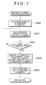
- FIG. 7 is a flowchart illustrating an example of a misfiring cylinder identifying routine employed in this third example embodiment. This routine is executed by the ECU 23 when misfiring has been confirmed. Incidentally, the flowchart in FIG. 7 shows the sequence of steps when identifying the misfiring cylinder(s) using the misfire counter. Alternatively, however, the misfiring cylinder(s) may also be identified using the integrated value of the revolution speed fluctuation amount DLTFL for each cylinder as described above.
- step S200 the ECU 23 determines the number of misfiring cylinders n according to one of the two methods described above. Once the number of misfiring cylinders n has been determined, the ECU 23 then adds up the misfire counter values for each cylinder #1 to #8 during 200 revolutions (rev) of the crankshaft 21 in steps S210 and S220. That is, the ECU 23 at this time counts the number of times the revolution speed fluctuation amount DLTFL of each cylinder #1 to #8 exceeds the misfire determining value LVMF for each cylinder and stores that number in the misfire counter for each cylinder.
- step S230 the ECU 23 identifies the "n" number of cylinders with the largest misfire counter values as the misfiring cylinders and in step S240 the ECU 23 stops the supply of fuel to the identified misfiring cylinders, after which this cycle of the routine ends.
- the process performed by the ECU 23 in step S200 of the misfiring cylinder identifying routine may be regarded as a process performed by "determining means for determining the number of misfiring cylinders" of the invention.
- the processes performed by the ECU 23 in steps S210 to S230 of the misfiring cylinder identifying routine may be regarded as processes performed by "identifying means for identifying the misfiring cylinders the misfiring cylinders corresponding to the number of misfiring cylinders in the order of the revolution speed fluctuation from largest when it is determined that a plurality of cylinders is misfiring" of the invention.
- the ECU 23 determines the number of misfiring cylinders and identifies the misfiring cylinders corresponding to the number of misfiring cylinders in the order of the revolution speed fluctuation from largest. That is, when identifying the misfiring cylinders, the ECU 23 first only determines the number of cylinders that are misfiring, i.e., the number of misfiring cylinders. The number of misfiring cylinders can be determined relatively easily if not identifying the misfiring cylinder(s). Once the number of misfiring cylinders has been determined, the misfiring cylinders can be identified using simple logic.
- this third example embodiment by first determining the number of misfiring cylinders and then identifying those misfiring cylinders, i.e., by performing these steps separately in this way, it is possible to identify misfiring cylinders using only simple logic, regardless of whether only one cylinder is misfiring or a plurality of cylinders is misfiring. Therefore this third example embodiment makes it possible to identify a misfiring cylinder(s) in a multiple cylinder internal combustion engine using only relatively simple logic.
- the ECU 23 counts the number of times the revolution speed fluctuation amount exceeds the specified misfire determining value LVMF during a specified number of cycles with a misfire counter set for each cylinder. Then the ECU 23 determines the magnitude of the revolution speed fluctuation of each cylinder #1 to #8 from the number of times counted and identifies the cylinders of that number n (i.e., the number of misfiring cylinders n) in the order of the revolution speed fluctuation from largest, or more specifically, with the highest the misfire counter values. Therefore, the misfiring cylinders can be identified with simple logic after the number of misfiring cylinders n has been determined.
- the misfiring cylinders can be identified by obtaining the integrated value of the revolution speed fluctuation amount DLTFL in a specified number of cycles for each cylinder, and determining the magnitude of the revolution speed fluctuation of each cylinder from the size of that integrated value.
- cylinders of the number of misfiring cylinders n having the highest integrated values can be identified as the misfiring cylinders.
- the misfiring cylinders can be identified using simple logic after the number of misfiring cylinders n has been determined.
- the number of misfiring cylinders n is determined either based on a comparison between the integrated values of the revolution speed fluctuation amounts of all of the cylinders in a specified number of cycles and the determining value set for each number of misfiring cylinders, or the fuel injection quantity and/or the intake air amount when the multiple cylinder internal combustion engine is operating under specified operating conditions. Accordingly, the number of misfiring cylinders n can be appropriately determined.
- the example embodiments described above may also be modified as follows.
- the number of misfiring cylinders n is determined by one of the two methods described above.
- the number of misfiring cylinders n may also be determined by a method other than the two methods described above.
- the determination as to whether one or a plurality of cylinders is misfiring is made based on the revolution speed fluctuation pattern.
- that determination can also be made using that logic. That is, as long as there is logic that makes it possible to determine whether a misfire is occurring in only one cylinder, it is possible to employ appropriate logic as logic related to determining whether a single cylinder is misfiring or a plurality of cylinders is misfiring.
- the misfiring cylinders are identified by determining the magnitude of the revolution speed fluctuation of each cylinder #1 to #8 from the integrated value of the revolution speed fluctuation amount DLTFL or the misfire counter value.
- the misfiring cylinders may instead be identified based on the magnitude of the revolution speed fluctuation ascertained according to such logic.
- the revolution speed fluctuation amount DLTFL of each cylinder #1 to #8 is calculated according to Equation 1 above.
- other appropriate logic related to calculating the revolution speed fluctuation amount DLTFL can also be used. That is, if there is separate calculating logic that is suitable for calculating the revolution speed fluctuation amount DLTFL, the revolution speed fluctuation amount DLTFL may also be calculated using that logic instead of according to Equation 1 described above.
- the invention is applied to a misfiring cylinder identifying apparatus of a V-type eight-cylinder internal combustion engine.
- the invention may similarly be applied to a misfiring cylinder identifying apparatus of different type multiple cylinder internal combustion engine.
- the invention is applied to a spark ignition multiple cylinder internal combustion engine in which fuel is ignited by spark discharge using the spark plug 19.
- the invention may similarly be applied as an apparatus that identifies a misfiring cylinder(s) in a compression ignition multiple cylinder internal combustion engine.
Landscapes
- Chemical & Material Sciences (AREA)
- Engineering & Computer Science (AREA)
- Combustion & Propulsion (AREA)
- Physics & Mathematics (AREA)
- General Physics & Mathematics (AREA)
- Combined Controls Of Internal Combustion Engines (AREA)
- Electrical Control Of Air Or Fuel Supplied To Internal-Combustion Engine (AREA)
Applications Claiming Priority (1)
| Application Number | Priority Date | Filing Date | Title |
|---|---|---|---|
| JP2007278853A JP4483927B2 (ja) | 2007-10-26 | 2007-10-26 | 多気筒内燃機関の失火気筒特定装置 |
Publications (3)
| Publication Number | Publication Date |
|---|---|
| EP2053376A2 true EP2053376A2 (de) | 2009-04-29 |
| EP2053376A3 EP2053376A3 (de) | 2014-08-27 |
| EP2053376B1 EP2053376B1 (de) | 2016-06-29 |
Family
ID=40282485
Family Applications (1)
| Application Number | Title | Priority Date | Filing Date |
|---|---|---|---|
| EP08167431.9A Not-in-force EP2053376B1 (de) | 2007-10-26 | 2008-10-23 | Fehlzündungszylinder-Identifizierungsvorrichtung für einen mehrzylindrischen Verbrennungsmotor und Verfahren zur Identifizierung eines Fehlzündungszylinders |
Country Status (3)
| Country | Link |
|---|---|
| US (1) | US7958778B2 (de) |
| EP (1) | EP2053376B1 (de) |
| JP (1) | JP4483927B2 (de) |
Families Citing this family (9)
| Publication number | Priority date | Publication date | Assignee | Title |
|---|---|---|---|---|
| DE102010001534B4 (de) * | 2009-02-17 | 2022-03-24 | Robert Bosch Gmbh | Verfahren zur Bestimmung mindestens eines aussetzenden Zylinders einer Brennkraftmaschine, Steuergerät und Kraftfahrzeugtriebstrang |
| DE102009018081B4 (de) * | 2009-04-20 | 2011-01-13 | Continental Automotive Gmbh | Verfahren und Vorrichtung zum Betreiben einer Brennkraftmaschine |
| JP2012026365A (ja) | 2010-07-23 | 2012-02-09 | Aisin Seiki Co Ltd | 複数気筒4サイクルエンジンの失火判定装置 |
| DE102011108307B4 (de) * | 2011-07-21 | 2019-07-18 | Volkswagen Aktiengesellschaft | Verfahren und Vorrichtung zum Bestimmen eines Auftretens einer Vorentflammung |
| JP6071370B2 (ja) * | 2012-09-21 | 2017-02-01 | 日立オートモティブシステムズ株式会社 | 内燃機関の制御装置 |
| SE1850053A1 (en) * | 2015-07-22 | 2018-01-18 | Wallbro Llc | Engine control strategy |
| JP7392672B2 (ja) * | 2021-01-29 | 2023-12-06 | トヨタ自動車株式会社 | 内燃機関の失火検出装置 |
| CN112963253A (zh) * | 2021-03-23 | 2021-06-15 | 潍柴动力股份有限公司 | 一种发动机点火缸的控制方法及装置 |
| JP7604432B2 (ja) * | 2022-09-30 | 2024-12-23 | 本田技研工業株式会社 | 内燃機関の失火判定装置 |
Citations (3)
| Publication number | Priority date | Publication date | Assignee | Title |
|---|---|---|---|---|
| JPH0518311A (ja) | 1991-07-12 | 1993-01-26 | Toyota Motor Corp | 異常検出装置 |
| JPH10318033A (ja) | 1997-05-23 | 1998-12-02 | Toyota Motor Corp | 多気筒内燃機関の失火検出装置 |
| JP2003343340A (ja) | 2002-05-31 | 2003-12-03 | Toyota Motor Corp | 内燃機関の失火検出装置 |
Family Cites Families (16)
| Publication number | Priority date | Publication date | Assignee | Title |
|---|---|---|---|---|
| US5699252A (en) * | 1992-03-30 | 1997-12-16 | Purdue Research Foundation | Error correction in measures of speed, acceleration, misfire detection and roughness |
| US5808186A (en) * | 1992-06-09 | 1998-09-15 | Mitsubishi Jidosha Kogyo Kabushiki Kaisha | Method for detecting misfire by fluctuation in crankshaft rotation |
| JPH07119532A (ja) | 1993-10-19 | 1995-05-09 | Unisia Jecs Corp | 内燃機関の失火検出装置 |
| JP3231947B2 (ja) | 1994-07-19 | 2001-11-26 | 三菱自動車工業株式会社 | 内燃機関の燃焼異常検出方法 |
| US6062071A (en) * | 1995-11-30 | 2000-05-16 | Siemens Aktiengesellschaft | Method for detecting combustion misfires in an internal combustion engine |
| JPH10148153A (ja) | 1996-11-20 | 1998-06-02 | Fuji Heavy Ind Ltd | エンジンの失火診断装置 |
| JP3915335B2 (ja) | 1999-08-30 | 2007-05-16 | 株式会社デンソー | ハイブリッド車両の制御装置 |
| JP2005337021A (ja) | 2004-05-24 | 2005-12-08 | Suzuki Motor Corp | 多気筒エンジンの失火検出装置 |
| JP4525538B2 (ja) * | 2005-02-24 | 2010-08-18 | トヨタ自動車株式会社 | 内燃機関の失火判定装置および失火判定方法 |
| JP4353130B2 (ja) * | 2005-04-20 | 2009-10-28 | トヨタ自動車株式会社 | 内燃機関の失火検出装置 |
| JP4509986B2 (ja) * | 2005-12-27 | 2010-07-21 | 本田技研工業株式会社 | 内燃機関の失火検出装置 |
| JP4492549B2 (ja) * | 2006-01-27 | 2010-06-30 | トヨタ自動車株式会社 | 失火判定装置、ハイブリッド自動車及び失火判定方法 |
| JP4442568B2 (ja) | 2006-01-27 | 2010-03-31 | トヨタ自動車株式会社 | 内燃機関の失火判定装置および失火判定方法 |
| JP4279866B2 (ja) * | 2006-10-30 | 2009-06-17 | 本田技研工業株式会社 | 内燃機関の失火検出装置 |
| JP4339347B2 (ja) * | 2006-10-30 | 2009-10-07 | 本田技研工業株式会社 | 内燃機関のクランク角速度検出装置 |
| JP4438858B2 (ja) * | 2007-12-12 | 2010-03-24 | トヨタ自動車株式会社 | 内燃機関の失火判定装置および車両並びにねじれ要素の剛性推定装置,内燃機関の失火判定方法,ねじれ要素の剛性推定方法 |
-
2007
- 2007-10-26 JP JP2007278853A patent/JP4483927B2/ja not_active Expired - Fee Related
-
2008
- 2008-10-22 US US12/255,717 patent/US7958778B2/en not_active Expired - Fee Related
- 2008-10-23 EP EP08167431.9A patent/EP2053376B1/de not_active Not-in-force
Patent Citations (3)
| Publication number | Priority date | Publication date | Assignee | Title |
|---|---|---|---|---|
| JPH0518311A (ja) | 1991-07-12 | 1993-01-26 | Toyota Motor Corp | 異常検出装置 |
| JPH10318033A (ja) | 1997-05-23 | 1998-12-02 | Toyota Motor Corp | 多気筒内燃機関の失火検出装置 |
| JP2003343340A (ja) | 2002-05-31 | 2003-12-03 | Toyota Motor Corp | 内燃機関の失火検出装置 |
Also Published As
| Publication number | Publication date |
|---|---|
| US7958778B2 (en) | 2011-06-14 |
| EP2053376A3 (de) | 2014-08-27 |
| EP2053376B1 (de) | 2016-06-29 |
| JP4483927B2 (ja) | 2010-06-16 |
| JP2009108690A (ja) | 2009-05-21 |
| US20090107224A1 (en) | 2009-04-30 |
Similar Documents
| Publication | Publication Date | Title |
|---|---|---|
| EP2053376B1 (de) | Fehlzündungszylinder-Identifizierungsvorrichtung für einen mehrzylindrischen Verbrennungsmotor und Verfahren zur Identifizierung eines Fehlzündungszylinders | |
| CN102016270B (zh) | 用于内燃发动机的失火探测设备 | |
| US8601862B1 (en) | System and method for detecting misfire based on a firing pattern of an engine and engine torque | |
| US5690073A (en) | Fuel injection control device of a multi-cylinder engine | |
| JP6353333B2 (ja) | 失火判定装置 | |
| US9097196B2 (en) | Stochastic pre-ignition detection systems and methods | |
| EP1873383B1 (de) | Zündausfallerfassungsvorrichtung für verbrennungsmotor | |
| US12163495B2 (en) | Control apparatus for internal combustion engine | |
| US5447061A (en) | Misfire detection method for engine | |
| US6415656B1 (en) | Onboard diagnostic misfire detection monitor for internal combustion engines | |
| US6823849B2 (en) | Fuel injection system and control method for internal combustion engine starting time | |
| US6732042B2 (en) | Apparatus and method for detecting misfire in internal combustion engine | |
| CN101454557B (zh) | 用于运行内燃机的方法和装置 | |
| US6801848B1 (en) | Methods and apparatus for sensing misfire in an internal combustion engine | |
| US10094316B2 (en) | Control apparatus for internal combustion engine | |
| US12163858B2 (en) | Misfire determination device for internal combustion engine | |
| JP6742470B1 (ja) | 内燃機関の制御装置 | |
| US20060293830A1 (en) | Apparatus and method for judging a piston position in an engine | |
| JP2013024062A (ja) | エンジンの気筒判定装置 | |
| JP2005180356A (ja) | クランク角センサの補正装置および補正方法 | |
| JP2016098690A (ja) | 内燃機関の失火判定装置 | |
| CN121702746A (zh) | 气缸失火诊断方法、装置、设备及计算机可读存储介质 | |
| JP2004176563A (ja) | 多気筒内燃機関の失火検出装置 |
Legal Events
| Date | Code | Title | Description |
|---|---|---|---|
| PUAI | Public reference made under article 153(3) epc to a published international application that has entered the european phase |
Free format text: ORIGINAL CODE: 0009012 |
|
| 17P | Request for examination filed |
Effective date: 20081023 |
|
| AK | Designated contracting states |
Kind code of ref document: A2 Designated state(s): AT BE BG CH CY CZ DE DK EE ES FI FR GB GR HR HU IE IS IT LI LT LU LV MC MT NL NO PL PT RO SE SI SK TR |
|
| AX | Request for extension of the european patent |
Extension state: AL BA MK RS |
|
| RAP1 | Party data changed (applicant data changed or rights of an application transferred) |
Owner name: TOYOTA JIDOSHA KABUSHIKI KAISHA |
|
| PUAL | Search report despatched |
Free format text: ORIGINAL CODE: 0009013 |
|
| AK | Designated contracting states |
Kind code of ref document: A3 Designated state(s): AT BE BG CH CY CZ DE DK EE ES FI FR GB GR HR HU IE IS IT LI LT LU LV MC MT NL NO PL PT RO SE SI SK TR |
|
| AX | Request for extension of the european patent |
Extension state: AL BA MK RS |
|
| RIC1 | Information provided on ipc code assigned before grant |
Ipc: G01M 15/11 20060101AFI20140718BHEP |
|
| AKX | Designation fees paid |
Designated state(s): DE FR GB |
|
| AXX | Extension fees paid |
Extension state: BA Extension state: MK Extension state: RS Extension state: AL |
|
| GRAP | Despatch of communication of intention to grant a patent |
Free format text: ORIGINAL CODE: EPIDOSNIGR1 |
|
| INTG | Intention to grant announced |
Effective date: 20151216 |
|
| GRAS | Grant fee paid |
Free format text: ORIGINAL CODE: EPIDOSNIGR3 |
|
| GRAR | Information related to intention to grant a patent recorded |
Free format text: ORIGINAL CODE: EPIDOSNIGR71 |
|
| GRAA | (expected) grant |
Free format text: ORIGINAL CODE: 0009210 |
|
| AK | Designated contracting states |
Kind code of ref document: B1 Designated state(s): DE FR GB |
|
| INTG | Intention to grant announced |
Effective date: 20160523 |
|
| REG | Reference to a national code |
Ref country code: GB Ref legal event code: FG4D |
|
| REG | Reference to a national code |
Ref country code: DE Ref legal event code: R096 Ref document number: 602008044863 Country of ref document: DE |
|
| REG | Reference to a national code |
Ref country code: DE Ref legal event code: R097 Ref document number: 602008044863 Country of ref document: DE |
|
| PLBE | No opposition filed within time limit |
Free format text: ORIGINAL CODE: 0009261 |
|
| STAA | Information on the status of an ep patent application or granted ep patent |
Free format text: STATUS: NO OPPOSITION FILED WITHIN TIME LIMIT |
|
| 26N | No opposition filed |
Effective date: 20170330 |
|
| GBPC | Gb: european patent ceased through non-payment of renewal fee |
Effective date: 20161023 |
|
| REG | Reference to a national code |
Ref country code: DE Ref legal event code: R084 Ref document number: 602008044863 Country of ref document: DE |
|
| REG | Reference to a national code |
Ref country code: FR Ref legal event code: ST Effective date: 20170630 |
|
| PG25 | Lapsed in a contracting state [announced via postgrant information from national office to epo] |
Ref country code: FR Free format text: LAPSE BECAUSE OF NON-PAYMENT OF DUE FEES Effective date: 20161102 Ref country code: GB Free format text: LAPSE BECAUSE OF NON-PAYMENT OF DUE FEES Effective date: 20161023 |
|
| PGFP | Annual fee paid to national office [announced via postgrant information from national office to epo] |
Ref country code: DE Payment date: 20210914 Year of fee payment: 14 |
|
| REG | Reference to a national code |
Ref country code: DE Ref legal event code: R119 Ref document number: 602008044863 Country of ref document: DE |
|
| PG25 | Lapsed in a contracting state [announced via postgrant information from national office to epo] |
Ref country code: DE Free format text: LAPSE BECAUSE OF NON-PAYMENT OF DUE FEES Effective date: 20230503 |