EP2052948A2 - Elektrische Servolenkung - Google Patents
Elektrische Servolenkung Download PDFInfo
- Publication number
- EP2052948A2 EP2052948A2 EP08167161A EP08167161A EP2052948A2 EP 2052948 A2 EP2052948 A2 EP 2052948A2 EP 08167161 A EP08167161 A EP 08167161A EP 08167161 A EP08167161 A EP 08167161A EP 2052948 A2 EP2052948 A2 EP 2052948A2
- Authority
- EP
- European Patent Office
- Prior art keywords
- current
- phase
- phases
- controller
- value
- Prior art date
- Legal status (The legal status is an assumption and is not a legal conclusion. Google has not performed a legal analysis and makes no representation as to the accuracy of the status listed.)
- Granted
Links
Images






Classifications
-
- B—PERFORMING OPERATIONS; TRANSPORTING
- B62—LAND VEHICLES FOR TRAVELLING OTHERWISE THAN ON RAILS
- B62D—MOTOR VEHICLES; TRAILERS
- B62D5/00—Power-assisted or power-driven steering
- B62D5/04—Power-assisted or power-driven steering electrical, e.g. using an electric servo-motor connected to, or forming part of, the steering gear
- B62D5/0457—Power-assisted or power-driven steering electrical, e.g. using an electric servo-motor connected to, or forming part of, the steering gear characterised by control features of the drive means as such
- B62D5/0481—Power-assisted or power-driven steering electrical, e.g. using an electric servo-motor connected to, or forming part of, the steering gear characterised by control features of the drive means as such monitoring the steering system, e.g. failures
- B62D5/0484—Power-assisted or power-driven steering electrical, e.g. using an electric servo-motor connected to, or forming part of, the steering gear characterised by control features of the drive means as such monitoring the steering system, e.g. failures for reaction to failures, e.g. limp home
-
- B—PERFORMING OPERATIONS; TRANSPORTING
- B62—LAND VEHICLES FOR TRAVELLING OTHERWISE THAN ON RAILS
- B62D—MOTOR VEHICLES; TRAILERS
- B62D5/00—Power-assisted or power-driven steering
- B62D5/04—Power-assisted or power-driven steering electrical, e.g. using an electric servo-motor connected to, or forming part of, the steering gear
- B62D5/0457—Power-assisted or power-driven steering electrical, e.g. using an electric servo-motor connected to, or forming part of, the steering gear characterised by control features of the drive means as such
-
- B—PERFORMING OPERATIONS; TRANSPORTING
- B62—LAND VEHICLES FOR TRAVELLING OTHERWISE THAN ON RAILS
- B62D—MOTOR VEHICLES; TRAILERS
- B62D5/00—Power-assisted or power-driven steering
- B62D5/04—Power-assisted or power-driven steering electrical, e.g. using an electric servo-motor connected to, or forming part of, the steering gear
- B62D5/0457—Power-assisted or power-driven steering electrical, e.g. using an electric servo-motor connected to, or forming part of, the steering gear characterised by control features of the drive means as such
- B62D5/0481—Power-assisted or power-driven steering electrical, e.g. using an electric servo-motor connected to, or forming part of, the steering gear characterised by control features of the drive means as such monitoring the steering system, e.g. failures
-
- G—PHYSICS
- G01—MEASURING; TESTING
- G01R—MEASURING ELECTRIC VARIABLES; MEASURING MAGNETIC VARIABLES
- G01R31/00—Arrangements for testing electric properties; Arrangements for locating electric faults; Arrangements for electrical testing characterised by what is being tested not provided for elsewhere
- G01R31/005—Testing of electric installations on transport means
- G01R31/006—Testing of electric installations on transport means on road vehicles, e.g. automobiles or trucks
-
- G—PHYSICS
- G01—MEASURING; TESTING
- G01R—MEASURING ELECTRIC VARIABLES; MEASURING MAGNETIC VARIABLES
- G01R31/00—Arrangements for testing electric properties; Arrangements for locating electric faults; Arrangements for electrical testing characterised by what is being tested not provided for elsewhere
- G01R31/327—Testing of circuit interrupters, switches or circuit-breakers
- G01R31/3277—Testing of circuit interrupters, switches or circuit-breakers of low voltage devices, e.g. domestic or industrial devices, such as motor protections, relays, rotation switches
- G01R31/3278—Testing of circuit interrupters, switches or circuit-breakers of low voltage devices, e.g. domestic or industrial devices, such as motor protections, relays, rotation switches of relays, solenoids or reed switches
Definitions
- the present invention relates to an electric power steering apparatus in which a three-phase brushless motor is used to generate a steering assist force.
- the present invention relates to the configuration of the control circuit thereof.
- An electric power steering apparatus is an apparatus in which a motor is used to generate a steering assist force in accordance with a steering torque caused in a steering shaft.
- the motor is generally a three-phase brushless motor.
- the motor is mainly controlled by a CPU and an electronic circuit.
- a circuit configuration has been used in which a feeding current path to the motor includes a relay contact so that the contact is opened when the CPU or electronic circuit has abnormality to securely stop the feeding to the motor (see Japanese Published Unexamined Patent Application JP-A-2006-182 166 for example).
- the above contact must be closed when the electric power steering apparatus operates normally and must be conductive with a favorable electrical conductivity.
- the surface of the contact is oxidized for example to have thereon an insulating film or when dusts existing at the periphery of the contact or fine abrasion powder of the relay itself for example are attached to the surface of the contact, these foreign matters cause an increase in the contact resistance of the contact, thus reducing the electrical conductivity.
- the reduced electrical conductivity causes an adverse influence on the motor control.
- a function is required to check whether the contact has a favorable electrical conductivity or not when the electric power steering apparatus is started.
- Another function is also required, in addition to the mere check function, to solve or reduce a minor or temporary reduction in the electrical conductivity to recover a favorable electrical conductivity.
- an objective of the present invention to provide an electric power steering apparatus having a configuration in which relay contacts are inserted to at least current paths of two phases among current paths of three phases for supplying electric power to a three-phase brushless motor so that the conduction check of the contacts is securely performed and an improved function is provided to remove foreign matters on the surface of the contact to recover a favorable electrical conductivity.
- an electric power steering apparatus using a three-phase brushless motor to generate a steering assist force comprises:
- the contacts are inserted only to current paths of two phases among the current paths of the three phases, respectively, and "the current path of any one phase" may be a current path of one phase having no contact inserted.
- a waste can be excluded that is caused by the current for investigating electrical conductivity in a current path including no contact.
- the controller preferably determines the positive and negative signs of currents flowing in the respective current paths of the two phases such that a rotation angle of the rotor from the current position is minimum.
- the status in which no current flows in a current path of a phase including no contact and currents having an identical absolute value and different positive and negative signs flow in the current paths of the other two phases appears whenever the electric angle of 180° is reached.
- the current position of the rotor is not fixed.
- the positive and negative signs of the current determined so as to achieve the minimum rotation angle from the current position can allow the rotor at an arbitrary current position to be positioned at 90° to the nearest electric angle at maximum, thus limiting the rotation angle of the rotor.
- the above electric power steering apparatus may include a reducer and a value obtained by multiplying a reduction ratio with a motor pole number may be 90 or more.
- the reduction ratio to the motor pole number so as to satisfy the conditions as described above, even when the rotor is rotated with the electric angle of 90° at maximum, the rotation of the steering wheel can be limited to 2° or less. The rotation of 2° or less is difficultly noticed by the driver. Specifically, even when the steering wheel is slightly rotated due to the conduction check process at the contact, the driver can be suppressed from noticing this to feel uncomfortable.
- the contacts may be inserted to all of the current paths of the three phases, respectively.
- the controller may perform the conduction check process based on two stages among which a first stage is performed by the controller to carry out the conduction check process by using one phase that has an electric angle nearest to the current position of the rotor and that has a current value of 0 on a driving current waveform of the three-phase brushless motor as a current path in which no current flows and a second stage is performed by the controller to carry out the conduction check process by using the other one phase that has an electric angle nearest to the electric angle in the first stage and that has a current value of 0 of the other one phase as a current path in which no current flows.
- the processing of the two stages can investigate the electrical conductivities of all of the contacts inserted to the current paths of the three phases.
- the rotation angle of the rotor can be suppressed to a smaller value because the conduction check process can be performed without being limited by a specific phase and while the three phases being energized at an energization angle that is nearest to the current position of the rotor and at which one phase has a current value of 0. Since the zero point exists at every 60° of an electric angle, the rotation angle of the rotor also can be within the electric angle of 60°.
- the contacts are inserted to all of the current paths of the three phases, respectively.
- the controller performs the conduction check process based on two stages among which a first stage is performed by the controller to carry out the conduction check process by using a first phase as a current path in which no current flows and a second stage is performed by the controller to carry out the conduction check process by using any one phase among a second phase and a third phase as a current path in which no current flows.
- the processing of the two stages can investigate the electrical conductivities of all of the contacts inserted to the current paths of the three phases.
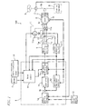
- FIG. 1 is a block diagram illustrating the circuit configuration of an electric power steering apparatus 100 according to the first embodiment of the present invention.
- a controller 1 configured to include a CPU receives a steering torque signal from a torque sensor 2, a vehicle speed signal from a vehicle speed sensor 3, an ON signal from an ignition key (IG key) 4, and an engine revolution signal from an engine revolution sensor 14, respectively.
- the controller 1 drives a three-phase brushless motor (hereinafter called motor) 6 via a motor driving circuit 5.
- motor three-phase brushless motor
- the motor driving circuit 5 includes a known PWM circuit for subjecting a signal sent from the controller 1 to a pulse width modification (PWM) and a three-phase bridge circuit (inverter circuit) and converts electric power supplied from a power source (not shown) to alternate current electric power of three phases of U, V, and W to supply the power to the motor 6 to drive the motor 6.
- PWM pulse width modification
- inverter circuit three-phase bridge circuit
- the motor 6 is connected to a steering axis 8a of a steering apparatus 8 via a reducer 7 and gives a steering assist force to the steering axis 8a.
- the steering axis 8a is connected to a steering wheel (handle) 9 and the torque sensor 2 is provided at the middle therebetween.
- the motor 6 has a rotation angle sensor 10 to send a rotation angle signal of a rotor 6r to the controller 1.
- a contact 11a of a relay 11 is provided at the middle of the current paths L U and L V among the current paths L U , Lv, and L W , respectively.
- the current paths L V and L W have a current sensor 12. Based on the output from the current sensor 12, a current detection circuit 13 detects the current flowing in the current paths L V and L W to detect, based on the current flowing in the current paths L V and L W , the current flowing in the current path L U by calculation to send these detection outputs to the controller 1.
- the current sensor 12 and the current detection circuit 13 constitute a current detector.
- the current sensor 12 may be a shunt resistance, a Hall element, a Hall IC, or a current probe for example.
- the controller 1 includes, as an internal function realized by software, a target current calculator 1a, a comparator 1b, a PI controller 1c, a three-phase/two-phase converter 1d, a two-phase/three-phase converter 1e, and a relay checker 1f.
- the steering torque signal from the torque sensor 2 and the vehicle speed signal from the vehicle speed sensor 3 are input to the target current calculator 1a.
- the signal from the rotation angle sensor 10 is input to the three-phase/two-phase converter 1d and the two-phase/three-phase converter 1e and is also input to the relay checker 1f.
- the output from the current detection circuit 13 is input to the three-phase/two-phase converter 1d and the relay checker 1f.
- the signal from the ignition key 4 and the signal from the engine revolution sensor 14 are input to the relay checker 1f.
- the relay checker 1f gives a control signal to a coil 11c of the relay 11 and the two-phase/three-phase converter 1e.
- the target current calculator 1a calculates, based on the steering torque signal from the torque sensor 2 and the vehicle speed signal from the vehicle speed sensor 3, the target current of the axis d and the axis q to be given to the motor 6.
- the three-phase/two-phase converter 1d uses the rotation angle detected by the rotation angle sensor 10 to convert the currents of the phases U, V, and W to the current of the axis d and the current of the axis q.
- the comparator 1b compares the target current of the axis d and the target current of the axis q with the current of the axis d and the current of the axis q, respectively to carry out a feedback control. Specifically, the control is carried out such that the current of the axis d and the current of the axis q are close to the target current of the axis d and the target current of the axis q, respectively.
- the output from the comparator 1b is subjected to a proportional-integral control by the PI controller 1c and the resultant output is converted by the two-phase/three-phase converter 1e to instruction values of currents of the phases U, V, and W, Based on the instruction values, the motor driving circuit 5 supplies current to the motor 6.
- the relay 11 is always excited based on the instruction from the relay checker 1f and the contacts 11a thereof are closed so long as any abnormality occurs.
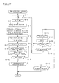
- FIG. 4 when an ignition key 4 is turned ON to subsequently start the engine and an engine revolution signal is input from the engine revolution sensor 14, the engine status shows an in-operation status and the controller 1 performs a starting processing (self initial check) for a predetermined time to subsequently subject the contacts 11a of the relay 11 to the conduction check process.
- the controller 1 (mainly the function of the relay checker 1f) sets an initial value of the count value N to 0 (Step S01).
- the controller 1 excites the relay 11 to close the contacts 11a (Step S02).
- the controller 1 detects the current position of the rotor 6r (Step S03).
- FIG. 2 illustrates driving current waveforms (i.e., field current waveforms (ideal waveforms)) of the three phases (U, V, and W) of the motor 6 in which the horizontal axis shows electric angles (energization angles) and the vertical axis shows current amplitude ratios.
- the rotor 6r is rotated in synchronization with a change in the field current.
- the position of the rotor 6r (electric angle) can have a one-to-one correspondence to the field currents of three phases.
- electric angles of ⁇ 1 (120°) and ⁇ 2 (300°) are found that satisfy the conditions according to which the maximum amount of the currents flows at the phases U and V and no unnecessary current flows at the phase W having no contact 11a.
- the current path L W of the phase W including no contact 11a includes no flow of current and the current paths L U and L V of the other two phases (U and V) includes flows of currents that have an identical absolute value and that have different positive and negative signs (hereinafter merely referred to as sign).
- sign positive and negative signs
- the total of the current values of the three phases of U, V, and W during the driving is 0.
- the other two phases correspond have the flow of currents that have an identical absolute value and that have different signs.
- the controller 1 calculates energization angles ( ⁇ 1 and ⁇ 2 ) at which no current flows in the current path L W of the phase W and currents that have an identical absolute value and that have different signs flow in the current paths L U and L V of the other two phases (U and V) (Step S04). Then, the controller selects, from among the calculated energization angles, the energization angle ( ⁇ 2 ) nearest to the current position (electric angle) of the rotor 6r to set the energization angle as a target electric angle (Step S05).
- Step S06 the controller 1 starts an internal timer (set time T1) (Step S06) to control the motor current (Step S07).
- This control is performed by allowing the relay checker 1f to instruct the two-phase/three-phase converter 1e to control the motor driving circuit 5 so that the current of I[A] flows at the phase U, the current of -I[A] flows at the phase V, and the current of 0[A] flows at the phase W, respectively.
- the currents actually flowing in the current paths L U and L V of the phases U and V are detected by the output from the current detection circuit 13 (Step S08). By the flow of current as described above, the rotor 6r is rotated to the position at the electric angle ⁇ 2 .
- the above current I[A] is on the order of a few amperes for example. By flowing of such high current, the conduction check can be performed securely. Even when the surface of the contact 11a has thereon metal foreign matters or an oxide layer, the metal foreign matters or oxide layer can be fused or can be thermally destroyed and can be removed. This energization of current is continuously performed until the set time T1 is passed (Step S09). When the set time T1 has passed since the start of the flow of the current, the controller 1 determines, with regard to the phase U and the phase V respectively, whether the absolute values of the currents exceed the threshold value or not (Steps S10 and S11).
- the controller 1 determines that each contact 11a has a favorable conduction to complete the conduction check process to subsequently start a normal assist control (Step S12).
- the above threshold value may be set to be lower than the absolute values of the currents I and -I in consideration of a factor that how much the absolute value of the current I flowing at the phases U and V is reduced when any one of the contacts 11a has an increased contact resistance and has an abnormal value.
- Step S 13 When any one of the currents for the phase U and the phase V is equal to or lower than the threshold value on the other hand, whether N reaches a predetermined value or not is determined (Step S 13).
- the value N means the number of execution of the conduction check process (and a foreign matter removal processing) by closing the contacts 11a to pass high current.
- the value N is set to an integer of 2 or more.
- the controller 1 once returns the relay 11 to a not-excited status (Step S14) and increases the value N by one (Step S15) to start the internal timer (set time T2) (Step S16) to wait when the time T2 is passed (Step S17).
- the time T2 is a waiting time for waiting when the relay 11 is not excited and the contacts 11a are securely opened.
- the controller 1 returns to Step S02 to excite the relay 11 again. Thereafter, the same processing is repeated until the value N reaches the predetermined value.
- Step S12 When the repetition of the conduction check process results in the currents of the phase U and the phase V having an absolute value exceeding the threshold value, the controller 1 starts the assist control (Step S12).
- the controller 1 also starts the assist control (Step S12).
- the determination of "YES" in Step 13 also may be followed by a step of providing an alarm display showing that the contact 11a has a defective electrical conductivity.
- the controller 1 increases a motor current limiter value in the motor driving circuit 5.
- the motor driving circuit 5 can cope with the assist control.
- the time chart is as shown in FIG. 5 for example. After the contacts 11a are energized a plurality of times (three times in this case), the controller 1 increases the motor current limiter value in the motor driving circuit 5. As a result, the motor driving circuit 5 can cope with the assist control.
- the above embodiment has performed the conduction check based on the values of the currents of the phase U and the phase V, respectively.
- the conduction check also may be performed based on the current value of any one of the phase U and the phase V.
- the rotation of the rotor 6r results in the rotation of the steering wheel 9 via the reducer 7.
- the rotation angle of the steering wheel 9 is large, the driver may notice the large rotation angle and may feel this uncomfortable.
- An experiment showed that the rotation angle of the steering wheel 9 that is difficultly noticed by the driver is 2° or less.
- the reduction ratio R of the reducer 7 may be selected so that the rotation angle of the steering wheel 9 is 2° or less when the rotor 6r is rotated by the electric angle of 90°.
- the reduction ratio R satisfying the formulae (1) and (2) is 11.25 or more.
- the reduction ratio R satisfying the formulae (3) and (4) is 22.5 or more.
- conditions for providing the rotation angle of the steering wheel 9 of 2° or less are that (motor pole number) ⁇ (reduction ratio) is 90° or more.
- the rotation of the steering wheel 9 can be limited to 2° or less even when the rotor 6r is rotated with an electric angle of 90° at maximum.
- the rotation of the steering wheel 9 of 2° or less is difficultly noticed by the driver. Specifically, even when the steering wheel 9 is slightly rotated due to the conduction check process at the contact 11 a, the driver can be suppressed from noticing this to feel uncomfortable.
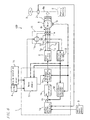
- FIG. 6 is a block diagram illustrating the circuit configuration of the electric power steering apparatus 100 according to the second embodiment of the present invention.
- FIG. 6 has the same circuit configuration as that shown in FIG. 1 except for that the contacts 11 a of the relay 11 are inserted to all of the current paths L U , L V , and L W of the three phases (U, V, and W).
- FIG. 7A and FIG. 7B illustrate driving current waveforms (i.e., field current waveforms) of the three phases (U, V, and W) of the motor 6 in which the horizontal axis shows an electric angle and the vertical axis shows a current amplitude ratio and illustrates the driving current waveforms of the three phases (U, V, and W) of the motor 6 (i.e., field current waveforms (ideal waveforms)).
- driving current waveforms i.e., field current waveforms
- the nearest electric angle among electric angles (hereinafter called a 0 (zero) point) at which the current value of one phase of the three phases of U, V, and W is 0 is the electric angle ⁇ 1 at which the phase U has the current value of 0.
- the energization angle ⁇ 1 at which the phase U has the current value of 0 is set as a target electric angle in the first stage of the conduction check process.
- the energization angle ⁇ 2 at which the phase V has the current value of 0 is set as a target electric angle in the second stage of the conduction check process.
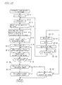
- FIG. 8 , FIG. 9 and FIG. 10 are flowcharts illustrating the normal control operation prior to the assist control.
- the controller 1 firstly performs the conduction check process of the first stage (Step S1) to subsequently perform the conduction check process of the second stage (Step S2) to subsequently starts the normal assist control (Step S3).
- the conduction check process of the first stage is performed based on the flowchart shown in FIG. 9 .
- the controller 1 (mainly the function of the relay checker 1f) sets the initial value of the count value N to 0 (Step S1-1).
- the controller 1 excites the relay 11 to close the contacts 11a (Step S1-2).
- the controller 1 detects the current position of the rotor 6r based on the output from the rotation angle sensor 10 (Step S1-3).
- Step S1-4 the controller 1 calculates an energization angle corresponding to the nearest zero point to the current position (electric angle) of the rotor 6r (a phase at which the current value is 0 is assumed as the first phase).
- the nearest zero point to the current position ⁇ 0 of the rotor 6r is an energization angle at which the phase U has the current value of 0.
- the energization angle ⁇ 1 is calculated so that currents that have an identical absolute value and that have different signs are energized for the other phases V and W (Step S1-4) to set the energization angle ⁇ 1 as a target electric angle (Step S1-5).
- Step S1-6 the controller 1 starts the internal timer (set time T1) (Step S1-6) to control the motor current (Step S1-7).
- This control is performed by allowing the relay checker 1f to instruct the two-phase/three-phase converter 1e to control the motor driving circuit 5 so that the current of 0[A] flows at the phase U, the current of -I[A] flows at the phase V, and the current of I[A] flows at the phase W, respectively.
- the currents actually flowing in the current paths L V and L W of the phases V and W are detected based on the output from the current detection circuit 13 (Step S1-8).
- the rotor 6r is rotated to the position at the electric angle ⁇ 1 ( FIG. 7A ).
- the above I[A] is on the order of a few amperes for example.
- the conduction check can be performed securely. Even when the surface of the contact 11a has thereon metal foreign matters or an oxide layer, the metal foreign matters or oxide layer can be fused or can be thermally destroyed and can be removed.
- This energization of current is continuously performed until the set time T1 is passed (Step S1-9).
- the controller 1 determines, with regard to the second phase (the phase V) and the third phase (the phase W) respectively, whether the absolute values of the currents exceed the threshold value or not (Steps S1-10 and S1-11).
- the controller 1 determines that each contact 11 a has a favorable conduction to subsequently perform the conduction check process of the second stage (Step S2 of FIG. 8 ).
- the above threshold value may be set to be lower than the absolute values of the currents I and -I in consideration of a factor that how much the absolute value of the current I flowing at the phases V and W is reduced when any one of the contacts 11a has an increased contact resistance and has an abnormal value.
- Step S1-12 When any one of the currents for the phase V and the phase W is equal to or lower than the threshold value on the other hand, whether N reaches a predetermined value or not is determined (Step S1-12).
- the value N means the number of execution of the conduction check process (and a foreign matter removal processing) by closing the contacts 11 a to pass high current.
- the value N is set to an integer of 2 or more.
- the time T2 is a waiting time for waiting when the relay 11 is not excited and the contacts 11a are securely opened.
- the controller 1 returns to Step S1-2 to excite the relay 11 again. Thereafter, the same processing is repeated until the value N reaches the predetermined value.
- Step S2 of FIG. 8 the controller 1 starts the assist control (Step S2 of FIG. 8 ).
- the controller 1 also performs the conduction check process of the second stage.
- the determination of "YES" in Step S1-12 also may be followed by a step of providing an alarm display showing that the contact 11a has a defective electrical conductivity.
- the conduction check process of the second stage is performed based on the flowchart shown in FIG. 10 .
- the controller 1 (mainly the function of the relay checker 1f) sets the initial value of the count value N to 0 (Step S2-1).
- the controller 1 excites the relay 11 (or continues the excitation when the relay 11 is already excited) to close the contacts 11a (Step S2-2).
- the controller 1 detects the current position of the rotor 6r based on the output from the rotation angle sensor 10 (Step S2-3).
- Step S2-4 the controller 1 calculates the energization angle at the nearest zero point to the current position of the rotor 6r at which any one of the second phase and the third phase has a current value of 0.
- an energization angle at the nearest zero point to the current position ⁇ 1 of the rotor 6r at which phases other than the phase U have a current value of 0 is an energization angle at which the phase V has a current value of 0 for example.
- the energization angle ⁇ 2 is calculated so that currents that have an identical absolute value and that have different signs are energized at the phase U and the phase W other than the phase V (Step S2-4) to set the energization angle ⁇ 2 as a target electric angle (Step S2-5).
- the wording "the energization angle ⁇ 2 is calculated" specifically means the following. Specifically, at the current position ⁇ 1 of the rotor 6r (electric angle) when the conduction check process of the first stage is performed, the phase U has a current value of 0. Thus, at the rotor position plus or minus 60° from the angle ⁇ 1 , the phase V or the phase W has a current value of 0. Thus, the rotor position at ( ⁇ 1 +60°) or ( ⁇ 1 -60°) can be assumed as a target electric angle.
- Step S2-6) the controller 1 starts the internal timer (set time T1) (Step S2-6) to control the motor current (Step S2-7).
- This control is performed by allowing the relay checker 1f to instruct the two-phase/three-phase converter 1e to control the motor driving circuit 5 so that the current of -I[A] flows at the phase U, the current of 0[A] flows at the phase V, and the current of I[A] flows at the phase W.
- the currents actually flowing in the current paths L U and L W at the phases U and W are detected by the output from the current detection circuit 13 (Step S2-8).
- the rotor 6r is rotated to the position at the electric angle ⁇ 2 ( FIG. 7B ). This rotation angle is 60°.
- the above I[A] is on the order of a few amperes for example.
- This energization of current is continuously performed until the set time T1 is passed (Step S2-9).
- the controller 1 determines, with regard to the first phase (the phase U), whether the absolute value of the current exceeds a threshold value or not (Step S2-10).
- the controller 1 assumes that the contact 11a has a favorable conduction to complete the processing to subsequently start the normal assist control (Step S3 of FIG. 8 ).
- the above threshold value can be set to be lower than the absolute value of the current -I in consideration of a factor that how much the absolute value of the current -I flowing at the phase U is reduced when any one of the contacts 11a has an increased contact resistance and has an abnormal value.
- Step S2-12 When the current of the phase U is equal to or lower than the threshold value on the other hand, whether the value N reaches the predetermined value or not is judged (Step S2-12).
- This value N means the number of execution of the conduction check process (and a foreign matter removal processing) by closing the contacts 11a to pass high current.
- the value N is set to an integer of 2 or more.
- the time T2 is a waiting time for waiting when the relay 11 is not excited and the contacts 11a are securely opened.
- the controller 1 returns to Step S2-2 to excite the relay 11 again. Thereafter, the same processing is repeated until the value N reaches the predetermined value.
- Step S3 of FIG. 8 When the repetition of the conduction check process results in the current of the phase U having an absolute value exceeding the threshold value, the controller 1 starts the assist control (Step S3 of FIG. 8 ). When the value N reaches the predetermined value while the current of the phase U still having an absolute value equal to or lower than the threshold value on the other hand, the controller 1 also starts the assist control.
- the determination of "YES" in Step S2-12 of FIG. 10 also may be followed by a step of providing an alarm display showing that the contact 11a has a defective electrical conductivity.
- no current flows in the current path of any one phase and currents that have an identical absolute value and that have different signs flow in the current paths of the other two phases.
- the status at one energization angle on the driving current waveform of the motor 6 can be given continuously and relatively-high current can simultaneously flow in the contacts 11a inserted to the two phases.
- no current also can flow in another phase to perform the same processing to flow current in a contact of the phase at which no current was firstly flowed.
- the electrical conductivities of all of the contacts inserted to the current paths of the three phases can be investigated.
- the conduction check can be performed securely.
- the flow of such high current also can fuse metal foreign matters or can thermally destroy an oxide layer.
- an improved function can be provided to remove foreign matters on the surface of the contact to recover a favorable electrical conductivity.
- the rotation angle of the rotor 6r can be suppressed to a smaller value because the conduction check process can be performed without being limited by a specific phase and while three phases being energized at an energization angle that is nearest to the current position of the rotor 6r and at which one phase has a current value of 0. Since the zero point exists at every 60° of an electric angle, the rotation angle of the rotor 6r also can be within the electric angle of 60°.
- the electric power steering apparatus 100 according to the third embodiment of the present invention has the same circuit configuration as that of the second embodiment.
- the electric power steering apparatus 100 according to the third embodiment has the circuit configuration as shown in the block diagram of FIG. 6 .
- three contacts should be subjected to the conduction check as in the second embodiment.
- the conduction check process must be performed based on two stages.
- an order of phases for which no current flows during the conduction check process is determined, For example, the order is the phase W, the phase V, and the phase U.
- the controller 1 sequentially memorizes this order and the phase for which no current flowed in the previous processing.
- the controller 1 memorizes this order and the phase for which no current flowed in the previous processing even when the ignition key 4 ( FIG. 6 ) is turned OFF.
- the next phase in this order will be "a phase for which no current flows"
- FIG. 11A and FIG. 11B illustrate driving current waveforms (i.e., field current waveforms) of three phases (U, V, and W) of the motor 6 in which the horizontal axis shows an electric angle (energization angle) and the vertical axis shows a current amplitude ratio.
- the nearest electric angle at the zero point at which the phase W has a current value of 0 is ⁇ 1 .
- the energization angle ⁇ 1 at which the phase W has a current value of 0 is set as a target electric angle in the first stage of the conduction check process.
- the energization angle at the nearest zero point at which the phase V has a current value of 0 is ⁇ 2 (i.e., ⁇ 1 -60°).
- the energization angle ⁇ 2 at which the phase V has a current value of 0 is set as a target electric angle in the second stage of the conduction check process.
- FIG. 8 , FIG. 12 , and FIG. 13 are flowcharts illustrating the normal control operation prior to the assist control.
- the control operation in FIG. 8 is as described in the second embodiment.
- the conduction check process of the first stage is performed based on the flowchart shown in FIG. 12 .
- the controller 1 (mainly the function of the relay checker 1f) sets the initial value of the count value N to 0 (Step S1-1).
- the controller 1 excites the relay 11 to close the contacts 11 a (Step S1-2).
- the controller 1 detects the current position of the rotor 6r (Step S1-3).
- Step S1-4 the controller 1 calculates the energization angle at the nearest zero point at which the predetermined first phase in the order (the phase W in this case) has a current value of 0, Specifically, in the example of FIG. 11A , the nearest zero point to the current position ⁇ 0 of the rotor 6r is at the energization angle ⁇ 1 .
- the controller 1 calculates the energization angle ⁇ 1 (Step S1-4) to set the energization angle ⁇ 1 as a target electric angle (Step S1-5).
- currents that have an identical absolute value and that have different signs can be energized at the phases U and V.
- Step S1-6 the controller 1 starts the internal timer (set time T1) (Step S1-6) to control the motor current (Step S1-7).
- This control is performed by allowing the relay checker 1f to instruct the two-phase/three-phase converter 1e to control the motor driving circuit 5 so that the current of -I[A] flows at the phase U, the current of I[A] flows at the phase V, and the current of 0[A] flows at the phase W, respectively.
- the currents actually flowing in the current paths L U and L V of the phases U and V are detected by the output from the current detection circuit 13 (Step S1-8).
- the rotor 6r is rotated to the position at the electric angle ⁇ 1 ( FIG. 11A ).
- the above current I[A] is on the order of a few amperes for example. By flowing of such high current, the conduction check can be performed securely. Even when the surface of the contact 11a has thereon metal foreign matters or an oxide layer, the metal foreign matters or oxide layer can be fused or can be thermally destroyed and can be removed. This energization of current is continuously performed until the set time T1 is passed (Step S1-9). When the set time T1 has passed since the start of the flow of the current, the controller 1 determines, with regard to the second phase (the phase U) and the third phase (the phase V) respectively, whether the absolute values of the currents exceed the threshold value or not (Steps S1-10 and S1-11).
- the controller 1 determines that each contact 11a has a favorable conduction to complete the processing to subsequently start the conduction check process of the second stage (Step S2 of FIG. 8 ).
- the above threshold value may be set to be lower than the absolute values of the currents I and -I in consideration of a factor that how much the absolute value of the current I flowing at the phases U and V is reduced when any one of the contacts 11a has an increased contact resistance and has an abnormal value.
- Step S1-12 When any one of the currents for the second phase (the phase U) and the third phase (the phase V) is equal to or lower than the threshold value on the other hand, whether N reaches a predetermined value or not is determined (Step S1-12).
- the value N means the number of execution of the conduction check process (and a foreign matter removal processing) by closing the contacts 11 a to pass high current.
- the value N is set to an integer of 2 or more.
- Step S1-12 the controller 1 once returns the relay 11 to a not-excited status (Step S1-13) and increases the value N by one (Step S1-14) to start the internal timer (set time T2) (Step S 1-15) to wait when the time T2 is passed (Step S1-16).
- the time T2 is a waiting time for waiting when the relay 11 is not excited and the contacts 11a are securely opened.
- the controller 1 returns to Step S1-2 to excite the relay 11 again. Thereafter, the same processing is repeated until the value N reaches the predetermined value.
- Step S2 of FIG. 8 When the repetition of the conduction check process results in the currents of the second phase (the phase U) and the third phase (the phase V) having an absolute value exceeding the threshold value, the controller 1 performs the conduction check process of the second stage (Step S2 of FIG. 8 ).
- the controller 1 also performs the conduction check process of the second stage.
- the determination of "YES" in Step S1-12 also may be followed by a step of providing an alarm display showing that the contact 11a has a defective electrical conductivity.
- the conduction check process of the second stage is performed based on the flowchart shown in FIG. 13 .
- the controller 1 (mainly the function of the relay checker 1f) sets the initial value of the count value N to 0 (Step S2-1).
- the controller 1 excites the relay 11 (or continues the excitation when the relay 11 is already excited) to close the contacts 11a (Step S2-2).
- the controller 1 detects the current position of the rotor 6r (Step S2-3).
- Step S2-4 the controller 1 calculates the nearest energization angle at which the phase V has a current value of 0 and which is at the next phase in the order when seen from the current position of the rotor 6r.
- the nearest energization angle to the current position of the rotor 6r ⁇ 1 at which the phase V has a current value of 0 is found to calculate the energization angle ⁇ 2 (Step S2-4) to set the energization angle ⁇ 2 as a target electric angle (Step S2-5).
- currents that have an identical absolute value and that have different signs can be energized at the phases U and W.
- Step S2-6 the controller 1 starts the internal timer (set time T1) (Step S2-6) to control the motor current (Step S2-7),
- This control is performed by allowing the relay checker 1f to instruct the two-phase/three-phase converter 1e to control the motor driving circuit 5 so that the current of -I[A] flows at the phase U, the current of 0[A] flows at the phase V, and the current of I[A] flows at the phase W, respectively.
- the currents actually flowing in the current paths L U and L W of the phases U and W are detected based on the output from the current detection circuit 13 (Step S2-8).
- the rotor 6r is rotated to the position at the electric angle ⁇ 2 ( FIG. 11B ). This rotation angle is 60°.
- the above I[A] is on the order of a few amperes for example.
- the flow of such high current can provide a secure conduction check. Even metal foreign matters or an oxide layer on the surface of the contact 11a can be fused or thermally destroyed and can be removed.
- This current energization is continuously performed until the set time T1 is passed (Step S2-9).
- the controller 1 determines, with regard to the first phase (the phase W), whether the absolute value of the current exceeds the threshold value or not (Step S2-10).
- the controller 1 When the absolute value of the current exceeds the threshold value, the controller 1 assumes that the contact 11a has a favorable conduction to complete the processing to subsequently start the normal assist control (Step S3 of FIG. 8 ).
- the above threshold value can be set to be lower than the absolute value of the current I in consideration of a factor that how much the absolute value of the current I flowing at the first phase (the phase W) is reduced when any one of the contacts 11a has an increased contact resistance and has an abnormal value.
- Step S2-12 When the current of the first phase (the phase W) is equal to or lower than the threshold value on the other hand, whether the value N reaches the predetermined value or not is judged (Step S2-12).
- the value N means the number of execution of the conduction check process (and a foreign matter removal processing) by closing the contacts I 1a to pass high current.
- the value N is set to an integer of 2 or more.
- the time T2 is a waiting time for waiting when the relay 11 is not excited and the contacts 11a are securely opened.
- the controller 1 returns to Step S2-2 to excite the relay 11 again. Thereafter, the same processing is repeated until the value N reaches the predetermined value.
- Step S3 of FIG. 8 When the repetition of the conduction check process results in the current of the first phase (the phase W) having an absolute value exceeding the threshold value, the controller 1 starts the assist control (Step S3 of FIG. 8 ). When the value N reaches the predetermined value while the current of the first phase (the phase W) still having an absolute value equal to or lower than the threshold value on the other hand, the controller 1 also starts the assist control.
- the determination of "YES" in Step S2-12 of FIG. 13 also may be followed by a step of providing an alarm display showing that the contact 11a has a defective electrical conductivity.
- the absolute values of the currents of the respective phases U, V, and W exceed the threshold value after one energization.
- the total of two energizations are performed for the phase U in the first and second stages, one energization is performed for the phase V in the first stage, and one energization is performed for the phase W in the second stage.
- no current flows in the current path of one phase and currents that have an identical absolute value and that have different signs flow in the current paths of the other two phases.
- the status at one energization angle on the driving current waveform of the motor 6 can be given continuously and relatively-high currents can simultaneously flow in the contacts 11a inserted to the two phases.
- no current also can flow in another phase to perform the same processing to pass current in a contact of the phase at which no current firstly flowed.
- the conduction check can be performed securely.
- the flow of such high current also can fuse metal foreign matters or can thermally destroy an oxide layer.
- an improved function can be provided to remove foreign matters on the surface of the contact to recover a favorable electrical conductivity.
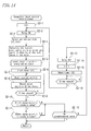
- FIG. 14 is a flowchart illustrating another conduction check process in the second stage.
- FIG. 14 is different from FIG. 13 in that Step S2-11 is provided to carry out the comparison with the threshold value in the second stage also with regard to the phase for which the comparison with the threshold value was carried out in the first stage.
- the second and third embodiments also can select the reduction ratio so that (motor pole number) ⁇ (reduction ratio) is 90° or more to limit, even when the rotor 6r is rotated at the electric angle of 90° at maximum, the rotation of the steering wheel 9 to 2° or less.
- the rotation of the steering wheel 9 limited to 2° or less can prevent the driver from noticing the rotation. Specifically, even when the steering wheel 9 is slightly rotated due to the conduction check process for the contacts 11a, the driver can be prevented from noticing the rotation to feel uncomfortable.
- the respective embodiments have shown one relay 11 including a plurality of contacts 11a, two or three relays including respective contacts may be inserted so that the controller 1 can individually control the respective relays (the respective contacts).
Landscapes
- Engineering & Computer Science (AREA)
- Chemical & Material Sciences (AREA)
- Combustion & Propulsion (AREA)
- Transportation (AREA)
- Mechanical Engineering (AREA)
- Power Steering Mechanism (AREA)
- Control Of Motors That Do Not Use Commutators (AREA)
- Steering Control In Accordance With Driving Conditions (AREA)
Applications Claiming Priority (1)
| Application Number | Priority Date | Filing Date | Title |
|---|---|---|---|
| JP2007274600A JP5243767B2 (ja) | 2007-10-23 | 2007-10-23 | 電動パワーステアリング装置 |
Publications (3)
| Publication Number | Publication Date |
|---|---|
| EP2052948A2 true EP2052948A2 (de) | 2009-04-29 |
| EP2052948A3 EP2052948A3 (de) | 2010-03-03 |
| EP2052948B1 EP2052948B1 (de) | 2011-12-14 |
Family
ID=40278899
Family Applications (1)
| Application Number | Title | Priority Date | Filing Date |
|---|---|---|---|
| EP08167161A Ceased EP2052948B1 (de) | 2007-10-23 | 2008-10-21 | Elektrische Servolenkung |
Country Status (3)
| Country | Link |
|---|---|
| US (1) | US8538632B2 (de) |
| EP (1) | EP2052948B1 (de) |
| JP (1) | JP5243767B2 (de) |
Cited By (1)
| Publication number | Priority date | Publication date | Assignee | Title |
|---|---|---|---|---|
| US8798844B2 (en) | 2010-08-04 | 2014-08-05 | Trw Limited | Diagnostic method and apparatus for electric power steering system |
Families Citing this family (10)
| Publication number | Priority date | Publication date | Assignee | Title |
|---|---|---|---|---|
| JP5251469B2 (ja) * | 2008-12-08 | 2013-07-31 | 日本精工株式会社 | 電動パワーステアリング装置 |
| JP5616281B2 (ja) * | 2011-04-15 | 2014-10-29 | 日立オートモティブシステムズステアリング株式会社 | トルクセンサおよびパワーステアリング装置 |
| WO2014073339A1 (ja) * | 2012-11-09 | 2014-05-15 | 日産自動車株式会社 | 車両制御装置 |
| JP6108043B2 (ja) * | 2014-09-04 | 2017-04-05 | 日本精工株式会社 | モータ制御装置、故障検出方法並びにそれらを搭載した電動パワーステアリング装置及び車両 |
| DE102015206880A1 (de) * | 2015-04-16 | 2016-10-20 | Geze Gmbh | Antriebssteuerung für einen Drehstromantrieb |
| US10581274B2 (en) | 2015-06-03 | 2020-03-03 | Lg Electronics Inc. | Home appliance |
| KR101698775B1 (ko) * | 2015-08-11 | 2017-01-23 | 엘지전자 주식회사 | 홈 어플라이언스 |
| KR101663520B1 (ko) * | 2015-08-11 | 2016-10-07 | 엘지전자 주식회사 | 모터 구동장치 및 이를 구비하는 홈 어플라이언스 |
| JP7232068B2 (ja) * | 2019-02-07 | 2023-03-02 | 株式会社Subaru | 電力供給システム |
| JP7499350B2 (ja) * | 2020-04-20 | 2024-06-13 | ティッセンクルップ・プレスタ・アクチエンゲゼルシヤフト | ステアバイワイヤーステアリングシステムの劣化コンセプト |
Citations (3)
| Publication number | Priority date | Publication date | Assignee | Title |
|---|---|---|---|---|
| JPS63237319A (ja) | 1987-03-26 | 1988-10-03 | 株式会社 三ツ葉電機製作所 | モ−タ制御用スイツチ接点の信頼性確保装置 |
| JP2006182166A (ja) | 2004-12-27 | 2006-07-13 | Favess Co Ltd | 電動パワーステアリング装置 |
| JP2006211825A (ja) | 2005-01-28 | 2006-08-10 | Nsk Ltd | 電動パワーステアリング装置 |
Family Cites Families (14)
| Publication number | Priority date | Publication date | Assignee | Title |
|---|---|---|---|---|
| JPH0733312Y2 (ja) * | 1988-04-08 | 1995-07-31 | 本田技研工業株式会社 | 制御回路用スイッチ接点の自己清浄装置 |
| JPH0740849A (ja) * | 1993-07-26 | 1995-02-10 | Aisin Seiki Co Ltd | 車両の操舵制御装置 |
| JP4273554B2 (ja) * | 1999-02-05 | 2009-06-03 | アイシン・エィ・ダブリュ株式会社 | モータ駆動装置の異常検出装置及び異常検出方法 |
| JP2001008483A (ja) * | 1999-06-16 | 2001-01-12 | Yamaha Motor Co Ltd | 電動車両の駆動制御装置 |
| US6392854B1 (en) * | 2000-07-27 | 2002-05-21 | Motorola, Inc. | Method and system for testing continuity of a motor and associated drive circuitry |
| JP3982739B2 (ja) * | 2001-05-08 | 2007-09-26 | 本田技研工業株式会社 | 電動パワーステアリング装置 |
| US6519518B1 (en) * | 2001-08-01 | 2003-02-11 | Delphi Technologies, Inc. | Method for detecting motor control loss in a power steering system |
| JP3839358B2 (ja) * | 2002-06-12 | 2006-11-01 | 株式会社ジェイテクト | 車両の操舵制御装置及び車両の操舵制御方法 |
| JP4248960B2 (ja) * | 2003-07-23 | 2009-04-02 | 株式会社デンソー | 伝達比可変操舵装置 |
| JP4267976B2 (ja) * | 2003-07-29 | 2009-05-27 | 本田技研工業株式会社 | 電動パワーステアリング装置 |
| JP2005253156A (ja) * | 2004-03-02 | 2005-09-15 | Denso Corp | 車両用モータ制御装置の故障検出装置 |
| FR2876972B1 (fr) * | 2004-10-25 | 2006-12-29 | Koyo Steering Europ K S E Soc | Procede pour la determination de la position angulaire du volant de conduite d'une direction assistee electrique de vehicule automobile |
| JP4644013B2 (ja) * | 2005-03-25 | 2011-03-02 | 本田技研工業株式会社 | 電動パワーステアリング装置 |
| JP2007223436A (ja) * | 2006-02-22 | 2007-09-06 | Nsk Ltd | リレー回路及びこれを用いた電動パワーステアリング制御装置 |
-
2007
- 2007-10-23 JP JP2007274600A patent/JP5243767B2/ja not_active Expired - Fee Related
-
2008
- 2008-10-21 EP EP08167161A patent/EP2052948B1/de not_active Ceased
- 2008-10-21 US US12/289,102 patent/US8538632B2/en not_active Expired - Fee Related
Patent Citations (3)
| Publication number | Priority date | Publication date | Assignee | Title |
|---|---|---|---|---|
| JPS63237319A (ja) | 1987-03-26 | 1988-10-03 | 株式会社 三ツ葉電機製作所 | モ−タ制御用スイツチ接点の信頼性確保装置 |
| JP2006182166A (ja) | 2004-12-27 | 2006-07-13 | Favess Co Ltd | 電動パワーステアリング装置 |
| JP2006211825A (ja) | 2005-01-28 | 2006-08-10 | Nsk Ltd | 電動パワーステアリング装置 |
Cited By (1)
| Publication number | Priority date | Publication date | Assignee | Title |
|---|---|---|---|---|
| US8798844B2 (en) | 2010-08-04 | 2014-08-05 | Trw Limited | Diagnostic method and apparatus for electric power steering system |
Also Published As
| Publication number | Publication date |
|---|---|
| JP5243767B2 (ja) | 2013-07-24 |
| JP2009101807A (ja) | 2009-05-14 |
| EP2052948A3 (de) | 2010-03-03 |
| US20090150027A1 (en) | 2009-06-11 |
| EP2052948B1 (de) | 2011-12-14 |
| US8538632B2 (en) | 2013-09-17 |
Similar Documents
| Publication | Publication Date | Title |
|---|---|---|
| EP2052948B1 (de) | Elektrische Servolenkung | |
| EP2037566B1 (de) | Mehrphasige Wechselstrom-Motorantriebsvorrichtung | |
| KR100863390B1 (ko) | 모터 구동 회로의 지락 검출 장치 | |
| JP4333751B2 (ja) | ブラシレスモータの駆動装置 | |
| JP4572168B2 (ja) | リレー接点の溶着の検出方法及び装置 | |
| US8315028B2 (en) | Overcurrent protection apparatus | |
| CN103812403B (zh) | 马达控制装置、马达控制方法及电动助力转向装置 | |
| CN101883707B (zh) | 电动动力转向装置 | |
| KR100673740B1 (ko) | 모터 제어 장치 | |
| CN102341263B (zh) | 用于在多相电机运行期间对其电流传感器诊断的方法 | |
| JPH0974794A (ja) | 交流電動機制御回路の異常検出装置 | |
| JP5441481B2 (ja) | インバータ装置の故障診断方法 | |
| JP2019110720A (ja) | 異常検出装置 | |
| JP2006320176A (ja) | インバータの診断方法及び装置 | |
| JP2007060762A (ja) | 負荷駆動システムの故障検出装置 | |
| JP5223367B2 (ja) | 駆動装置 | |
| JP4671334B2 (ja) | 駆動装置の故障検出回路 | |
| EP2073370B1 (de) | Motorsteuereinrichtung | |
| JP2010132206A (ja) | 電動パワーステアリング装置 | |
| JP2013256143A (ja) | 電動パワーステアリング制御装置 | |
| JP2000125586A (ja) | 故障診断方法および装置 | |
| CN111641364A (zh) | 电机驱动控制装置 | |
| JP4382768B2 (ja) | 電動パワーステアリング装置 | |
| CN120077284A (zh) | 用于检测流过二极管的电流的装置和方法、电驱动系统 | |
| EP2037565B1 (de) | Mehrphasige Wechselstrom-Motorantriebsvorrichtung |
Legal Events
| Date | Code | Title | Description |
|---|---|---|---|
| PUAI | Public reference made under article 153(3) epc to a published international application that has entered the european phase |
Free format text: ORIGINAL CODE: 0009012 |
|
| AK | Designated contracting states |
Kind code of ref document: A2 Designated state(s): AT BE BG CH CY CZ DE DK EE ES FI FR GB GR HR HU IE IS IT LI LT LU LV MC MT NL NO PL PT RO SE SI SK TR |
|
| AX | Request for extension of the european patent |
Extension state: AL BA MK RS |
|
| PUAL | Search report despatched |
Free format text: ORIGINAL CODE: 0009013 |
|
| AK | Designated contracting states |
Kind code of ref document: A3 Designated state(s): AT BE BG CH CY CZ DE DK EE ES FI FR GB GR HR HU IE IS IT LI LT LU LV MC MT NL NO PL PT RO SE SI SK TR |
|
| AX | Request for extension of the european patent |
Extension state: AL BA MK RS |
|
| RIC1 | Information provided on ipc code assigned before grant |
Ipc: G01R 31/02 20060101ALI20100128BHEP Ipc: B62D 5/04 20060101AFI20090130BHEP |
|
| 17P | Request for examination filed |
Effective date: 20100901 |
|
| AKX | Designation fees paid |
Designated state(s): DE FR |
|
| GRAP | Despatch of communication of intention to grant a patent |
Free format text: ORIGINAL CODE: EPIDOSNIGR1 |
|
| RIC1 | Information provided on ipc code assigned before grant |
Ipc: G01R 31/02 20060101ALI20110520BHEP Ipc: B62D 5/04 20060101AFI20110520BHEP |
|
| GRAS | Grant fee paid |
Free format text: ORIGINAL CODE: EPIDOSNIGR3 |
|
| GRAA | (expected) grant |
Free format text: ORIGINAL CODE: 0009210 |
|
| AK | Designated contracting states |
Kind code of ref document: B1 Designated state(s): DE FR |
|
| REG | Reference to a national code |
Ref country code: DE Ref legal event code: R096 Ref document number: 602008011947 Country of ref document: DE Effective date: 20120308 |
|
| PLBE | No opposition filed within time limit |
Free format text: ORIGINAL CODE: 0009261 |
|
| STAA | Information on the status of an ep patent application or granted ep patent |
Free format text: STATUS: NO OPPOSITION FILED WITHIN TIME LIMIT |
|
| 26N | No opposition filed |
Effective date: 20120917 |
|
| REG | Reference to a national code |
Ref country code: DE Ref legal event code: R097 Ref document number: 602008011947 Country of ref document: DE Effective date: 20120917 |
|
| REG | Reference to a national code |
Ref country code: FR Ref legal event code: PLFP Year of fee payment: 9 |
|
| REG | Reference to a national code |
Ref country code: FR Ref legal event code: PLFP Year of fee payment: 10 |
|
| REG | Reference to a national code |
Ref country code: FR Ref legal event code: PLFP Year of fee payment: 11 |
|
| PGFP | Annual fee paid to national office [announced via postgrant information from national office to epo] |
Ref country code: FR Payment date: 20200914 Year of fee payment: 13 |
|
| PGFP | Annual fee paid to national office [announced via postgrant information from national office to epo] |
Ref country code: DE Payment date: 20201006 Year of fee payment: 13 |
|
| REG | Reference to a national code |
Ref country code: DE Ref legal event code: R119 Ref document number: 602008011947 Country of ref document: DE |
|
| PG25 | Lapsed in a contracting state [announced via postgrant information from national office to epo] |
Ref country code: DE Free format text: LAPSE BECAUSE OF NON-PAYMENT OF DUE FEES Effective date: 20220503 |
|
| PG25 | Lapsed in a contracting state [announced via postgrant information from national office to epo] |
Ref country code: FR Free format text: LAPSE BECAUSE OF NON-PAYMENT OF DUE FEES Effective date: 20211031 |