EP2050833B1 - Tube en acier soudé de haute tension pour élément structural automobile et son procédé de fabrication - Google Patents
Tube en acier soudé de haute tension pour élément structural automobile et son procédé de fabrication Download PDFInfo
- Publication number
- EP2050833B1 EP2050833B1 EP07767459.6A EP07767459A EP2050833B1 EP 2050833 B1 EP2050833 B1 EP 2050833B1 EP 07767459 A EP07767459 A EP 07767459A EP 2050833 B1 EP2050833 B1 EP 2050833B1
- Authority
- EP
- European Patent Office
- Prior art keywords
- steel tube
- tube
- steel
- stress
- less
- Prior art date
- Legal status (The legal status is an assumption and is not a legal conclusion. Google has not performed a legal analysis and makes no representation as to the accuracy of the status listed.)
- Active
Links
Images

Classifications
-
- C—CHEMISTRY; METALLURGY
- C22—METALLURGY; FERROUS OR NON-FERROUS ALLOYS; TREATMENT OF ALLOYS OR NON-FERROUS METALS
- C22C—ALLOYS
- C22C38/00—Ferrous alloys, e.g. steel alloys
- C22C38/14—Ferrous alloys, e.g. steel alloys containing titanium or zirconium
-
- B—PERFORMING OPERATIONS; TRANSPORTING
- B21—MECHANICAL METAL-WORKING WITHOUT ESSENTIALLY REMOVING MATERIAL; PUNCHING METAL
- B21C—MANUFACTURE OF METAL SHEETS, WIRE, RODS, TUBES OR PROFILES, OTHERWISE THAN BY ROLLING; AUXILIARY OPERATIONS USED IN CONNECTION WITH METAL-WORKING WITHOUT ESSENTIALLY REMOVING MATERIAL
- B21C37/00—Manufacture of metal sheets, bars, wire, tubes or like semi-manufactured products, not otherwise provided for; Manufacture of tubes of special shape
- B21C37/06—Manufacture of metal sheets, bars, wire, tubes or like semi-manufactured products, not otherwise provided for; Manufacture of tubes of special shape of tubes or metal hoses; Combined procedures for making tubes, e.g. for making multi-wall tubes
- B21C37/08—Making tubes with welded or soldered seams
-
- C—CHEMISTRY; METALLURGY
- C21—METALLURGY OF IRON
- C21D—MODIFYING THE PHYSICAL STRUCTURE OF FERROUS METALS; GENERAL DEVICES FOR HEAT TREATMENT OF FERROUS OR NON-FERROUS METALS OR ALLOYS; MAKING METAL MALLEABLE, e.g. BY DECARBURISATION OR TEMPERING
- C21D1/00—General methods or devices for heat treatment, e.g. annealing, hardening, quenching or tempering
- C21D1/26—Methods of annealing
-
- C—CHEMISTRY; METALLURGY
- C21—METALLURGY OF IRON
- C21D—MODIFYING THE PHYSICAL STRUCTURE OF FERROUS METALS; GENERAL DEVICES FOR HEAT TREATMENT OF FERROUS OR NON-FERROUS METALS OR ALLOYS; MAKING METAL MALLEABLE, e.g. BY DECARBURISATION OR TEMPERING
- C21D8/00—Modifying the physical properties by deformation combined with, or followed by, heat treatment
- C21D8/02—Modifying the physical properties by deformation combined with, or followed by, heat treatment during manufacturing of plates or strips
- C21D8/0221—Modifying the physical properties by deformation combined with, or followed by, heat treatment during manufacturing of plates or strips characterised by the working steps
- C21D8/0226—Hot rolling
-
- C—CHEMISTRY; METALLURGY
- C21—METALLURGY OF IRON
- C21D—MODIFYING THE PHYSICAL STRUCTURE OF FERROUS METALS; GENERAL DEVICES FOR HEAT TREATMENT OF FERROUS OR NON-FERROUS METALS OR ALLOYS; MAKING METAL MALLEABLE, e.g. BY DECARBURISATION OR TEMPERING
- C21D8/00—Modifying the physical properties by deformation combined with, or followed by, heat treatment
- C21D8/02—Modifying the physical properties by deformation combined with, or followed by, heat treatment during manufacturing of plates or strips
- C21D8/0247—Modifying the physical properties by deformation combined with, or followed by, heat treatment during manufacturing of plates or strips characterised by the heat treatment
- C21D8/0263—Modifying the physical properties by deformation combined with, or followed by, heat treatment during manufacturing of plates or strips characterised by the heat treatment following hot rolling
-
- C—CHEMISTRY; METALLURGY
- C21—METALLURGY OF IRON
- C21D—MODIFYING THE PHYSICAL STRUCTURE OF FERROUS METALS; GENERAL DEVICES FOR HEAT TREATMENT OF FERROUS OR NON-FERROUS METALS OR ALLOYS; MAKING METAL MALLEABLE, e.g. BY DECARBURISATION OR TEMPERING
- C21D9/00—Heat treatment, e.g. annealing, hardening, quenching or tempering, adapted for particular articles; Furnaces therefor
- C21D9/08—Heat treatment, e.g. annealing, hardening, quenching or tempering, adapted for particular articles; Furnaces therefor for tubular bodies or pipes
-
- C—CHEMISTRY; METALLURGY
- C22—METALLURGY; FERROUS OR NON-FERROUS ALLOYS; TREATMENT OF ALLOYS OR NON-FERROUS METALS
- C22C—ALLOYS
- C22C38/00—Ferrous alloys, e.g. steel alloys
- C22C38/02—Ferrous alloys, e.g. steel alloys containing silicon
-
- C—CHEMISTRY; METALLURGY
- C22—METALLURGY; FERROUS OR NON-FERROUS ALLOYS; TREATMENT OF ALLOYS OR NON-FERROUS METALS
- C22C—ALLOYS
- C22C38/00—Ferrous alloys, e.g. steel alloys
- C22C38/04—Ferrous alloys, e.g. steel alloys containing manganese
-
- C—CHEMISTRY; METALLURGY
- C22—METALLURGY; FERROUS OR NON-FERROUS ALLOYS; TREATMENT OF ALLOYS OR NON-FERROUS METALS
- C22C—ALLOYS
- C22C38/00—Ferrous alloys, e.g. steel alloys
- C22C38/12—Ferrous alloys, e.g. steel alloys containing tungsten, tantalum, molybdenum, vanadium, or niobium
-
- C—CHEMISTRY; METALLURGY
- C21—METALLURGY OF IRON
- C21D—MODIFYING THE PHYSICAL STRUCTURE OF FERROUS METALS; GENERAL DEVICES FOR HEAT TREATMENT OF FERROUS OR NON-FERROUS METALS OR ALLOYS; MAKING METAL MALLEABLE, e.g. BY DECARBURISATION OR TEMPERING
- C21D2211/00—Microstructure comprising significant phases
- C21D2211/005—Ferrite
Definitions
- the present invention relates to high-tensile strength welded steel tubes, having a yield strength of greater than 660 MPa, suitable for automobile structural parts such as torsion beams, axle beams, trailing arms, and suspension arms.
- the present invention relates to a high-tensile strength welded steel tube which is used for torsion beams and which has excellent formability and high torsional fatigue endurance after the tube is formed into cross-sectional shape and is then stress-relief annealed and also relates to a method of producing the high-tensile strength welded steel tube.
- Patent Document 1 discloses a method of producing an ultra-high tensile strength electrically welded steel tube for structural parts of automobiles and the like.
- a steel material in which the content of C, Si, Mn, P, S, Al, and/or N is appropriately adjusted and which contains 0.0003% to 0.003% B and one or more of Mo, Ti Nb, and V is finish-rolled at a temperature ranging from its Ar3 transformation point to 950°C and is then hot-rolled into a steel strip for tubes in such a manner that the steel material is coiled at 250°C or lower, the steel strip is formed into an electrically welded steel tube, and the electrically welded steel tube is aged at a temperature of 500°C to 650°C.
- an ultra-high tensile strength steel tube having a tensile strength of greater than 1000 MPa can be obtained without performing thermal refining because of transformation strengthening due to B and precipitation hardening due to Mo, Ti, and/or Nb.
- Patent Document 2 discloses a method of producing an electrically welded steel tube suitable for door impact beams and stabilizers of automobiles and which has a high tensile strength of 1470 N/mm 2 or more and high ductility.
- the electrically welded steel tube is produced from a steel sheet made of a steel material which contains 0.18% to 0.28% C, 0.10% to 0.50% Si, 0.60% to 1.80% Mn, 0.020% to 0.050% Ti, 0.0005% to 0.0050% B, and one or more of Cr, Mo, and Nb and in which the amount of P and S is appropriately adjusted; is normalized at a temperature of 850°C to 950°C, and is then quenched.
- an electrically welded steel tube having a high strength of 1470 N/mm 2 or more and a ductility of about 10% to 18% can be obtained.
- This electrically welded steel tube is suitable for door impact beams and stabilizers of automobiles.
- JP 2003 321748 A The purpose of JP 2003 321748 A is to provide a high tensile strength welded steel tube which has a strength satisfying a tensile strength of ⁇ 590 MPa and which combines excellent workability and excellent fatigue properties, and to provide a production method thereof.
- JP 2003 321748 A discloses a high tensile strength welded steel tube having a composition containing, by weight, 0.035 to 0.185% C, 0.75 to 1.95% Mn, 0.01 to 0.49% Mo, 0.010 to 0.145% Ti, 0.011 to 0.10% Al, ⁇ 0.03% P, ⁇ 0.004% S, ⁇ 0.006% N and ⁇ 0.004% O, and the balance being substantially Fe.
- An electrically welded steel tube produced by the method disclosed in Patent Document 1 has a small elongation El of 14% or less and low ductility and therefore is low in formability; hence, there is a problem in that the tube is unsuitable for automobile structural parts, such as torsion beams and axle beams, made by press forming or hydro-forming.
- An electrically welded steel tube produced by the method disclosed in Patent Document 2 has an elongation El of up to 18% and is suitable for stabilizers formed by bending.
- this tube has ductility insufficient to produce structural parts by press forming or hydro-forming. Therefore, there is a problem in that this tube is unsuitable for automobile structural parts, such as torsion beams and axle beams, made by press forming or hydro-forming.
- the method disclosed in Patent Document 2 requires normalizing and quenching, is complicated, and is problematic in dimensional accuracy and economic efficiency.
- the present invention has been made to advantageously solve the problems of the conventional methods. It is an object of the present invention to provide a high-tensile strength welded steel tube which is suitable for automobile structural parts such as torsion beams and which is required to have excellent torsional fatigue endurance after the tube is formed into cross-sectional shape and is then stress-relief annealed. It is an object of the present invention to provide a method of producing an electrically welded steel tube for structural parts of automobiles without performing thermal refining. This tube has a yield strength of greater than 660 MPa, excellent low-temperature toughness, excellent formability, and excellent torsional fatigue endurance after this tube is formed into cross-sectional shape and is then stress-relief annealed.
- high-tensile strength welded steel tube means a welded steel tube with a yield strength YS of greater than 660 MPa.
- excellent formability means that a JIS #12 test specimen according to JIS Z 2201 has an elongation El of 15% or more (22% or more for a JIS #11 test specimen) as determined by a tensile test according to JIS Z 2241.
- excellent torsional fatigue endurance after forming into cross-sectional shape and then stress-relief annealing means that a steel tube has a ⁇ B /Ts ratio of 0.40 or more, wherein ⁇ B represents the 5 x 10 5 -cycle fatigue limit of the steel tube and TS represents the tensile strength of the steel tube.
- the 5 ⁇ 10 5 -cycle fatigue limit of the steel tube is determined in such a manner that a longitudinally central portion of the steel tube is formed so as to have a V-shape in cross section as shown in Fig. 3 (Fig. 11 of Japanese Unexamined Patent Application Publication No.
- the resulting steel tube is stress-relief annealed at 530°C for ten minutes, both end portions of the steel tube are fixed by chucking, and the steel tube is then subjected to a torsional fatigue test under completely reversed torsion at 1 Hz for 5 ⁇ 10 5 cycles.
- the "excellent torsional fatigue endurance after forming into cross-sectional shape and then stress-relief annealing" can be achieved in such a manner that forming into cross-sectional shape is performed as described above and stress-relief annealing is performed at 530°C for ten minutes such that a rate of change in cross-sectional hardness of -15% or more and a rate of reduction in residual stress of 50% or more are satisfied.
- excellent low-temperature toughness means that the following specimens both exhibit a fracture appearance transition temperature vTrs of -40°C or lower in a Charpy impact test: a V-notched test specimen (1/4-sized) prepared in such a manner that a longitudinally central portion of a test material (steel tube) is formed so as to have a V-shape in cross section as shown in Fig. 3 (Fig. 11 of Japanese Unexamined Patent Application Publication No.
- a flat portion of the test material is expanded such that the circumferential direction (C-direction) of a tube corresponds to the length direction of the test specimen, and the flat portion thereof is then cut out therefrom in accordance with JIS Z 2242 and a V-notched test specimen (1/4-sized) prepared in such a manner that a longitudinally central portion of a test material (steel tube) is formed so as to have a V-shape in cross section as shown in Fig. 3 (Fig. 11 of Japanese Unexamined Patent Application Publication No.
- the resulting test specimen is stress-relief annealed at 530°C for ten minutes, a flat portion of the test material is expanded such that the circumferential direction of a tube corresponds to the length direction of the test specimen, and the flat portion thereof is then cut out therefrom in accordance with JIS Z 2242.
- the inventors have conducted intensive systematic research on factors affecting ambivalent properties such as strength, low-temperature toughness, formability, torsional fatigue endurance after forming into cross-sectional shape and then stress-relief annealing and particularly on chemical components and production conditions of steel tubes.
- a high-tensile strength welded steel tube that has a yield strength of greater than 660 MPa, excellent low-temperature toughness, excellent formability, and excellent torsional fatigue endurance after being formed into cross-sectional shape and then stress-relief annealed can be produced in such a manner that a steel material (slab) in which the content of C, Si, Mn, and/or Al is adjusted within an appropriate range and which contains Ti and Nb is hot-rolled, under appropriate conditions, into a steel tube material (hot-rolled steel strip) in which a ferrite phase having an average grain size of 2 ⁇ m to 8 ⁇ m in circumferential cross section occupies 60 volume percent thereof and which has a microstructure in which a (Nb, Ti) composite carbide having an average grain size of 2 nm to 40 nm is precipitated in the ferrite phase, and the steel tube material is subjected to an electrically welded tube-making step under appropriate conditions such that a welded steel tube (slab) in which the content of C,
- the following tube can be produced at low cost without performing thermal refining: a high-tensile strength welded steel tube having a yield strength of greater than 660 MPa, excellent low-temperature toughness, excellent formability, and excellent torsional fatigue endurance after being stress-relief annealed.
- a high-tensile strength welded steel tube having a yield strength of greater than 660 MPa, excellent low-temperature toughness, excellent formability, and excellent torsional fatigue endurance after being stress-relief annealed.
- This is industrially particularly advantageous.
- the present invention is advantageous in remarkably enhancing properties of automobile structural parts.
- C is an element that increases the strength of steel and therefore is essential to secure the strength of the steel tube.
- C is diffused during stress-relief annealing, interacts with dislocations formed in an electrically welded tube-making step or during forming into cross-sectional shape to prevent the motion of the dislocations, prevents the initiation of fatigue cracks, and enhances torsional fatigue endurance. These effects are remarkable when the content of C is 0.03% or more.
- the C content is greater than 0.24%, the steel tube cannot have a ferrite-based microstructure in which a ferrite phase has a fraction of 60 volume percent or more, cannot secure a desired elongation, and has low formability and reduced low-temperature toughness. Therefore, the C content is limited to a range from 0.03% to 0.24% and is preferably 0.05% to 0.14%.
- Si is an element that accelerates ferritic transformation in a hot-rolling step.
- the content of Si needs to be 0.002% or more.
- the Si content is greater than 0.95%, the following properties are low: a rate of reduction in residual stress during stress-relief annealing subsequent to forming into cross-sectional shape, torsional fatigue endurance, surface properties, and electric weldability. Therefore, the Si content is limited to a range from 0.002% to 0.95% and is preferably 0.21% to 0.50%.
- Mn is an element that is involved in increasing the strength of steel, affects the interaction between C and the dislocations to prevent the motion of the dislocations, prevents the reduction of strength during stress-relief annealing subsequent to forming into cross-sectional shape, and prevents the initiation of fatigue cracks to enhance torsional fatigue endurance.
- the content of Mn needs to be 1.01% or more. Meanwhile, when the Mn content is greater than 1.99%, a desired microstructure or excellent formability cannot be achieved because ferritic transformation is inhibited. Therefore, the Mn content is limited to a range from 1.01% to 1.99% and is preferably 1.40% to 1.85%.
- Al is an element that acts as a deoxidizer during steel making, combines with nitrogen to prevent the growth of austenite grains in a hot-rolling step, and has a function of forming fine crystal grains.
- the content of Al needs to be 0.01% or more.
- the Al content is less than 0.01%, the ferrite phase is course.
- the Al content is greater than 0.08%, its effect is saturated and fatigue endurance is reduced because oxide inclusions are increased. Therefore, the Al content is limited to a range from 0.01% to 0.08% and is preferably 0.02% to 0.06%.
- Ti is an element that combines with N in steel to form TiN, reduces the amount of solute nitrogen, is involved in securing the formability of the steel tube, prevents the growth of recovered or recrystallized grains in a hot-rolling step because surplus Ti other than that combining with N forms a (Nb, Ti) composite carbide, which precipitates, together with Nb, and has a function of allowing a ferrite phase to have a desired grain size (2 ⁇ m to 8 ⁇ m).
- Ti further has a function of preventing the reduction of strength during stress-relief annealing subsequent to forming into cross-sectional shape in cooperation with Nb to enhance torsional fatigue endurance. In order to achieve such effects, the content of Ti needs to be 0.041% or more.
- the Ti content is greater than 0.150%, the carbide precipitate causes a significant increase in strength, a significant reduction in ductility, and a significant reduction in low-temperature toughness. Therefore, the Ti content is limited to a range from 0.041% to 0.0150% and is preferably 0.050% to 0.070%.
- Nb combines with C in steel to form a (Nb, Ti) composite carbide, which precipitates, together with Ti, prevents the growth of recovered or recrystallized grains in a hot-rolling step, and has a function of allowing a ferrite phase to have a desired grain size (2 ⁇ m to 8 ⁇ m). Furthermore, Nb prevents the reduction of strength during stress-relief annealing subsequent to forming into cross-sectional shape in cooperation with Ti to enhance torsional fatigue endurance. In order to achieve such effects, the content of Nb needs to be 0.017% or more. Meanwhile, when the Nb content is greater than 0.150%, the carbide precipitate causes a significant increase in strength and a significant reduction in ductility. Therefore, the Nb content is limited to a range from 0.017% to 0.150% and is preferably 0.031% to 0.049%.
- Ti and Nb are contained such that the sum of the content of Ti and that of Nb is 0.08% or more.
- the sum of the Ti content and the Nb content is less than 0.08%, a yield strength of greater than 660 MPa or desired torsional fatigue endurance cannot be achieved after stress-relief annealing.
- the sum of the Ti content and the Nb content is preferably 0.12% or less.
- the content of P, that of S, that of N, and that of O are adjusted to be 0.019% or less, 0.020% or less, 0.010% or less, and 0.005% or less, respectively, P, S, N, and O being impurities.
- P is an element having an adverse effect, that is, P reduces the low-temperature toughness and electric weldability of the tube that is stress-relief annealed because of the coagulation or co-segregation with Mn; hence, the content of P is preferably low.
- the adverse effect is serious; hence, the P content is limited to 0.019% or less.
- S is an element having adverse effects, that is, S is present in steel in the form of an inclusion such as MnS and therefore reduces the electric weldability, torsional fatigue endurance, formability, and low-temperature toughness of the steel; hence, the content of S is preferably low.
- the S content is greater than 0.020%, the adverse effects are serious; hence, hence, the upper limit of the S content is 0.020%.
- the S content is preferably 0.002% or less.
- N is an element having adverse effects, that is, N reduces the formability and low-temperature toughness of the steel tube when N is present in steel in the form of solute N; hence, the content of N is herein preferably low.
- the N content is greater than 0.010%, the adverse effects are serious; hence, the upper limit of the N content is 0.010%.
- the N content is preferably 0.0049% or less.
- O is an element having adverse effects, that is, O is present in steel in the form of an oxide inclusion and therefore reduces the formability and low-temperature toughness of the steel; hence, the content of O is herein preferably low.
- the O content is greater than 0.005%, the adverse effects are serious; hence, the upper limit of the O content is 0.005%.
- the O content is preferably 0.003% or less.
- the above elements are basic components of the tube according to the present invention.
- the tube may further contain one or more selected from the group consisting of 0.001% to 0.150% V, 0.001% to 0.150% W, 0.001% to 0.45% Cr, 0.001% to 0.24% Mo, 0.0001% to 0.0009% B, 0.001% to 0.45% Cu, and 0.001% to 0.45% Ni and/or 0.0001% to 0.005% Ca in addition to the basic components.
- V, W, Cr, Mo, B, Cu, Ni are elements that have a function of preventing the strength of the tube that is formed into cross-sectional shape and is then stress-relief annealed from being reduced due to Mn, a function of preventing the initiation of fatigue cracks, and a function of assisting in enhancing torsional fatigue endurance.
- the tube may contain one or more selected from these elements as required.
- V 0.001% to 0.150%
- V combines with C to form a carbide precipitate and has a function of preventing the growth of recovered or recrystallized grains in a hot-rolling step to allow a ferrite phase to have a desired grain size and a function of assisting in preventing the strength of the tube that is stress-relief annealed from being reduced to enhance torsional fatigue endurance, which are due to Nb in addition to the above functions.
- the content of V is preferably 0.001% or more. When the V content is greater than 0.150%, a reduction in formability is caused. Therefore, the V content is preferably limited to a range from 0.001% to 0.150% and is more preferably 0.04% or less.
- W combines with C to form a carbide precipitate and has a function of preventing the growth of recovered or recrystallized grains in a hot-rolling step to allow a ferrite phase to have a desired grain size and a function of assisting in preventing the strength of the tube that is stress-relief annealed from being reduced to enhance torsional fatigue endurance, which are due to Nb in addition to the above functions.
- the content of W is preferably 0.001% or more.
- the W content is preferably limited to a range from 0.001% to 0.150% and is more preferably 0.04% or less.
- the content of Cr is preferably 0.001% or more.
- the Cr content is preferably limited to a range from 0.001% to 0.45% and is more preferably 0.29% or less.
- Mo as well as Cr, has a function of preventing the strength of the tube that is formed into cross-sectional shape and is then stress-relief annealed from being reduced due to Mn, a function of preventing the initiation of fatigue cracks, and a function of assisting in enhancing torsional fatigue endurance.
- the content of Mo is preferably 0.001% or more.
- the Mo content is preferably limited to a range from 0.001% to 0.24% and more preferably 0.045% to 0.14%.
- B has a function of preventing the strength of the tube that is formed into cross-sectional shape and is then stress-relief annealed from being reduced due to Mn, a function of preventing the initiation of fatigue cracks, and a function of assisting in enhancing torsional fatigue endurance.
- the content of B is preferably 0.0001% or more.
- the B content is preferably limited to a range from 0.0001% to 0.0009% and is more preferably 0.0005% or less.
- Cu has a function of preventing the strength of the tube that is formed into cross-sectional shape and is then stress-relief annealed from being reduced due to Mn, a function of preventing the initiation of fatigue cracks, a function of assisting in enhancing torsional fatigue endurance, and a function of enhancing corrosion resistance.
- the content of Cu is preferably 0.001% or more.
- the Cu content is preferably limited to a range from 0.001% to 0.45% and is more preferably 0.20% or less.
- Ni has a function of preventing the strength of the tube that is formed into cross-sectional shape and is then stress-relief annealed from being reduced due to Mn, a function of preventing the initiation of fatigue cracks, a function of assisting in enhancing torsional fatigue endurance, and a function of enhancing corrosion resistance.
- the content of Ni is preferably 0.001% or more.
- the Ni content is preferably limited to a range from 0.001% to 0.45% and is more preferably 0.2% or less.
- Ca has a function of transforming an elongated inclusion (MnS) into a granular inclusion (Ca(Al)S(O)), that is, a so-called function of controlling the morphology of an inclusion.
- Ca also has a function of enhancing formability and torsional fatigue endurance because of the morphology control of such an inclusion. Such an effect is remarkable when the content of Ca is 0.0001% or more.
- the Ca content is preferably limited to a range from 0.0001% to 0.005% and more preferably 0.0005% to 0.0025%.
- the reminder other than the above components is Fe and unavoidable impurities.
- the microstructure of the high-tensile strength welded steel tube (hereinafter also referred to as "steel tube according to the present invention") according to the present invention is a material factor that is important in allowing the tube that is stress-relief annealed to have excellent formability and excellent torsional fatigue endurance.
- the steel tube according to the present invention has a microstructure containing a ferrite phase and a second phase other than the ferrite phase.
- ferrite phase used herein covers polygonal ferrite, acicular ferrite, Widmanstatten ferrite, and bainitic ferrite.
- the second phase other than the ferrite phase is preferably one of carbide, pearlite, bainite, and martensite or a mixture of some of these phases.
- the ferrite phase has an average grain size of 2 ⁇ m to 8 ⁇ m in circumferential cross section (in cross section perpendicular to the longitudinal direction of the tube) and a microstructure fraction of 60 volume percent or more.
- the ferrite phase contains a precipitate of a (Nb, Ti) composite carbide having an average grain size of 2 nm to 40 nm.
- Microstructure fraction of ferrite phase 60 volume percent or more
- the microstructure fraction of the ferrite phase is less than 60 volume percent, the tube that is stress-relief annealed cannot have desired formability and have significantly low torsional fatigue endurance because locally wasted portions, surface irregularities, and the like caused during forming act as stress-concentrated portions. Therefore, in the steel tube according to the present invention, the microstructure fraction of the ferrite phase is limited to 60 volume percent or more and is preferably 75 volume percent or more.
- Average grain size of ferrite phase 2 ⁇ m to 8 ⁇ m
- the average grain size of the ferrite phase is less than 2 ⁇ m, the tube that is stress-relief annealed cannot have desired formability and have significantly low torsional fatigue endurance because locally wasted portions, surface irregularities, and the like caused during forming act as stress-concentrated portions.
- the average grain size of ferrite phase is greater than 8 ⁇ m and therefore is coarse, the tube that is stress-relief annealed has low low-temperature toughness and low torsional fatigue endurance. Therefore, in the steel tube according to the present invention, the average grain size of the ferrite phase is limited to a range from 2 ⁇ m to 8 ⁇ m and is preferably 6.5 ⁇ m or less.
- Average grain size of (Nb, Ti) composite carbide in ferrite phase 2 nm to 40 nm
- the (Nb, Ti) composite carbide in the ferrite phase is a microstructural factor that is important in allowing the tube that is stress-relief annealed to have a good balance between a rate of change in cross-sectional hardness and a rate of reduction in residual stress, high torsional fatigue endurance, and desired formability.
- the steel tube When the average grain size of the (Nb, Ti) composite carbide is less than 2 nm, the steel tube has an elongation El of less than 15% and reduced formability, the rate of change in cross-sectional hardness of the steel tube that is formed into cross-sectional shape and then stress-relief annealed is less than a predetermined value (-15%), the rate of reduction in residual stress of the steel tube is less than a predetermined value (50%), and the steel tube that is stress-relief annealed has reduced torsional fatigue endurance.
- the average grain size of the (Nb, Ti) composite carbide is greater than 40 nm and therefore is coarse, the rate of change in cross-sectional hardness of the steel tube that is formed into cross-sectional shape and then stress-relief annealed is less than a predetermined value (-15%) and the steel tube that is stress-relief annealed has reduced torsional fatigue endurance. Therefore, the average grain size of the (Nb, Ti) composite carbide in the ferrite phase is limited to a range from 2 nm to 40 nm and is preferably 3 nm to 30 nm.
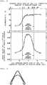
- Fig. 1 shows the relationship between the average grain size of a (Nb, Ti) composite carbide in each ferrite phase, the rate of change in cross-sectional hardness of each steel tube that is formed into cross-sectional shape and then stress-relief annealed, and the rate of reduction in residual stress of the steel tube.
- Fig. 2 shows the relationship between the average grain size of a (Nb, Ti) composite carbide in each ferrite phase, the elongation El of each steel tube (JIS #12 test specimen) that has not yet been formed into cross-sectional shape, and the ratio ( ⁇ B /TS) of the 5 ⁇ 10 5 -cycle fatigue limit ⁇ B to the tensile strength TS of the steel tube.
- the torsional fatigue endurance of the steel tube that is stress-relief annealed is evaluated from the ratio ( ⁇ B /Ts) of the 5 ⁇ 10 5 -cycle fatigue limit to the tensile strength TS of the steel tube.
- the 5 ⁇ 10 5 -cycle fatigue limit of the steel tube is determined in such a manner that a longitudinally central portion of the steel tube is formed so as to have a V-shape in cross section as shown in Fig. 3 (Fig. 11 of Japanese Unexamined Patent Application Publication No.
- the resulting steel tube is stress-relief annealed at 530°C for ten minutes, both end portions of the steel tube are fixed by chucking, and the steel tube is subjected to a torsional fatigue test under completely reversed torsion at 1 Hz for 5 ⁇ 10 5 cycles.
- a steel tube containing a ferrite phase containing a (Nb, Ti) composite carbide with an average grain size outside the range of 2 nm to 40 nm has a rate of change in cross-sectional hardness of less than -15% or a rate of reduction in residual stress of less than 50%.
- a steel tube containing a ferrite phase containing a (Nb, Ti) composite carbide with an average grain size outside the range of 2 nm to 40 nm has a ⁇ B /Ts ratio of less than 0.40 or an elongation El of less than 15%.
- the average grain size of a (Nb, Ti) composite carbide in a ferrite phase is determined as described below.
- a sample for microstructure observation is taken from a steel tube by an extraction replica method. Five fields of view of the sample are observed with a transmission electron microscope (TEM) at a magnification of 100000 times.
- Cementite, which contains no Nb or Ti, TiN, and the like are identified by EDS analysis and then eliminated.
- TEM transmission electron microscope
- the area of each grain of a (Nb, Ti) composite carbide is measured with an image analysis device and the equivalent circle diameter of the grain is calculated from the area thereof.
- the equivalent circle diameters of the grains are arithmetically averaged, whereby the average grain size of the (Nb, Ti) composite carbide is obtained.
- Carbides containing Nb, Ti, Mo, and/or the like are counted as the (Nb, Ti) composite carbide.
- the steel tube according to the present invention preferably has surface properties below. That is, the inner and outer surfaces of the steel tube preferably have an arithmetic average roughness Ra of 2 ⁇ m or less, a maximum-height roughness Rz of 30 ⁇ m or less, and a ten-point average roughness Rz JIS of 20 ⁇ m or less as determined in accordance with JIS B 0601-2001.
- the steel tube does not satisfy the above surface-properties, the steel tube has reduced formability and reduced torsional fatigue endurance because stress-concentrated portions are formed in the steel tube during processing such as forming into cross-sectional shape.
- Steel having the above composition is preferably produced by a known process using a steel converter or the like and then cast into a steel material by a known process such as a continuous casting process.
- the steel material is preferably subjected to a hot-rolling step such that a steel tube material such as a hot-rolled steel strip is obtained.
- the hot-rolling step preferably includes a hot-rolling sub-step of heating the steel material to a temperature of 1160°C to 1320°C and finish-rolling the resulting steel material into the hot-rolled steel strip at a temperature of 760°C to 980°C, an annealing sub-step of annealing the hot-rolled steel strip at a temperature of 650°C to 750°C for 2 s or more, and a coiling sub-step of coiling the resulting hot-rolled steel strip at a temperature of 510°C to 660°C.
- Heating temperature of steel material 1160°C to 1320°C
- the heating temperature of the steel material affects the rate of change in cross-sectional hardness of the steel tube that is stress-relief annealed depending on the solution or precipitation of Nb and Ti in steel and therefore is a factor that is important in preventing the softening thereof.
- the rate of change in cross-sectional hardness of the steel tube that is stress-relief annealed (530°C ⁇ 10 min) is less than -15% and therefore desired torsional fatigue endurance cannot be achieved because coarse precipitates of niobium carbonitride and titanium carbonitride that are formed during continuous casting remain in the steel material without forming solid solutions and therefore coarse grains of a (Nb, Ti) composite carbide are formed in a ferrite phase obtained in a hot-rolled steel sheet.
- the heating temperature of the steel material is preferably limited to a range from 1160°C to 1320°C and more preferably 1200°C to 1300°C.
- the soaking time of the heated steel material is preferably 30 minutes or more.
- Finish-rolling final temperature 760°C to 980°C
- the finish-rolling final temperature of the steel material rolled in the hot-rolling sub-step is a factor that is important in adjusting the microstructure fraction of a ferrite phase in the steel tube material to a predetermined range and to adjust the average grain size of the ferrite phase to a predetermined range to allow the steel tube to have good formability.
- the steel tube has reduced formability because the ferrite phase of the steel tube material has an average grain size of greater than 8 ⁇ m and a microstructure fraction of less than 60 volume percent; the inner and outer surfaces of the steel tube have an arithmetic average roughness Ra of greater than 2 ⁇ m, a maximum-height roughness Rz of greater than 30 ⁇ m, and a ten-point average roughness Rz JIS of greater than 20 ⁇ m; and the steel tube has undesired surface properties and reduced torsional fatigue endurance.
- the finish-rolling final temperature thereof is lower than 760°C, the following problems arise: the steel tube has reduced formability because the ferrite phase of the steel tube material has an average grain size of less than 2 ⁇ m; the (Nb, Ti) composite carbide has an average grain size of greater than 40 nm because of strain-induced precipitation; the rate of change in cross-sectional hardness of the steel tube that is stress-relief annealed (530°C ⁇ 10 min) is less than -15%; and the steel tube cannot have desired torsional fatigue endurance. Therefore, the finish-rolling final temperature thereof is preferably limited to a range from 760°C to 980°C and more preferably 820°C to 880°C. In order to allow the steel tube to have good surface properties, the steel tube material is preferably descaled with high-pressure water at 9.8 MPa (100 Kg/cm 2 ) or more in advance of finish rolling.
- Annealing at a temperature of 650°C to 750°C for 2 s or more
- the hot-rolled steel strip is not coiled directly after finish rolling is finished but is annealed at a temperature of 650°C to 750°C in advance of coiling.
- annealing used herein means cooling at a rate of 20°C/s or less.
- the annealing time of the steel strip, which is annealed at the above temperature is preferable 2 s or more and more preferably 4 s or more.
- the annealing thereof allows the microstructure fraction of the ferrite phase to be 60 volume percent or more, allows the elongation El of the steel tube to be 15% or more as determined using a JIS #12 test specimen, and allows the steel tube to have desired formability.
- Coiling temperature 510°C to 660°C
- the annealed hot-rolled steel strip is coiled into a coil.
- the coiling temperature thereof is preferably within a range from 510°C to 660°C.
- the coiling temperature thereof is a factor that is important in determining the microstructure fraction of the ferrite phase of the hot-rolled steel strip and/or the precipitation of the (Nb, Ti) composite carbide.
- the coiling temperature thereof is lower than 510°C, the ferrite phase cannot have a desired microstructure fraction and therefore the steel tube cannot have desired formability.
- the (Nb, Ti) composite carbide has an average grain size of less than 2 nm and the strength of the steel tube is significantly reduced during stress-relief annealing; hence, the steel tube cannot have desired torsional fatigue endurance.
- the steel tube has reduced formability because the ferrite phase has an average grain size of greater than 8 ⁇ m; a large amount of scales are formed after coiling; the steel strip has undesired surface properties; the inner and outer surfaces of the steel tube have an arithmetic average roughness Ra of greater than 2 ⁇ m; a maximum-height roughness Rz of greater than 30 ⁇ m, and a ten-point average roughness Rz JIS of greater than 20 ⁇ m; and the steel tube has undesired surface properties and reduced torsional fatigue endurance.
- the (Nb, Ti) composite carbide becomes coarse because of Ostwald growth and therefore have an average grain size of greater than 40 nm, the rate of change in cross-sectional hardness of the steel tube that is stress-relief annealed (530°C ⁇ 10 min) is less than -15%, and the steel tube cannot have desired torsional fatigue endurance. Therefore, the coiling temperature thereof is preferably limited to a range from 510°C to 660°C and more preferably 560°C to 620°C.
- the steel material which has the above composition, is subjected to the hot-rolling step under the above conditions, the microstructure and the condition of precipitates are optimized and therefore the steel tube material (hot-rolled steel strip) has excellent surface properties and excellent formability. Furthermore, the steel tube, which is produced from the steel tube material and then stress-relief annealed (530°C ⁇ 10 min), has a small rate of change in cross-sectional hardness and desired excellent torsional fatigue endurance.
- the steel tube material (hot-rolled steel strip) is subjected to an electrically welded tube-making step, whereby a welded steel tube is obtained.
- an electrically welded tube-making step is described below.
- the steel tube material may be used directly after hot rolling and is preferably pickled or shot-blasted such that scales are removed from the steel tube material.
- the steel tube material may be subjected to surface treatment such as zinc plating, aluminum plating, nickel plating, or organic coating treatment.
- the steel tube material that is pickled and/or is then surface-treated is subjected to the electrically welded tube-making step.
- the electrically welded tube-making step includes a sub-step of continuously roll-forming the steel tube material and electrically welding the resulting steel tube material into an electrically welded steel tube.
- the electrically welded steel tube is preferably made at a width reduction of 10% or less (including 0%).
- the width reduction is a factor that is important in achieving desired formability. When the width reduction is greater than 10%, a reduction in formability during tube making is remarkable and therefore desired formability cannot be achieved. Therefore, the width reduction is preferably 10% or less (including 0%) and more preferably 1% or more.
- the high-tensile strength welded steel tube according to the present invention is formed into various shapes and then stress-relief annealed as required, whereby an automobile structural part such as a torsion beam is produced.
- conditions of stress-relief annealing subsequent to forming need not be particularly limited.
- the fatigue life of the tube is remarkably enhanced by stress-relief annealing the tube at a temperature of about 100°C to lower than about 650°C because the diffusion of C prevents the motion of dislocations at about 100°C and the hardness of the tube is remarkably reduced by annealing the tube at about 650°C.
- a 150-200°C coating baking step may be used instead of a stress-relief annealing step.
- the effect of enhancing fatigue life is optimized at a temperature of 460°C to 590°C.
- the soaking time during stress-relief annealing is preferably within a range from 1 s to 5 h and more preferably 2 min to 1 h.
- Steels having compositions shown in Table 1 were produced and then cast into steel materials (slabs) by a continuous casting process. Each steel material was subjected to a hot-rolling step in such a manner that the steel material was heated to about 1250°C, hot-rolled at a finish-rolling temperature of about 860°C, annealed at a temperature 650°C to 750°C for 5 s, and then coiled at a temperature of 590°C, whereby a hot-rolled steel strip (a thickness of about 3 mm) was obtained.
- the hot-rolled steel strip was used as a steel tube material.
- the hot-rolled steel strip was pickled and then slit into pieces having a predetermined width.
- the pieces were continuously roll-formed into open tubes.
- Each open tube was subjected to an electrically welded tube-making step in which the open tube was electrically welded by highfrequency resistance welding, whereby a welded steel tube (an outer diameter ⁇ of 89.1 mm and a thickness of about 3 mm) was prepared.
- Equation (1) the width reduction defined by Equation (1) was 4%.
- Test specimens were taken from the welded steel tubes and then subjected to a microstructure observation test, a precipitate observation test, a tensile test, a surface roughness test, a torsional fatigue test, a low-temperature toughness test, a cross-sectional hardness measurement test subsequent to stress-relief annealing, and a residual stress measurement test subsequent to stress-relief annealing.
- test specimen for microstructure observation was taken from each of the obtained welded steel tubes such that a circumferential cross section of the test specimen could be observed.
- the test specimen was polished, corroded with nital, and then observed for microstructure with a scanning electron microscope (3000 times magnification).
- An image of the test specimen was taken and then used to determine the volume percentage and average grain size (equivalent circle diameter) of a ferrite phase with an image analysis device.
- a test specimen for precipitate observation was taken from each of the obtained welded steel tubes such that a circumferential cross section of the test specimen could be observed.
- a sample for microstructure observation was prepared from the test specimen by an extraction replica method. Five fields of view of the sample were observed with a transmission electron microscope (TEM) at a magnification of 100000 times. Cementite, which contained no Nb or Ti, TiN, and the like were identified by EDS analysis and then eliminated.
- TEM transmission electron microscope
- Cementite which contained no Nb or Ti, TiN, and the like were identified by EDS analysis and then eliminated.
- the equivalent circle diameters of the grains were arithmetically averaged, whereby the average grain size of the (Nb, Ti) composite carbide was obtained.
- Carbides containing Nb, Ti, Mo, and/or the like were counted as the (Nb, Ti) composite carbide.
- a JIS #12 test specimen was cut out from each of the obtained welded steel tubes in accordance with JIS Z 2201 such that an L-direction was a tensile direction.
- the specimen was subjected to a tensile test in accordance with JIS Z 2241, measured for tensile properties (tensile strength TS, yield strength YS, and elongation El), and then evaluated for strength and formability.
- the inner and outer surfaces of each of the obtained welded steel tubes were measured for surface roughness with a probe-type roughness meter in accordance with JIS B 0601-2001, whereby a roughness curve was obtained and roughness parameters, that is, the arithmetic average roughness Ra, maximum-height roughness Rz, and ten-point average roughness Rz JIS of each tube were determined.
- the roughness curve was obtained in such a manner that the tube was measured in the circumferential direction (C-direction) of the tube and a low cutoff value of 0.8 mm and an evaluation length of 4 mm were used. A larger one of parameters of the inner and outer surfaces thereof was used as a typical value.
- test material (a length of 1500 mm) was taken from each of the obtained welded steel tubes. A longitudinally central portion of the steel tube was formed so as to have a V-shape in cross section as shown in Fig. 3 (Fig. 11 of Japanese Unexamined Patent Application Publication No. 2001-321846 ) and then stress-relief annealed at 530°C for ten minutes. The test material was subjected to a torsional fatigue in such a manner that both end portions thereof were fixed by chucking.
- the torsional fatigue test was performed under completely reversed torsion at 1 Hz, the level of a stress was varied, and the number N of cycles performed until breakage occurred at a load stress S was determined.
- the 5 ⁇ 10 5 -cycle fatigue limit ⁇ B (MPa) of the test material was determined from an S-N diagram obtained by the test.
- the torsional fatigue endurance of the test material was evaluated from the ratio ⁇ B /Ts (wherein TS represents the tensile stress (MPa) of the steel tube).
- the load stress was measured in such a manner that a dummy piece was first subjected to a torsion test, the location of a fatigue crack was thereby identified, and a triaxial strain gauge was then attached to the location thereof.
- Test materials (a length of 1500 mm) were taken from each of the obtained welded steel tubes.
- the test materials were formed into cross-sectional shape and stress-relief annealed under the same conditions as those used to treat the test material for the torsional fatigue test.
- a flat portion of one of the unannealed test materials was expanded such that the circumferential direction (C-direction) of a corresponding one of the tubes corresponds to the length direction of this test material.
- a flat portion of one of the stress-relief annealed test materials was expanded such that the circumferential direction (C-direction) of a corresponding one of the tubes corresponds to the length direction of this test material.
- a V-notched test specimen (1/4-sized) was cut out from each of the flat portions in accordance with JIS Z 2242, subjected to a Charpy impact test, and then measured for fracture appearance transition temperature vTrs, whereby the specimen was evaluated for low-temperature toughness.
- Test materials were formed into cross-sectional shape under the same conditions as those used to treat the test material for the torsional fatigue test. Some of the test materials were stress-relief annealed (530°C ⁇ 10 min). Test specimens for cross-sectional hardness measurement were taken from fatigue crack-corresponding portions of the unannealed test materials and those of the annealed test materials and then measured for Vickers hardness with a Vickers hardness meter (a load of 10 kg). Three portions of each test material that were each located at a depth equal to 1/4, 1/2, or 3/4 of the thickness thereof were measured for thickness and obtained measurements were averaged, whereby the cross-sectional hardness of the test material subjected or unsubjected to stress-relief annealing (SR) was obtained.
- SR stress-relief annealing
- Examples (Steel Tube Nos. 1 to 10) of the present invention provide high-tensile strength welded steel tubes having high strength and excellent formability.
- the high-tensile strength welded steel tubes each contain a ferrite phase having a microstructure fraction of 60 volume percent or more and an average grain size of 2 ⁇ m to 8 ⁇ m, have a structure containing a (Nb, Ti) composite carbide having an average grain size of 2 nm to 40 nm, and have a yield strength YS of greater than 660 MPa.
- the JIS #12 test specimen taken from each of the high-tensile strength welded steel tubes has an elongation El of 15% or more.
- the high-tensile strength welded steel tubes that are stress-relief annealed have a rate of change in cross-sectional hardness of -15% or more, a rate of reduction in residual stress of 50% or more, and a ⁇ B /Ts ratio of 0.40 or more, wherein ⁇ B represents the 5 ⁇ 10 5 -cycle fatigue limit of each high-tensile strength welded steel tube tested by the torsional fatigue test and TS represents the tensile strength thereof. Therefore, the high-tensile strength welded steel tubes have excellent torsional fatigue endurance.
- the high-tensile strength welded steel tubes that are formed into cross-sectional shape and the high-tensile strength welded steel tubes that are formed into cross-sectional shape and then stress-relief annealed have a fracture appearance transition temperature vTrs of -40°C or less and therefore are excellent in low-temperature toughness.
- comparative examples in which the content of a steel component is outside the scope of the present invention have microstructures and the like outside the scope of the present invention.
- the steel tubes that are stress-relief annealed have low torsional fatigue endurance.
- the steel tubes that are formed into cross-sectional shape have low low-temperature toughness.
- the steel tubes that are stress-relief annealed have low low-temperature toughness.
- Comparative examples in which the content of C, Mn, Ti, Nb, N, V, or Cr is high and therefore is outside the scope of the present invention have an elongation El of less than 15% and therefore are insufficient in ductility.
- the comparative examples have a ⁇ B /Ts ratio of less than 0.40 and therefore are low in torsional fatigue endurance.
- the comparative examples have a fracture appearance transition temperature vTrs of higher than -40°C and therefore are low in low-temperature toughness. Comparative examples (Steel Tube Nos.
- Comparative examples (Steel Tube Nos. 29, 30, and 31) in which the content of Mo, B, or Cu is high and therefore is outside the scope of the present invention have an elongation El of less than 15% and therefore are insufficient in ductility.
- the comparative examples have a rate of reduction in residual stress of less than 50% after being stress-relief annealed and a ⁇ B /Ts ratio of less than 0.40 and therefore are low in torsional fatigue endurance.
- Comparative examples in which the content of Si, Al, S, or O is high and therefore is outside the scope of the present invention have a ⁇ B /Ts ratio of less than 0.40 after being stress-relief annealed and therefore are low in torsional fatigue endurance.
- a comparative example (Steel Tube No. 23) in which the content of P is high and therefore is outside the scope of the present invention has an elongation El of less than 15% and therefore is insufficient in ductility. Furthermore, the comparative example has a fracture appearance transition temperature vTrs of higher than -40°C and therefore is low in low-temperature toughness.
- Steel Tube Nos. 1 to 31 except Steel Tube No. 14 have an arithmetic average roughness Ra of 0.7 ⁇ m to 1.8 ⁇ m, a maximum-height roughness Rz of 10 ⁇ m to 22 ⁇ m, and a ten-point average roughness Rz JIS of 7 ⁇ m to 15 ⁇ m and therefore are good in surface roughness.
- Steel Tube No. 14 has an arithmetic average roughness Ra of 1.6 ⁇ m, a maximum-height roughness Rz of 27 ⁇ m, and a ten-point average roughness Rz JIS of 21 ⁇ m. That is, the arithmetic average roughness and maximum-height roughness of Steel Tube No. 14 are good; however, the ten-point average roughness thereof is high.
- Test specimens were taken from the obtained welded steel tubes in the same manner as that described in Example 1 and then subjected to a microstructure observation test, a precipitate observation test, a tensile test, a surface roughness test, a torsional fatigue test, a low-temperature toughness test, a cross-sectional hardness measurement test subsequent to stress-relief annealing, and a residual stress measurement test subsequent to stress-relief annealing.
- Examples (Steel Tube Nos. 33, 36, 39, 41 to 43, and 45 to 51) of the present invention provide high-tensile strength welded steel tubes having high strength and excellent formability.
- the high-tensile strength welded steel tubes each contain a ferrite phase having a microstructure fraction of 60 volume percent or more and an average grain size of 2 ⁇ m to 8 ⁇ m, have a structure containing a (Nb, Ti) composite carbide having an average grain size of 2 nm to 40 nm, and have a yield strength YS of greater than 660 MPa.
- a JIS #12 test specimen taken from each of the high-tensile strength welded steel tubes has an elongation El of 15% or more.
- the high-tensile strength welded steel tubes that are stress-relief annealed have a rate of change in cross-sectional hardness of -15% or more, a rate of reduction in residual stress of 50% or more, and a ⁇ B /Ts ratio of 0.40 or more after being stress-relief annealed (530°C x 10 min), wherein ⁇ B represents the 5 x 10 5 -cycle fatigue limit of each high-tensile strength welded steel tube tested by a torsional fatigue test and TS represents the tensile strength thereof. Therefore, the high-tensile strength welded steel tubes have excellent torsional fatigue endurance.
- the high-tensile strength welded steel tubes that are formed into cross-sectional shape and the high-tensile strength welded steel tubes that are formed into cross-sectional shape and then stress-relief annealed have a fracture appearance transition temperature vTrs of -40°C or less and therefore are excellent in low-temperature toughness.
- comparative examples in which conditions of the hot-rolling step of rolling each steel material or conditions of the electrically welded tube-making step of making each steel tube are outside the scope of the present invention are low in strength, formability, torsional fatigue endurance after being stress-relief annealed, low-temperature toughness after being formed into cross-sectional shape, or low-temperature toughness after being stress-relief annealed.
- Comparative examples in which annealing conditions and a coiling temperature in the hot-rolling step are outside the scope of the present invention have high strength, an elongation El of less than 15%, and a ⁇ B /Ts ratio of less than 0.40. Therefore, the comparative examples have low formability and low torsional fatigue endurance after being stress-relief annealed.
- Comparative examples in which a finish-rolling final temperature and coiling temperature in the hot-rolling step are high and therefore are outside the scope of the present invention have an elongation El of less than 15% and a ⁇ B /Ts ratio of less than 0.40 and do not meet the following requirements: an arithmetic average roughness Ra of 2 ⁇ m or less, a maximum-height roughness Rz of 30 ⁇ m or less, and a ten-point average roughness Rz JIS of 20 ⁇ m or less. Therefore, the comparative examples have low formability, insufficient surface properties, and low torsional fatigue endurance after being stress-relief annealed.
- Comparative examples in which the heating temperature of each steel material and a width reduction in the electrically welded tube-making step are high and therefore are outside the scope of the present invention have a ⁇ B /Ts ratio of less than 0.40 and a fracture appearance transition temperature vTrs of higher than -40°C. Therefore, the comparative examples have low torsional fatigue endurance and low low-temperature toughness after being stress-relief annealed.
- Comparative examples in which the heating temperature and finish-rolling final temperature of each steel material are low and therefore are outside the scope of the present invention have a ⁇ B /Ts ratio of less than 0.40 and therefore are low in torsional fatigue endurance after being stress-relief annealed.
Landscapes
- Chemical & Material Sciences (AREA)
- Engineering & Computer Science (AREA)
- Mechanical Engineering (AREA)
- Materials Engineering (AREA)
- Metallurgy (AREA)
- Organic Chemistry (AREA)
- Physics & Mathematics (AREA)
- Thermal Sciences (AREA)
- Crystallography & Structural Chemistry (AREA)
- Heat Treatment Of Sheet Steel (AREA)
- Heat Treatment Of Steel (AREA)
Claims (3)
- Tube en acier soudé de résistance élevée à la traction, ayant d'excellentes ténacité à basse température, aptitude au formage et endurance à la fatigue de torsion après avoir été soumis à un recuit de libération des contraintes, destiné à des pièces structurales d'automobiles, le tube ayant une composition constituée de 0,03 % à 0,24 % de C, 0,002 % à 0,95 % de Si, 1,01 % à 1,99 % de Mn et 0,01 % à 0,08 % d'Al, laquelle contient en outre 0,041 % à 0,150 % de Ti et 0,017 % à 0,150 % de Nb, de telle sorte que la somme de la teneur en Ti et de celle de Nb vaut 0,08 % ou plus, et laquelle contient en outre 0,019 % ou moins de P, 0,020 % ou moins de S, 0,010 % ou moins de N et 0,005 % ou moins de O sur une base de masse, éventuellement en outre un élément ou plus choisi dans le groupe constitué de 0,001 % à 0,150 % de V, 0,001 % à 0,150 % de W, 0,001 % à 0,45 % de Cr, 0,001 % à 0,24 % de Mo, 0,0001 % à 0,0009 % de B, 0,001 % à 0,45 % de Cu et 0,001 % à 0,45 % de Ni et/ou 0,0001 % à 0,005 % de Ca sur une base de masse, le reste étant du Fe et des impuretés inévitables, P, S, N et O étant des impuretés ; une microstructure contenant une phase ferritique et une seconde phase autre que la phase ferritique ; et une limite élastique supérieure à 660 MPa, la phase ferritique ayant une taille de grain moyenne de 2 µm à 8 µm dans une section de coupe circonférentielle et une fraction de microstructure de 60 pourcent en volume ou plus et contenant un précipité d'un carbure composite de (Nb, Ti) ayant une taille de grain moyenne de 2 à 40 nm.
- Tube en acier soudé de résistance élevée à la traction selon la revendication 1, dans lequel les surfaces intérieure et extérieure du tube ont une rugosité moyenne arithmétique Ra de 2 µm ou moins, une rugosité de hauteur maximale Rz de 30 µm ou moins et une rugosité moyenne sur dix points RzJIS de 20 µm ou moins.
- Procédé de fabrication d'un tube en acier soudé de résistance élevée à la traction ayant une limite d'élasticité supérieure à 660 MPa, une excellente ténacité à basse température, une excellente aptitude au formage et une excellente endurance à la fatigue de torsion après avoir été soumis à un recuit de libération des contraintes, destiné à des pièces structurales d'automobiles, le procédé comprenant une étape de fabrication de tube soudé électriquement consistant à former un matériau pour tube en acier en forme de tube en acier soudé, le matériau pour tube soudé étant une bande d'acier laminée à chaud qui est obtenue de telle manière qu'un matériau d'acier est soumis à une étape de laminage à chaud incluant une sous-étape de laminage à chaud consistant à chauffer le matériau d'acier à une température de 1160 °C à 1320 °C et ensuite effectuer un laminage de finissage du matériau d'acier à une température de 760 °C à 980 °C, une sous-étape de recuit consistant à recuire le matériau d'acier laminé à une température de 650 °C à 750 °C pendant 2 s ou plus, et une sous-étape de bobinage consistant à bobiner le matériau d'acier recuit à une température de 510 °C à 660 °C ; le matériau d'acier a une composition selon la revendication 1 ; l'étape de fabrication de tube soudé électriquement inclut une étape de fabrication de tube consistant à profiler en continu le matériau pour tube en acier avec une réduction de largeur de 10 % ou moins puis à souder électriquement le matériau pour tube en acier en tube en acier soudé ; et la réduction de largeur du matériau pour tube en acier est définie par l'équation suivante :

Applications Claiming Priority (2)
| Application Number | Priority Date | Filing Date | Title |
|---|---|---|---|
| JP2006185810A JP4466619B2 (ja) | 2006-07-05 | 2006-07-05 | 自動車構造部材用高張力溶接鋼管およびその製造方法 |
| PCT/JP2007/062651 WO2008004453A1 (fr) | 2006-07-05 | 2007-06-19 | Tube en acier soudé de haute tension pour élément structural automobile et son procédé de fabrication |
Publications (3)
| Publication Number | Publication Date |
|---|---|
| EP2050833A1 EP2050833A1 (fr) | 2009-04-22 |
| EP2050833A4 EP2050833A4 (fr) | 2015-04-22 |
| EP2050833B1 true EP2050833B1 (fr) | 2017-04-19 |
Family
ID=38894424
Family Applications (1)
| Application Number | Title | Priority Date | Filing Date |
|---|---|---|---|
| EP07767459.6A Active EP2050833B1 (fr) | 2006-07-05 | 2007-06-19 | Tube en acier soudé de haute tension pour élément structural automobile et son procédé de fabrication |
Country Status (7)
| Country | Link |
|---|---|
| US (1) | US7887649B2 (fr) |
| EP (1) | EP2050833B1 (fr) |
| JP (1) | JP4466619B2 (fr) |
| KR (1) | KR100996395B1 (fr) |
| CN (1) | CN101484602B (fr) |
| CA (1) | CA2656637C (fr) |
| WO (1) | WO2008004453A1 (fr) |
Families Citing this family (50)
| Publication number | Priority date | Publication date | Assignee | Title |
|---|---|---|---|---|
| JP4502947B2 (ja) * | 2005-12-27 | 2010-07-14 | 株式会社神戸製鋼所 | 溶接性に優れた鋼板 |
| JP4910694B2 (ja) * | 2006-12-28 | 2012-04-04 | Jfeスチール株式会社 | 自動車構造部材用高張力溶接鋼管及びその製造方法 |
| DE102007030207A1 (de) * | 2007-06-27 | 2009-01-02 | Benteler Automobiltechnik Gmbh | Verwendung einer hochfesten Stahllegierung zur Herstellung von Strahlrohren mit hoher Festigkeit und guter Umformbarkeit |
| JP5125601B2 (ja) * | 2008-02-26 | 2013-01-23 | Jfeスチール株式会社 | 自動車構造部材用高張力溶接鋼管およびその製造方法 |
| JP5282449B2 (ja) * | 2008-06-03 | 2013-09-04 | Jfeスチール株式会社 | 成形性と耐疲労特性に優れた高張力鋼材およびその製造方法 |
| JP4998755B2 (ja) * | 2009-05-12 | 2012-08-15 | Jfeスチール株式会社 | 高強度熱延鋼板およびその製造方法 |
| JP2011006781A (ja) | 2009-05-25 | 2011-01-13 | Nippon Steel Corp | 低サイクル疲労特性に優れた自動車足回り部品とその製造方法 |
| JP5573003B2 (ja) * | 2009-05-29 | 2014-08-20 | Jfeスチール株式会社 | 自動車部材用高張力溶接鋼管 |
| FI122143B (fi) * | 2009-10-23 | 2011-09-15 | Rautaruukki Oyj | Menetelmä korkealujuuksisen sinkityn muotovalmisteen valmistamiseksi sekä muotovalmiste |
| US20130160889A1 (en) * | 2010-03-24 | 2013-06-27 | Jfe Steel Corporation | High-strength electric resistance welded steel tube and production method therefor |
| US20110253265A1 (en) * | 2010-04-15 | 2011-10-20 | Nisshin Steel Co., Ltd. | Quenched and tempered steel pipe with high fatigue life, and its manufacturing method |
| KR101160016B1 (ko) * | 2010-09-29 | 2012-06-25 | 현대제철 주식회사 | 가공성이 우수한 하이드로포밍용 고강도 열연강판 및 그 제조 방법 |
| US20120103459A1 (en) * | 2010-10-28 | 2012-05-03 | Nisshin Steel Co., Ltd. | High fatigue service life quenching/tempering steel tube and manufacturing method therefor |
| CN102828112B (zh) * | 2011-06-14 | 2015-05-06 | 鞍钢股份有限公司 | 一种低成本高强度冷成型热连轧钢带及其制造方法 |
| CN105648311B (zh) * | 2011-08-09 | 2018-03-30 | 新日铁住金株式会社 | 在低温下的冲击能吸收特性和耐haz软化特性优异的高屈服比热轧钢板 |
| JP5316634B2 (ja) * | 2011-12-19 | 2013-10-16 | Jfeスチール株式会社 | 加工性に優れた高強度鋼板およびその製造方法 |
| CN103753115A (zh) * | 2011-12-31 | 2014-04-30 | 东莞市飞新达精密机械科技有限公司 | 一种带开口长槽的板类零件的加工方法 |
| JP5370503B2 (ja) * | 2012-01-12 | 2013-12-18 | 新日鐵住金株式会社 | 低合金鋼 |
| JP5909143B2 (ja) * | 2012-04-13 | 2016-04-26 | 株式会社神戸製鋼所 | 熱延鋼板のmag溶接方法および熱延鋼板のmig溶接方法 |
| FR2991213B1 (fr) * | 2012-06-05 | 2015-07-03 | Alstom Hydro France | Procede de soudage de deux bords d'une ou plusieurs pieces en acier l'un a l'autre et conduite forcee obtenue par un tel procede. |
| KR101400586B1 (ko) * | 2012-09-27 | 2014-05-27 | 현대제철 주식회사 | 강판 및 그 제조 방법 |
| CN102991449B (zh) * | 2012-11-08 | 2016-04-06 | 上海冠驰汽车安全技术有限公司 | 一种有关汽车安全带的限力扭杆 |
| MX2015006016A (es) * | 2012-11-14 | 2015-08-07 | Jfe Steel Corp | Miembro de absorcion de energia de colision para un vehiculo y metodo para la fabricacion del mismo. |
| EP3045554B1 (fr) * | 2013-09-10 | 2018-04-18 | Kabushiki Kaisha Kobe Seiko Sho (Kobe Steel, Ltd.) | Tôle d'acier pour formage à chaud à la presse, article moulé à la presse et procédé de fabrication d'un article moulé à la presse |
| CN105658834A (zh) * | 2013-09-19 | 2016-06-08 | 塔塔钢铁艾默伊登有限责任公司 | 用于热成形的钢 |
| MX2017005170A (es) * | 2014-10-23 | 2017-07-27 | Jfe Steel Corp | Tubo de acero soldado de alta resistencia para inflador de bolsas de aire y metodo para la fabricacion del mismo. |
| JP6789611B2 (ja) * | 2015-01-22 | 2020-11-25 | 臼井国際産業株式会社 | ガソリン直噴用フューエルレールの製造方法 |
| JP6782060B2 (ja) * | 2015-01-22 | 2020-11-11 | 臼井国際産業株式会社 | フューエルレールの製造方法 |
| CN105986190A (zh) * | 2015-02-25 | 2016-10-05 | 鞍钢股份有限公司 | 一种高强高韧性起重机臂架用管及其制造方法 |
| EP3246427B1 (fr) * | 2015-03-06 | 2018-12-12 | JFE Steel Corporation | Tuyau en acier soudé par résistance électrique à haute résistance et procédé de fabrication s'y rapportant |
| CA2982068C (fr) * | 2015-04-08 | 2020-01-14 | Nippon Steel & Sumitomo Metal Corporation | Tole d'acier pour traitement thermique |
| JP6179584B2 (ja) * | 2015-12-22 | 2017-08-16 | Jfeスチール株式会社 | 曲げ性に優れた高強度鋼板およびその製造方法 |
| EP3356109B1 (fr) * | 2016-01-25 | 2022-03-09 | Alexander Christ | Châssis de véhicule avec au moins une pièce structurale en résine cellulaire et son procédé de fabrication |
| KR101822292B1 (ko) | 2016-08-17 | 2018-01-26 | 현대자동차주식회사 | 고강도 특수강 |
| KR101822295B1 (ko) | 2016-09-09 | 2018-01-26 | 현대자동차주식회사 | 고강도 특수강 |
| EP3521475A4 (fr) * | 2016-10-03 | 2020-03-18 | Nippon Steel & Sumitomo Metal Corporation | Tuyau en acier soudé par résistance électrique destiné à une poutre de torsion |
| US11332812B2 (en) | 2016-10-24 | 2022-05-17 | Jfe Steel Corporation | Electric resistance welded steel tubes for high-strength thin hollow stabilizers, and methods for manufacturing the same |
| KR101917454B1 (ko) * | 2016-12-22 | 2018-11-09 | 주식회사 포스코 | 고강도 고인성 후강판 및 이의 제조방법 |
| MX2019011941A (es) * | 2017-04-07 | 2019-11-28 | Jfe Steel Corp | Elemento de acero, laminas de acero laminadas en caliente para elementos de acero y metodo de produccion de los mismos. |
| CN110494583B (zh) | 2017-04-07 | 2021-10-26 | 杰富意钢铁株式会社 | 钢构件、所述钢构件用的热轧钢板和它们的制造方法 |
| CN107236900A (zh) * | 2017-04-25 | 2017-10-10 | 河钢股份有限公司承德分公司 | 含钒700MPa级汽车传动轴用热轧钢带、生产方法及应用 |
| KR102020417B1 (ko) * | 2017-12-22 | 2019-09-10 | 주식회사 포스코 | 충격인성이 우수한 용접강관용 강재 및 그 제조방법 |
| CN109023049A (zh) * | 2018-08-10 | 2018-12-18 | 首钢集团有限公司 | 一种托辊用焊接钢管及其制造方法 |
| CN113631735B (zh) * | 2019-03-29 | 2023-04-11 | 日本制铁株式会社 | 中空稳定器用电焊钢管和中空稳定器、以及其制造方法 |
| EP4095280A4 (fr) * | 2020-04-02 | 2022-12-28 | JFE Steel Corporation | Tuyau en acier électrosoudé et son procédé de fabrication |
| CN111721647B (zh) * | 2020-06-24 | 2021-12-28 | 四川大学 | 一种低周疲劳测试数据处理与内应力评估方法 |
| CN111690882A (zh) * | 2020-07-29 | 2020-09-22 | 攀钢集团研究院有限公司 | 660MPa级高耐蚀耐候钢及其制备方法 |
| CN111961967B (zh) * | 2020-07-31 | 2021-09-21 | 天津钢铁集团有限公司 | 小压缩比厚规格控轧型q345gje建筑结构用钢板及其生产方法 |
| KR102443927B1 (ko) * | 2020-08-26 | 2022-09-19 | 주식회사 포스코 | 용접부 충격 인성이 우수한 열연강판 및 이의 제조방법 |
| WO2024070052A1 (fr) * | 2022-09-30 | 2024-04-04 | 日本製鉄株式会社 | Plaque d'acier |
Family Cites Families (16)
| Publication number | Priority date | Publication date | Assignee | Title |
|---|---|---|---|---|
| JP2588648B2 (ja) | 1991-07-02 | 1997-03-05 | 新日本製鐵株式会社 | 超高張力電縫鋼管の製造方法 |
| JP2814882B2 (ja) | 1992-07-27 | 1998-10-27 | 住友金属工業株式会社 | 高強度高延性電縫鋼管の製造方法 |
| BR9806104A (pt) * | 1997-06-26 | 1999-08-31 | Kawasaki Steel Co | Tubo de aço de granulação superfina e processo para a produção do mesmo. |
| JP4272284B2 (ja) * | 1998-12-11 | 2009-06-03 | 日新製鋼株式会社 | 疲労耐久性に優れた中空スタビライザー用電縫溶接鋼管 |
| JP2000204442A (ja) * | 1999-01-14 | 2000-07-25 | Sumitomo Metal Ind Ltd | 電縫溶接部靱性に優れた高強度電縫鋼管 |
| JP3750521B2 (ja) | 2000-03-09 | 2006-03-01 | トヨタ自動車株式会社 | 異形断面筒状体の製造方法及びトーションビーム用アクスルビーム |
| JP4608739B2 (ja) * | 2000-06-14 | 2011-01-12 | Jfeスチール株式会社 | 自動車ドア補強用鋼管の製造方法 |
| WO2002036840A1 (fr) * | 2000-10-31 | 2002-05-10 | Nkk Corporation | Tole d"acier laminee a chaud presentant une resistance elevee a la traction et procede de fabrication |
| DE60224262T2 (de) * | 2001-03-07 | 2008-12-11 | Nippon Steel Corp. | Elektrogeschweisstes stahlrohr für hohlstabilisator |
| WO2003066921A1 (fr) * | 2002-02-07 | 2003-08-14 | Jfe Steel Corporation | Tole d'acier haute resistance et procede de production |
| JP4007050B2 (ja) | 2002-04-26 | 2007-11-14 | Jfeスチール株式会社 | 加工性と疲労特性に優れた高張力溶接鋼管およびその製造方法、ならびに溶接鋼管素材用鋼帯 |
| JP3925290B2 (ja) * | 2002-04-26 | 2007-06-06 | Jfeスチール株式会社 | 加工性と靱性に優れた高張力溶接鋼管およびその製造方法 |
| JP3925291B2 (ja) * | 2002-04-26 | 2007-06-06 | Jfeスチール株式会社 | 加工性と溶接部の材質均一性に優れた高張力溶接鋼管およびその製造方法、ならびに溶接鋼管素材用鋼帯 |
| JP4475424B2 (ja) * | 2003-05-28 | 2010-06-09 | 住友金属工業株式会社 | 埋設拡管用油井鋼管 |
| EP1662014B1 (fr) * | 2003-06-12 | 2018-03-07 | JFE Steel Corporation | Plaque d'acier et tube d'acier soude ayant un faible rapport d'ecoulement, une resistance elevee et une resilience elevee, et procede pour les produire |
| JP4735315B2 (ja) * | 2006-02-15 | 2011-07-27 | Jfeスチール株式会社 | 自動車構造部材用高張力溶接鋼管およびその製造方法 |
-
2006
- 2006-07-05 JP JP2006185810A patent/JP4466619B2/ja not_active Expired - Fee Related
-
2007
- 2007-06-19 EP EP07767459.6A patent/EP2050833B1/fr active Active
- 2007-06-19 CA CA2656637A patent/CA2656637C/fr active Active
- 2007-06-19 US US12/307,439 patent/US7887649B2/en active Active
- 2007-06-19 WO PCT/JP2007/062651 patent/WO2008004453A1/fr active Application Filing
- 2007-06-19 KR KR1020087032204A patent/KR100996395B1/ko active IP Right Grant
- 2007-06-19 CN CN2007800254627A patent/CN101484602B/zh active Active
Non-Patent Citations (1)
| Title |
|---|
| None * |
Also Published As
| Publication number | Publication date |
|---|---|
| CA2656637A1 (fr) | 2008-01-10 |
| US7887649B2 (en) | 2011-02-15 |
| EP2050833A4 (fr) | 2015-04-22 |
| CN101484602A (zh) | 2009-07-15 |
| KR100996395B1 (ko) | 2010-11-24 |
| CA2656637C (fr) | 2013-08-20 |
| JP2008013808A (ja) | 2008-01-24 |
| EP2050833A1 (fr) | 2009-04-22 |
| WO2008004453A1 (fr) | 2008-01-10 |
| US20090277544A1 (en) | 2009-11-12 |
| KR20090016746A (ko) | 2009-02-17 |
| JP4466619B2 (ja) | 2010-05-26 |
| CN101484602B (zh) | 2011-08-03 |
Similar Documents
| Publication | Publication Date | Title |
|---|---|---|
| EP2050833B1 (fr) | Tube en acier soudé de haute tension pour élément structural automobile et son procédé de fabrication | |
| EP2258886B1 (fr) | Tôle d'acier galvanisée par immersion à chaud, à haute résistance, présentant une excellente aptitude au traitement et son procédé de fabrication | |
| EP1693476B1 (fr) | Produit en acier pour element structurel d'automobile et procede de fabrication dudit produit | |
| EP2735623B1 (fr) | Feuille d'acier à haute résistance pour le formage à chaud et son procédé de fabrication | |
| EP2184373B1 (fr) | Tôle d'acier laminée à chaud épaisse ayant une excellente aptitude à la transformation et une excellente résistance/solidité après traitement thermique et procédé pour la production de la tôle d'acier | |
| JP4735315B2 (ja) | 自動車構造部材用高張力溶接鋼管およびその製造方法 | |
| EP2759613B1 (fr) | Tôle en acier laminée à chaud de force de traction élevée, et procédé de fabrication de celle-ci | |
| EP2453032A1 (fr) | Tôle d acier à haute résistance et procédé de fabrication associé | |
| EP3733898B1 (fr) | Tôle d'acier laminée à froid à haute résistance et son procédé de fabrication | |
| EP2942416A1 (fr) | Feuille d'acier à haute résistance avec une excellente aptitude au façonnage et son procédé de fabrication | |
| EP3399064B1 (fr) | Tôle en acier laminée à froid hautement résistante | |
| JP5187003B2 (ja) | 成形性と耐疲労特性に優れた高張力鋼材およびその製造方法 | |
| EP2586886A1 (fr) | Tôle d'acier laminée à chaud à haute tension présentant une excellente malléabilité, et son procédé de production | |
| EP3342891B1 (fr) | Tôle d'acier | |
| JP4910694B2 (ja) | 自動車構造部材用高張力溶接鋼管及びその製造方法 | |
| EP3733897B1 (fr) | Tôle d'acier laminée à froid à haute résistance et son procédé de fabrication | |
| EP2765211A1 (fr) | Tôle en acier laminée à chaud de force de traction élevée, et procédé de fabrication de celle-ci | |
| EP3093360A1 (fr) | Élément façonné à chaud et son procédé de fabrication | |
| EP2792762A1 (fr) | Tôle d'acier laminée à froid haute résistance et à rapport d'élasticité élevé et procédé permettant de produire cette dernière | |
| EP2578714B1 (fr) | Tôle d'acier haute résistance laminée à chaud, et son procédé de production | |
| EP4083241A1 (fr) | Tôle d'acier laminée à chaud | |
| JP5125601B2 (ja) | 自動車構造部材用高張力溶接鋼管およびその製造方法 | |
| EP3346018B1 (fr) | Tôle d'acier | |
| JP2011038155A (ja) | 成形性と耐ねじり疲労特性に優れた自動車足回り部材用高張力鋼材及びその製造方法 | |
| JP7359331B1 (ja) | 高強度鋼板およびその製造方法 |
Legal Events
| Date | Code | Title | Description |
|---|---|---|---|
| PUAI | Public reference made under article 153(3) epc to a published international application that has entered the european phase |
Free format text: ORIGINAL CODE: 0009012 |
|
| 17P | Request for examination filed |
Effective date: 20090112 |
|
| AK | Designated contracting states |
Kind code of ref document: A1 Designated state(s): AT BE BG CH CY CZ DE DK EE ES FI FR GB GR HU IE IS IT LI LT LU LV MC MT NL PL PT RO SE SI SK TR |
|
| AX | Request for extension of the european patent |
Extension state: AL BA HR MK RS |
|
| DAX | Request for extension of the european patent (deleted) | ||
| RBV | Designated contracting states (corrected) |
Designated state(s): DE FR GB |
|
| RA4 | Supplementary search report drawn up and despatched (corrected) |
Effective date: 20150319 |
|
| RIC1 | Information provided on ipc code assigned before grant |
Ipc: C22C 38/58 20060101ALI20150313BHEP Ipc: C21D 8/10 20060101ALI20150313BHEP Ipc: C21D 8/02 20060101ALI20150313BHEP Ipc: B21C 37/08 20060101ALI20150313BHEP Ipc: C22C 38/00 20060101AFI20150313BHEP Ipc: C22C 38/14 20060101ALI20150313BHEP |
|
| 17Q | First examination report despatched |
Effective date: 20160126 |
|
| GRAP | Despatch of communication of intention to grant a patent |
Free format text: ORIGINAL CODE: EPIDOSNIGR1 |
|
| RIN1 | Information on inventor provided before grant (corrected) |
Inventor name: TOYODA, SHUNSUKE Inventor name: SATO, AKIO Inventor name: KAWABATA, YOSHIKAZU Inventor name: SAKATA, KEI Inventor name: GUNJI, MAKIO Inventor name: HASHIMOTO, YUJI Inventor name: ARATANI, MASATOSHI Inventor name: SUZUKI, KOJI Inventor name: SAWAKI, TETSURO |
|
| INTG | Intention to grant announced |
Effective date: 20160802 |
|
| GRAJ | Information related to disapproval of communication of intention to grant by the applicant or resumption of examination proceedings by the epo deleted |
Free format text: ORIGINAL CODE: EPIDOSDIGR1 |
|
| INTC | Intention to grant announced (deleted) | ||
| GRAP | Despatch of communication of intention to grant a patent |
Free format text: ORIGINAL CODE: EPIDOSNIGR1 |
|
| INTG | Intention to grant announced |
Effective date: 20161221 |
|
| GRAS | Grant fee paid |
Free format text: ORIGINAL CODE: EPIDOSNIGR3 |
|
| GRAA | (expected) grant |
Free format text: ORIGINAL CODE: 0009210 |
|
| AK | Designated contracting states |
Kind code of ref document: B1 Designated state(s): DE FR GB |
|
| REG | Reference to a national code |
Ref country code: GB Ref legal event code: FG4D |
|
| REG | Reference to a national code |
Ref country code: DE Ref legal event code: R096 Ref document number: 602007050677 Country of ref document: DE |
|
| REG | Reference to a national code |
Ref country code: FR Ref legal event code: PLFP Year of fee payment: 11 |
|
| REG | Reference to a national code |
Ref country code: DE Ref legal event code: R097 Ref document number: 602007050677 Country of ref document: DE |
|
| PLBE | No opposition filed within time limit |
Free format text: ORIGINAL CODE: 0009261 |
|
| STAA | Information on the status of an ep patent application or granted ep patent |
Free format text: STATUS: NO OPPOSITION FILED WITHIN TIME LIMIT |
|
| 26N | No opposition filed |
Effective date: 20180122 |
|
| REG | Reference to a national code |
Ref country code: FR Ref legal event code: PLFP Year of fee payment: 12 |
|
| PGFP | Annual fee paid to national office [announced via postgrant information from national office to epo] |
Ref country code: FR Payment date: 20230510 Year of fee payment: 17 Ref country code: DE Payment date: 20230502 Year of fee payment: 17 |
|
| PGFP | Annual fee paid to national office [announced via postgrant information from national office to epo] |
Ref country code: GB Payment date: 20230427 Year of fee payment: 17 |