EP2050632B1 - Dispositif d'airbag - Google Patents
Dispositif d'airbag Download PDFInfo
- Publication number
- EP2050632B1 EP2050632B1 EP08163019A EP08163019A EP2050632B1 EP 2050632 B1 EP2050632 B1 EP 2050632B1 EP 08163019 A EP08163019 A EP 08163019A EP 08163019 A EP08163019 A EP 08163019A EP 2050632 B1 EP2050632 B1 EP 2050632B1
- Authority
- EP
- European Patent Office
- Prior art keywords
- airbag
- front pillar
- cover
- limiting member
- windshield
- Prior art date
- Legal status (The legal status is an assumption and is not a legal conclusion. Google has not performed a legal analysis and makes no representation as to the accuracy of the status listed.)
- Expired - Fee Related
Links
Images


Classifications
-
- B—PERFORMING OPERATIONS; TRANSPORTING
- B60—VEHICLES IN GENERAL
- B60R—VEHICLES, VEHICLE FITTINGS, OR VEHICLE PARTS, NOT OTHERWISE PROVIDED FOR
- B60R21/00—Arrangements or fittings on vehicles for protecting or preventing injuries to occupants or pedestrians in case of accidents or other traffic risks
- B60R21/34—Protecting non-occupants of a vehicle, e.g. pedestrians
- B60R21/36—Protecting non-occupants of a vehicle, e.g. pedestrians using airbags
Definitions
- the present invention belongs to the technical field of an airbag apparatus that is inflated and developed outside a vehicle by gas from an inflator in an emergency such as a collision of the vehicle with an object for cushioning the shock applied to the object and the vehicle.
- JP 2006 298150 A relates to an airbag apparatus which is intended to be disposed along a front pillar so as to be inflated outside a vehicle.
- the airbag elements are superimposed at superimposing portions and bonded to one another with an adhesive agent. A superimposed state in a developing direction is kept even in a deploying state.
- an airbag apparatus in which, when an airbag body is inflated in front of the upper part of a front pillar, a cover is developed outward in the direction of the width of the vehicle, and the airbag body is inflated inward in the direction of the width of the vehicle and held at the inflating position, and thereby the shock cushioning performance is improved (see JP-2002-283939 A (Patent Document 1)).
- the airbag is disposed in the front pillar and comes into contact with a garnish panel, and thereby the inflation direction is controlled. Therefore, if the strength of the garnish panel is not high, the garnish panel can be broken. If the strength of the garnish panel is too high, the airbag cannot smoothly develop.
- the present invention is made in view of the above situation, and an object thereof is to provide an airbag apparatus that inflates in a stable state and thereby catches, for example, a pedestrian appropriately and softly.
- an airbag apparatus includes an airbag, an inflator that discharges gas into the airbag, a pipe that connects the airbag and the inflator, a detecting means that detects a collision, a control means that activates the inflator in response to a signal from the detecting means, and a cover that houses the airbag.
- the airbag disposed along a front pillar is inflated outside a vehicle.
- the airbag apparatus includes a bag inflation direction limiting member disposed so as to hide the gap between the cover and the front pillar.
- the pipe has a pipe outlet that discharges gas in the airbag, and the bag inflation direction limiting member is disposed at least near the pipe outlet on the windshield side of the front pillar.
- the bag inflation direction limiting member has a hiding portion that hides the gap between a fender and a windshield of a vehicle body.
- the bag inflation direction limiting member has a bag fixing portion that fixes the airbag, a side wall guide portion that upstands relative to the windshield, and an extension portion that extends from one end of the side wall guide portion substantially parallel to the cover.
- a cutout is provided at the junction between the side wall guide portion and the extension portion.
- an airbag apparatus includes an airbag, an inflator that discharges gas into the airbag, a pipe that connects the airbag and the inflator, a detecting means that detects a collision, a control means that activates the inflator in response to a signal from the detecting means, and a cover that houses the airbag.
- the airbag disposed along a front pillar is inflated outside a vehicle.
- the airbag apparatus includes a bag inflation direction limiting member disposed so as to hide the gap between the cover and the front pillar. Therefore, when the airbag inflates, the airbag can be prevented from getting into the gap between the front pillar and the cover and protruding therefrom. Therefore, the airbag can smoothly inflate and develop.
- the pipe has a pipe outlet that discharges gas in the airbag
- the bag inflation direction limiting member is disposed at least near the pipe outlet on the windshield side of the front pillar. Therefore, when the airbag starts to inflate, the airbag can be prevented from getting into the gap between the front pillar and the cover and protruding therefrom. Therefore, the airbag can smoothly inflate and develop.
- the bag inflation direction limiting member has a hiding portion that hides the gap between a fender and a windshield of a vehicle body, the airbag can be prevented from getting under the fender.
- the bag inflation direction limiting member has a bag fixing portion that fixes the airbag, a side wall guide portion that upstands relative to the windshield, and an extension portion that extends from one end of the side wall guide portion substantially parallel to the cover. Therefore, the airbag can be stably held and can be stably inflated and developed.
- a cutout is provided at the junction between the side wall guide portion and the extension portion. Therefore, when the airbag inflates, the extension portion can be easily deformed. Therefore, the airbag can inflate over a wide range in the width direction.
- FIG. 2 is a perspective view of a vehicle equipped with an airbag apparatus of this embodiment.
- FIG. 3 is a perspective view of a front pillar of a vehicle of this embodiment and its vicinity.
- FIG. 4 is a sectional view taken along line a-a of FIG. 3 .
- reference numeral 1 denotes a vehicle
- reference numeral 2 denotes a front pillar
- reference numeral 3 denotes a fender
- reference numeral 4 denotes a hood
- reference numeral 5 denotes a roof
- reference numeral 6 denotes a windshield
- reference numeral 7 denotes a seal
- reference numeral 10 denotes an airbag apparatus
- reference numeral 11 denotes a cover
- reference numeral 12 denotes a bag case
- reference numeral 13 denotes an anchor
- reference numeral 14 denotes a through anchor
- reference numeral 15 denotes a gas generator
- reference numeral 16 denotes a pipe
- reference numeral 20 denotes an airbag
- reference numeral 21 denotes a developing position limiting means.
- a vehicle 1 has front pillars 2 that connect a member (not shown) or an engine room frame (not shown) and a roof 5.
- the vehicle 1 has a windshield 6 surrounded by a hood 4, the roof 5, and the front pillars 2 and attached using a seal 7.
- An airbag apparatus 10 is housed in the windshield 6 side of the front pillar 2 and the fender 3 on each side.
- the front pillar 2 has a first surface 2a that faces the outside of the vehicle 1 and a second surface 2b that faces the windshield.
- an airbag 20 is folded and housed in a bag case 12 together with a developing position limiting means 21, and housed in a cover 11.
- the cover 11 has a substantially L-shaped cross-sectional shape and includes an upper cover 11a and a side cover 11b, and is disposed so as to hide the airbag 20 folded on the second surface 2b side of the front pillar 2.
- the folded airbag 20 may be directly housed in the cover 11 without being housed in the bag case 12.
- a cover restraining member 17 such as a strap is passed through the folded portion 11c of the upper cover 11a.
- One end 17a of the cover restraining member 17 is engaged with part of the vehicle body such as the base portion of the front pillar 2 or a member by an anchor 13 or a below-described bag inflation direction limiting member 22.
- the other end 17b thereof is engaged with a through anchor 14.
- the cover restraining member 17 may be divided into a first cover restraining member 17 that connects the anchor 13 and the cover 11, and a second cover restraining member 17 that connects the through anchor 14 and the cover 11.
- the developing position limiting means 21 is a string-like or belt-like member.
- One end 21a thereof is engaged with part of the vehicle body such as the base portion of the front pillar 2 by the anchor 13.
- the other end 21b thereof is passed through an insertion hole 14a of the through anchor 14 and is engaged with the air bag 20 by sewing or adhesion.
- the middle portion 21c thereof is passed through a tubular portion 20c formed in the airbag 20, for example, by sewing.
- the one end 21a may be engaged with a gas generator 15 or the airbag 20.
- the through anchor 14 may have a smooth structure having, for example, a guide or a pulley so that friction does not significantly affect the developing position limiting means 21.
- the tubular portion 20c is provided substantially throughout the length of the airbag 20 along the front pillar 2, a plurality of tubular portions 20c may be provided at intervals.
- a gas generator 15 that generates gas to inflate the airbag 20 and a pipe 16 that supplies the gas generated in the gas generator 15 to the airbag 20 are housed.
- FIG. 5 shows a bag inflation direction limiting member 22.
- FIG. 6 shows part of the front pillar 2 as viewed from the windshield 6 side.
- FIG. 7 is a perspective view of the front pillar 2 and its vicinity with the cover 11, the airbag 20, and the fender 3 omitted.
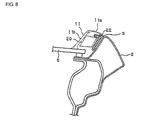
- FIG. 8 is a sectional view taken along line b-b of FIG. 7 .
- the bag inflation direction limiting member 22 includes a fixing portion 22A that has a substantially L-shaped cross sectional shape and that is a plate-like member and a hiding portion 22B that hides the gap between the fender 3 and the windshield 6.
- the fixing portion 22A has a vehicle body fixing portion 22a that is fixed to the vehicle 1, for example, with a screw, a bag fixing portion 22b that fixes the airbag 20, a side wall guide portion 22c that upstands substantially perpendicularly to the windshield 6, and an extension portion 22d that extends from one end of the side wall guide portion 22c substantially parallel to the upper cover 11a.
- the side wall guide portion 22c is provided with a hook portion 22e to be hooked to an engaging hole 2a provided in the front pillar 2 shown in FIG. 6 .
- the hiding portion 22B has a joining portion 22f that has a smooth curved surface along the front pillar 2 and that is joined to the fixing portion 22A, and a curved portion 22g that is provided at the end opposite from the fixing portion 22A and through which the pipe 16 is passed.
- FIGS. 7 and 8 show a state where the bag inflation direction limiting member 22 is attached to the vehicle 1.
- the hook portion 22e shown in FIG. 5 is hooked to the engaging hole 2a of the front pillar 2 shown in FIG. 6 , and the vehicle body fixing portion 22a is fixed to the vehicle 1, for example, with a screw.
- the fixing portion 22A is securely attached so as to fit in the front pillar 2.
- the hiding portion 22B hides the gap between the fender 3 and the windshield 6 so that the airbag 20 can be prevented from getting under the fender 3, and guides the pipe 16 with the curved portion 22g.
- FIG. 9 shows the operation of the airbag apparatus 10 of this embodiment.
- FIG. 10 is a sectional view of the airbag apparatus 10 in operation.
- the airbag apparatus 10 in its housed state shown in FIG. 3 is activated when the vehicle 1 collides with an object (not shown) and a detecting means (not shown) detects the impact force applied to the vehicle 1, on the basis of the detection signal, for example, by a control means.
- FIG. 9 (a) shows an early stage of inflation in which the airbag apparatus 10 starts operation, gas flows from the gas generator 15 housed in the fender 3 through the pipe 16 into the airbag 20, and the airbag 20 starts to inflate.
- the fender 3 side of the airbag 20 inflates first, and the cover 11 shown in FIGS. 3 and 4 opens due to the inflation pressure.
- the inflation direction of the airbag 20 is limited by the side wall guide portion 22c and the extension portion 22d of the bag inflation direction limiting member 22, to the direction toward the center of the vehicle.
- the gap S between the cover 11 and the front pillar 2 is hidden, and the airbag 20 does not protrude from the gap S. Therefore, the airbag apparatus 10 can stably operate.
- FIG. 9 (b) shows a middle stage of inflation in which gas flows from the gas generator 15 through the pipe 16 into the airbag 20, and the airbag 20 continues to inflate.
- the entire airbag 20 is completely exposed outside from its folded state. At this time, no tension is applied to the developing position limiting means 21, and the inflation of the airbag 20 is continued.
- FIG. 9 (c) shows a completion stage of inflation in which the inflation of the airbag 20 is completed. In the completion stage of inflation, the airbag 20 is completely inflated. The state of the airbag apparatus 10 in the completion stage of inflation will be described.
- FIG. 11 is a perspective view of the front pillar 2 and its vicinity in the completion stage of inflation.
- FIG. 12 is a sectional view taken along line c-c of FIG. 11 .
- FIG. 13 is a sectional view taken along line d-d of FIG. 11 .
- FIG. 14 is an enlarged view of the through anchor 14 and its vicinity.
- the airbag 20 develops above parts of the fender 3 and the hood 4 and in front of the front pillar 2, in the direction along the front pillar 2.
- the other end 21b of the developing position limiting means 21 engaged with the airbag 20 is pulled in response to the inflation of the airbag 20, as shown by arrow A, away from the roof 5. Therefore, relative to the through anchor 14, the middle portion 21c of the developing position limiting means 21 is pulled, as shown by arrow B, toward the roof 5, and is pressed against the windshield 6 and the front pillar 2. As shown in FIG. 12 , the airbag 20 through which the developing position limiting means 21 is passed is also pressed against the windshield 6 and the front pillar 2.
- the form of the developing position limiting means 21 is not limited to this embodiment but any other form can be taken as long as it presses the airbag 20 against the windshield 6 and the front pillar 2 when the airbag 20 inflates.
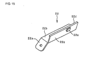
- FIG. 15 shows a second embodiment of a bag inflation direction limiting member 22.
- the bag inflation direction limiting member 22 is a fixing member that has a substantially L-shaped cross sectional shape, and has a vehicle body fixing portion 22a that is fixed to the vehicle 1, for example, with a screw, a bag fixing portion 22b that fixes the airbag 20, a side wall guide portion 22c that upstands substantially perpendicularly to the windshield 6, and an extension portion 22d that extends from one end of the side wall guide portion 22c substantially parallel to the upper cover 11a.
- the side wall guide portion 22c is provided with a hook portion 22e to be hooked to the engaging hole 2a provided in the front pillar 2 shown in FIG. 6 .
- FIG. 16 shows a third embodiment of a bag inflation direction limiting member 22.
- cutouts 22h are provided at the border between the side wall guide portion 22c and the extension portion 22d of the bag inflation direction limiting member 22 so that the extension portion 22d can easily bend relative to the side wall guide portion 22c as shown in FIG. 16 (b) .
- This structure can be applied to the bag inflation direction limiting members 22 of the first and second embodiments and bag inflation direction limiting members 22 having other structures.
- the inflation direction of the airbag 20 is limited to the direction toward the center of the vehicle, the airbag 20 does not protrude from the gap between the cover 11 and the front pillar 2, and therefore the airbag apparatus 10 can stably operate; and in the completion stage of inflation, since the airbag 20 develops in front of the front pillar 2 and in the direction along the front pillar 2, the airbag 20 can develop over a wide range.
- the gas generator 15 is housed in the fender 3
- the gas generator 15 may be housed in the roof 5. In this case, it is preferable to dispose the anchor 13 in the roof 5 and the through anchor 14 in the fender 3.
- the airbag apparatus 10 includes the bag inflation direction limiting member 22 disposed so as to hide the gap between the cover 11 and the front pillar 2. Therefore, when the airbag 20 inflates, the airbag 20 can be prevented from getting into the gap between the front pillar 2 and the cover 11 and protruding therefrom. Therefore, the airbag 20 can smoothly inflate and develop.
- the pipe 16 has a pipe outlet 16a that discharges gas in the airbag 20, and the bag inflation direction limiting member 22 is disposed at least near the pipe outlet 16a on the windshield 6 side of the front pillar 2. Therefore, when the airbag 20 starts to inflate, the airbag 20 can be prevented from getting into the gap between the front pillar 2 and the cover 11 and protruding therefrom. Therefore, the airbag 20 can smoothly inflate and develop.
- the bag inflation direction limiting member 22 has a hiding portion 22B that hides the gap between a fender 3 and a windshield 6 of a vehicle body, the airbag 20 can be prevented from getting under the fender 3.
- the bag inflation direction limiting member 22 has a bag fixing portion 22b that fixes the airbag 20, a side wall guide portion 22c that upstands relative to the windshield 6, and an extension portion 22d that extends from one end of the side wall guide portion 22c substantially parallel to the cover. Therefore, the airbag 20 can be stably held and can be stably inflated and developed.
- a cutout 22h is provided at the junction between the side wall guide portion 22c and the extension portion 22d. Therefore, when the airbag 20 inflates, the extension portion 22d can be easily deformed. Therefore, the airbag 20 can inflate over a wide range in the width direction.
- an airbag apparatus includes an airbag, an inflator that discharges gas into the airbag, a pipe that connects the airbag and the inflator, a detecting means that detects a collision, a control means that activates the inflator in response to a signal from the detecting means, and a cover that houses the airbag.
- the airbag disposed along a front pillar is inflated outside a vehicle.
- the airbag apparatus includes a bag inflation direction limiting member disposed so as to hide the gap between the cover and the front pillar. Therefore, when the airbag inflates, the airbag can be prevented from getting into the gap between the front pillar and the cover and protruding therefrom. Therefore, the airbag can smoothly inflate and develop.
- the pipe has a pipe outlet that discharges gas in the airbag
- the bag inflation direction limiting member is disposed at least near the pipe outlet on the windshield side of the front pillar. Therefore, when the airbag starts to inflate, the airbag can be prevented from getting into the gap between the front pillar and the cover and protruding therefrom. Therefore, the airbag can smoothly inflate and develop.
- the bag inflation direction limiting member has a hiding portion that hides the gap between a fender and a windshield of a vehicle body, the airbag can be prevented from getting under the fender.
- the bag inflation direction limiting member has a bag fixing portion that fixes the airbag, a side wall guide portion that upstands relative to the windshield, and an extension portion that extends from one end of the side wall guide portion substantially parallel to the cover. Therefore, the airbag can be stably held and can be stably inflated and developed.
- a cutout is provided at the junction between the side wall guide portion and the extension portion. Therefore, when the airbag inflates, the extension portion can be easily deformed. Therefore, the airbag can inflate over a wide range in the width direction.
Claims (5)
- Dispositif d'airbag comprenant :un airbag (20) ;un générateur de gaz (15) soufflant un gaz à l'intérieur de l'airbag ; un conduit (16) reliant l'airbag au générateur de gaz ;un moyen de détection pour la détection d'un choc ;un moyen de commande activant le générateur de gaz en réponse à un signal du moyen de détection ; etun couvercle (11) recouvrant l'airbag,où l'airbag est prévu pour être disposé le long d'un montant avant (2), de manière à être gonflé à l'extérieur d'un véhicule, caractérisé en ce quele dispositif d'airbag comprend un élément limiteur de direction de gonflement de coussin (22) disposé de manière à cacher une lacune (5) entre le couvercle et le montant avant.
- Dispositif d'airbag selon la revendication 1, où le conduit a une sortie de conduit (16a) refoulant du gaz dans l'airbag, et où l'élément limiteur de direction de gonflement de coussin est disposé au moins à proximité de la sortie de conduit sur le côté pare-brise (6) du montant avant.
- Dispositif d'airbag selon la revendication 1 ou la revendication 2, où l'élément limiteur de direction de gonflement de coussin a une partie de cache (22B) qui cache la lacune entre une aile (3) et un pare-brise (6) d'une caisse de véhicule.
- Dispositif d'airbag selon l'une des revendications 1 à 3, où l'élément limiteur de direction de gonflement de coussin a une partie de fixation de coussin (22b) qui fixe l'airbag, une partie de guidage de paroi latérale (22c) en saillie par rapport au pare-brise, et une partie d'extension (22d) qui s'étend d'une extrémité de la partie de guidage de paroi latérale, sensiblement parallèlement au couvercle.
- Dispositif d'airbag selon la revendication 4, où une découpe (22h) est prévue à la jonction entre la partie de guidage de paroi latérale et la partie d'extension.
Applications Claiming Priority (1)
| Application Number | Priority Date | Filing Date | Title |
|---|---|---|---|
| JP2007268685A JP2009096278A (ja) | 2007-10-16 | 2007-10-16 | エアバッグ装置 |
Publications (3)
| Publication Number | Publication Date |
|---|---|
| EP2050632A2 EP2050632A2 (fr) | 2009-04-22 |
| EP2050632A3 EP2050632A3 (fr) | 2009-06-24 |
| EP2050632B1 true EP2050632B1 (fr) | 2010-11-24 |
Family
ID=40139261
Family Applications (1)
| Application Number | Title | Priority Date | Filing Date |
|---|---|---|---|
| EP08163019A Expired - Fee Related EP2050632B1 (fr) | 2007-10-16 | 2008-08-27 | Dispositif d'airbag |
Country Status (3)
| Country | Link |
|---|---|
| EP (1) | EP2050632B1 (fr) |
| JP (1) | JP2009096278A (fr) |
| DE (1) | DE602008003640D1 (fr) |
Families Citing this family (5)
| Publication number | Priority date | Publication date | Assignee | Title |
|---|---|---|---|---|
| JP5000542B2 (ja) * | 2008-02-06 | 2012-08-15 | タカタ株式会社 | エアバッグ装置 |
| JP4972024B2 (ja) * | 2008-03-27 | 2012-07-11 | タカタ株式会社 | エアバッグ装置 |
| EP2586665B1 (fr) * | 2010-06-23 | 2015-08-12 | Honda Motor Co., Ltd. | Dispositif de coussin de sécurité gonflable |
| EP2565087B1 (fr) * | 2010-06-23 | 2015-07-29 | Honda Motor Co., Ltd. | Dispositif de coussin de sécurité gonflable |
| US11529927B2 (en) * | 2018-12-11 | 2022-12-20 | Hyundai Motor Company | Airbag apparatus for vehicle |
Family Cites Families (4)
| Publication number | Priority date | Publication date | Assignee | Title |
|---|---|---|---|---|
| JP2002283939A (ja) | 2001-03-29 | 2002-10-03 | Toyota Motor Corp | 歩行者保護エアバッグ装置 |
| JP3682502B2 (ja) | 2002-04-12 | 2005-08-10 | 本田技研工業株式会社 | 車両外置きエアバッグ装置 |
| JP2005096686A (ja) * | 2003-09-26 | 2005-04-14 | Toyota Motor Corp | ピラーエアバッグ装置 |
| JP4175338B2 (ja) * | 2005-04-20 | 2008-11-05 | トヨタ自動車株式会社 | エアバッグ装置 |
-
2007
- 2007-10-16 JP JP2007268685A patent/JP2009096278A/ja active Pending
-
2008
- 2008-08-27 DE DE602008003640T patent/DE602008003640D1/de active Active
- 2008-08-27 EP EP08163019A patent/EP2050632B1/fr not_active Expired - Fee Related
Also Published As
| Publication number | Publication date |
|---|---|
| EP2050632A2 (fr) | 2009-04-22 |
| JP2009096278A (ja) | 2009-05-07 |
| EP2050632A3 (fr) | 2009-06-24 |
| DE602008003640D1 (de) | 2011-01-05 |
Similar Documents
| Publication | Publication Date | Title |
|---|---|---|
| US7011337B2 (en) | Occupant restraint system | |
| US7607685B2 (en) | Automobile side airbag guide plate | |
| US7121579B2 (en) | Occupant restraint system | |
| JP3592654B2 (ja) | 乗員拘束装置 | |
| US7874579B2 (en) | Curtain airbag bracket and curtain airbag device | |
| JP2009143379A (ja) | サイドエアバッグ装置 | |
| MX2011008189A (es) | Dispositivo de bolsa de aire proteccion de cabeza para vehiculos. | |
| JP2002362292A (ja) | 乗員拘束装置 | |
| EP2050633A2 (fr) | Dispositif d'airbag | |
| EP2050632B1 (fr) | Dispositif d'airbag | |
| JP3592653B2 (ja) | 乗員拘束装置 | |
| JP2005104234A (ja) | エアバッグ装置 | |
| EP2050635B1 (fr) | Dispositif d'airbag | |
| JP2008114739A (ja) | カーテンエアバッグ装置を備えた車両の後部構造 | |
| JP2002362287A (ja) | 乗員拘束装置 | |
| JP2002362286A (ja) | 乗員拘束装置 | |
| JP5318616B2 (ja) | カーテンエアバッグ装置 | |
| EP2112033B1 (fr) | Dispositif de coussin d'air de type rideau | |
| EP2050634B1 (fr) | Dispositif d'airbag | |
| JP3631980B2 (ja) | 乗員拘束装置 | |
| JP3626700B2 (ja) | 乗員拘束装置 | |
| JP3200589B2 (ja) | 頭部保護エアバッグ袋体を格納したフロントピラーガーニッシュの配設構造 | |
| JP5145173B2 (ja) | エアバッグ装置 | |
| JP2007038957A (ja) | エアバッグ装置 | |
| KR101021002B1 (ko) | 커튼형 에어백 장치 |
Legal Events
| Date | Code | Title | Description |
|---|---|---|---|
| PUAI | Public reference made under article 153(3) epc to a published international application that has entered the european phase |
Free format text: ORIGINAL CODE: 0009012 |
|
| AK | Designated contracting states |
Kind code of ref document: A2 Designated state(s): AT BE BG CH CY CZ DE DK EE ES FI FR GB GR HR HU IE IS IT LI LT LU LV MC MT NL NO PL PT RO SE SI SK TR |
|
| AX | Request for extension of the european patent |
Extension state: AL BA MK RS |
|
| PUAL | Search report despatched |
Free format text: ORIGINAL CODE: 0009013 |
|
| AK | Designated contracting states |
Kind code of ref document: A3 Designated state(s): AT BE BG CH CY CZ DE DK EE ES FI FR GB GR HR HU IE IS IT LI LT LU LV MC MT NL NO PL PT RO SE SI SK TR |
|
| AX | Request for extension of the european patent |
Extension state: AL BA MK RS |
|
| 17P | Request for examination filed |
Effective date: 20091202 |
|
| 17Q | First examination report despatched |
Effective date: 20100125 |
|
| AKX | Designation fees paid |
Designated state(s): DE GB |
|
| GRAP | Despatch of communication of intention to grant a patent |
Free format text: ORIGINAL CODE: EPIDOSNIGR1 |
|
| GRAS | Grant fee paid |
Free format text: ORIGINAL CODE: EPIDOSNIGR3 |
|
| GRAA | (expected) grant |
Free format text: ORIGINAL CODE: 0009210 |
|
| AK | Designated contracting states |
Kind code of ref document: B1 Designated state(s): DE GB |
|
| REG | Reference to a national code |
Ref country code: GB Ref legal event code: FG4D |
|
| REF | Corresponds to: |
Ref document number: 602008003640 Country of ref document: DE Date of ref document: 20110105 Kind code of ref document: P |
|
| PLBE | No opposition filed within time limit |
Free format text: ORIGINAL CODE: 0009261 |
|
| STAA | Information on the status of an ep patent application or granted ep patent |
Free format text: STATUS: NO OPPOSITION FILED WITHIN TIME LIMIT |
|
| 26N | No opposition filed |
Effective date: 20110825 |
|
| REG | Reference to a national code |
Ref country code: DE Ref legal event code: R097 Ref document number: 602008003640 Country of ref document: DE Effective date: 20110825 |
|
| PGFP | Annual fee paid to national office [announced via postgrant information from national office to epo] |
Ref country code: DE Payment date: 20130821 Year of fee payment: 6 |
|
| PGFP | Annual fee paid to national office [announced via postgrant information from national office to epo] |
Ref country code: GB Payment date: 20130821 Year of fee payment: 6 |
|
| REG | Reference to a national code |
Ref country code: DE Ref legal event code: R119 Ref document number: 602008003640 Country of ref document: DE |
|
| GBPC | Gb: european patent ceased through non-payment of renewal fee |
Effective date: 20140827 |
|
| REG | Reference to a national code |
Ref country code: DE Ref legal event code: R119 Ref document number: 602008003640 Country of ref document: DE Effective date: 20150303 |
|
| PG25 | Lapsed in a contracting state [announced via postgrant information from national office to epo] |
Ref country code: GB Free format text: LAPSE BECAUSE OF NON-PAYMENT OF DUE FEES Effective date: 20140827 Ref country code: DE Free format text: LAPSE BECAUSE OF NON-PAYMENT OF DUE FEES Effective date: 20150303 |