EP2050605A2 - Schiebedachstruktur und Fahrzeug, das mit dieser Struktur ausgerüstet ist - Google Patents
Schiebedachstruktur und Fahrzeug, das mit dieser Struktur ausgerüstet ist Download PDFInfo
- Publication number
- EP2050605A2 EP2050605A2 EP08164117A EP08164117A EP2050605A2 EP 2050605 A2 EP2050605 A2 EP 2050605A2 EP 08164117 A EP08164117 A EP 08164117A EP 08164117 A EP08164117 A EP 08164117A EP 2050605 A2 EP2050605 A2 EP 2050605A2
- Authority
- EP
- European Patent Office
- Prior art keywords
- cover
- vehicle
- cover member
- roof
- rails
- Prior art date
- Legal status (The legal status is an assumption and is not a legal conclusion. Google has not performed a legal analysis and makes no representation as to the accuracy of the status listed.)
- Withdrawn
Links
Images


Classifications
-
- B—PERFORMING OPERATIONS; TRANSPORTING
- B60—VEHICLES IN GENERAL
- B60J—WINDOWS, WINDSCREENS, NON-FIXED ROOFS, DOORS, OR SIMILAR DEVICES FOR VEHICLES; REMOVABLE EXTERNAL PROTECTIVE COVERINGS SPECIALLY ADAPTED FOR VEHICLES
- B60J7/00—Non-fixed roofs; Roofs with movable panels, e.g. rotary sunroofs
- B60J7/02—Non-fixed roofs; Roofs with movable panels, e.g. rotary sunroofs of sliding type, e.g. comprising guide shoes
- B60J7/06—Non-fixed roofs; Roofs with movable panels, e.g. rotary sunroofs of sliding type, e.g. comprising guide shoes with non-rigid element or elements
- B60J7/061—Non-fixed roofs; Roofs with movable panels, e.g. rotary sunroofs of sliding type, e.g. comprising guide shoes with non-rigid element or elements sliding and folding
-
- B—PERFORMING OPERATIONS; TRANSPORTING
- B60—VEHICLES IN GENERAL
- B60J—WINDOWS, WINDSCREENS, NON-FIXED ROOFS, DOORS, OR SIMILAR DEVICES FOR VEHICLES; REMOVABLE EXTERNAL PROTECTIVE COVERINGS SPECIALLY ADAPTED FOR VEHICLES
- B60J7/00—Non-fixed roofs; Roofs with movable panels, e.g. rotary sunroofs
- B60J7/02—Non-fixed roofs; Roofs with movable panels, e.g. rotary sunroofs of sliding type, e.g. comprising guide shoes
- B60J7/06—Non-fixed roofs; Roofs with movable panels, e.g. rotary sunroofs of sliding type, e.g. comprising guide shoes with non-rigid element or elements
- B60J7/067—Non-fixed roofs; Roofs with movable panels, e.g. rotary sunroofs of sliding type, e.g. comprising guide shoes with non-rigid element or elements sliding and winding up
-
- B—PERFORMING OPERATIONS; TRANSPORTING
- B60—VEHICLES IN GENERAL
- B60J—WINDOWS, WINDSCREENS, NON-FIXED ROOFS, DOORS, OR SIMILAR DEVICES FOR VEHICLES; REMOVABLE EXTERNAL PROTECTIVE COVERINGS SPECIALLY ADAPTED FOR VEHICLES
- B60J7/00—Non-fixed roofs; Roofs with movable panels, e.g. rotary sunroofs
- B60J7/20—Vehicle storage compartments for roof parts or for collapsible flexible tops
Definitions
- the present invention relates to a sliding roof structure for covering the opening in a roof of a vehicle with a cover.
- vehicle roof structures such as sunroof, open roof and sliding roof are well known.
- the sliding roof structure also known as canvas top structure or open roof structure, which hereinafter called sliding roof structure in this specification, allows the roof to be opened more widely, thus providing passengers enhanced sense of openness.
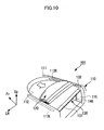
- a part of the roof 210 of a sliding roof type vehicle 200 is cut off to form an opening 211, to which a cover member 220 is attached in openable/closable state.
- a cover member 220 is attached in openable/closable state.
- a conventional sliding roof type vehicle is disclosed in JP2003-507244A ( Figures 1 and 2 )
- the opening 211 In order to provide passengers on a sliding roof type vehicle 200 with enhanced sense of openness, the opening 211 must be made as large as possible. However, with the conventional sliding roof type vehicles, the opening 211 cannot be made larger exceeding the limitations imposed by their manufacturing procedures, where the roof of the vehicle is replaced by a sliding roof. In addition, as shown in Figure 19 , the folded cover member 220 occupies some part of the opening 211, hampering the opening from being made larger.
- the purpose of the present invention is to provide an opening larger than that of conventional sliding roof type vehicles by transferring folded cover into the vehicle.
- a sliding roof structure for opening/closing an opening in the roof of a vehicle with a cover member comprising; a cover storage means which constitutes the rear end of the roof and stores the cover member, and a guiding means for transferring the cover storage means between a position at the rear end of the roof and a position inside the vehicle.
- the cover storage means includes a winding means for winding the cover member.
- the guiding means is equipped with lifting/lowering rails installed between the position at the rear end of the roof and the position inside the vehicle.
- the sliding roof structure has a stopper mechanism for maintaining the cover storage means at the rear end of the roof. Also the lifting/lowering rails are installed inclined so that the position inside the vehicle is nearer to the front than the position at the rear end of the vehicle.
- a sliding roof structure for opening/closing an opening in the roof of a vehicle with a cover comprising; opening/closing rails installed along the opening for guiding the transfer of the cover member, a cover member tray for holding the folded cover member, and r lifting/lowering rails for guiding the cover member tray from the roof position to the position inside the vehicle, which is under the roof position.
- a sliding roof structure of a vehicle comprising: an opening formed in the roof, a foldable cover member for covering the opening, opening/closing rails installed along the edge portion on the right and left sides of the opening to guide the cover member so that the cover member slides in the longitudinal direction of the vehicle, a cover member tray for holding the folded cover member, lifting/lowering rails for guiding the cover member tray so that the cover member tray moves between the first position at the rear side of the opening/closing rails and the second position under the first position, and retaining means for retaining the cover member tray at the first position in releasable state, wherein the cover member is slid and folded toward the rear side of the roof to form the opening, the entire cover member is placed on the cover, and the cover member tray is lowered from the first position to the second position inside the vehicle.
- the cover member tray includes a convex protruding outward in the width direction of the vehicle at the edge portion on right and left sides of the tray, the lifting/lowering rails include a guide groove along which the convex slides, the retaining means includes a protruding piece that protrudes into or retracted from the guide groove, and the convex is placed on the protruding piece to retain the cover member tray at the first position.
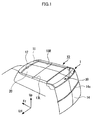
- Figure 1 shows a perspective view of a hatchback type vehicle (10) featuring a sliding roof structure of the first embodiment of this invention.
- This vehicle 10 has an opening 12 in its roof 11.
- the opening 12 has been formed by cutting the area from the rear to the front of the roof in an arch-like shape, with the edges on both sides left as they are.
- This opening 12 can be covered with a cover 20, or left open.
- the first rails 13L and 13R for transferring the cover 20 are installed along the right and left edges of the opening 12, which extend in the longitudinal direction of the vehicle.
- the roof 11 of the vehicle 10 of the first embodiment of this invention has been cut in a gate-like shape, and as shown in Figure 2 , there is nothing between the right and left rear corners 14L, 14R of the roof.
- a cover storage member 30 is provided between both corners 14L, 14R. This cover storage member 30 constitutes the rear edge of the roof 11.
- the rear door and rear window glass are not shown.
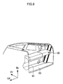
- Figure 3 is a perspective view of the cover storage member 30 provided with a space for storing the cover.
- a shaft 31, to which one end of the cover 20 is fastened, and a motor 33 for rotating the shaft 31 via a belt 32 are provided within the storage space.
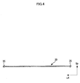
- Figure 4 is a cross-sectional view viewed from A-A in Figure 3 .
- a wire 35 is attached to the both ends of the cover 20, and one end of the wire 35 is fastened to the shaft 31.
- the wire 35 is sent from the entrance 34 of the cover storage member 30 toward the front of the roof along the first rails 13L, 13R by normal rotation of the motor 33.
- the cover stretches over the roof 11, following the movement of the wire 35, thus covering the opening 12.
- reverse rotation of the motor 33 winds up the cover 20 stretched over the roof 11 along with the wire 35, thus forming the opening 12.
- the edge of the insertion slot 13G at the rear end of the first rail 13R is chamfered so that the cover 20 sent from the entrance 34 of the cover storage member 30 enters the first rails 13L, 13R smoothly.
- the sliding roof structure of the first embodiment of this invention is designed to allow the cover storage member 30 to move from the position at the rear edge of the roof, hereafter referred to as position A, to the position on the deck shown by dotted line at the back of the rear seat 15, hereafter referred to as position B.
- the sliding roof structure 1 of this invention is equipped with a guiding means 40 for transferring the cover storage member 30 between position A and position B, as shown in Figure 6 .
- this guiding means 40 is equipped with second rails 41, which are installed between position A and position B to move the cover storage member 30 up and down, and a transferring means 42 for moving the cover storage member 30.
- the second rails 41 installed on the inner walls 19 (see figure 2 ) at the rear of the vehicle extend in the vertical direction.
- two rails 41 are laid apart from each other in the longitudinal direction of the vehicle on the right and left sides of the vehicle.
- a convex protruding outward in the width direction of the vehicle is provided on the right and left edges of the cover storage member 30 as shown in Figure 7 .
- two convexes 36, 36 are provided apart from each other in the longitudinal direction of the vehicle. These convexes 36 are slid along and supported by the second rails 41, which allows the cover storage member 30 to move up and down.
- the cover storage member 30 moves up and down along the second rails 41 via the transferring means 42.
- the transferring means 42 is comprised of a motor 42A, pulley 42B mounted to the rotating shaft of the motor 42A, wire 42C sent from the pulley 42 via normal rotation of the motor 42A and rewound around the pulley 42B via reverse rotation of the motor 42A, and tube 42D for guiding the wire 42C.
- the edges of the tube 42D are attached to the lower part of the second rails 41, and the wire 42C coming out of the tube 42D passes within the second rails 41 and connected to the convex 36 provided at the edges of the cover storage member 30, which slides along the second rails 41, from the bottom.
- the first embodiment of this invention is equipped with a stopper mechanism 50, which prevents the cover storage member 30 from going down when it is at position A.
- a stopper mechanism 50 which prevents the cover storage member 30 from going down when it is at position A.
- locking members 51 for locking the convexes 36 at the top of the second rails 41 are installed at the top of the second rails 41, in a state in which the locking members 51 are protruded into or retracted from the second rails 41, and normally kept protruded with the repulsive force of springs 52.
- the deck 60 is provided with a concave 61 for partially embedding the cover storage member 30.
- the sliding roof structure 1 of the first embodiment of this invention is described below.
- the front part of the cover 20 is slid toward the back of the vehicle as in the case of conventional sliding roof type vehicles.
- reverse rotation of the motor 33 installed within the cover storage member 30 winds the cover 20 up around the shaft 31, and thus the cover 20 is stored in the cover storage member 30.
- the position of the cover storage member 30 is controlled by the stopper mechanism 50 so that it is maintained at position A. If a user operates the in-vehicle switch to drive the transferring means 42, the motor 42A is actuated to wind up the wire 42C around the pulley 42B, thus applying force for transporting the cover storage member 30 downward.
- the cover 20 wound up as a result of forming the opening 12 in the roof 11 can be transferred from the position on the roof 11 to inside the vehicle. Consequently, since the cover does not occupy a part of the roof 11, unlike conventional sliding roof structures, the opening 12 can be made larger. Meanwhile, since the cover 20 is wound up within the cover storage member 30, it is not visible through the rear window glass 14a even if it is transferred to inside the vehicle. In addition, in the first embodiment of this invention, since the top edge of the rear window glass 14a is configured to directly contact the cover storage member 30 at position A, a larger opening is formed by lowering the cover storage member 30 together with the rear window glass 14a.
- FIG. 10 shows a perspective view of a hatchback type vehicle 110 featuring a sliding roof structure 101 of the second embodiment of this invention.
- the vehicle 110 has an opening 112 in its roof 111.
- the opening 112 has been formed by cutting the area from the rear to the front of the roof in an arch-like shape, with the edges on both sides left as they are. This opening 112 can be covered by a cover 120, or left open.
- the cover 120 is equipped with multiple rods (not shown), which extend outward in the width direction, placed at specified intervals in the longitudinal direction of the vehicle.
- the tip of each rod protrudes from the right or left edge of the cover 120 outwards in the width direction of the vehicle.
- the first rails 113L and 113R for guiding the tip of these rods are provided along the right and left edges, which extend in the longitudinal direction of the vehicle, of the opening 112 respectively.
- the cover 120 is supported by and slides along the first rails 113L and 113R.
- the cover 120 is folded through a process in which the cloth between rods adjacent to each other is folded when the front and the rear edges of the cover 120 are moved closer to each other. By folding the cover 120 while moving it toward the rear side of the vehicle, an opening 112 is formed.
- the sliding roof structure 101 in the second embodiment of this invention is configured to allow the cover 120 to move from the roof surface to inside the vehicle.
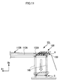
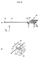
- the sliding roof structure 101 of this invention is equipped with a tray for the cover 130, second rails 140, and a retaining means 150 (see Figure 13 ).
- the tray for the cover 130 is used for placing the cover on it in folded state for transportation. As shown in Figure 11 , the tray for the cover 130 moves between position A, the rear end of the first rail 113R laid in horizontal direction, and position B, the second position that is lower than position A.
- the tray for the cover 130 is provided with a base plate 131, whose long sides extend in the width direction of the vehicle, and extension rails 132, 132 installed at the right and left sides of the base plate 131.
- the dimensions of the base plate 131 are determined so that it extends horizontally under the entire area of folded cover.
- the extension rails 132, 132 are used for guiding the tips of the rods, which protrude from the right and left edges of the cover 120, respectively.
- the extension rails 132, 132 are placed behind the first rails 113L, 113R at the same height as the first rails (113L, 113R).
- extension guide grooves 132A which are connected to the guide grooves 113A of the first rails 113L, 113R in a state in which the tray for the cover 130 is retained at the first position (A), are formed on the extension rails 132, 132, as shown in Figure 11 .
- each rod is transferred along these guide grooves 113A, 132A.
- the rod mounted to the back end of the cover 120 is fastened to the tray for the cover 130.
- the extension guide groove 132A of the extension rail 132 extends to the middle of the extension rail 132 slightly to the rear of the vehicle, and the rod mounted to the rear end of the cover 120 are fastened at the position of the rear end of this extension guide groove 132A.
- a convex protruding outward in the width direction of the vehicle is provided at the right and left sides of the tray for the cover 130.
- the convex 133 is mounted to the base plate 131 via a bracket 134.
- two convexes 133, 133 are provided apart from each other in the longitudinal direction of the vehicle.
- the second rails 140 installed on the inner wall 115 at the rear of the vehicle extend in the vertical direction.
- two rails 140, 140 each are laid apart from each other in the longitudinal direction of the vehicle on the right and left sides of the vehicle.
- a guide groove 141 for guiding the convex is formed along the longitudinal direction of the second rails 140, 140.
- the dimensions of the second rails 140, 140 are determined, and the second rails 140, 140 are mounted to a desired position on the internal wall 115, so that the tray for the cover 130 can be transferred vertically, guided by the second rails 140, from the first position (A), which is on the surface of the roof, to the second position (B), the position within the vehicle directly below the first position (A).
- a retaining means 150 is used for retaining the tray for the cover 130 at the top of the second rails 140, in a state where the cover can be released.
- the tray for the cover 130 is retained at the first position (A) with the retaining means 150.
- the retaining means 150 is equipped with a protruding piece 151, which can be protruded into or retracted from the guide groove 141 of the second rail 140.
- the protruding piece 151 is comprised of a base 151A and a rotating part 151C, which is mounted to the base 151A in rotatable state via a hinge 151B.
- the base 151A moves within a cylindrical part 143, which is integrated in the side wall 142 of the guide groove 141. Furthermore, as shown in Figure 15 , the base 151A is forced to move toward the guide groove 141 with a spring 145.
- the cylindrical part 143 is formed with its shaft extended in the direction orthogonal to the longitudinal direction of the guide groove 141.
- the base 151A moves within the cylindrical part 143 to make the rotating part 151C, which is installed at the edge of the base 151A, protrude into or retract from the guide groove 141.
- the length (L) of the rotating part 151C is made longer than the width (W) of the guide groove 141 (see Figure 14 ), and consequently, when the rotating part 151C is protruded into the guide groove 141, its connecting part with the base 151A is placed on the guiding surface 143A of the cylindrical part 143. Furthermore, a concave 141B for housing the rotating part 151C is provided on the surface 141A of the guide groove 141 above the guiding surface 143A The rotating part 151C of the protruding piece 151 is rotated upward and then housed in the concave 141B. The depth and shape of the concave 141B is determined so that the rotating part 151C is housed flash with the surface of the guide groove 141.
- a wire 155 is connected to the protruding piece 151, and the other end of the wire is connected to a switching device (not shown) installed within the vehicle via a pulley 156.
- the switching device integrates a motor, for example, and the motor winds up the wire 155 to retract the protruding piece 151 of the retaining means 150 from the guide groove 141.
- This structure allows the convex 133 placed on the upper surface of the protruding piece 151 to move downward when the protruding piece 151 is retracted from the guide groove 141, and thus the tray for the cover 130 can move downward.
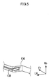
- the tray for the cover 130 is moved up or down along the second rails 140 with a lifting and lowering device160 shown in Figure 16 .
- the lifting and lowering device 160 is equipped with a motor 161 and two pairs of wires 162 connected to the motor 161.
- the end of a pair of wires 162, 162 is attached on the right and left sides of the tray for the cover 130 at positions away from each other in the longitudinal direction of the vehicle.
- the motor 161 controls the length of the wire 162, thus lifting or lowering the tray for the cover 130.
- the tray for the cover 130 is shown schematically in Figure 16 .
- the tray for the cover 130 can be lifted by winding up the wire 160B connected to the convex 133 with a motor 160A installed at the position adjacent to the surface of the roof at the rear part of the vehicle, as shown in Figure 17 .
- first hook members 121 are provided on both sides of the front edge of the cover 120, as shown in Figure 18 (A) , and the first hook members 121 are transferred toward the front or the rear side of the roof as a result of winding up or discharging of the wire 117 by the motor 116 integrated in the roof 111, and the opening 112 is thus closed or formed.
- the second hook member 118 mounted to the tip of the wire 117 is engaged in the first hook member 121.
- the first hook member 121 and the second hook member 118 are engaged in the longitudinal direction of the vehicle as shown by ⁇ in Figure 18 (B) .
- the shape and orientation of the hook constituting each hook member 118, 121 are determined so that the first hook member 121 is disengaged from the second hook member 118 when moved downward from the engaged position.
- the sliding roof structure 101 of the second embodiment of this invention is described below.
- the front part of the cover is slid toward the rear side of the vehicle as in the case of conventional sliding roof type vehicles ( Figure 10 ).
- the cloth between the front edge and the rear edge of the cover is folded and placed on the tray for the cover 130.
- the retaining means 150 maintains the tray for the cover 130 at the first position (A). If a user operates an in-vehicle switch to wind up the wire 155 connected to the protruding piece 151 of the retaining means 150, the protruding piece 151 is retracted from the guide groove 141. Consequently, the convex 133 moves downward, allowing the tray for the cover 130 to move from the first position (A) to the second position (B).
- the sliding roof structure 101 With the sliding roof structure 101 thus configured, by forming the opening 112 in the roof 111, the folded cover 120 can be moved from the position on the roof 111 to inside the vehicle. Since the cover 120 does not remain on the roof 111, unlike conventional sliding roof structures, a large opening 112 can be formed. Furthermore, since the top edge of the rear door glass directly contacts the tray for the cover 130, the opening can be made even larger if the rear door glass is lowered.
- the present invention allows the cover, which is folded to form an opening in the roof, to be transferred from the top (roof) to inside the vehicle. Consequently, the cover does not occupy roof area, unlike conventional sliding roof structures, allowing the opening to be made larger and thus providing passengers with enhanced sense of openness.
- Various embodiments are allowed without departing from the scope of the invention.
Applications Claiming Priority (2)
| Application Number | Priority Date | Filing Date | Title |
|---|---|---|---|
| JP2007268434A JP4534236B2 (ja) | 2007-10-15 | 2007-10-15 | キャンバストップ構造 |
| JP2007275815A JP4465688B2 (ja) | 2007-10-23 | 2007-10-23 | キャンバス格納構造 |
Publications (2)
| Publication Number | Publication Date |
|---|---|
| EP2050605A2 true EP2050605A2 (de) | 2009-04-22 |
| EP2050605A3 EP2050605A3 (de) | 2010-05-05 |
Family
ID=40130509
Family Applications (1)
| Application Number | Title | Priority Date | Filing Date |
|---|---|---|---|
| EP08164117A Withdrawn EP2050605A3 (de) | 2007-10-15 | 2008-09-11 | Schiebedachstruktur und Fahrzeug, das mit dieser Struktur ausgerüstet ist |
Country Status (2)
| Country | Link |
|---|---|
| US (1) | US7891729B2 (de) |
| EP (1) | EP2050605A3 (de) |
Cited By (1)
| Publication number | Priority date | Publication date | Assignee | Title |
|---|---|---|---|---|
| FR2950839A1 (fr) * | 2009-10-01 | 2011-04-08 | Webasto Systemes Carrosserie | Vehicule decouvrable a toit souple repliable |
Families Citing this family (4)
| Publication number | Priority date | Publication date | Assignee | Title |
|---|---|---|---|---|
| DE102014211163B4 (de) * | 2013-06-28 | 2023-12-21 | Bos Gmbh & Co. Kg | Schutzvorrichtung für einen Laderaum eines Kraftfahrzeugs sowie Antriebsvorrichtung hierfür |
| US9340143B2 (en) * | 2014-08-27 | 2016-05-17 | Ford Global Technologies, Llc | Adjustable cargo track system on side panel |
| DE102015220192B3 (de) * | 2015-10-16 | 2017-03-09 | Bos Gmbh & Co. Kg | Schutzvorrichtung für einen Laderaum eines Kraftfahrzeugs |
| USD847078S1 (en) * | 2017-07-06 | 2019-04-30 | Fca Us Llc | Automobile roof |
Citations (2)
| Publication number | Priority date | Publication date | Assignee | Title |
|---|---|---|---|---|
| JP2003507244A (ja) | 1999-08-24 | 2003-02-25 | プジョー シトロエン オートモビル エス アー | 自動車の居住空間の取外し可能な被覆用モジュール及びかかるモジュールを備えた自動車 |
| EP1747925A1 (de) | 2005-07-27 | 2007-01-31 | ArvinMeritor GmbH | Baugruppe aus einem Fahrzeug-Faltverdeck und einem Rollo |
Family Cites Families (13)
| Publication number | Priority date | Publication date | Assignee | Title |
|---|---|---|---|---|
| US2210590A (en) * | 1937-08-30 | 1940-08-06 | Jobst Conrad | Automobile |
| CH403509A (fr) * | 1963-11-18 | 1965-11-30 | Rollman Paul | Toit pour véhicule décapotable |
| JPH0722342Y2 (ja) | 1989-02-25 | 1995-05-24 | 池田物産株式会社 | 自動車のキャンバストップ構造 |
| JP3305784B2 (ja) | 1992-12-21 | 2002-07-24 | ベバスト ジャパン株式会社 | キャンバストップの開閉装置 |
| US5655807A (en) * | 1996-03-25 | 1997-08-12 | Rosario; Israel | Cover for the bed of a pickup truck with an associated roll-up housing |
| DE19927234C1 (de) | 1999-06-15 | 2000-07-27 | Webasto Vehicle Sys Int Gmbh | Führungsschiene |
| DE10032378C2 (de) | 2000-07-06 | 2002-10-24 | Webasto Vehicle Sys Int Gmbh | Umwandelbares Fahrzeugdach |
| DE60127572T2 (de) * | 2000-11-09 | 2007-12-27 | Inalfa Roof Systems Group B.V. | Schiebedachkonstruktion für ein fahrzeug sowie ein mit einer solchen schiebedachkonstruktion versehenes fahrzeug |
| DE10233029B4 (de) * | 2002-07-20 | 2005-01-05 | Webasto Vehicle Systems International Gmbh | Fahrzeug mit veränderbarem Heckaufbau |
| JP2003160063A (ja) | 2002-09-06 | 2003-06-03 | Hiroshi Yano | トランクが変形する乗用車 |
| FR2865163B1 (fr) * | 2004-01-21 | 2007-11-30 | France Design | Vehicule a toit decouvrable et hayon arriere |
| JP4413068B2 (ja) | 2004-04-28 | 2010-02-10 | ベバスト ジャパン株式会社 | 車両のルーフ格納構造 |
| FR2902045B1 (fr) * | 2006-06-12 | 2013-09-06 | Heuliez | Toit retractable inscrit dans une paroi superieure d'un vehicule |
-
2008
- 2008-09-11 EP EP08164117A patent/EP2050605A3/de not_active Withdrawn
- 2008-09-11 US US12/209,130 patent/US7891729B2/en not_active Expired - Fee Related
Patent Citations (2)
| Publication number | Priority date | Publication date | Assignee | Title |
|---|---|---|---|---|
| JP2003507244A (ja) | 1999-08-24 | 2003-02-25 | プジョー シトロエン オートモビル エス アー | 自動車の居住空間の取外し可能な被覆用モジュール及びかかるモジュールを備えた自動車 |
| EP1747925A1 (de) | 2005-07-27 | 2007-01-31 | ArvinMeritor GmbH | Baugruppe aus einem Fahrzeug-Faltverdeck und einem Rollo |
Cited By (1)
| Publication number | Priority date | Publication date | Assignee | Title |
|---|---|---|---|---|
| FR2950839A1 (fr) * | 2009-10-01 | 2011-04-08 | Webasto Systemes Carrosserie | Vehicule decouvrable a toit souple repliable |
Also Published As
| Publication number | Publication date |
|---|---|
| US20090224572A1 (en) | 2009-09-10 |
| EP2050605A3 (de) | 2010-05-05 |
| US7891729B2 (en) | 2011-02-22 |
Similar Documents
| Publication | Publication Date | Title |
|---|---|---|
| EP2050605A2 (de) | Schiebedachstruktur und Fahrzeug, das mit dieser Struktur ausgerüstet ist | |
| CN203318111U (zh) | 遮挡卷帘 | |
| CN103108761B (zh) | 遮阳板装置 | |
| JP6517646B2 (ja) | シェード装置 | |
| JP2008534358A (ja) | 自動車用積荷スペースカバー | |
| KR20110063373A (ko) | 차량 내부 공간용 보호 장치 | |
| KR101690823B1 (ko) | 차양장치 | |
| EP2050604A1 (de) | Aufbewahrungsstruktur zum Aufbewahren eines Abdeckungselements eines Fahrzeugs mit Schiebedach und Fahrzeug mit einem solchen Struktur | |
| JP2011046340A (ja) | サンシェード装置 | |
| US9586463B2 (en) | Top for an openable vehicle roof | |
| JP4534236B2 (ja) | キャンバストップ構造 | |
| JP7342327B2 (ja) | サンルーフ装置のデフレクタ機構 | |
| JP2010018233A (ja) | フロントドア開閉装置 | |
| JP2010069928A (ja) | 自動車の荷室用カバー装置 | |
| US8020915B2 (en) | Openable roof system for a motor car | |
| KR100868657B1 (ko) | 차량용 선바이저 장치 | |
| JP4397231B2 (ja) | サンルーフ装置 | |
| KR100747030B1 (ko) | 차량용 선루프 개폐장치 | |
| JP4352431B2 (ja) | キャンバス格納構造 | |
| JP2005186810A (ja) | 車両用リアゲート装置 | |
| JP3120245B2 (ja) | サンルーフ装置 | |
| JP3100306B2 (ja) | サンルーフのシェード装置 | |
| KR100916207B1 (ko) | 카고 스크린 | |
| JP2008260353A (ja) | 自動車ドア | |
| JPH02212220A (ja) | 電動スライド式サンバイザ |
Legal Events
| Date | Code | Title | Description |
|---|---|---|---|
| PUAI | Public reference made under article 153(3) epc to a published international application that has entered the european phase |
Free format text: ORIGINAL CODE: 0009012 |
|
| AK | Designated contracting states |
Kind code of ref document: A2 Designated state(s): AT BE BG CH CY CZ DE DK EE ES FI FR GB GR HR HU IE IS IT LI LT LU LV MC MT NL NO PL PT RO SE SI SK TR |
|
| AX | Request for extension of the european patent |
Extension state: AL BA MK RS |
|
| PUAL | Search report despatched |
Free format text: ORIGINAL CODE: 0009013 |
|
| AK | Designated contracting states |
Kind code of ref document: A3 Designated state(s): AT BE BG CH CY CZ DE DK EE ES FI FR GB GR HR HU IE IS IT LI LT LU LV MC MT NL NO PL PT RO SE SI SK TR |
|
| AX | Request for extension of the european patent |
Extension state: AL BA MK RS |
|
| 17P | Request for examination filed |
Effective date: 20101103 |
|
| AKX | Designation fees paid |
Designated state(s): DE FR IT |
|
| 17Q | First examination report despatched |
Effective date: 20120625 |
|
| STAA | Information on the status of an ep patent application or granted ep patent |
Free format text: STATUS: THE APPLICATION IS DEEMED TO BE WITHDRAWN |
|
| 18D | Application deemed to be withdrawn |
Effective date: 20120906 |